DESIGN AND IMPLEMENTATION OF PREDICTIVE ...s2is.org/Issues/v10/n2/papers/paper11.pdfDESIGN AND...
40
DESIGN AND IMPLEMENTATION OF PREDICTIVE CONTROLLERS ON THE RECTIFIER AND QUASI IMPEDANCE- SOURCE INVERTER IN A WIND ENERGY CONVERSION SYSTEM BASED ON PERMANENT MAGNET SYNCHRONOUS GENERATOR Hamed Javaheri Fard Faculty of Engineering SHAHED University Iran, Tehran Email: [email protected],+989194598486 Submitted: Nov. 14, 2016 Accepted: Apr. 23, 2017 Published: June 1, 2017 Abstract - Two controllers are proposed in this paper. These controllers have been designed and implemented on the rectifier and quasi impedance-source inverter (QZSI) in the wind energy conversion system based on permanent magnet synchronous generator (PMSG). Model based predictive control strategy (MBPC) has been used at the proposed design for both controllers. Control of parameters such as load current, inductor current and capacitor voltage are the major aim of design of predictive controllers; hence; two cost function (CF) are employed to realize this subject which in those exist objective controls. The MATLAB-simulation and experimental results show that the predictive controllers can be robust and effective in controlling the desired parameters. Index terms: Predictive Control, Wind Energy, Permanent Magnet Synchronous Generator, Rectifier, Quasi Impedance-Source Inverter. INTERNATIONAL JOURNAL ON SMART SENSING AND INTELLIGENT SYSTEMS VOL. 10, NO. 2, JUNE 2017 451
Transcript of DESIGN AND IMPLEMENTATION OF PREDICTIVE ...s2is.org/Issues/v10/n2/papers/paper11.pdfDESIGN AND...

DESIGN AND IMPLEMENTATION OF PREDICTIVE
CONTROLLERS ON THE RECTIFIER AND QUASI IMPEDANCE-
SOURCE INVERTER IN A WIND ENERGY CONVERSION SYSTEM
BASED ON PERMANENT MAGNET SYNCHRONOUS GENERATOR
Hamed Javaheri Fard
Faculty of Engineering
SHAHED University
Iran, Tehran
Email: [email protected],+989194598486
Submitted: Nov. 14, 2016 Accepted: Apr. 23, 2017 Published: June 1, 2017
Abstract - Two controllers are proposed in this paper. These controllers have been designed and
implemented on the rectifier and quasi impedance-source inverter (QZSI) in the wind energy
conversion system based on permanent magnet synchronous generator (PMSG). Model based
predictive control strategy (MBPC) has been used at the proposed design for both controllers.
Control of parameters such as load current, inductor current and capacitor voltage are the major
aim of design of predictive controllers; hence; two cost function (CF) are employed to realize this
subject which in those exist objective controls. The MATLAB-simulation and experimental results
show that the predictive controllers can be robust and effective in controlling the desired
parameters.
Index terms: Predictive Control, Wind Energy, Permanent Magnet Synchronous Generator, Rectifier, Quasi Impedance-Source Inverter.
INTERNATIONAL JOURNAL ON SMART SENSING AND INTELLIGENT SYSTEMS VOL. 10, NO. 2, JUNE 2017
451

I. INTRODUCTION
The energy requirements of world have considerably increased according to the recorded
statistics in the past 30 years. The International Energy Agency (IEA) forecast of 2014 indicates a
37% energy demand increase in the next 25 years primarily coming from emerging economies in
Asia, Africa, Latin America, and the Middle East [1]. In recent years, the use of renewable
energy is taken into consideration in order to electric power generation. These energy resources
have many advantages relative to other resources (such as fossil energy sources).
Renewable energy is one of the most remarkable subjects at the present time due to the high
pollution generated from classical energy sources [2].
The wind energy is one of the energy resources which used more than any other renewable
energy sources. For the reason its high energy generation potential and minimal environmental
impact, wind energy is a comprehensive solution to the growing global energy demand [3]. The
wind is a neat, free and endless energy source. It becomes the third core energy resource
following non-conventional fuels as oil and chemical [4]. Electrical energy produced by wind
power plants is the swiftest developing and most hopefulness renewable energy source [4].
Wind turbines are categorized into two kinds in the wind energy conversion system namely fixed
speed and variable speed. The variable speed type produces the most energy in comparison with
the fixed speed type. Also, the variable speed type decrease power fluctuations and ameliorate
reactive power supply.
Various structures of generators and power electronic circuits that can be used in the wind energy
conversion system are shown in Fig.1 and Fig.2, respectively. In the wind power generation
systems, generators can be classified into four primary types: I) fixed-speed squirrel-cage
induction generator [5,6], II) variable-speed wound rotor induction generator [7] that applies
variable rotor resistance, III) variable-speed doubly fed induction generator (DFIG) [8,9] that
applies a frequency converter between the grid and its rotor windings and IV) variable-speed
synchronous generator [10], which is either a wound rotor synchronous generator or a permanent-
magnet synchronous generator (PMSG). Depending on the specific structure is used, the term of
power converter in the two figures includes different types of power electronics components such
as a soft starter (a), an external-variable resistor for the rotor (c), a rectifier connected to the stator
(e) and or connected to the rotor (f, g, h) and or a frequency converter (b, d, e, g, h). In fact,
Hamed Javaheri Fard, DESIGN AND IMPLEMENTATION OF PREDICTIVE CONTROLLERS ON THE RECTIFIER AND QUASI IMPEDANCE-SOURCE INVERTER IN A WIND ENERGY CONVERSION SYSTEM BASED ON PERMANENT MAGNET SYNCHRONOUS GENERATOR
452

generators and power electronic converters are two main elements in the structure of a wind
energy conversion system.
Figure.1. Standard structures of wind turbine using Induction Generator
Figure.2. Standard structures of wind turbine using Synchronous Generator
INTERNATIONAL JOURNAL ON SMART SENSING AND INTELLIGENT SYSTEMS VOL. 10, NO. 2, JUNE 2017
453

A variety of generator technologies and power electronics topologies for wind turbines is
completely shown in [11-14].
In parallel with the development of wind energy conversion systems structure, issues associated
with modeling and control their electrical elements are in progress; too. For example in [15]
modeling of independent control PMSG wind turbine is done. Two voltage source inverters are
applied to control wind turbine linking with the grid because of well independent control; Due to
the presence of the two converters will be faced with increasing costs. In [16] an adaptive control
technique with the fuzzy method is applied to speed control. Although, this strategy gains the
highest power for a specified wind velocity but mathematical calculations will be even more. The
sliding mode control strategy has been used in [17]. There is the same previous problem due to a
fuzzy-neural network; in addition, there will also be chattering phenomenon. In [18] control of
matrix converter has been investigated in the wind turbine based on DFIG; here, the main
problem is the matrix converters commutation. In [19] predictive control strategy has been
implemented on three-level NPC power converter in wind turbine systems based on PMSG.
Although, the employed strategy is very advanced it should be noted that the main problem is the
DC link capacitor voltage unbalance.
Therefore, from all these examples can be found that using the best control strategies in the
structure of wind energy conversion system is certainly necessary.
Various control techniques have been proposed in the scientific works for the control of the back-
to-back power converter used to link the PMSG to the electrical grid; for example, Direct Torque
Control (DTC) [20], and Direct Power Control (DPC) [21].
This paper uses the model based predictive control strategy in order to control the parameters of
rectifier and quasi impedance-source inverter (QZSI) in a wind energy conversion system based
on permanent magnet synchronous generator. So far, the design and simulation and
implementation of these kinds of controllers (predictive controller) along by power converter like
quasi impedance-source inverter (QZSI) in the mentioned application have not been performed.
This research paper is organized as follows; in section II, the total system under study has been
presented. Then, section III shows mathematics model of wind turbine. Also, section IV
discusses about mathematic model of PMSG. Section V presents MBPC principle. Sections VI
and VII present proposed MBPC on the rectifier and proposed MBPC on the QZSI, respectively.
Finally, simulation results in section VIII and experimental results in section IX are given.
Hamed Javaheri Fard, DESIGN AND IMPLEMENTATION OF PREDICTIVE CONTROLLERS ON THE RECTIFIER AND QUASI IMPEDANCE-SOURCE INVERTER IN A WIND ENERGY CONVERSION SYSTEM BASED ON PERMANENT MAGNET SYNCHRONOUS GENERATOR
454
II. Wind Energy Conversion System under Study
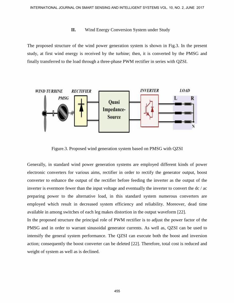
The proposed structure of the wind power generation system is shown in Fig.3. In the present
study, at first wind energy is received by the turbine; then, it is converted by the PMSG and
finally transferred to the load through a three-phase PWM rectifier in series with QZSI.
Figure.3. Proposed wind generation system based on PMSG with QZSI
Generally, in standard wind power generation systems are employed different kinds of power
electronic converters for various aims, rectifier in order to rectify the generator output, boost
converter to enhance the output of the rectifier before feeding the inverter as the output of the
inverter is evermore fewer than the input voltage and eventually the inverter to convert the dc / ac
preparing power to the alternative load, in this standard system numerous converters are
employed which result in decreased system efficiency and reliability. Moreover, dead time
available in among switches of each leg makes distortion in the output waveform [22].
In the proposed structure the principal role of PWM rectifier is to adjust the power factor of the
PMSG and in order to warrant sinusoidal generator currents. As well as, QZSI can be used to
intensify the general system performance. The QZSI can execute both the boost and inversion
action; consequently the boost converter can be deleted [22]. Therefore, total cost is reduced and
weight of system as well as is declined.
INTERNATIONAL JOURNAL ON SMART SENSING AND INTELLIGENT SYSTEMS VOL. 10, NO. 2, JUNE 2017
455

It seems that usage of PMSG in the structure is the most prosperous configuration because of
declined conservation cost, high accuracy, and enhanced reliability of electrical grid due to the
lack of gearbox.
III. Physics Model of Wind Turbine
For steady-state calculations mechanical power from a wind turbine, the Cp (λ, β) curve can be
used. Mechanical power can be determined with the following equation,
31( , )
2mec r pP A C v (1)
r rr
(2)
Where, the power coefficient (Cp), the angle of blade (β), the tip speed ratio (λ), the wind speed
(v), rotor speed (Ωr), the radius of the rotor (rr), the air density (ρ), and the area swept by rotor
(Ar).
The power coefficient is defined as follows,
2 0.1710.022 5.6 e
2pC (3)
The air density is 1.225 kg/m3 at atmospheric pressure. Since the site location is effective in air
density, therefore, the following equation is considered,
0.297 h30481.225e
(4)
Where, 'h' in unit meter is site height.
IV. Mathematic Model of Permanent-Magnet Synchronous Generator (PMSG)
In this section, dynamic equations of PMSG in d&q synchronous reference frame are reviewed;
exactly,
s ds d s s d d q s q
dV R I
dt
(5)
s q
s q s s q d q s d
dV R I
dt
(6)
Hamed Javaheri Fard, DESIGN AND IMPLEMENTATION OF PREDICTIVE CONTROLLERS ON THE RECTIFIER AND QUASI IMPEDANCE-SOURCE INVERTER IN A WIND ENERGY CONVERSION SYSTEM BASED ON PERMANENT MAGNET SYNCHRONOUS GENERATOR
456

s d s d s d r dL I (7)
s q s q s qL I (8)
Where, Vs-d, Vs-q, Is-d, and Is-q are the stator voltage and the stator current in the d&q components,
respectively. Also, Rs is the stator resistance; Ls-d and Ls-q are the d&q stator inductances. φs-d and
φs-q are the d&q stator flux linkage. φr-d is the permanent magnet flux linkage. ωd-q is the angular
electrical rotor speed.
As well as, relationship between applied torques equations with the PMSG rotor is,
el
3Np
2s d s q r d s qT I I (9)
el LO D
dT T T J
dt
(10)
Where, Tel, TLO, TD are the electromagnetic torque, the load torque and the damping torque,
respectively. 'J' is the inertia. 'ω' is the rotational speed. 'Np' is number of pole pairs.
V. Model Based Predictive Control Strategy Principle
Model based predictive control (MBPC) being common in the recent decades has been played a
significant role in the novel control engineering. This type of control contains the extensive range
of applications including big industrial and even food industry as well. The phrase, MBPC, does
not represent a particular control procedure; it refers to the wide range of the control methods in
which obtaining control signal is possible by using minimum of a Cost Function through an
explicit processing model [23]. These design methods provides the linear controllers which have
the resembling structure and identical degree of freedom [23].
The basic idea emerged in the predictive control family is based on the following cases [23]:
- Applying a model to predict the output of the plant in the future times.
- Calculating a series control with the aid of minimizing of a Cost Function.
- Applying the receding horizon principle which contains the usage of the first control
component in the calculated series control at any moment.
Variant algorithms of predictive control strategy between themselves are merely diverse in the
model used to show the plant, jamming, and the Cost Function which has to be minimized. This
control strategy is frequently applied in the industry. Among the applications of this type of
INTERNATIONAL JOURNAL ON SMART SENSING AND INTELLIGENT SYSTEMS VOL. 10, NO. 2, JUNE 2017
457

control are the usages of them in robot arm, steam generators, and so on. These applications
indicate the capacity of predictive control strategy to achieve the most effective control systems.
Some of the MBPC benefits are as follows:
- This control strategy can be used to control illimitable fields of processes whether with
simple dynamics or with complicated dynamics such as the systems with big time delays,
the phase non-minimum systems, or the unstable systems [23].
- The multi-variable systems will be simply controlled by MBPC [23].
- This strategy is appropriate for the dead-time systems [23].
The mentioned strategy also has drawbacks. Obtaining the control signal is more complex than
that of the classic Proportional-Integral-Derivative (PID) controllers [23]. If the dynamic of the
process does not alter, the controller factors can be prearranged, but all calculations should be
repeated for each time sample at the mode of adaptive control. As well as, the mathematical
calculations will be more at the presence of constraints. Also, a proper model is an essential
necessity. Anyway, the benefits have excellence over disadvantages making it extremely
beneficial in the industry.
A. MBPC for Power Converters and Drives
The predictive control contains a widespread category of controllers which has recently been
used to control the power converters. With the help of predictive control strategy the cascade
structure will be removed, which is generally used for the application of linear control; and this
will be a great advantage. Also, one benefit of this strategy is that concepts are much simple and
achieved transient responses are extremely fast.
Fig.4 shows prevalent predictive control strategy scheme for power converters and drives. It does
not matter what kind of topology is the power converter or how many phases it possesses,
however this strategy can be used. The load shown in Fig.4 could be each model of passive and
active load, an electrical machine or the electrical grid. In this figure, X*(k) presented the
reference values for predictive control strategy. X (k) represents measured variables that are used
in the model to calculate predictions of the controlled variables, namely X (k+1), for each one of
'n' possible switching states that can be voltages, switching states, or currents. The existing error
between the predicted and reference values is achieved in order to minimize a cost function and
Hamed Javaheri Fard, DESIGN AND IMPLEMENTATION OF PREDICTIVE CONTROLLERS ON THE RECTIFIER AND QUASI IMPEDANCE-SOURCE INVERTER IN A WIND ENERGY CONVERSION SYSTEM BASED ON PERMANENT MAGNET SYNCHRONOUS GENERATOR
458

the switching state; then, switching state that minimizes the cost function is selected. The optimal
actuation 'S' is chosen; afterwards, it is applied to the converter.
Figure.4. Predictive control strategy block diagram for power converters
VI. Proposed MBPC on the Rectifier Associated with the PMSG
One of the most common power converters, used in energy conversion systems especially wind,
is rectifiers. In this section, proposed predictive control strategy is implemented on the converter
(rectifier) of the generator side.
To begin, by putting (7) and (8) in (5) and (6), the following equations can be taken. In fact, with
the help of stator voltage and stator flux equations, stator current derivatives are extracted in two
components d and q.
Thus,
1s ds d s s d d q s q s q
s d
dIV R I L I
Ldt
(11)
1s q
s q s s q d q r d s q s ds d
dIV R I L I
Ldt
(12)
Here, it should be expressed that the stator voltages and currents are in vector state.
INTERNATIONAL JOURNAL ON SMART SENSING AND INTELLIGENT SYSTEMS VOL. 10, NO. 2, JUNE 2017
459

The discrete-time model will be employed in order to predict the future value of stator current
from voltages and measured currents at the k Th sampling interval. Through this action,
implementation of strategy is easier in the simulation software and as well as simulation on
digital platforms such as DSP. To achieve a discrete-time model it is requisite to employ some
discretization techniques. In here, Stator currents will be discrete in two components with the
help of forward Euler discretization method. Thus, the predicted stator current components in
(k+1) Th sampling interval are found according to the equations (13) and (14),
1
1 S s Ss d s d s d s d
s d s d
T R TI k V k E k I k
L L
(13)
1
1 S s Ss q s q s q s q
s q s q
T R TI k V k E k I k
L L
(14)
'TS' is the sampling time. In the above equations induced electromotive force (EMF) in two
components can be found through the following equations,
s d s q d q s qE k L k I k (15)
s q d q s d s d r dE k k L I k k (16)
Figure.5. Three-phase rectifier topology
Hamed Javaheri Fard, DESIGN AND IMPLEMENTATION OF PREDICTIVE CONTROLLERS ON THE RECTIFIER AND QUASI IMPEDANCE-SOURCE INVERTER IN A WIND ENERGY CONVERSION SYSTEM BASED ON PERMANENT MAGNET SYNCHRONOUS GENERATOR
460

In fact, the proposed MBPC strategy is based on this principle that merely a finite number of
possible switching states can be produced by the power converter; also, the operation of the
variables is predicted by means certain models of the system in every switching state.
Here, the two switches in each converter of the generator side phase act in a complementary
mode due to avoid short circuiting the input voltage (Fig.5). Thus, the number of power switches
is six. These switches are considered in the form of three switching signals namely SA, SB, SC, as
follows,
1 4
A
1 4
2 5
B
2 5
3 6
C
3 6
1S
0
1S
0
1S
0
s on s off
s off s on
s on s off
s off s on
s on s off
s off s on
So, there will be eight switching states according to the following table,
Table 1: Switching states and voltage vectors
SA SB SC Stator Voltage
Vectors
0 0 0 V0=0
1 0 0 V1=(2/3)Vi
1 1 0 V2=(1/3 +j√3/3) Vi
0 1 0 V3=(-1/3 +j√3/3) Vi
0 1 1 V4=-(2/3)Vi
0 0 1 V5=(-1/3 -j√3/3) Vi
1 0 1 V6=(1/3 -j√3/3) Vi
1 1 1 V7=0
In table 1, 'Vi' represents the input voltage; the same voltage at the input quasi impedance-
network. It is clear from the table that voltage vectors are composed of two components of real
and imaginary; apart from zero and seven vectors that represent a finite set of voltage vectors. If
INTERNATIONAL JOURNAL ON SMART SENSING AND INTELLIGENT SYSTEMS VOL. 10, NO. 2, JUNE 2017
461

the real and imaginary parts of the voltage vectors respectively, from zero to seven, Vs-αN and Vs-
βN designated so that N=0…..7 (e.g. V1= (2/3) Vi → V1= Vs-α
1 + 0Vs-β
1), the stator voltage vectors
in d&q are calculated as follows,
N N N
N N N
( ) COS ( ) ( ) SIN ( ) ( )
( ) SIN ( ) ( ) COS ( ) ( )
s d d q s d q s
s q d q s d q s
V k k V k k V k
V k k V k k V k
(17)
The relation (17), stator voltage components at the k Th sampling interval, has been attained with
the help of a rotating mechanism and using an angle namely 'θd-q' in α&β frame.
Now, with respect to the voltages in the mentioned evolution, i.e. (17), the stator current vectors
in equations (13) and (14) be rewritten as follows,
N 0 7 N N 11 S s S
s d s d s d s d
s d s d
T R TI k V k E k I k
L L
(18)
N 0 7 N N 11 S s S
s q s q s q s q
s q s q
T R TI k V k E k I k
L L
(19)
In equations (18) and (19), the predicted stator currents have been obtained in d&q reference at
the (k+1) Th sampling interval when stator voltage components are applied during k Th sampling
interval.
In the following, with the help of reference stator current vectors at the k Th sampling interval,
the applied error in the cost function can be found as follows,
N NΕr 1 1s d s d s dI k I k I k
(20)
N NΕr 1 1s q s q s qI k I k I k
(21)
In relations (20) and (21), symbol of 'Er' represents the error between the reference values and the
predicted values. Also, symbol of '*' represents the reference value.
The goal of the control proposed scheme is in order to minimize the occurred error between the
measured currents in plant and the reference currents in plant. This necessity can be illustrated in
the framework of a cost function. Therefore,
N N
1CF Εr 1 Εr 1s d s qI k I k (22)
Finally, the switching state which minimizes the cost function is applied to rectifier.
The block diagram of the proposed control scheme can be seen in Fig.6.
Hamed Javaheri Fard, DESIGN AND IMPLEMENTATION OF PREDICTIVE CONTROLLERS ON THE RECTIFIER AND QUASI IMPEDANCE-SOURCE INVERTER IN A WIND ENERGY CONVERSION SYSTEM BASED ON PERMANENT MAGNET SYNCHRONOUS GENERATOR
462

Figure.6. Proposed MBPC for rectifier associated with the PMSG
VII. Proposed MBPC on the QZSI in the Wind Energy Conversion System
A. The Introduction and Function of QZSI
The three-phase Impedance-Source Inverters (ZSI) [24, 25] topology was presented for the first
time, with structure of a buck boost inverter in a single stage conversion. It provides a greater
voltage boost gain and removes overlapping problem among the inverter switches and a
distortion in the inverter output current because of the presence of the dead time. Nevertheless, it
has drawbacks of a discontinuous input current and a great voltage stress in between both its
capacitors.
An novel and perfected topology of ZSI known as Quasi Impedance-Source Inverter (QZSI) [26,
27] provides a superior option along with the continuous input current and a fewer voltage stress
among one of its capacitor while sustaining a same ability as the primary ZSI with the same
number of elements.
INTERNATIONAL JOURNAL ON SMART SENSING AND INTELLIGENT SYSTEMS VOL. 10, NO. 2, JUNE 2017
463

The structure of a ZSI and a QZSI can be seen in the Fig.7 and Fig.8, respectively.
Figure.7. Three-phase Impedance-Source Inverter (ZSI)
Figure.8. Three-phase Quasi Impedance-Source Inverter (QZSI)
As can be seen in Fig.8, the quasi impedance network has been consist from an asymmetrical 'LC'
network including L1, L2, C1, C2 along with an Diode. The QZSI has three modes of work; these
modes are Active state, Null state and Shoot-through state. In the case of active state operation,
Hamed Javaheri Fard, DESIGN AND IMPLEMENTATION OF PREDICTIVE CONTROLLERS ON THE RECTIFIER AND QUASI IMPEDANCE-SOURCE INVERTER IN A WIND ENERGY CONVERSION SYSTEM BASED ON PERMANENT MAGNET SYNCHRONOUS GENERATOR
464

inverter will be control similar to typical methods. In the case of null state operation, the upper
inverter switches or all of the three under switches of inverter will be switched on. If the two
switches are turned on at the same time at a leg, then, the shoot-through state operation will be
created; the consequence of this state is that one or three legs of the converter will be short
circuit. Consider the Fig.9.
For more information about the QZSI operation modes refer to [27].
Figure.9. Overall structure of operational modes for QZSI
INTERNATIONAL JOURNAL ON SMART SENSING AND INTELLIGENT SYSTEMS VOL. 10, NO. 2, JUNE 2017
465

According to the Fig.8, the basic equations for the QZSI are as follows [27],
C1
1
1 2i
dV V
d
(23)
Where, parameter d is duty ratio and VC1 is capacitor voltage C1.
C2
1 2i
dV V
d
(24)
1 2
DC i
dV V
d
(25)
Where, VC2 is capacitor voltage C2 and VDC is DC link voltage.
SHTd
T (26)
Where, TSH and T are the shoot-through period and the switching period, respectively.
1
1 2B
d
(27)
Where, B is the boost coefficient.
B. Proposed MBPC on the QZSI
The use of the QZSI will cause the entire energy conversion system performance be better
compared to the conventional inverters and ZSI. As already was mentioned, the QZSI based
system can perform both the boosting and inversion action; accordingly the boost converter can
be eliminated [22]. Consequently, the system cost greatly reduces, and weight of system as well
decreased. In this section the proposed predictive control strategy is implemented on the QZSI.
The overall structure connecting the QZSI to the wind energy conversion system based PMSG is
given in the Fig.10.
From the fifteen switching states of inverter, the six states is related to the Active state and the
two states is related to the Null state and the remaining, seven, is related to the Shoot-through
state; in accordance with the Table 2, [28]. These states are able that be transformed from three-
phase to two-phase. It should be expressed that the Null states and the Shoot-through states can
be placed in a group since they produce the identical voltage vectors. Therefore, according to this
principle, the required time in order to calculate the voltage vectors as well as their number will
be reduced.
Hamed Javaheri Fard, DESIGN AND IMPLEMENTATION OF PREDICTIVE CONTROLLERS ON THE RECTIFIER AND QUASI IMPEDANCE-SOURCE INVERTER IN A WIND ENERGY CONVERSION SYSTEM BASED ON PERMANENT MAGNET SYNCHRONOUS GENERATOR
466

Figure.10. Block diagram-based wind energy conversion system with QZSI topology
Table 2: Switching states and voltage vectors for QZSI
S1 S4 S3 S6 S5 S2 Output Voltage Vectors
1 0 1 0 1 0 V0=0
0 1 0 1 0 1 Null state
1 0 0 1 0 1 V1=(2/3)VC1
1 0 1 0 0 1 V2=(1/3 +j√3/3) VC1
0 1 1 0 0 1 V3=(-1/3 +j√3/3) VC1
0 1 1 0 1 0 V4=-(2/3) VC1
0 1 0 1 1 0 V5=(-1/3 -j√3/3) VC1
1 0 0 1 1 0 V6=(1/3 -j√3/3) VC1
1 1 0 0 0 0
0 0 1 1 0 0 V7=0
0 0 0 0 1 1
1 1 1 1 0 0 Shoot-through state
0 0 1 1 1 1
1 1 0 0 1 1
1 1 1 1 1 1
Active
state
INTERNATIONAL JOURNAL ON SMART SENSING AND INTELLIGENT SYSTEMS VOL. 10, NO. 2, JUNE 2017
467

With regard to the unitary vector namely a = e (j2π) / 3
= (-1 / 2) + j (√3 / 2) that indicates the 120
degrees' phase displacement among the phases, the vector of output voltage produced by the
inverter can be described as follows,
22
3an bn cnV v av a v (28)
According to the Fig.10, van, vbn, and vcn are the phase to neutral (n) voltages of the inverter.
In accordance with Fig.10, if van, vbn, and vcn for each phase be defined as follows,
NL Ra
an a n
div i v
dt (29)
NL Rb
bn b n
div i v
dt (30)
NL Rc
cn c n
div i v
dt (31)
Where, R and L are the load resistance and the load inductance, respectively. Moreover, ia, ib, and
ic are the current each phase. Note that these currents along with 'vnN' are not shown on the
Fig.10.
Then, through substituting equations (29-31) into (28), this equation can be rewritten as follows,
2 2
2
N N N
2 2L R
3 3
2
3
a b c a b c
n n n
dV i ai a i i ai a i
dt
v av a v
(32)
With regard to the vector equation (28) and the following definition for the load current,
2
LOAD
2
3a b cI i ai a i (33)
And assuming,
2 2
N N N N
2 21 0
3 3n n n nv av a v v a a (34)
The voltage vector generated by the inverter or the same the output voltage achieves as follows,
LOADLOADL R
dIV I
dt (35)
In the following, we refer to this important issue that for each of the operation modes, the main
variables for prediction action are: the capacitor voltage for C1 (VC1) that according to the Table
Hamed Javaheri Fard, DESIGN AND IMPLEMENTATION OF PREDICTIVE CONTROLLERS ON THE RECTIFIER AND QUASI IMPEDANCE-SOURCE INVERTER IN A WIND ENERGY CONVERSION SYSTEM BASED ON PERMANENT MAGNET SYNCHRONOUS GENERATOR
468

2, output voltage vectors are dependent on it. The inductor current for L1 (IL1) which it is input
current into the quasi impedance network; and finally the load current (ILOAD).
B.i Active State Operation
The following equations are obtained for Active State according to the Fig.9 and as well Fig.10,
C1
L1 INV
1
INV LOAD
1
C
in Active state
dVI I
dt
I I
(36)
L1L1 C1
1
1r
Li
dIV I V
dt
(37)
Where, ' r ' and IINV are the internal resistance of inductance 'L1' and the input current into the
three-phase inverter, respectively.
B.ii Null State Operation
Again from the Fig.9, the equations (38) and (39) will be obtained,
C1L1
1
1
C
dVI
dt
(38)
L1L1 C1
1
1r
Li
dIV I V
dt
(39)
B.iii Shoot-Through State Operation
Again from the Fig.9, the following equation will be obtained,
C1L1
1
1
C
dVI
dt
(40)
L1C1
1
1
L
dIV
dt
(41)
B.iv Discrete-Time Model for Prediction
Here, the discretization of mentioned variables will be done by a forward Euler approximation.
INTERNATIONAL JOURNAL ON SMART SENSING AND INTELLIGENT SYSTEMS VOL. 10, NO. 2, JUNE 2017
469

This discretization is useful in order to predict the future value of capacitor voltage (VC1), the
inductor current (IL1), and load current (ILOAD).
Thus, the derivation of mentioned variables will be as follows,
C1 C1 C1( ) ( )S
S
dV V t V t T
dt T
(42)
L1 L1L1( ) ( )S
S
I t I t TdI
dt T
(43)
LOAD LOAD LOAD( ) ( )S
S
dI I t I t T
dt T
(44)
Using the equation (35), the derivative of the load current is extracted as follows,
LOADLOAD
1R
L
dIV I
dt
(45)
Then, the load current at time t will be achieved by combining the two equations (44) and (45) as
follows,
LOAD LOAD LOAD( ) ( ) R ( ) ( )L
SS
TI t V t I t I t T (46)
Finally, by the shift of time at the load current from t to (t+TS), behavior of the load current in the
future will be found in equation (47),
LOAD LOAD
1( ) ( ) L ( )
L RS S S
S
I t T T V t T I tT
(47)
In the equation (47), V (t+TS) represents the output voltage at (t+TS); this voltage is produced by
appropriate control of the switches.
In the following, with an emphasis on the Fig.9, the predictive equations of future values will be
displayed for inductor current (IL1) in each of the three modes.
Active State Operation
With the help of equations (37) and (43), the inductor current (IL1) at time t will be achieved as
follows,
L1 C1 1 L1
1
1( ) ( ) L ( )
L rS i S
S
I t T V V t I t TT
(48)
And also, future behavior of equation (48) can be obtained with same as the shift of time as
follows,
Hamed Javaheri Fard, DESIGN AND IMPLEMENTATION OF PREDICTIVE CONTROLLERS ON THE RECTIFIER AND QUASI IMPEDANCE-SOURCE INVERTER IN A WIND ENERGY CONVERSION SYSTEM BASED ON PERMANENT MAGNET SYNCHRONOUS GENERATOR
470

C1
L1 C1 1 L1
1( )
1( ) ( ) L ( )
L rS S i S
SV t
I t T T V V t T I tT
(49)
Since the changes in the capacitor voltage is very low, so it can be concluded that VC1 (t+TS) ≅
VC1 (t).
Null State Operation
In this mode, the predictive equation for inductor current (IL1) is similar to Active State
Operation. Pay attention to the equation (50),
L1 C1 1 L1
1
1( ) ( ) L ( )
L rS S i S
S
I t T T V V t T I tT
(50)
Here, also, according to the above mentioned reason it can be assumed that VC1 (t+TS) ≅ VC1 (t).
Shoot-Through Operation
In this state, since the input voltage at the input quasi impedance-network (Vi) does not effect on
the circuit, considering the Fig.9 and equations (41) and (43), the predictive equation for inductor
current (IL1) will be according to the following equation,
L1 C1 1 L1
1
1( ) ( ) L ( )
L rS S
S
I t T V t I t TT
(51)
The equation for predicting the inductor current is gained from the following formula,
C1
L1 C1 1 L1
1( )
1( ) ( ) L ( )
L rS S S
SV t
I t T T V t T I tT
(52)
It is observed that in mentioned modes, another relevant variable to predict future behavior
inverter was calculated.
Now, without any waste of time, capacitor voltage (VC1) at the QZSI shall be calculated in three
modes of operation. Therefore,
Active State Operation
With the help of equations (36) and (42), the capacitor voltage (VC1) at time t will be achieved as
follows,
C1 L1 INV C1
1
INV LOAD
( ) ( ) ( ) ( )C
in Active state
SS
TV t I t I t V t T
I I
(53)
INTERNATIONAL JOURNAL ON SMART SENSING AND INTELLIGENT SYSTEMS VOL. 10, NO. 2, JUNE 2017
471

And also, future behavior of equation (53) can be obtained with same as the shift of time as
follows,
Eq
C
u
1 L1 LOAD C1
1 ation(33)
( ) ( ) ( ) ( )C
SS S S
TV t T I t T I t T V t
(54)
Null State Operation
By using equations (38) and (42), the capacitor voltage (VC1) at time t will be achieved as
follows,
C1 L1 C1
1
( ) ( ) ( )C
SS
TV t I t V t T (55)
And its predictive equation will be as follows,
C1 L1 C1
1
( ) ( ) ( )C
SS S
TV t T I t T V t (56)
Shoot-Through Operation
By applying the equations (40) and (42), the capacitor voltage (VC1) at time t will be achieved as
follows,
C1 L1 C1
1
( ) ( ) ( )C
SS
TV t I t V t T
(57)
And its predictive equation will be as follows,
C1 L1 C1
1
( ) ( ) ( )C
SS S
TV t T I t T V t
(58)
In this way, all three required variables in order to study of behavior of the QZSI predictions
were calculated for each of the three modes of operation.
B.v Predictive Control Scheme
In fact the predictive control strategy, proposed in this paper for the QZSI, is based on this
principle that the future values of the load current (ILOAD), the inductor current (IL1), and capacitor
voltage (VC1) are predicted for the essential switching states produced by the inverter, by means
of (47), (49), (52), (54), (56), and (58). In achieving this object, it is required to measure the
present time of these variables. After acquiring the predictions, a cost function (CF) is evaluated
for each switching state. Eventually, the switching state which minimizes the CF is chosen and
applied during the next sampling time.
Hamed Javaheri Fard, DESIGN AND IMPLEMENTATION OF PREDICTIVE CONTROLLERS ON THE RECTIFIER AND QUASI IMPEDANCE-SOURCE INVERTER IN A WIND ENERGY CONVERSION SYSTEM BASED ON PERMANENT MAGNET SYNCHRONOUS GENERATOR
472

In this part, the cost function for the QZSI must be defined. Therefore, the requirements related to
the variables control will be reviewed once again; as follows,
- The load current reference tracking
- The inductor current reference tracking
- The capacitor voltage reference tracking
As a result, this requirement should be exist in the cost function.
By defining the following errors,
Re Re Re
P
LOAD LOAD LOADΕr S S SI t T I t T I t T (59)
Im Im Im
P
LOAD LOAD LOADΕr S S SI t T I t T I t T (60)
P
C1 C1 C1Εr S S SV t T V t T V t T (61)
P
L1 L1 L1Εr S S SI t T I t T I t T (62)
Then, the cost function will be determined as follows so that this CF considers the absolute error
between the reference values and the predicted values,
Re Im
C1 L1
LOAD LOAD
C1 L1
CF Εr Εr
wf Εr wf Εr
S S
V S I S
I t T I t T
V t T I t T
(63)
In the above relations, symbol of 'Er' is the same error and symbol of '*' represents reference
value of variables and as well, symbol of 'P' represents predicted value of variables. Also, it can
be seen that the load current has both real (Re) and imaginary (Im) components. These two
components are generated by the Clark and three-phase currents i.e. ia, ib, and ic.
In relation (63) have been used two criteria to the relevance control objectives. These two criteria
are called weighting factors namely 'C1
wfV and 'L1
wfI . Although this parameter is a scalar it
should be pointed out that the adjustment of 'wf' is still an open and interesting topic for study.
Precise adjustment of the weighting factor is important because by using that can have a control
system with favorable performance. For systems with a finite number of control actions, finite
input sets, or state alphabet, one method to adjust the parameter is to simply evaluate the
performance of specific system variables by simulations to determine the best value [29]. For cost
functions with equally important terms, the cost function must be normalized, and then the
weighting factor must be set to wf = 1. With this value the system will be controlled and, for fine
INTERNATIONAL JOURNAL ON SMART SENSING AND INTELLIGENT SYSTEMS VOL. 10, NO. 2, JUNE 2017
473

tuning, branch and bound can be used or slight variations of 'wf' around 1 can be tested [29]. In
this paper C1
wf 0.85V and L1
wf 3.95I is considered, of course, by trial and error.
The proposed predictive control scheme for the QZSI in the wind energy conversion system
based on PMSG is shown in Fig.11.
Figure.11. Scheme of the proposed predictive control strategy for QZSI
VIII. Simulation Results
To verify the performance of the proposed control strategy for both Quasi Impedance-Source
Inverter (QZSI) and the rectifier associated with the PMSG in the wind turbine system, a series of
simulation tests developed under MATLAB/Simulink software were carried out.
The fundamental simulation parameters have been given in Table 3. The accurate calculation of
these parameters and their associated relationships is clearly shown in [30]. The sampling time in
this control is TS = 25μs. The intended switching frequency of proposed predictive control
strategy is 10 kHz. It should be noted that there is no requirement for a modulator, which is the
principal part of the traditional controller.
Hamed Javaheri Fard, DESIGN AND IMPLEMENTATION OF PREDICTIVE CONTROLLERS ON THE RECTIFIER AND QUASI IMPEDANCE-SOURCE INVERTER IN A WIND ENERGY CONVERSION SYSTEM BASED ON PERMANENT MAGNET SYNCHRONOUS GENERATOR
474

Table 3: Simulation parameters
R : load resistance 12 Ω
L : load inductance 12 mH
TS : sampling time 25μs
QZSI inductance 350μH
QZSI capacitance 330μF
ω*: speed reference of the PMSG
225 rad/s
Np : number of pole pairs for PMSG 4
s dI
: stator current reference at d component 0
Vi : input voltage 55 v
At first, the response speed of the generator is shown in Fig.12. As seen in the figure, there is a
step change in the speed at instant t = 0.24 sec. It is obvious that PMSG speed tracks their
reference very well.
Figure.12. Tracking speed and its reference of PMSG
0 0.1 0.2 0.3 0.4 0.5 0.6 0.70
30
60
90
120
150
180
210
Time [sec]
w &
w*
[ra
d/s
ec]
Speed PMSG
INTERNATIONAL JOURNAL ON SMART SENSING AND INTELLIGENT SYSTEMS VOL. 10, NO. 2, JUNE 2017
475

Assuming the wind speed is considered constant at all times, it is seen that speed of the generator
is completely smooth. It is worth noting that wind speed in this paper is considered 13 m/sec. It
can be said that due to the desirable design and implementation of the proposed predictive
strategy on the rectifier associated with the PMSG, the accuracy of tracking speed is really high.
In the following three-phase shown load current is shown in Fig.13. It is clear that this current is
sine exactly.
Figure.13. Tracking three-phase load current and its reference
As can be observed from the figure, the dynamics response of the current is quite fast. Three-
phase current have reached to their maximum value without any overshoot. Three-phase current
has a step change at instant t = 0.24 sec that this change is equivalent to the change in speed
generator. In Fig.13, it is clear that the three-phase load current have very small ripple. If the
sampling time is reduced, for example from TS = 25μs to the TS = 15μs, the existing ripple can be
decreased. However, it is seen that the dynamic response is precisely tracking the reference
values; and this is because the proposed strategy on the QZSI side is designed efficiently.
0 0.1 0.2 0.3 0.4 0.5 0.6 0.7
-2
0
2
Time [sec]
I L
OA
D [A
]
Load Current
Hamed Javaheri Fard, DESIGN AND IMPLEMENTATION OF PREDICTIVE CONTROLLERS ON THE RECTIFIER AND QUASI IMPEDANCE-SOURCE INVERTER IN A WIND ENERGY CONVERSION SYSTEM BASED ON PERMANENT MAGNET SYNCHRONOUS GENERATOR
476

If a frequency spectrum analysis or FFT was performed on one of the phases of the load current,
it is observed that the Total Harmonic Distortion (THD) is 1.77%. Total Harmonic Distortion is a
qualitative parameter and represents to what extent a signal or waveform is close to the sinusoidal
waveform. THD value is expressed based on the percentage. Whatever THD be lower the
sinusoidal waveform quality will be better. The current spectrum of the proposed MBPC strategy
is specified in Fig.14 by discrete spectral lines. In spite of the fact that the switching frequency
for the proposed predictive control is not constant, it does not have great variation.
Figure.14. Load current spectrum analysis
In the following, the input current into the impedance network namely the inductor current (IL1) is
depicted in Fig.15. Inductor current corresponding to the three-phase load current has a step
change at instant t = 0.24 sec. As can be seen from figure, this current has ripple; of course, the
value of this ripple is very low. It is obvious that predicting the future values for the inductor
current in the input impedance network carried out very well and these values accurately track
their reference values.
It is known that tracking is highly robust because of the detailed design of the proposed MBPC
strategy. Because of this strategy is robust should therefore state that this current tracking will be
0 0.01 0.02 0.03 0.04 0.05 0.06 0.07 0.08 0.09 0.1
-100
0
100
Selected signal: 6 cycles. FFT window (in red): 2 cycles
Time (s)
0 2000 4000 6000 8000 100000
0.5
1
Frequency (Hz)
Fundamental (50Hz) = 149.2 , THD= 1.77%
Mag (
% o
f F
undam
enta
l)
0 0.01 0.02 0.03 0.04 0.05 0.06 0.07 0.08 0.09 0.1
-100
0
100
Selected signal: 6 cycles. FFT window (in red): 2 cycles
Time (s)
0 2000 4000 6000 8000 100000
0.5
1
Frequency (Hz)
Fundamental (50Hz) = 149.2 , THD= 1.77%
Ma
g (
% o
f F
un
da
me
nta
l)
INTERNATIONAL JOURNAL ON SMART SENSING AND INTELLIGENT SYSTEMS VOL. 10, NO. 2, JUNE 2017
477

there with its reference value despite the unbalanced grid; which of course we did not show this
case in the paper.
The stator current of PMSG has been shown in the d&q components (Is-q, and Is-d) in Fig.16 and
Fig.17, respectively. The stator current in q component has a step change at instant t = 0.24 sec,
which PI controller available in Fig.6 responds to it. It can be seen from Fig.16, which
the future values are predicted in the q component very well; and tracking the reference values
has been done exactly.
It can be seen in Fig.17, which the stator current in d component is zero even during the
transients due to acquire the maximum torque. Therefore, by using the proposed predictive
control strategy has realized both terms available in the first cost function 'CF1' namely stator
current in the d&q components.
Figure.15. Tracking inductor current or input current into the impedance network along with
its reference
0 0.1 0.2 0.3 0.4 0.5 0.6 0.70
1
2
3
4
5
6
Time [sec]
I L
1 [
A]
Inductor Current
Hamed Javaheri Fard, DESIGN AND IMPLEMENTATION OF PREDICTIVE CONTROLLERS ON THE RECTIFIER AND QUASI IMPEDANCE-SOURCE INVERTER IN A WIND ENERGY CONVERSION SYSTEM BASED ON PERMANENT MAGNET SYNCHRONOUS GENERATOR
478

Figure.16. Tracking stator current of PMSG in q component and its reference
Figure.17. Tracking stator current of PMSG in d component and its reference
0 0.1 0.2 0.3 0.4 0.5 0.6 0.7
-6
-3
0
3
6
Time [sec]
I s-q
[A
]
Stator Current PMSM
0 0.1 0.2 0.3 0.4 0.5 0.6 0.7
-6
-3
0
3
6
Time [sec]
I s-d
[A
]
Stator Current PMSM
INTERNATIONAL JOURNAL ON SMART SENSING AND INTELLIGENT SYSTEMS VOL. 10, NO. 2, JUNE 2017
479

In the next phase of simulation results if the step change, applied to the previous results at instant
t = 0.24 sec, be remove and as well as load inductance and load resistance changed from R = 6 Ω
to L = 6 mH, then it should be noted that the three-phase load current and its reference are still
sinusoidal but the existing ripple has been increased slightly. Of course, the ripple of current can
be reduced by reducing sampling time which will lead to increased switching frequency.
Figure.18. Tracking three-phase load current and its reference without the step change
It is known that like the previous case, the predicted values closely track the reference values.
Therefore, we can conclude that the proposed MBPC strategy is certainly robust that even with
the change of load parameters also does not lose its quality. The modified three-phase load
current waveform is shown in Fig.18.
In Fig.19, the load voltage has been given in the phase a relative to the neutral point. It is worth
mentioning that in obtaining this voltage is avoided from any kind of series-parallel or capacitive-
inductive filter. It is clear that the switching action is desirable in the voltage because of the
appropriate selection of sampling time.
0 0.1 0.2 0.3 0.4 0.5 0.6 0.7
-2
-1
0
1
2
Time [sec]
I L
OA
D [
A]
Load Current
Hamed Javaheri Fard, DESIGN AND IMPLEMENTATION OF PREDICTIVE CONTROLLERS ON THE RECTIFIER AND QUASI IMPEDANCE-SOURCE INVERTER IN A WIND ENERGY CONVERSION SYSTEM BASED ON PERMANENT MAGNET SYNCHRONOUS GENERATOR
480

Figure.19. Load voltage van without filter
Without any additional work, the response of the three-phase load voltage is depicted in Fig.22.
But unlike the load voltage obtained in the previous case, here, a capacitive-inductive filter is
used in order to obtain the load voltage in the output part. The value of parameters, used for filter,
is LF = 4 mH and CF = 25μF.
Figure.20. Filter circuit in output in the MATLAB/Simulink
0 0.1 0.2 0.3 0.4 0.5 0.6 0.7
-300
-200
-100
0
100
200
300
Load Voltage
Time [sec]
V L
OA
D [V
]
INTERNATIONAL JOURNAL ON SMART SENSING AND INTELLIGENT SYSTEMS VOL. 10, NO. 2, JUNE 2017
481

How to connect and implementation of the output filter in MATLAB environment is depicted in
Fig.20 and Fig.21.
Figure.21. Value of parameters, used for filter, in the MATLAB/Simulink
Figure.22. Load voltage with filter LF = 4 mH and CF = 25μF
0 0.1 0.2 0.3 0.4 0.5 0.6 0.7
-300
-150
0
150
300
Time [sec]
V L
OA
D [V
]
Load Voltage
0.4 0.42 0.44 0.46 0.48 0.5
-300
-150
0
150
300
Time [sec]
Load Voltage
Hamed Javaheri Fard, DESIGN AND IMPLEMENTATION OF PREDICTIVE CONTROLLERS ON THE RECTIFIER AND QUASI IMPEDANCE-SOURCE INVERTER IN A WIND ENERGY CONVERSION SYSTEM BASED ON PERMANENT MAGNET SYNCHRONOUS GENERATOR
482

In Fig.22, if the load voltage has been expanded for example at timeframe 0.4 to 0.44 sec, then it
is observed that this voltage would be quite sinusoidal. The load voltage like the load current has
very small ripple. It is observed that due to the use of powerful predictive strategy, the dynamic
response of voltage is fast. In fact, efficiency and effectiveness of the proposed predictive control
strategy is completely evident.
In the following, the dynamic response of the first capacitor voltage (VC1) in the impedance
network is given in Fig.23. Although, the voltage faces with the little fluctuation around the
reference value, it is obvious that the voltage is tracking the reference value very well. After a
while the capacitor voltage starts from zero, in fact, it is being charged; then, it will be a constant
value.
It is pointed out to this issue that the weighting factor which was previously defined in the cost
function and its value was specified here shows its effectiveness.
Figure.23. Tracking capacitor voltage (VC1) and its reference in the impedance network
0 0.1 0.2 0.3 0.4 0.5 0.6 0.70
25
50
75
100
125
150
175
200
Time [sec]
V C
1 [
V]
Capacitor Voltage
0.2 0.22 0.24 0.26
300
320
Time [sec]
V C
1 [
V]
Capacitor Voltage
INTERNATIONAL JOURNAL ON SMART SENSING AND INTELLIGENT SYSTEMS VOL. 10, NO. 2, JUNE 2017
483

If this factor can't be accurately determined, then the corresponding strategy will lose its weight
of control; consequence of this subject can be the emergence of noise, vibrations, and the lack of
accurate tracking.
Also, in Fig.24 the second capacitor voltage (VC2) in the impedance network is shown.
Figure.24. Capacitor voltage (VC2) in the impedance network
The DC voltage (VDC) or inverter voltage is depicted in Fig.25. In accordance with the inverter
circuit, it is clear that the input voltage to the inverter is the sum of two capacitor voltages, i.e.,
VC1 and VC2. The Inverter voltage is increased slowly and smoothly at wind speed 13 m/sec; then
it reaches a constant value. This point is quite definite in figure which the DC voltage is devoid
of any overshoot that this is benefits of proposed predictive control strategy. It can be expanded
waveform in a particular period for example 0.4 to 0.4001 sec in order to better understand the
DC signal.
Also, the input voltage (Vi) or voltage at the input quasi impedance-network is depicted in Fig.26.
In accordance with the inverter circuit, it is clear that the voltage at the input quasi impedance-
network is the subtraction of two capacitor voltages, i.e., VC1 and VC2. In fact, this voltage is the
same rectifier output voltage.
0 0.1 0.2 0.3 0.4 0.5 0.6 0.70
20
40
60
80
100
120
140
160
Time [sec]
V C
2 [
V]
Capacitor Voltage
0 0.1 0.2 0.3
0
20
40
60
80
100
Time [sec]
V C
2 [
V]
Capacitor Voltage
Hamed Javaheri Fard, DESIGN AND IMPLEMENTATION OF PREDICTIVE CONTROLLERS ON THE RECTIFIER AND QUASI IMPEDANCE-SOURCE INVERTER IN A WIND ENERGY CONVERSION SYSTEM BASED ON PERMANENT MAGNET SYNCHRONOUS GENERATOR
484

Figure.25. DC voltage (VDC) or inverter voltage
Figure.26. Input voltage (Vi) or rectifier output voltage
0 0.1 0.2 0.3 0.4 0.5 0.6 0.70
90
180
270
360
Time [sec]
V D
C [V
]
DC-Link Voltage
0 0.1 0.2 0.3 0.4 0.5 0.6 0.70
10
20
30
40
50
Time [sec]
V i [
V]
Rectifier Output Voltage
0 0.5 1 1.5 2 2.5 3 3.5 4 4.5 5
x 10-3
0
50
100
150
200
250
300
350
400
Time (seconds)
data
Time Series Plot:
INTERNATIONAL JOURNAL ON SMART SENSING AND INTELLIGENT SYSTEMS VOL. 10, NO. 2, JUNE 2017
485

IX. Experimental Results
In this section, the proposed MBPC strategy is verified by experiment using a laboratory
renewable energy system setup, as depicted in Fig.27. The real-time algorithm is implemented by
a prototype platform known as STM32F407VG microcontroller, which controls a three-phase
Quasi Impedance-Source Inverter (QZSI). The inverter will be controlled externally by means an
interface and protection card (IPC). The system parameters are constant exactly the same as the
previous section. Also, the analog to digital conversion and digital to analog conversion have
been specified in figure.
Figure.27. Overview of experimental system setup
Hamed Javaheri Fard, DESIGN AND IMPLEMENTATION OF PREDICTIVE CONTROLLERS ON THE RECTIFIER AND QUASI IMPEDANCE-SOURCE INVERTER IN A WIND ENERGY CONVERSION SYSTEM BASED ON PERMANENT MAGNET SYNCHRONOUS GENERATOR
486

The implementation time for the control algorithm is about 12μs. In Fig.28, three-phase load
current is given. As can be seen the current is sine in practice. The current ripple is very small
with low harmonic distortion. In the load current there is no overshoot. The amplitude of the
reference load current has been set to 2 A in a frequency of 50 Hz. The behavior of the load
voltage in one phase van at steady state operation has been depicted in Fig.29.
Figure.28. Experimental result for three-phase load current- (2 A/div)
Figure.29. Experimental result in one phase van load voltage- (150 V/div)
INTERNATIONAL JOURNAL ON SMART SENSING AND INTELLIGENT SYSTEMS VOL. 10, NO. 2, JUNE 2017
487

X. Conclusion
In this paper, two predictive controller based on model was presented. The controllers, which
take advantage from the predictive control strategy, have been implemented on a wind energy
conversion system based on Permanent Magnet Synchronous Generator (PMSG). One of the
proposed controllers is used to control the stator current in side of rectifier associated with the
PMSG and the other is used to control the inductance current, capacitor voltage, and load current
in side of three-phase Quasi Impedance-Source Inverter (QZSI). The use of this kind of inverter
with the application of wind energy conversion system with the predictive control has not been
used in any scientific papers. All of the mentioned control objectives were collected in two cost
functions. At the end, the simulation results had been shown in two cases of software
(MATLAB/Simulink) and experimental. The acquired results determined that the proposed
predictive controllers can guarantee a constant capacitor voltage and sinusoidal three-phase load
current with high dynamic performance. It is worth noting that the proposed predictive controller
does not need any type of linear controller or modulation technique compared to the other control
strategies. The responses of simulation showed robustness, effectiveness and efficiency of
predictive control strategy and proposed controllers. The predictive control strategy and its
applications in the industry fully have been shown in [23, 31- 34].
References
[1] Y. Haile, K. Buse, C. Laszlo, R. Saillant and J. Gaskin, “Eco-communal management, transition engagement, and connectedness A moderated mediation model for the performance of renewable energy projects in emerging economies”, International Conference on Renewable Energy Research and Applications (ICRERA), IEEE, 2015, pp. 683 - 688.
[2] C. B. Mosleh, P. Rahme, P. Beaino, R. Mattar and E. A. Nassif, “Contribution to clean energy production using a novel wave energy converter: Renewable energy”, Renewable Energies for Developing Countries (REDEC), 2014 International Conference on, IEEE, 2014, pp. 108 - 111.
[3] J. C. Y. Hui, A. Bakhshai and P. K. Jain, “An Energy Management Scheme With Power Limit Capability and an Adaptive Maximum Power Point Tracking for Small Standalone PMSG Wind Energy Systems”, IEEE Transactions on Power Electronics, vol. 31, No. 7, 2016, pp. 4861 - 4875.
[4] R. A. Gupta, B. Singh and B. B. Jain, “Wind energy conversion system using PMSG”, Recent Developments in Control, Automation and Power Engineering (RDCAPE), IEEE, 2015, pp. 199 - 203.
Hamed Javaheri Fard, DESIGN AND IMPLEMENTATION OF PREDICTIVE CONTROLLERS ON THE RECTIFIER AND QUASI IMPEDANCE-SOURCE INVERTER IN A WIND ENERGY CONVERSION SYSTEM BASED ON PERMANENT MAGNET SYNCHRONOUS GENERATOR
488

[5] A. Rolán, F. C. López, S. Bogarra, L. Monjo and J. Pedra, “Reduced-Order Models of Squirrel-Cage Induction Generators for Fixed-Speed Wind Turbines Under Unbalanced Grid Conditions”, IEEE Transactions on Energy Conversion, Vol. 31, No. 2, 2016, pp. 566 - 577.
[6] M. H. Zamani, S. H. Fathi, G. H. Riahy, M. Abedi and N. Abdolghani, “Improving Transient Stability of Grid-Connected Squirrel-Cage Induction Generators by Plugging Mode Operation”, IEEE Transactions on Energy Conversion, Vol. 27, No. 3, 2012, pp. 707 - 714.
[7] R. Joseph and L. Umanand, “A Brushless Wound Rotor Induction Generator for Variable Speed Microhydel Plants Without Ballast Load”, IEEE Transactions on Sustainable Energy, Vol. 6, No. 1, 2015, pp. 20 - 27.
[8] Z. Li and J. Ma, “Research on variable-speed and variable-pitch wind doubly fed induction generator system and its multivariable coordinated control”, The 27th Chinese Control and Decision Conference (2015 CCDC), IEEE, 2015. pp. 5865 - 5869.
[9] A. S. Helmy, A. Shaltout and N. Abdel-Rahim, “Improving the efficiency of a Doubly-Fed Induction Generator in variable speed wind turbines under different modes of operation considering core loss”, Smart Energy Grid Engineering (SEGE), IEEE, 2015, pp. 1 - 8.
[10] N. Budisan, R. Boraci, C. Koch-Ciobotaru, G. Prostean and C. Musca, “On permanent-magnet synchronous generator current harmonics, due to rectifier at the generator end of the variable speed generator sets converter systems”, Computational Cybernetics and Technical Informatics (ICCC-CONTI), IEEE, 2010, pp. 471 - 474.
[11] F. Blaabjerg and K. Maand, “Future on Power Electronics for Wind Turbine Systems”, IEEE Journal of Emerging and Selected Topics in Power Electronics, Vol. 1, No. 3, 2013, pp. 139 - 152.
[12] L. H. Hansen, P. H. Madsen, F. Blaabjerg, H. C. Christensen, U. Lindhard and K. Eskildsen, “Generators and power electronics technology for wind turbines”, Industrial Electronics Society IECON '01. The 27th Annual Conference of the IEEE, 2001, pp. 2000 - 2005.
[13] Z. Chen, J. M. Guerrero and F. Blaabjerg, “A Review of the State of the Art of Power Electronics for Wind Turbines”, IEEE Transactions on Power Electronics, Vol. 24, No. 8, 2009, pp. 1859 - 1875.
[14] H. S. Kim and D. Dah-Chuan Lu, “Review on wind turbine generators and power electronic converters with the grid-connection issues”, Universities Power Engineering Conference (AUPEC). 20th Australasian, IEEE, 2010, pp. 2000 - 2005.
[15] C. N. Wang, X. K. Le and W. C. Lin, “Modeling and Simulation of Autonomous Control PMSG Wind Turbine”, Computer, Consumer and Control (IS3C), IEEE, 2014, pp. 1144 - 1147.
[16] V. Z. Manusov and S. K. Khaldarov, “Adaptive control of a variable wind speed turbine based on fuzzy logic”, Actual Problems of Electronics Instrument Engineering (APEIE), IEEE, 2014, pp. 829 - 831.
[17] L. Qingsong and Q. Suxiang, “Sliding mode variable pitch control of wind turbine via fuzzy neural network”, Control Conference (CCC). 31st Chinese, IEEE, pp. 3187 - 3191.
[18] X. Zhang, W. Wang, D. Liu, H. Wang, X. Cao and S. He, “Matrix converter control study of doubly-fed induction wind turbine generator system”, 11th International Conference on Power Electronics and Drive Systems, IEEE, 2015, pp. 139 - 142.
[19] Z. Zhang and R. Kennel, “Direct Model Predictive Control of three-level NPC back-to-back power converter PMSG wind turbine systems under unbalanced grid”, International Symposium on Predictive Control of Electrical Drives and Power Electronics (PRECEDE), IEEE, 2015, pp. 97 - 102.
INTERNATIONAL JOURNAL ON SMART SENSING AND INTELLIGENT SYSTEMS VOL. 10, NO. 2, JUNE 2017
489

[20] Z. Zhang, Y. Zhao, W. Qiao and L. Qu, “A Discrete-Time Direct Torque Control for Direct-Drive PMSG-Based Wind Energy Conversion Systems”, IEEE Transactions on Industry Applications, Vol. 51, No. 4, 2015, pp. 3504 - 3514.
[21] F. Louar, A. Ouari, A. Omeiri, F. Senani and A. Rahab, “Direct power control (DPC) of PMSG based wind energy conversion system”, 2015 4th International Conference on Electrical Engineering (ICEE), IEEE, 2015, pp. 1 - 6.
[22] A. Hussien, M. Taha and Ossama A. Mahgoub, “Design and Control of a Quasi-Z-Source Inverter Based for Wind Power Generation using PMSG”, Environment and Electrical Engineering (EEEIC), IEEE, 2015, pp. 2050 - 2055.
[23] H. Javaheri Fard, H. R. Najafi and H. Eliasi, “Active and reactive power control via currents of a rotor’s d and q components with nonlinear predictive control strategy in a doubly fed induction generator based on wind power system”, Energy Equipment and Systems, Vol. 3, No. 2, 2015, pp. 143 - 157.
[24] Y. Liu, H. Abu-Rub, B. Ge, F. Blaabjerg, O. Ellabban and P. C. Loh, “Impedance Source Power Electronic Converters”, September 2016, Wiley-IEEE Press.
[25] O. Ellabban and H. Abu-Rub, “Z-Source Inverter: Topology Improvements Review”, IEEE Industrial Electronics Magazine, Vol. 10, No. 1, 2016, pp. 6 - 24.
[26] J. Anderson and F. Z. Peng, “A Class of Quasi-Z-Source Inverters”, Industry Applications Society Annual Meeting, IEEE, 2008, pp. 1 - 7.
[27] J. Anderson and F. Z. Peng, “Four quasi-Z-Source inverters”, Power Electronics Specialists Conference, IEEE, 2008, pp. 2743 - 2749.
[28] O. Ellabban, M. Mosa, H. Abu-Rub and J. Rodriguez, “Model Predictive Control of Grid Connected Quasi-Z-Source Inverter”, Industrial Technology (ICIT), IEEE, 2013, pp. 1591 - 1596.
[29] J. Rodriguez and P. Cortes, “Predictive Control of Power Converters and Electrical Drives”, April 2012, Wiley-IEEE Press.
[30] C. J. Gajanayake, D. M. Vilathgamuwa, and P. C. Loh, “Development of a Comprehensive Model and a Multi-loop Controller for Z-Source Inverter DG Systems”, IEEE Transactions on Industrial Electronics, Vol. 54, No. 4, 2007, pp. 2352 - 2359.
[31] H. Javaheri Fard, H.R. Najafi and G. Heidari, “Design of Discrete Predictive Direct Power Control Strategy on the Doubly-Fed Induction Generator Based on Micro-Hydro Power Plant With the Aim of Active and Reactive Powers Control”, 21st Conference on Electrical Power Distribution Networks Conference (EPDC), IEEE, 2016, pp. 118 - 124.
[32] H. Javaheri Fard, H. R. Najafi and H. Eliasi, “Novel design and simulation of predictive power controller for a doubly-fed induction generator using rotor current in a micro-hydropower plant”, Energy Equipment and Systems, Vol. 5, No. 1, 2017, pp. 43 - 58.
[33] H. Javaheri Fard, H.R. Najafi and H. Eliasi, “Design and Implementation of the Predictive Current Control Strategy in the Form of Laboratory on Single Phase Photovoltaic Grid-Connected Inverter Based on Microcontroller Tms320lf2407a”, 30th International Power System Conference (PSC), 2015, pp. 1 - 7.
[34] M. Ramzi and H. Youlal, “Centralized Discrete State Space Model Predictive Control and Decentralized Pi-D Controller of an Aero thermic Process”, S2IS Journal, Vol. 7, No. 4, 2014, pp. 1830 - 1849.
Hamed Javaheri Fard, DESIGN AND IMPLEMENTATION OF PREDICTIVE CONTROLLERS ON THE RECTIFIER AND QUASI IMPEDANCE-SOURCE INVERTER IN A WIND ENERGY CONVERSION SYSTEM BASED ON PERMANENT MAGNET SYNCHRONOUS GENERATOR
490