DESIGN AND IMPLEMENTATION OF ORTHOGONAL FREQUENCY DIVISION...
24
DESIGN AND IMPLEMENTATION OF ORTHOGONAL FREQUENCY DIVISION MULTIPLEXING RECEIVER NORAZNI BINTI YUSOFF This report is submitted in partial fulfillment of requirement for the award of Bachelor of Electronic Engineering (Electronic Telecommunication) With Honours Faculty of Electronic and Computer Engineering Universiti Teknikal Malaysia Melaka April 2010
Transcript of DESIGN AND IMPLEMENTATION OF ORTHOGONAL FREQUENCY DIVISION...

DESIGN AND IMPLEMENTATION OF ORTHOGONAL FREQUENCY
DIVISION MULTIPLEXING RECEIVER
NORAZNI BINTI YUSOFF
This report is submitted in partial fulfillment of requirement for the award of
Bachelor of Electronic Engineering (Electronic Telecommunication) With
Honours
Faculty of Electronic and Computer Engineering
Universiti Teknikal Malaysia Melaka
April 2010

UNIVERSTI TEKNIKAL MALAYSIA MELAKA FAKULTI KEJURUTERAAN ELEKTRONIK DAN KEJURUTERAAN KOMPUTER
BORANG PENGESAHAN STATUS LAPORAN
PROJEK SARJANA MUDA II
Tajuk Projek : DESIGN AND IMPLEMENTATION ORTHOGONAL
FREQUENCY DIVISION MULTIPLEXING RECEIVER
Sesi Pengajian : 2009/2010
Saya NORAZNI BINTI YUSOFF
mengaku membenarkan Laporan Projek Sarjana Muda ini disimpan di Perpustakaan dengan syarat-
syarat kegunaan seperti berikut:
1. Laporan adalah hakmilik Universiti Teknikal Malaysia Melaka.
2. Perpustakaan dibenarkan membuat salinan untuk tujuan pengajian sahaja.
3. Perpustakaan dibenarkan membuat salinan laporan ini sebagai bahan pertukaran antara institusi
pengajian tinggi.
4. Sila tandakan ( √ ) :
SULIT*
(Mengandungi maklumat yang berdarjah keselamatan atau
kepentingan Malaysia seperti yang termaktub di dalam AKTA
RAHSIA RASMI 1972)
TERHAD* (Mengandungi maklumat terhad yang telah ditentukan oleh
organisasi/badan di mana penyelidikan dijalankan)
TIDAK TERHAD
Disahkan oleh:
__________________________ ___________________________________ (TANDATANGAN PENULIS) (COP DAN TANDATANGAN PENYELIA)
Alamat Tetap:
LOT 307A, KG. KEDAI BULOH,
JLN KUALA BESAR, 15350 KOTA BHARU, KELANTAN.
Tarikh: ……………………….. Tarikh: ………………………..
ii

“I hereby declare that this report is result of my own effort except for works that have
been cited clearly in the references.”
Signature : ………………….
Author : NORAZNI BINTI YUSOFF
Date : ………………….
iii

“I hereby declare that I have read this report and in my opinion this report is sufficient
in terms of scope and quality for the award of Bachelor of Electronic Engineering
(Electronic Telecommunucation) with Honours”
Signature : …………………………..
Supervisor’s Name : PROF MADYA MUHAMMAD SYAHRIR JOHAL
Date : …………………………..
iv

Dedicated to my beloved parents and siblings
v
ACKNOWLEDGEMENT
Bismillahiranmanirrahim, I would like to express my appreciation to Allah the
Mighty because I have finally completed this “Projek Sarjana Muda ” successfully. To
my parents, Encik Yusoff Bin Hamzah and Puan Wan Safiah Binti Wan Ahmad and
siblings, thank you very much because all of you always with me through difficulty and
good times. Without them, this project cannot be achieved easily. Special thanks to my
supervisor, Prof Madya Muhammad Syahrir bin Johal, for his support, lessons, advice,
ideas and all valuable contribution in this project. Not forget to my PSM friends that
gave me ideas, critics and moral support from the beginning until the end. Their
assistance will always be remembered throughout my entire life. May Allah always
with you all. Last but not least, to the Faculty of Electronic and Computer Engineering
(FKEKK), because giving me chance to study and complete my project as part of the
Bachelor program in Universiti Teknikal Malaysia Melaka (UTeM).
vi

ABSTRACT
This project is about Orthogonal Frequency Division Multiplexing (OFDM)
Receiver. The purpose of this project is to design, simulate and implement OFDM
receiver for Digital Video Broadcasting – Terrestrial (DVB-T). OFDM is a modulation
technique especially suitable for wireless communication due to its resistance to inter-
symbol interference (ISI). The whole system will be developed in the MATLAB
simulation environment and then will be implemented in DSP board.
vii

ABSTRAK
Projek ini adalah suatu penerima Orthogonal Frequency Division Multiplexing
(OFDM). Projek ini bertujuan untuk mereka bentuk, melakukan simulasi dan
mengaplikasikan untuk Penyiaran Video Digital - Daratan. OFDM ialah teknik
modulasi yang sangat sesuai untuk komukasi tanpa wayar kerana kekebalannya
terhadap gangguan antara isyarat simbol (ISI). Keseluruhan sistem akan dibangunkan
dalam keadaaan simulasi perisian MATLAB dan diaplikasikan di atas board DSP.
viii

CONTENT
CHAPTER CONTENT PAGE
TITLE i
CONFESSION iii
DEDICATION v
ACKNOWDGEMENT vi
ABSTRACT vii
ABSTRAK viii
CONTENTS ix
LIST OF FIGURE xi
LIST OF TABLE xiii
LIST OF ABBREVIATION xiv
I INTRODUCTION
1.1 Introduction Of Project 1
1.2 Objectives 3
1.3 Problem Statement 4
1.4 Scope of Work 5
ix

II LITERATURE RIVIEW
2.1 Background Study 6
2.2 Digital Video Broadcasting – Terrestrial (DVB-T) 7
2.3 Orthogonal Frequency Division Multiplexing (OFDM) 10
2.4 Fast Fourier Transform (FFT) 12
2.5 Digital to Analog Conversion (DAC) 13
2.6 Inter-Symbol Interference (ISI) 15
2.7 Guard Interval 16
III METHODOLOGY
3.1 Project Methodology 17
3.2 Flow Chart 19
IV RESULT AND ANALYSIS
4.1 OFDM receiver using MATLAB (number of subcarrier = 853)
20
4.2 OFDM receiver using MATLAB (number of subcarrier = 1200)
24
4.3 OFDM receiver using MATLAB (number of subcarrier = 1705)
27
4.4 OFDM receiver using Simulink 30
x

4.5 Analysis 31
V CONCLUSION AND SUGGESTION
5.1 Conclusion 33
5.2 Suggestion 35
REFERENCE 36
APPENDIX 38
xi
LIST OF FIGURE
NO TITLE PAGE
1.0 Example of OFDM spectra 2
2.0 The basic structure of receiver 12
2.1 The OFDM receiver 12
2.2 Digital to Analog Converter block diagram 13
2.3 Output filter response requirements for a common D/A converter 14
2.4 The filtering benefits of oversampling 15
2.5 Example of ISI on received pulses in a binary communication system 16
2.6 Principle of guard interval 16
3.0 The flow chart of project 19
4.1 OFDM Reception Simulation 20
4.2 Time response of signal at F for k = 853 21
4.3 Frequency response of signal at F for k = 853 21
4.4 Time response of signal at G for k = 853 22
4.5 Frequency response of signal at G for k = 853 22
xii

4.6 Time response of signal at H for k = 853 23
4.7 Frequency response of signal at H for k = 853 23
4.8 Time response of signal at F for k = 1200 24
4.9 Frequency response of signal at F for k = 1200 24
4.10 Time response of signal at G for k = 1200 25
4.11 Frequency response of signal at G for k = 1200 25
4.12 Time response of signal at H for k = 1200 26
4.13 Frequency response of signal at H for k = 1200 26
4.14 Time response of signal at F for k = 1705 27
4.15 Frequency response of signal at F for k = 1705 27
4.16 Time response of signal at G for k = 1705 28
4.17 Frequency response of signal at G for k = 1705 28
4.18 Time response of signal at H for k = 1705 29
4.19 Frequency response of signal at H for k = 1705 29
4.20 Simulink design for OFDM system 30
4.21 OFDM receiver design 30
4.22 OFDM receiver output signal 30
4.23 (a) Transmitted spectrum (b) Received spectrum 31
xiii

LIST OF TABLE
NO TITLE PAGE
1 Numerical values for the OFDM parameters for the 2k mode 9
xiv
LIST OF ABBREVIATIONS
ADC - Analog to Digital Converter
AWGN - Additive White Gaussian Noise
BPSK - Binary Phase Shift Keying
DAC - Digital to Analog Converter
DFT - Discrete Fourier Transform
DIF - Decimation In Frequency
DIT - Decimation In Time
DQPSK - Dual-polarization Quadrature Phase Shift Keying
DSP - Digital Signal Processing
DTT - Digital Terrestrial Television
DVB - Digital Video Broadcasting
DVB – T - Digital Video Broadcasting – Terrestrial
FDMA - Frequency Division Multiple Access
FFT - Fast Fourier Transform
ICI - Inter-Carrier Interference
IDFT - Inverse Discrete Fourier Transform
IFFT - Inverse Fast Fourier Transform
ISI - Inter-Symbol Interference
OFDM - Orthogonal Frequency Division Multiplexing
QAM - Quadrature Amplitude Modulation
QPSK - Quadrature Phase Shift Keying
RF - Radio Frequency
WBMCS - Wireless Broadband Multimedia Communication System
xv

CHAPTER 1
INTRODUCTION
This chapter 1 is contains about the introduction of the project where it involve
of the objectives, problem statements and the scope of work.
1.1 Introduction of Project.
This project will focus on Orthogonal Frequency Division Multiplexing
(OFDM) receiver research, simulation and implementation due to its resistance to inter-
symbol interference (ISI).
1
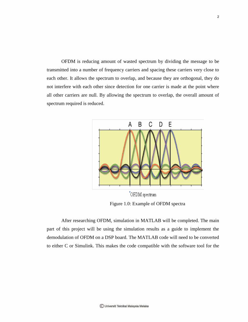
OFDM is reducing amount of wasted spectrum by dividing the message to be
transmitted into a number of frequency carriers and spacing these carriers very close to
each other. It allows the spectrum to overlap, and because they are orthogonal, they do
not interfere with each other since detection for one carrier is made at the point where
all other carriers are null. By allowing the spectrum to overlap, the overall amount of
spectrum required is reduced.
Figure 1.0: Example of OFDM spectra
After researching OFDM, simulation in MATLAB will be completed. The main
part of this project will be using the simulation results as a guide to implement the
demodulation of OFDM on a DSP board. The MATLAB code will need to be converted
to either C or Simulink. This makes the code compatible with the software tool for the
2

particular DSP board. To test the DSP code, the input and output vectors of the
MATLAB simulation and DSP implementation will be verified to correspond.
3

1.2 Objectives
The main objective for this project is to design and simulate the OFDM receiver
by using MATLAB software. The receiver will receive signal from OFDM transmitter
and will implement in DSP board.
The other objective is to improve the performance of the system using
MATLAB in different number of sub-carriers such in:
1. 853 sub-carriers
2. 1200 sub-carriers
3. 1705 sub-carriers
4

1.3 Problem statement
A common problem found in high speed communication is inter-symbol
interference (ISI). ISI occurs when a transmission interferes with itself and the receiver
cannot decode the transmission correctly.
Because the signal reflects from large objects such as mountains and building,
the receiver sees more than one copy of the signal. In communication terminology, this
is called multi-path. Since the indirect paths take more time to travel to the receiver, the
delayed copies of the signal interfere with the direct signal, causing ISI.
In DVB-T, the performance of the OFDM system will improve if we use the
higher level of the modulation. The level of modulation is the numbers of the sub-
carriers that we varied are in range 2k mode (853 until 1705)
5

1.4 Scope of Work
The scopes of the project are focuses on the design and implementation of
OFDM base band receiver for DVB-T. This project focuses on the core processing
block of receiver. This designs implement 853, 1200 and 1705 sub-carriers. Once the
receiver receive OFDM signal from the transmitter, that signal will be channeled to the
OFDM modulator using Fast Fourier Transform (FFT) technique. The sub-signals will
be merged and then will be passed trough Digital-Analog-Converter (DAC).
The digital input from transmitter will be compared to digital output
from receiver to measure the system performances. Once the signal converted into
analog waveform, it will then displays on oscilloscope. The second scope is to
implement the design to DSP hardware development board. This process is
implemented if all designs are correctly verified and simulated using particular
software.
6

CHAPTER 2
LITERATURE REVIEW
This chapter is to discuss some fundamental ideas OFDM receiver.
2.1 Background Study
The development of the Digital Video Broadcasting (DVB) standard was started
in 1993. DVB is a transmission scheme based on the MPEG-2 standard, as a method for
point to multipoint delivery of high quality compressed digital audio and video. It is an
7

enhanced replacement of the analogue television broadcast standard, as DVB provides a
flexible transmission medium for delivery of video, audio and data services.
DVB-T is a technical standard, developed by the DVB project, which specifies
the framing structure, channel coding and modulation for digital terrestrial television
(DTT) broadcasting. It is the DVB European based consortium standard for the
broadcast transmission of digital terrestrial television that first broadcast in United
Kingdom in 1997. This system transmits compressed digital audio, video and other data
in an MPEG transport stream using OFDM modulation. This type of modulation, which
uses a large number of sub-carriers, delivers a robust signal that has the ability to deal
with very severe channel conditions. There are two choices for the number of sub-
carriers known as 2k mode or 8k mode. These are actually 1705 or 6817 carriers that
are approximately 4kHz or 1kHz apart.
2.2 Digital Video Broadcasting-Terrestrial
In an OFDM scheme, a large number of orthogonal, overlapping, narrow band,
sub-channels or sub-carreirs, transmitted in parallel, divide the available transmission
bandwidth. The attraction of OFDM is mainly due to how the system handles the multi-
path interference at the receiver. A detailed description of OFDM can be found OFDM
8

transmission where we can find the expression for one OFDM symbol starting at s
tt
as follows:
(2.1)
where i
d are complex modulation symbols, Ns is the number of sub-carriers, T the
symbol duration and fc the carrier frequency. The equation (2.1) is given in the DVB-T
standard as the emitted signal. The expression is
(2.2)
where
(2.3)
9