Design and Implementation of an Electromagnetic Energy...
127
Design and Implementation of an Electromagnetic Energy Harvester for Linear and Rotary Motion Applications by Alireza Hekmati B.Sc. (Electrical Engineering), Iran University of Science and Technology, 2009 Thesis Submitted In Partial Fulfillment of the Requirements for the Degree of Master of Applied Science in the School of Engineering Science Faculty of Applied Sciences Alireza Hekmati 2013 SIMON FRASER UNIVERSITY Spring 2013
-
Upload
trinhkhanh -
Category
Documents
-
view
217 -
download
1
Transcript of Design and Implementation of an Electromagnetic Energy...

Design and Implementation of an Electromagnetic Energy Harvester for Linear and
Rotary Motion Applications
by Alireza Hekmati
B.Sc. (Electrical Engineering), Iran University of Science and Technology, 2009
Thesis Submitted In Partial Fulfillment of the
Requirements for the Degree of
Master of Applied Science
in the
School of Engineering Science
Faculty of Applied Sciences
Alireza Hekmati 2013
SIMON FRASER UNIVERSITY Spring 2013

ii
Approval
Name: Alireza Hekmati
Degree: Master of Applied Science
Title of Thesis: Design and Implementation of an Electromagnetic Energy Harvester for Linear and Rotary Motion Applications
Examining Committee: Chair: Dr. Krishna Vijayaraghavan Assistant Professor of Engineering Science
Dr. Siamak Arzanpour Senior Supervisor Assistant Professor
Dr. Carlo Menon Supervisor Associate Professor
Dr. Woo Soo Kim Internal Examiner Assistant Professor School of Engineering Science
Date Defended/Approved:
lib m-scan11
Typewritten Text
12 December 2013

iii
Partial Copyright Licence

iv
Abstract
This thesis presents a new design for an electromagnetic energy harvester to be used in
both linear and rotary motion applications. This electromagnetic energy harvester
consists of a moving coil within a fixed magnetic circuit. This magnetic circuit comprises
of a permanent magnet (as a magnetic source), a magnetic conductor (such as iron),
and an air gap to create a space for coil movement inside energy harvester setup. In the
parameter study of this electromagnetic energy harvester, it has been demonstrated that
applying design modifications will improve the amount of induced voltage by %50. For
linear motion applications, the energy harvester has been mounted on a linear motor
and the experimental results indicated that when the coil movements’ speed is 70
[mm/s], the maximum harvested power is 5.320 [mW].
For rotary motion applications, first a voice coil speaker has been used as a single
degree of freedom system to produce voltage through a rotating beam and hub. Since in
lower resonance frequencies, the maximum induced voltage is quite low, thus in next
step, the two degrees of freedom energy harvesting system for rotary motion
applications has been introduced. This system has been mounted on a car ring and the
result illustrated that at the resonance frequency (15 [Hz]), the induced voltage was
0.175 [V] for each coil.
Keywords: Electromagnetic energy harvester; Linear motion; Rotary motion; Permanent magnet; Magnetic conductor

v
Dedication
I dedicate my thesis to my lovely family,
specially my mother, who her support and
kindness through all the stages of my life made
my goals so much easier to achieve.

vi
Acknowledgements
I would like to thank my supervisor, Dr. Arzanpour, for his great support, useful
guidance, and excellent understanding during my graduate study, which made this part
of my lifetime so much effective and beneficial. His encouragements helped me a lot
through my difficult times during my research. I would also like to thank Dr. Menon and
Dr. Kim for kindly reviewing my thesis.
Also, I would like to thank Ehsan Asadi, my colleague and my friend, who has helped me
so much during diverse stages of my research and aided me to overcome the obstacles
in my research progress more easily.
Finally, I would like to thank all of my friends, specially Ehsan Seyedin, who has always
been there for me and supported me through my difficult times.

vii
Table of Contents
Approval .......................................................................................................................... ii Partial Copyright Licence ............................................................................................... iii Abstract .......................................................................................................................... iv Dedication ....................................................................................................................... v Acknowledgements ........................................................................................................ vi Table of Contents .......................................................................................................... vii List of Tables .................................................................................................................. ix List of Figures.................................................................................................................. x
1. Introduction .......................................................................................................... 1 1.1. Thesis Objective and Thesis Outline ...................................................................... 7
2. The main governing theory of Electromagnetic Generators ............................. 9 2.1. Boundary conditions for magnetic field vectors ..................................................... 11 2.2. Calculation of magnetic flux density (B) for permanent magnet used in the
energy harvesting setup ....................................................................................... 14 2.2.1. Curl of a vector field .................................................................................. 14 2.2.2. Vector magnetic potential .......................................................................... 15 2.2.3. Magnetization and equivalent current densities ......................................... 16 2.2.4. Magnetic flux density (B) calculation ......................................................... 17
3. THE PARAMETER STUDY OF ELECTROMAGNETIC ENERGY HARVESTER ....................................................................................................... 23
3.1. The modified voice coil energy harvester structure and simulation analysis ......... 23 3.2. Analyzing the sinusoidal base excitation vibration through shaker setup .............. 29
3.2.1. Simulation analysis of sinusoidal base excitation vibration ........................ 29 3.2.2. Experimental analysis of sinusoidal base excitation vibration .................... 31 3.2.3. Analyzing the effect of design modifications for energy harvester
setup through simulation ........................................................................... 33 3.3. Experimental analysis of linear motion electromagnetic energy harvester
with diverse velocities through linear motor setup ................................................. 35 3.3.1. Describing the experimental setup for linear motion .................................. 35 3.3.2. Parameter study of energy harvester when iron cylinder has its
primary length ........................................................................................... 37 3.3.3. Parameter study of energy harvester when iron cylinder has half of
its primary length....................................................................................... 41 3.3.4. Parameter study of energy harvester when iron cylinder has one
third of its primary length ........................................................................... 46 3.3.5. Parameter study of energy harvester when iron cylinder has quarter
of its primary length ................................................................................... 50 3.3.6. Parameter study of energy harvester when iron cylinder has one
fifth of its primary length ............................................................................ 54 3.3.7. Parameter study of energy harvester when iron cylinder has one
sixth of its primary length .......................................................................... 58 3.3.8. Parameter study of energy harvester when there is no iron cylinder ......... 62

viii
3.3.9. Conclusion ................................................................................................ 65 3.4. Experimental analysis when the iron core has no tooth-shape edges ................... 68
3.4.1. Parameter study of energy harvester when iron cylinder has its primary length (iron core has no tooth-shape edges) ................................ 68
3.4.2. Parameter study of energy harvester when iron cylinder has one sixth length of its primary length (iron core has no tooth-shape edges) ....................................................................................................... 71
3.4.3. Parameter study of energy harvester when there is no iron cylinder (iron core has no tooth-shape edges)........................................................ 75
3.4.4. Conclusion ................................................................................................ 78
4. One Degree of Freedom Electromagnetic Energy Harvester System for Rotary Motion ..................................................................................................... 84
4.1. Mathematical Model of One Degree of Freedom Rotating Harvester .................... 84 4.1.1. Mechanical Subsystem Model ................................................................... 85 4.1.2. Electrical Subsystem Model ...................................................................... 89
4.2. Numerical analysis of one degree of freedom rotating harvester .......................... 90 4.3. Experimental test of one degree of freedom rotating harvester ............................. 93 4.4. Conclusion ........................................................................................................... 95
5. Two Degree of Freedom Electromagnetic Energy Harvester System for Rotary Motion ..................................................................................................... 96
5.1. Describing the Two Degree of Freedom Rotating Harvester System .................... 96 5.2. System Identification of the Two Degree of Freedom Rotating Harvester ............. 97
5.2.1. Governing Equations on Base Excitation Case ......................................... 97 5.2.1.1. Examining the Two Degree of Freedom Rotating Harvester
when the Connecting Spring is Soft ..................................................... 98 5.2.1.2. Examining the Two Degree of Freedom Rotating Harvester
when the Connecting Spring is Stiff ..................................................... 99 5.3. Testing the two degree of freedom energy harvesting system on rotary
application .......................................................................................................... 100 5.3.1. The governing equations on rotary motion case ...................................... 100 5.3.2. Numerical analysis of two degree of freedom rotating harvester ............. 102 5.3.3. Experimental result of two degree of freedom rotating harvester ............. 103
6. Conclusion ........................................................................................................ 107
References ................................................................................................................. 109

ix
List of Tables
Table 1. The effect of slope at the end of iron cylinder on induced voltage ................ 81
Table 2. The effect of internal coil resistance on induced voltage .............................. 82
Table 3. The maximum harvested power for both coils .............................................. 83
Table 4. Characteristics of the experimental beam-mass system ............................... 93

x
List of Figures
Figure 1. Closed path about the interface of two media to determine the boundary condition ...................................................................................... 13
Figure 2. (a) The magnetization of permanent magnet which has been used in energy harvester setup; (b) the permanent magnet itself ............................. 17
Figure 3. A small circular loop carrying current I equivalent to surface current density on the side wall of the permanent magnet ....................................... 19
Figure 4. The main parts of the modified voice coil energy harvester .......................... 24
Figure 5. The effect of conical end of iron core on magnetic losses ............................ 25
Figure 6. The effect of tooth-shape edges of iron core on magnetic field in air gap .............................................................................................................. 26
Figure 7. The effect of slope at the end of iron cylinder on magnetic losses ................ 27
Figure 8. The B-H curve for permanent magnet [59] ................................................... 28
Figure 9. Magnetic flux density streamline for primary design of electromagnetic energy harvester when iron core has conical end, has tooth-shape edges on it, and iron cylinder has slope at its end ........................................ 29
Figure 10. Induced voltage vs. Initial position of the coil: simulation result .................... 31
Figure 11. The shaker experimental setup .................................................................... 32
Figure 12. Induced voltage vs. Initial position of the coil: experimental result ................ 32
Figure 13. Simulation analysis of three different design parameters ............................. 34
Figure 14. Schematic configuration of the experimental setup for linear motion ............ 36
Figure 15. Demonstrating diverse lengths of iron cylinder: (a) Original length; (b) Half length; (c) One fifth length; (d) One sixth length .................................... 37
Figure 16. The coil resistance effect on induced voltage with respect to diverse velocities: (a) coil resistance is 692 [Ω]; (b) coil resistance is 20.4 [Ω] ......... 38
Figure 17. The coil resistance effect on harvested power with respect to diverse load resistors: (a) coil resistance is 692 [Ω]; (b) coil resistance is 20.4 [Ω] ............................................................................................................... 39
Figure 18. The equivalent electrical circuit for energy harvester setup with variable load resistors .................................................................................. 40

xi
Figure 19. Comparison between numerical analysis and experimental result for load powers with respect to variable load resistors ...................................... 41
Figure 20. Effect of slope at the end of iron cylinder on induced voltage when iron cylinder has the half of its primary length .............................................. 42
Figure 21. The coil resistance effect on induced voltage when iron cylinder has half of its primary length ............................................................................... 43
Figure 22. The coil resistance effect on harvested power when iron cylinder has half of its primary length: (a) coil resistance is 692 [Ω]; (b) coil resistance is 20.4 [Ω] ................................................................................... 45
Figure 23. Comparison between numerical analysis and experimental result for load powers with respect to variable load resistors when iron cylinder has half of its primary length ........................................................................ 46
Figure 24. Effect of slope at the end of iron cylinder on induced voltage when iron cylinder has the one third of its primary length ...................................... 47
Figure 25. The coil resistance effect on induced voltage when iron cylinder has one third of its primary length ....................................................................... 48
Figure 26. The coil resistance effect on harvested power when iron cylinder has one third of its primary length: (a) coil resistance is 692 [Ω]; (b) coil resistance is 20.4 [Ω]. .................................................................................. 49
Figure 27. Comparison between numerical analysis and experimental result for load powers with respect to variable load resistors when iron cylinder has one third of its primary length ................................................................ 50
Figure 28. Effect of slope at the end of iron cylinder on induced voltage when iron cylinder has the quarter of its primary length ......................................... 51
Figure 29. The coil resistance effect on induced voltage when iron cylinder has quarter of its primary length ......................................................................... 52
Figure 30. The coil resistance effect on harvested power when iron cylinder has quarter of its primary length: (a) coil resistance is 692 [Ω]; (b) coil resistance is 20.4 [Ω] ................................................................................... 53
Figure 31. Comparison between numerical analysis and experimental result for load powers with respect to variable load resistors when iron cylinder has quarter of its primary length ................................................................... 54
Figure 32. Effect of slope at the end of iron cylinder on induced voltage when iron cylinder has the one fifth of its primary length ....................................... 55
Figure 33. The coil resistance effect on induced voltage when iron cylinder has one fifth of its primary length ........................................................................ 56

xii
Figure 34. The coil resistance effect on harvested power when iron cylinder has one fifth of its primary length: (a) coil resistance is 692 [Ω]; (b) coil resistance is 20.4 [Ω] ................................................................................... 57
Figure 35. Comparison between numerical analysis and experimental result for load powers with respect to variable load resistors when iron cylinder has one fifth of its primary length ................................................................. 58
Figure 36. Effect of slope at the end of iron cylinder on induced voltage when iron cylinder has the one sixth of its primary length ...................................... 59
Figure 37. The coil resistance effect on induced voltage when iron cylinder has one sixth of its primary length ...................................................................... 60
Figure 38. The coil resistance effect on harvested power when iron cylinder has one sixth of its primary length: (a) coil resistance is 692 [Ω]; (b) coil resistance is 20.4 [Ω] ................................................................................... 61
Figure 39. Comparison between numerical analysis and experimental result for load powers with respect to variable load resistors when iron cylinder has one sixth of its primary length ................................................................ 62
Figure 40. The coil resistance effect on induced voltage when there is no iron cylinder ........................................................................................................ 63
Figure 41. The coil resistance effect on harvested power when there is no iron cylinder: (a) coil resistance is 692 [Ω]; (b) coil resistance is 20.4 [Ω] ............ 64
Figure 42. Comparison between numerical analysis and experimental result for load powers with respect to variable load resistors when there is no iron cylinder ................................................................................................. 65
Figure 43. The induced voltage and harvested power based on diverse lengths of iron cylinder: (a) induced voltage for both coils; (b) harvested power for both coils ................................................................................................ 67
Figure 44. The coil resistance effect on induced voltage when iron core has no tooth-shape edges ....................................................................................... 69
Figure 45. The coil resistance effect on harvested power when iron core has no tooth-shape edges: (a) coil resistance is 692 [Ω]; (b) coil resistance is 20.4 [Ω] ........................................................................................................ 70
Figure 46. Comparison between numerical analysis and experimental result for load powers with respect to variable load resistors when iron core has no tooth-shape edges .................................................................................. 71
Figure 47. Effect of slope at the end of iron cylinder on induced voltage when iron cylinder has the one sixth of its primary length and iron core has no tooth-shape edges .................................................................................. 72

xiii
Figure 48. The coil resistance effect on induced voltage when iron core has no tooth-shape edges and iron cylinder has one sixth of its primary length........................................................................................................... 73
Figure 49. The coil resistance effect on harvested power when iron core has no tooth-shape edges and iron cylinder has one sixth of its primary length: (a) coil resistance is 692 [Ω]; (b) coil resistance is 20.4 [Ω] .............. 74
Figure 50. Comparison between numerical analysis and experimental result for load powers with respect to variable load resistors when iron core has no tooth-shape edges and iron cylinder has one sixth of its primary length........................................................................................................... 75
Figure 51. The coil resistance effect on induced voltage when iron core has no tooth-shape edges and there is no iron cylinder ........................................... 76
Figure 52. The coil resistance effect on harvested power when iron core has no tooth-shape edges and there is no iron cylinder: (a) coil resistance is 692 [Ω]; (b) coil resistance is 20.4 [Ω] .......................................................... 77
Figure 53. Comparison between numerical analysis and experimental result for load powers with respect to variable load resistors when iron core has no tooth-shape edges and there is no iron cylinder ...................................... 78
Figure 54. The induced voltage and harvested power based on diverse lengths of iron cylinder when iron core has no tooth-shape edges: (a) induced voltage for both coils; (b) harvested power for both coils ............................. 80
Figure 55. One degree of freedom system for harvesting energy from rotary motion application ........................................................................................ 85
Figure 56. Frequency response of induced voltage which caused by relative displacement between permanent magnet and magnetic coil of voice coil speaker ................................................................................................. 91
Figure 57. Spring constant effect on frequency response for one degree of freedom system ........................................................................................... 92
Figure 58. The effect of load mass distribution on frequency response of one degree of freedom electromagnetic rotary energy harvester ........................ 93
Figure 59. Frequency response of induced voltage - Experimental result for one degree of freedom system ........................................................................... 94
Figure 60. Two degrees of freedom system for harvesting energy from rotary motion application ........................................................................................ 97
Figure 61. The frequency responses of: (a) first linear voice coil motor, and (b) second linear voice coil motor; when the connecting spring is soft ............... 98

xiv
Figure 62. The frequency responses of: (a) first linear voice coil motor, and (b) second linear voice coil motor; when the connecting spring is stiff ............... 99
Figure 63. Simulation result for two degrees of freedom system ................................. 102
Figure 64. Simulation result of harvested power for two degrees of freedom system ....................................................................................................... 103
Figure 65. The schematic of the experimental setup for two degrees of freedom system: (a) the general setup; (b) details of energy harvester components ............................................................................................... 105
Figure 66. Frequency response of induced voltage - Experimental result ................... 106

1
1. Introduction
Energy harvesting refers to all the methods which enable us to convert diverse
forms of kinetic energy into the storable form of electrical energy to power a standalone
sensor and/or actuator system. Energy harvesting is an attractive research subject as
inexhaustible replacements for batteries in low-power devices to convert ambient energy
into electrical energy and have received growing research interest in recent years.
Ambient energy is the energy which is available in the environment and is not
stored explicitly [1]. The most common used ambient energy sources to harvest are
essentially of three forms: light (solar power), thermal gradient, and mechanical energy
from movement and vibration (motion) [1]–[3]. These sources can be used as either a
direct replacement or to augment the battery to increase both the lifetime and capability
of the network [4]-[6]. There are other alternative solutions such as micro fuel cells [7]
and micro turbine generators [8]. Although these two sources both involve the use of
chemical energy and require refuelling when their supplies are exhausted, but such
systems are capable of producing high levels of energy and power density and
demonstrate good potential to recharge batteries [9].
Solar power, which is used by photovoltaic, is probably the most well known
amongst the other sources. The power density of solar cells in direct sunlight is
excellent, but it is limited in dim ambient light conditions. Moreover, solar cells are clearly
unsuitable in applications where the cells can be obscured by contamination, or simply
where no light may be present.
Thermal energy is another source which can be directly converted to electrical
energy through thermoelectric effect called the Seebeck effect. early thermoelectric
microgenerators produced just a few nanowatts [10], however, the output power has
been improved to around 1 microwatt when it is combined with micro-combustion
chambers recently [11,12].

2
Kinetic energy is one of the sources that is typically present in the form of
vibrations, rotations, random displacements, or forces. it can potentially be converted
into electrical energy using various energy harvesting techniques, such as
electromagnetic, piezoelectric, or electrostatic mechanisms.
Electrostatic energy harvesting relies on the relative movement between
electrically isolated charged capacitor plates to generate energy based on the changing
capacitance of vibration dependant variable capacitor [13]. If the voltage across the
capacitor is constrained, charge will move from the capacitor as the capacitance
decreases while if the charge on the capacitor is constrained, the voltage will increase
as the capacitance decreases [14]. In both cases, mechanical energy is transformed into
electrical energy. Generally the voltage constrained method offers more energy than the
charge constrained approach, but by incorporating a parallel capacitor to the energy
harvesting capacitor, the energy from the charge constrained system can approach that
of the voltage constrained system as the parallel capacitance approaches infinity. This
parallel capacitor constrains the voltage on the energy harvesting capacitor [15].
However, one of the disadvantages of this method is that it requires an additional
voltage source or charge source, which can be a rechargeable battery or pre-charged
capacitor, to initiate the conversion process. On the other hand, the significant
advantage of using the electrostatic converter is its ability to integrate with
microelectronics and it does not need any smart material.
Electrostatic generators can be classified into three types [16]:
1. In-plane overlap varying;
2. In-plane gap closing;
3. Out-of-plane gap closing.
Roundy [17] mentions that in-plane gap closing represents the highest power
output with an optimized design harvesting 100 microwatts per cubic centimeter, while
out-of-plane gap closing is the next highest followed by in-plane overlap varying.
To illustrate research works which have been conducted in these three types,
Meninger et al [18] simulated an in-plane overlap varying electrostatic generator and
generated 8 microwatts from 2.5 [kHz] input motion.

3
Despesse [19] describes an electrostatic in-plane gap closing structure with a
charge constrained cycle. This device has an 18 cubic centimeters volume and
produced 1052 microwatts scavenged power for a 90 micrometers vibration amplitude at
50 [Hz]. This amount of power represents a scavenged efficiency of 60% with the
charge/discharge losses and transduction losses being accounted for.
Miyazaki [20] showed an out-of-plane cantilever based generator with a base
capacitance of 1 [nF] and a variable capacitance of between 30 [pF] and 350 [pF]. The
device resonated at 45 [Hz] and was tested on a wall with a 1 [μm] displacement up to
100 [Hz]. 120 [nW] was harvested from this configuration.
There are some other generator categories which employ charged electrets.
Sterken [21,22] presents a concept of an in-plane, overlap varying, voltage constrained,
variable capacitor polarized with a SiO2/Si3Ni4 electret; while Arakawa [23]
demonstrates another in-plane, overlap varying, voltage constrained, variable capacitor
polarized with a fluorocarbon polymer electret offering high dielectric strength. For a 1
[mm] displacement amplitude at 10 [Hz], a 20 mm × 20 mm × 2 mm device produces 6
[μW] at 200 [V] into an optimized external resistive load of [Ω]. in another study,
Peano [24] demonstrates an electret-based in-plane overlap varying surface
micromachined structure numerically and illustrates that nonlinear behaviour of the
converter is crucial in the generator optimization and has to be taken into account. 50
[μW] power is predicted from a 911 [Hz] vibration source moving 5 [μm], while the same
device optimized with a linear model is expected to produce only 5.8 [μW] power.
Piezoelectric energy harvesting converts mechanical energy to electrical by
straining a piezoelectric material [25]. When a piezoelectric material is placed under a
mechanical stress, a charge separation will occur across the material and will produce
voltage, which is proportional to the applied stress. Piezoelectric materials usually show
anisotropic characteristics, hence material properties differ depending upon the force
direction and orientation of the polarization and electrodes [26]. These piezoelectric
materials are available in diverse forms, such as single crystal like quartz, piezoceramic
like lead zirconate titanate or PZT, thin film like sputtered zinc oxide, screen printable
thick-films based upon piezoceramic powders, and polymeric materials like
polyvinylidenefluoride (PVDF) [27]-[29]. The advantage of using piezoelectric converter
810

4
is the direct generation of desired voltage since it does not need a separate voltage
source and additional components. Moreover, these converters are simple and can be
used in force and impact-coupled harvesting applications. Some disadvantages are that
piezoelectric materials are brittle in nature and sometimes allow the leakage of charge.
Thus the transduction efficiency is limited [30]. Another disadvantage is that the
piezoelectric generator should vibrate at its resonant frequency in order to generate
maximum power. The resonant frequency is related to elastic constant for the
piezoelectric material, the mechanical mass and its shape [31]. However, these
parameters cannot be changed after the system is built. Therefore, the piezoelectric
generator can only generate the maximum power when the driving frequency is equal to
the system’s natural frequency.
The earliest example of a piezoelectric kinetic energy harvesting system extracts
energy from impacts, therefore it is called an impact coupled device. Initial work
demonstrates the feasibility of this approach by dropping a 5.5 [g] steel ball bearing from
20 [mm] onto a piezoelectric transducer [32]. The piezoelectric transducer consists of a
19 [mm] diameter, 0.25 [mm] thick piezoelectric ceramic bond to a bronze disc 0.25
[mm] thick with a diameter of 27 [mm]. This work determines that the optimum efficiency
of the impact excitation approach is 9.4% into a resistive load of 10 [kΩ].
The piezoelectric generators have also been used to power human-wearable
systems. Human motion is characterized by large amplitude movements at low
frequencies. A device has been developed at the Massachusetts Institution of
Technology (MIT) in the 1990s [33]. Researchers first mounted an 8 layer stack of PVDF
laminated with electrodes either side of a 2 [mm] thick plastic sheet. This stave was used
as an insole in a sports training shoe. At a frequency of 0.9 [Hz], this arrangement
produced an average power of 1.3 [mW] into a 250 [kΩ] load.
A cantilever structure with piezoelectric material attached to the top and bottom
surfaces is an attractive geometry for harvesting energy from vibrations, where these
structures are designed to operate in a bending mode. A tapered cantilever beam was
developed by Glynne- Jones et al [34]–[36]. For a given displacement, the tapered
profile ensures a constant strain in the piezoelectric film along its length. The generator
was fabricated by screen printing a piezoelectric material onto a 0.1 [mm] thick hardened

5
AISI 316 stainless steel. The piezoelectric material is based upon PZT-5H powder
blended with Corning 7575 glass and a suitable thick-film vehicle to form a screen
printable thixotropic paste [37]. The structure operated in its fundamental bending mode
at a frequency of 80.1 [Hz] and produced up to 3 [μW] of power into an optimum resistive
load of 333 [kΩ]. Recent advances in the film properties can also improve power output
[38].
Another type of piezoelectric harvester is a MEMS cantilever device which has
been presented by Jeon et al [39]. The cantilever was formed from a membrane made
from layers of thermally grown silicon oxide, deposited silicon nitride and sol–gel
deposited zirconium dioxide which acts as a buffer layer. The novelty of this work was
mainly based on the use of a Ti/Pt electrode pattern e-beam evaporated and patterned
on top of the PZT later. This generator was found to have a resonant frequency of 13.9
[kHz] at which it produced 1.01 [μW] at 14 [nm] base displacement.
At last, Sodano et al also compared macro-fibre composite (MFC) actuators with
standard piezoceramics [40, 41]. The MFC structure was developed by NASA [42] and
consists of thin PZT fibres embedded in a Kapton film. The MFC was found to supply too
little current to charge batteries while the standard PZT piezoceramic was able to charge
various capacity nickel metal hydride batteries.
Electromagnetic induction, first discovered by Faraday in 1831, involves the
generation of electric current in a conductor located within a magnetic field. The
conductor typically takes the form of a coil and the induced voltage is generated by
either the relative motion of the magnet and coil, or because of changes in the magnetic
field with time. In the former case, the amount of generated induced voltage depends
upon the magnetic field intensity, the velocity of the relative motion and the length of the
coil [43].Voice coils that are originally designed as loudspeakers are one of the
candidates for this application. Unlike electrostatic mechanism, no separate voltage
source is needed to get the conversion process started. Moreover, the system can be
designed without mechanical contact between any parts, which can be lead to improve
reliability and to reduce mechanical damping [44]. Even in the theory, this type of
converter could be designed so that the value of mechanical damping is small.

6
Considering the drawbacks of both electrostatic and piezoelectric mechanisms, the
electromagnetic converter has been examined in detail in this thesis.
The vibration sources can be found in diverse applications such as household
goods (fridges, washing machines, microwave ovens etc.), industrial plant equipment,
moving systems like automobiles and airplanes, and structures such as buildings and
bridges [45], thus the advantage of using mechanical vibration to harvest energy is that
this type is the most prevalent energy source available in many environments. The
generated amount of energy by this approach depends upon the efficiency of the
generator and the power conversion electronics and the quantity and form of the kinetic
energy available in the environment. Amirtharajah and Chandrakasan [1] has described
a self-powered Digital Signal Processing system, which powered by an electromagnetic
generator. Their generator consists of a cylindrical housing in which a cylindrical mass is
attached to a spring and fixed to one end. Moreover, a permanent magnet is attached to
the other end of the housing and a coil attached to the mass, which is free to oscillate
vertically within the housing. The resonant frequency of their design was 94 [Hz] and the
maximum output voltage was 180 [mV]. The authors simulated the generator output in a
human-powered application and predicted that an average of 400 [µW] could be
generated from 2 [cm] movement at 2 [Hz].
Glynne-Jones et al. [46] has described a cantilever-based prototype with a four
magnet and fixed coil arrangement with the overall volume of 3.15 [ 3cm ] and the
resonant frequency of 106 [Hz]. At an acceleration level of 2.6 [ 2sm
], the generator
produced an output voltage of 1 [V]. The generator was mounted on the engine block of
a car and the maximum peak power of 4 [mW] was produced, while the average power
was 157 [µW] over a journey of 1.24 [km].
Von Buren and Troster [47] have described a linear electromagnetic generator,
which is designed to be driven by human motion. The design consists of a tubular
translator which contains a number of cylindrical magnets separated by spacers. The
translator moves vertically within a series of stator coils. The stator and translator
designs were realised with six magnets and five coils, with the total device volume of
30.4 [ 3cm ]. The fabricated prototype produced an average power output of 35 µW when

7
located just below a subject’s knee. Williams and Yates [48] have developed a micro-
electromagnetic converter. They drove this converter with vibration of 50 [µm] magnitude
at 330 [Hz] and generated 1 [mW] power from it.Lastly, Hadas et al. [49] have developed
an electromagnetic vibration powered generator, which is concerned with wireless
aircraft-monitoring systems. The presented device is 45 [3cm ] in volume, resonates at
34.5 [Hz] and delivers around 3.5 [mW] from 3.1 [ 2/ sm ] acceleration levels.
Note that there are other methods to harvest energy, such as using
magnetostrictive materials which deform when placed in a magnetic field and conversely
if strained can induce changes in a magnetic field. These materials can be used
independently but typically have been employed in piezoelectric-magnetostrictive
composites. Bayrashev et al fabricated a diameter of 0.5 [mm] thick PZT disc
sandwiched between 1.5 [mm] thick Terfenol discs [50]. When the laminate is exposed
to a low frequency varying magnetic field, the PZT layer was strained and a charge
generated. Power output was found to be between 10 and 80 [μW] depending upon the
distance between the magnet and the composite.
1.1. Thesis Objective and Thesis Outline
Rotary motion is one of the most commonly used forms of mechanical motion
and power transmission widely used in various platforms in civil and industrial
applications. Wireless communication is used in rotary devices as a reliable technique
for sensory data acquisition, which does not have the drawbacks of wired systems such
as the need for slip-rings. In those applications, a main problem is providing energy to
power sensors and wireless modules. Although new technologies have considerably
improved the size and power storage of batteries, they still need to be charged when
used continuously. As a result, availability of a power scavenging unit will be a huge
advantage in modern wireless systems. The main objective of this thesis is to develop a
reliable electromagnetic energy harvester for rotary applications to locally generate the
required power for the electronic systems.

8
chapter 2 illustrates the main governing theory of electromagnetic for electrical
part of the energy harvester structure to get basic understanding of the design
procedure.
The basic design concept of electromagnetic energy harvester for both linear and
rotary motion applications is the same and is based on moving coil within a fixed
magnet, where the moving coil cuts the magnetic flux density around the permanent
magnet to induce voltage within it.
Basically, the generalized linear electromagnetic energy harvester is inspired by
voice coil. The voice coils are originally designed for high frequency applications like
laud speakers, and their usage for low frequency applications, like energy harvesting,
have not been examined properly. Therefore, investigating the effects of changing some
parameters in traditional voice coil structure, such as the length of the device or
reshaping some parts of the device, is the main purpose of the third chapter of this
thesis. The goal of chapter 3 is to provide a parameter study to improve the power
efficiency of the electromagnetic linear harvesters.
Considering the same design concept as linear generator, another
electromagnetic energy harvester has been developed and implemented for rotary
motion applications. Chapter 4 discusses a rotary power scavenging unit comprised of a
rotating flexible cantilever beam with a voice coil as the tip mass for energy harvesting.
The gravitational force on the tip mass causes sustained oscillatory motion in the flexible
beam as long as there is rotary motion. Note that in this one degree of freedom system
and the resonance frequency occurs in relatively high frequencies, which are not
achievable in many rotary applications, therefore it has been tried to reduce the
resonance frequency of the system. But since in lower resonance frequencies, the
maximum induced voltage has decreased dramatically, therefore in chapter 5, the two
degrees of freedom energy harvesting system for rotary motion applications has been
introduced. In chapter 5, after representing the mathematical modeling of the two
degrees of freedom energy harvester system, based on the shaker test results, the
characteristics of this generator have been described. Finally, this rotary energy
harvester has been mounted on a car’s ring to demonstrate the its power generation
capability in practice.

9
2. The main governing theory of Electromagnetic Generators
Kinetic energy harvesting requires a transduction mechanism to generate
electrical energy from motion and the generator will require a mechanical system that
couples environmental displacements to the transduction mechanism. Since in this
thesis the electromagnetic mechanism has been chosen for generating electrical power,
thus in this chapter, the governing equations of electromagnetic theory has been
described.
The basic theory of an electromagnetic energy harvester is based on Faraday’s
law, which relates the electromotive force (ε ) to the rate of change of flux linkage (φ )
as [51],
t∂∂
−=φε (1)
The negative sign in the Faraday’s law is an assertion that the current induced by
electromotive force (emf) will be in a direction to oppose the changes in the linking
magnetic flux.
The electromotive force (emf) can be obtained from taking the line integral of
electric field (E) over contour C [52];
∫= CldE
.ε (2)
and the flux linkage can be obtained from taking the surface integral of magnetic
flux density (B) over surface S [53];

10
∫= SdsnB ˆ.
φ
(3)
On the other hand, when a conductor with a velocity of u, moves in a static
magnetic field with a flux density of B, the magnetic force applied on conductor is [54],
BquFm ×= (4)
This force causes the electrons in the conductor to drift toward one end of the
conductor and hence leave the other end charged positively. This separation of charges
continues until equilibrium state is reached. At the equilibrium state, the net force on the
charges in the moving conductor is equal to zero.
The magnetic force per unit charge can be interpreted as an induced electric field
along the conductor that produces a voltage, which can be calculated through the
following equation:
dlBuV ).(∫ ×= (5)
This induced voltage is referred to as a flux cutting emf or a motional emf.
Equation (5) indicates that to maximize the induced voltage in the circuit, the direction of
the moving conductor should be perpendicular to the direction of the magnetic field, and
the result vector of )( Bu× should be in the same direction as differential length along
the length of the conductor. Therefore, the Faraday’s law can be rewritten as [55],
∫∫∫ ×+∂∂
−=CSC
dlBudstBdlE ).(..
(6)
According to equation (6), the time variation of magnetic flux density and/or a
moving circuit with a velocity u in a magnetic field produces electric field that can induce
11
current in an electrical conductor in a closed circuit configuration. Since there is no time-
varying magnetic field in designed electromagnetic energy harvester, the first term on
the right hand side of (6) is equal to zero. Therefore, only the second term on the right
hand side of (6), which presents a moving conductor in a static magnetic field, induces
voltage in the coil.
2.1. Boundary conditions for magnetic field vectors
Prior to solving the magnetic problems, the pattern for how the magnetic flux
density (B) and magnetic field intensity (H) will change when they cross the boundary
between the two different media that have different magnetic properties, is needed. The
boundary conditions are determined by applying the integral form of Maxwell’s equations
to a small cylinder and a small closed path at an interface of the two media.
The boundary condition for the normal component of magnetic flux density (B) is
obtained from divergence equation, which is [55]:
0. =∫S dsB
(7)
In general, the application of the integral form of a divergence equation to a
shallow cylinder at an interface with top and bottom faces in the two contiguous media
yields the boundary condition for the normal component; and the application of the
integral form of a curl equation to a flat closed path at a boundary with top and bottom
sides in the two touching media gives the boundary condition for the tangential
component. From the divergenceless nature of the magnetic flux density (B) field, it can
be concluded that the normal component of B is continuous across an interface [55]:
nn BB 21 = (8)
where nB1 is the normal component of B in media 1 (iron), and nB2 is the normal
component of B in media 2 (air), as shown in figure 1.

12
The magnetic flux density (B) quantity is the only vector needed to study
magnetostatics in free space, but in other materials it is convenient to define another
vector field, which is called the magnetic field intensity (H). The purpose of defining the
magnetic field intensity (H) vector is to account for the effect of magnetization, which is a
vector to define the macroscopic effect of magnetic materials in a magnetic field. For
homogenous media:
HB µ= (9)
where µ is the permeability of media. Therefore (8) becomes [55]:
nn HH 2211 µµ = (10)
The boundary condition for the tangential component of the magnetic field
intensity (H) can be obtained from [56]:
dstDJdlH
SC).(. ∫∫ ∂
∂+=
(11)
where J is the density of free currents, and the term tD ∂∂ / is called
displacement current density, which is necessary to make (11) consistent with the
principle of conservation of charge.

13
Figure 1. Closed path about the interface of two media to determine the boundary condition
The closed path abcda in figure (1) is chosen as the contour C. Letting bc = da =
Δh approach zero, then,
Sn JHHa =−× )( 212 (12)
where 2na is the outward unit normal from medium 2 (air) at the interface, and
sJ is the surface current density on the interface normal to the contour C. Thus, the
tangential component of the H field is discontinuous across an interface where a free
surface current exists, and the amount of discontinuity is determined by (12). It should
be mentioned that sJ exists only when an interface with an ideal perfect conductor or a
superconductor is assumed, otherwise sJ is zero. Therefore, the tangential component
of H is continuous across the boundary of almost all physical media. Equations (8) and
(12) are the boundary conditions which are used in simulation process.

14
2.2. Calculation of magnetic flux density (B) for permanent magnet used in the energy harvesting setup
In order to calculate the magnetic flux density (B) of the permanent magnet,
some concepts should be defined first. But before proceeding, keep in mind that an
exact analysis of magnetic circuits is very difficult to achieve, since:
1. Accounting for leakage fluxes (fluxes which stray or leak from the main flux
paths of a magnetic circuit) is really a difficult approach;
2. The fringing effect which causes the magnetic flux lines at the air gap to
spread is hard to capture;
3. The permeability (µ) of ferromagnetic materials depends on magnetic field
intensity (H); that is, magnetic flux density (B) and magnetic field intensity (H) have a
nonlinear relationship.
2.2.1. Curl of a vector field
In general, there are two kinds of field sources: flow source, and vortex source.
The vortex source causes a circulation of a vector field. This circulation of a vector field
around a closed path is defined as the scalar line integral of the vector over the path, as
shown below [55]:
Circulation of X around contour C ∫≡ CdlX . (13)
Equation (13) is a mathematical definition and its physical meaning depends on
the type of the field which the vector X represents. As an example, if X is magnetic field
intensity, then the circulation will be a current around the closed path. Since circulation
as defined in equation (13) is a line integral of a dot product, thus its value depends on
the orientation of the contour C relative to the vector X. In order to define a point function
for measuring the strength of a vortex source, contour C should be made very small and
its orientation should maximize the circulation. Therefore, the curl of a vector field,
denoted by X×∇ , is defined as follows [55]:

15
].[ max1
lim0
∫∆→∆
≡×∇ C dlXnaSS
X
(14)
where area ΔS is bounded by contour C and na is the vector normal to that
area, which its direction follows the right-hand rule; that is when the fingers of the right
hand follow the direction of dl, the thumb points to the na direction.
It can be shown that in spherical coordinate system, the curl of a vector field (X)
can be calculated through following equation:
φθθφθ
θφθ
θXRRXRX
R
RaRaRa
RX
sin
sin
sin21
∂∂
∂∂
∂∂
=×∇ (15)
2.2.2. Vector magnetic potential
Since the magnetic flux density (B) is in a solenoid, it can be expressed as the
curl of another vector field, like A, as determined below [57]:
AB ×∇= (16)
where the vector field A is called the vector magnetic potential. It can be proven
that this vector magnetic potential (A) of a point at a distance R from a volume current
density (J) can be calculated through following equation:
(17) ∫= v dvRJA )()4( 0 πµ

16
where 0µ is the permeability of free space, and v is the volume where volume
current density (J) has been distributed on it.
2.2.3. Magnetization and equivalent current densities
As mentioned before, magnetization is a vector to define the macroscopic effect
of magnetic materials in a magnetic field. Magnetization is caused by electrons of atoms
which are the basic components of all materials. These orbiting electrons cause
circulating currents and form microscopic magnetic dipoles. When there is no external
magnetic field, the magnetic dipoles of the atoms of most materials (except permanent
magnets) have random orientations, which resulting in no magnetic moment in total. But
applying an external magnetic field to materials causes the magnetic moments of the
spinning electrons to align. Moreover, due to a change in the orbital motion of electrons,
magnetic moment is going to induce in the material. To determine the quantitative
change in the magnetic flux density caused by magnetic material presence, assume k
m
is the magnetic dipole moment of an atom. Suppose there are n atoms per unit volume
in the material, a magnetization vector (M) is defined as [58]:
(18)
which represents the volume density of the magnetic dipole moment. It can be
proven that the effect of the magnetization vector can be interpreted as both a volume
current density (m
J ) and a surface current density (ms
J ), as demonstrated in the
following equations, respectively.
(19)
(20)
v
mM
vn
k k
v ∆=
∑∆
=
→∆
1
0lim
MJm
×∇=
nmsaMJ ×=

17
where na is the unit outward normal vector from the surface bounding the
volume of the magnetized body.
2.2.4. Magnetic flux density (B) calculation
Now that all necessary concepts have been explained, it is time to calculate the
magnetic flux density (B) of the permanent magnet which has been used in the energy
harvesting setup. The permanent magnet is in the shape of a hollow cylinder with outer
radius b, inner radius a, and length L. Moreover, the permanent magnet has been
magnetized axially, as shown in figure below:
(a) (b)
Figure 2. (a) The magnetization of permanent magnet which has been used in energy harvester setup; (b) the permanent magnet itself
Suppose the axis of the magnetized hollow cylinder coincide with the z-axis of
the cylindrical coordinate system, as shown in figure (2).
The total magnetization (M) within the whole volume of permanent magnet is
constant and equal to:
)(0
→→
= zaMM (21)

18
Therefore, 0=×∇= MJm
, which means there is no equivalent volume current
density. But, the equivalent surface current density on the outer side wall of the hollow
cylinder is equal to:
)()()(00
→→→→→→
=×=×= φaMaaMaMJ rznms (22)
Similarly, the equivalent surface current density on the inner side wall of the
hollow cylinder is equal to:
)()()(00
→→→→→→
−=−×=×= φaMaaMaMJ rznms (23)
First, the vector magnetic potential (A) is going to be calculated and then from it,
the magnetic flux density (B) is going to be determined by A×∇ . For convenience in
calculations, it is easier to consider that the surface current density (ms
J ) flowing on the
side wall of the hollow cylinder is the same as a current LMI0
= flowing on a circular
loops of radiuses b and a, for the outer side wall and inner side wall of the hollow
cylinder, respectively. Therefore, considering figure (3), equation (17) can be rewritten
as:
(24)
Because of symmetry, the magnetic field is independent of the angle ϕ of the
field point (the desired point to calculate magnetic flux density and is demonstrated as P
in figure (3)). Thus, for convenience, the point P(R, θ, π/2) in the yz-plane has been
chosen for calculation.
∫ ′ ′′′−∫ ′ ′′= C RldLMC RldLMA )()4()()4( 0000 πµπµ

19
Figure 3. A small circular loop carrying current I equivalent to surface current density on the side wall of the permanent magnet
Note that →
′φa at →′ld is not the same as
→
φa at point P. In fact, →
φa at P is →
− xa .
Therefore, for outer side wall of the hollow cylinder, the differential length-change is
equal to:
φφφ ′′+′−=′→→
dbaald yx .)cossin( (25)
Similarly, the differential length-change for inner side wall of the hollow cylinder is
equal to:
φφφ ′′+′−=′→→
daaald yx .)cossin( (26)
Based on symmetry of the equivalent current loop, for every differential current
element as→′ldI , there is another one located on the other side of the y-axis which will

20
contribute an equal amount to the vector magnetic potential (A) in the →
− xa direction, but
on the other hand, will cancel its contribution in the →
ya direction. Consequently, equation
(24) is simplified to:
φπ φπµ
φπ φπµ
′∫ ′′′→
+′∫ ′′→
−=
dRaLMxa
dRbLMxaA
)20 sin()400()(
)20 sin()400()(
(27)
or:
φππ φπµφ
φππ φπµφ
′∫− ′′′→
−′∫− ′′→
=
dRLaMa
dRLbMaA
)2/2/ (sin)200()(
)2/2/ (sin)200()(
(28)
Applying the cosines’ law to the triangle POP ′ will result in the following
equations:
δcos2222 RbbRR −+=′ (29)
and:
δcos2222 RaaRR −+=′′ (30)

21
Note that Rcosδ is the projection of R on both radiuses PO ′ and PO ′′ , which is
the same as the projection of 1
OP on both of them. On the other hand, 1
OP itself is equal
to Rsinθ. Hence, equations (29) and (30) can be rewritten as:
φθ ′−+=′ sinsin2222 RbbRR (31)
and:
φθ ′−+=′′ sinsin2222 RaaRR (32)
Therefore:
2/1
2
2
sinsin2111−
′−+=
′φθ
Rb
Rb
RR
(33)
and:
2/1
2
2
sinsin2111−
′−+=
′′φθ
Ra
Ra
RR (34)
Substituting the above equations into equation (28) yields:

22
φππ φθπµ
φππ φθπµ
φ
φ
φ
φ
′∫−
′−+−
′∫−
′−+=
′
′
−→
−→
dRa
RaLaMa
dRb
RbRLbMaA
sin
sin
2/1
2
2
00
2/1
2
2
00
2/2/ sinsin21)2()(
2/2/ sinsin21)2()(
(35)
This integral can be solved only for points whose distances (R) from the bottom
center of permanent magnet are much greater than the outer radius of permanent
magnet (i.e. when R>>b) to make simplifying approximations; but since in above
mentioned case, bR ≈ , no solution for vector magnetic potential (A) could be found and
therefore no theoretical model for electromagnetic energy harvester is obtained.

23
3. THE PARAMETER STUDY OF ELECTROMAGNETIC ENERGY HARVESTER
In this chapter, the structure of the electromagnetic energy harvester for linear
applications has been explained and the design procedure through simulation analysis
has been described. Then, the experimental analysis on diverse parameters of the setup
such as, the length of the iron cylinder, the resistance of the coil and the load, the effect
of slope on the iron cylinder, and the effect of the tooth-shape edges on the iron core
has been examined. Finally, a conclusion has been made through various experimental
results.
3.1. The modified voice coil energy harvester structure and simulation analysis
The configuration of the modified voice coil energy harvester structure is shown
in figure (4). The harvester is composed of an iron core with conical end, soft iron
cylinder, permanent magnet, and moving coil. The components are connected as shown
in figure (4). This energy harvester architecture has a symmetric design configuration
about the z-axis, which simplifies its mathematical modeling and finite element analysis
(i.e. 2D simulation is possible).

24
Figure 4. The main parts of the modified voice coil energy harvester
To understand the structure of the design much better, some points need to be
discussed further in details.
First, the main reason for the conical end of iron core is to make the magnetic
circuit (iron core) as far as possible from permanent magnet to avoid the flux linkages to
close themselves through the outside air and hence, to reduce the magnetic losses,
which is illustrated in figure (5). As it has been demonstrated, the magnetic flux density
(the red streamlines) in figure 5-b (without conical end), outside the energy harvester
structure, are denser than the magnetic flux density outside the energy harvester
structure in figure 5-a (with conical end). Therefore, the conical end of the iron core is
reduced the magnetic losses.
Permanent Magnet
Moving Coil
Iron Core
Iron Cylinder
Mag
netic
Los
ses
Magnetic Field Direction

25
(a) (b)
Figure 5. The effect of conical end of iron core on magnetic losses
Second, the reason for tooth-shape edges on iron core is to increase the
magnetic flux density in the air gap between the iron core and the iron cylinder. But, the
simulation analysis with the aim of Comsol Multiphysics, which was based on trial and
error procedure, indicated that these tooth-shape edges on iron core has not increased
the magnetic flux density compare to the case when iron core was completely straight.
This phenomenon has been demonstrated in figure (6). Comparing figures (6-a) and (6-
b), two points can be concluded. First, the magnetic flux density (the red streamlines) in
figure 6-b (straight iron core), outside the energy harvester structure, are much less than
the magnetic flux density outside the energy harvester structure in figure 6-a (iron core
with tooth-shape edges). Second, the density of these streamlines inside straight iron
core is higher than the iron core with tooth-shape edges. Based on two above
mentioned points, the magnetic flux density (B) in the air gap between the iron core and
the iron cylinder is stronger when the iron core is straight.
MagnetMagnet
CylinderIronCylinderIron
End
ConicalwithoutCoreIron
EndConicalwithCoreIron

26
(a) (b)
Figure 6. The effect of tooth-shape edges of iron core on magnetic field in air gap
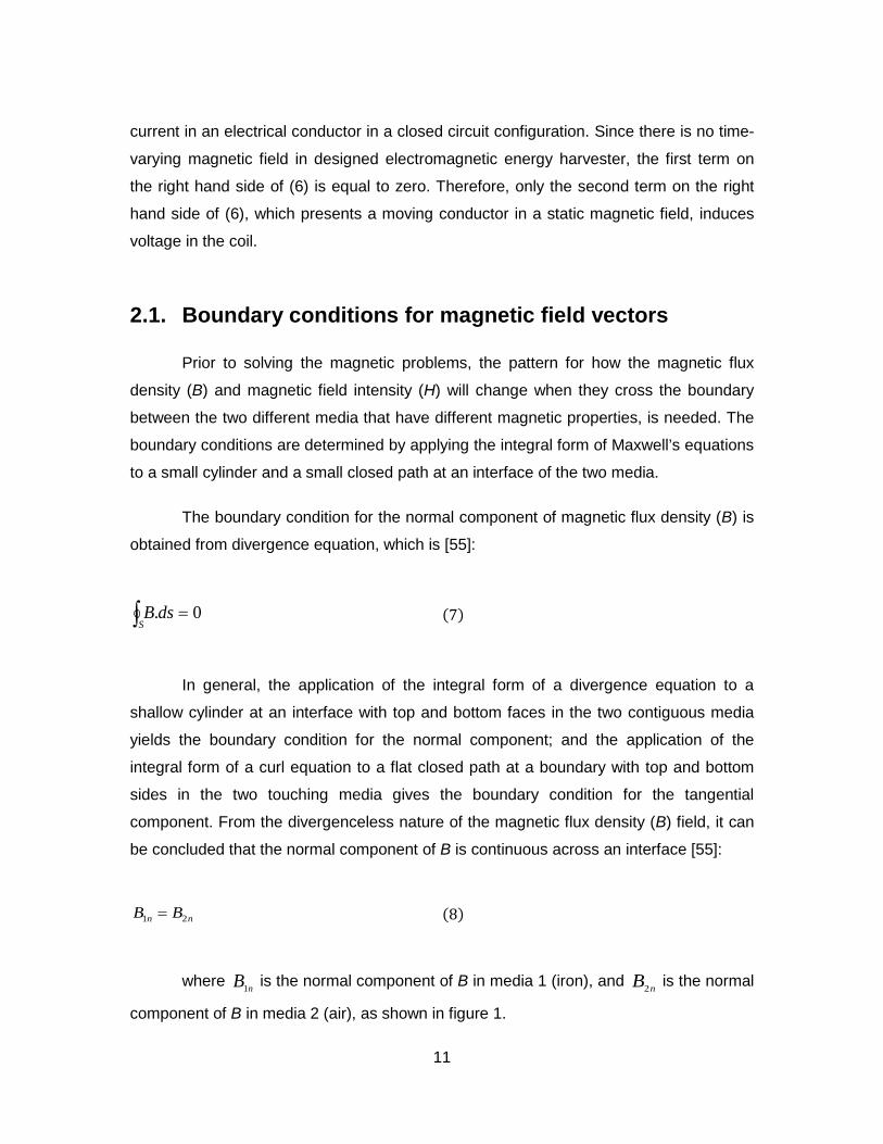
Finally, the reason for the slope at the end of iron cylinder is to avoid the flux
leakages and magnetic losses, and therefore increase the strength of magnetic field on
top of the structure. Moreover, when the iron cylinder has slope at its end, the flux lines
will emerge into air in a direction almost normal ( 90≈ ) to the interface on top of the
electromagnetic energy harvester structure (figure 7-a). But when the iron cylinder does
not have this slope, the flux lines will emerge into air in a direction less than normal (
90< ) to the interface on top of the structure (figure 7-b). Since the induced voltage is
proportional to the Sine of the angle between velocity (u) and magnetic flux density (B),
where velocity (u) is in z-axis direction, therefore decrement in emerge angle of flux lines
into air will cause the value of the Sine decreases a little, which will result in smaller
induced voltage, as will be verified later with experimental analysis.
To conclude the above discussion, it has been illustrated that creating slope at
the end of iron cylinder, plus having a straight iron core with conical end will result in
Magnet
Magnet
CylinderIron
CylinderIron
EdgesshapeTooth
withCoreIron−
CoreIronStraight
27
stronger magnetic field inside the electromagnetic energy harvester structure compare to
other geometric designs.
(a) (b)
Figure 7. The effect of slope at the end of iron cylinder on magnetic losses
A finite element analysis (FEA) has been conducted to better realize the flux
linkage with the coil, demonstrate the magnetic flux density pattern, and estimate the
induced current in the coil. The analysis of the energy harvester structure is done using
COMSOL Multiphysics software.
In the simulation process, the magnetization has been chosen to be in z-direction
since the magnet is axially magnetized. To calculate the magnetization, the B-H curve of
the magnet is used in the fallowing relationship [58]:
(36)
where B is the magnetic field density and H is the magnetic field intensity.
HBM
−=0
1µ
MagnetMagnet
EnditsatSlopewithout
CylinderIron
EnditsatSlopewithCylinderIron
CoreIronCoreIron

28
Based on the dimensions of the magnet, the Permeance Coefficient can be
extracted from the table which relates the Permeance coefficient of a magnetic media to
its dimensions. Therefore, the Permeance coefficient for the used magnet in our setup is
2.211. Therefore, from B-H curve of the magnet and with this Permeance Coefficient, the
magnetic field density (B) is equal to 13000 Gauss or 1.3 [T] and the magnetic field
intensity (H) is equal to -6000 [Oe] or -477 [kA/m]. Hence, the magnetization’s value is
equal to 1.5 [MA/m].
Figure 8. The B-H curve for permanent magnet [59]
In the first step, figure (9) demonstrates the magnetic flux density streamline in
the cross sectional area of the energy harvester in 2D axial symmetry cylindrical
coordinate. The red lines in this figure indicate the magnetic flux density streamline. Now
we have examined that whether the demonstrated pattern for magnetic flux density in
simulation analysis matches the theory principles or not. If two magnetic media with
permeabilities 1µ and 2µ have a common boundary, and the magnetic flux density in
medium 1 and 2 makes an angle 1α and 2α with the normal vectors on the planes
where magnetic medias are in them , respectively, then [55]:
(37)
(37) illustrates that if medium 1 is ferromagnetic (like iron) and medium 2 is air,
which means 21 µµ >> , then 2α will be nearly zero. In other words, if a magnetic field
1
2
1
2
tantan
µµ
αα
=

29
originates in a ferromagnetic medium, similar to this energy harvester, the flux lines will
emerge into air in a direction almost normal to the interface, as is shown in figure (9).
Therefore, the pattern for magnetic field, which is demonstrated by simulation, exactly
matches the theory and with the aim of theory and simulation, it is demonstrated that the
magnetic flux density streamline inside the setup (between iron core and iron cylinder) is
radial.
Figure 9. Magnetic flux density streamline for primary design of electromagnetic energy harvester when iron core has conical end, has tooth-shape edges on it, and iron cylinder has slope at its end
3.2. Analyzing the sinusoidal base excitation vibration through shaker setup
3.2.1. Simulation analysis of sinusoidal base excitation vibration
The First question that needs to be answered is that where would be the ideal
initial position for the coil to produce maximum induced voltage. Therefore, it has been
CylinderIron
MagnetCoreIron

30
examined that how the initial position of the coil will affect on the induced voltage value.
To do so, the excitation of the coil is defined as:
Z = 0.5 sin (70.π.t) mm (38)
To conduct the simulation analysis through Comsol Multiphysics, two main steps
should be done. First, the excitation equation should be defined through moving
meshes, which indicates the pattern for the movement of each part of the setup. Second,
the material properties for each part of the setup, such as magnet, iron cylinder, coil, and
air gap, in addition to their boundary conditions, which has been discussed earlier,
should be identified to be able to plot diverse electromagnetic variables.
During the simulation analysis, the coil has been placed inside the setup
completely and then it has been moved toward the top of the setup slowly. 18 different
initial positions for the coil have been tested and each time, the induced current in the
coil has been recorded. Considering the fact that the resistance of the coil is equal to
20.4 [Ω], with the help of Ohm’s law, which is:
V = R.I (39)
where V is the induced voltage, I is the induced current, and R is the resistance
of the coil, the induced voltage within these initial positions has been calculated and the
result is demonstrated in figure (10).

31
Figure 10. Induced voltage vs. Initial position of the coil: simulation result
Figure (10) indicates that around 13 [mm] on top of the conical end of the
structure, where exactly the first tooth-shape edge locates, the maximum voltage would
induce on coil.
3.2.2. Experimental analysis of sinusoidal base excitation vibration
The energy harvester structure comprises of one outer metal cylinder with the
outer radius of 2 [cm], inner radius of 1.25 [cm], and the height of 7 [cm]; one inner metal
cylinder with the radius of 0.25 [cm] and the height of 8.3 [cm], and it has the cone shape
at one end. Moreover, this iron core has 8 steps on it, where each step has 0.6 [cm]
height and 0.25 [cm] width. One fixed Neodymium ring magnet with the outer radius of
1.9 [cm], inner radius of 0.95 [cm], and the height of 1.9 [cm]. The coil’s shape is also
cylindrical with the outer radius of 8 [mm], inner radius of 4 [mm], and the height of 33
[mm]. Other than the explained energy harvester structure, the experimental setup
comprises of an electromagnetic shaker, miniature accelerometer, and a dynamic signal
analyser. Figure 11 demonstrates the complete experimental setup.
32
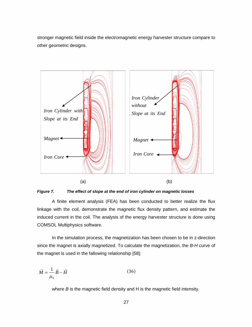
Figure 11. The shaker experimental setup
The same procedure with similar 18 different initial positions as simulation
process and same sinusoidal vibration has been applied on the experimental setup and
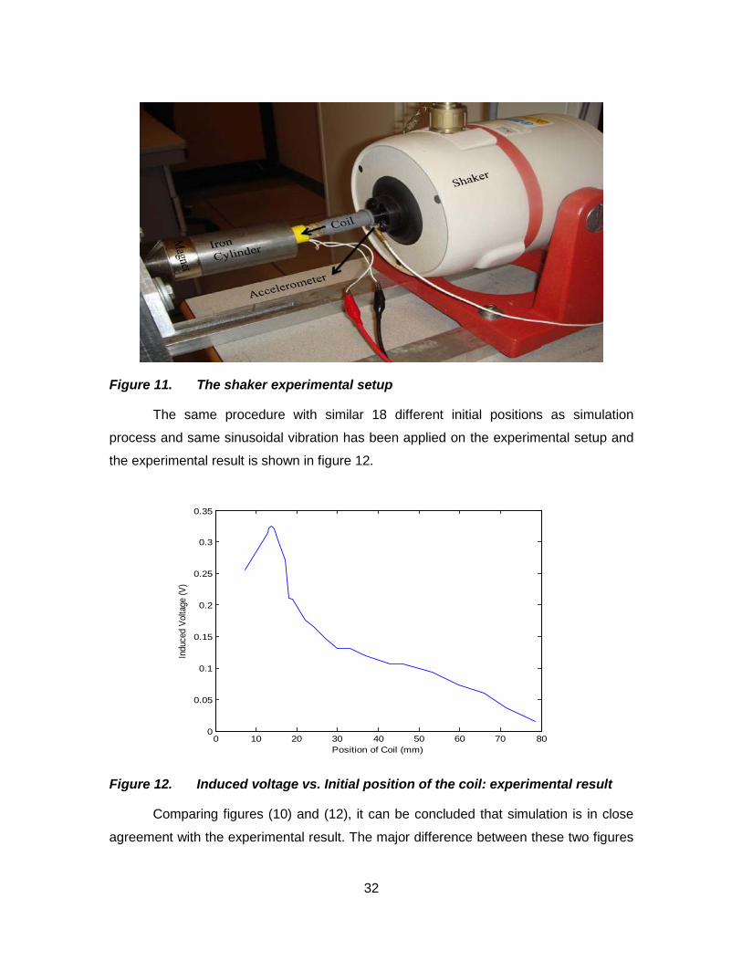
the experimental result is shown in figure 12.
Figure 12. Induced voltage vs. Initial position of the coil: experimental result
Comparing figures (10) and (12), it can be concluded that simulation is in close
agreement with the experimental result. The major difference between these two figures
0 10 20 30 40 50 60 70 800
0.05
0.1
0.15
0.2
0.25
0.3
0.35
Position of Coil (mm)
Indu
ced
Volta
ge (V
)

33
is the peak of induced voltage. The main reasons for this difference are: 1) the flux
linkage leakage happens in reality and cannot be captured in the ideal simulation
environment, 2) the size of the model navigator that has been selected in the simulation,
3) the property of the iron core and the iron cylinder that is used in the simulation. This
also indicates that the losses in reality are more than ideal simulation environment.
Moreover, both figures (10) and (12) illustrate that the ideal initial position, where the
maximum amount of induced voltage would be captured, is around 13.5 [mm] on top of
the cone part of the structure.
3.2.3. Analyzing the effect of design modifications for energy harvester setup through simulation
In subsections 3.2.1. and 3.2.2., it has been demonstrated that the simulation
analysis is in close agreement with the experimental result. Therefore, in this subsection,
numerous FEA’s through COMSOL Multiphysics software have been conducted to
demonstrate the design modifications improvements in quantitative manner. The same
simulation procedure, as mentioned in subsection 3.2.1., has been conducted here
again when only one design parameter has been changed. The following figure
illustrates the effect of changing 3 different design parameters on induced voltage of the
moving coil.

34
Figure 13. Simulation analysis of three different design parameters
Based on figure (13) and considering figure (10) as the demonstration of induced
voltage for original design setup, the improvement percentage of induced voltage in
each case can be calculated by definition below:
(40)
where ChV is the induced voltage obtained when one design parameter has been
changed (demonstrated in figure (13)), and OrV is the induced voltage for original design
setup (demonstrated in figure (10)). Based on equation (40), when the slope at the end
of iron cylinder has been added, the improvement percentage factor equals:
(41)
5 10 15 20 25 30 35 40 45 50 55 600.05
0.1
0.15
0.2
0.25
0.3
0.35
0.4
0.45
0.5
Position of Coil (mm)
Indu
ced
Vol
tage
(V)
Simulation Analysis of Diverse Design Parameters
Iron Cylinder without slope at its endStraight Iron CoreCylindrical shape at the bottom of structure
100)(Im% ×−
=Or
OrChV
VVFactorPercentageprovement α
%417.14100326.0
326.0373.0=×
−=α

35
This positive α indicates that adding the slope at the end of iron cylinder has
increased the induced voltage. Therefore, creating the slope at the end of iron cylinder
improves the induced voltage by %14.417.
In the next case, when the tooth-shape edges have been removed from the iron
core, the improvement percentage factor equals:
(42)
This positive α indicates that removing the tooth-shape edges from iron core, and
therefore having a straight iron core, increased the induced voltage by %25.469.
Finally, when the bottom of energy harvester structure has a conical shape rather
than the cylindrical shape, the improvement percentage factor equals:
(43)
Again, this positive α indicates that changing the bottom shape of energy
harvester structure from cylindrical to conical has increased the induced voltage.
Therefore, the conical shape at the bottom of energy harvester structure improves the
induced voltage by %14.417.
3.3. Experimental analysis of linear motion electromagnetic energy harvester with diverse velocities through linear motor setup
3.3.1. Describing the experimental setup for linear motion
The energy harvester has the same structure as described in subsection 3.2.2,
but only this time, it has been mounted on a linear motor instead of shaker. A schematic
configuration of the experimental setup has been demonstrated in following figure.
%417.14100326.0
326.0373.0=×
−=α
%469.25100373.0
373.0468.0+=×
−=α

36
Moving CoilIron Cylinder Magnet
Figure 14. Schematic configuration of the experimental setup for linear motion
In the following subsections, the effects of the length of iron cylinder, the slope at
its end, and the resistance of the moving coil have been examined. Moreover, diverse
load resistors have been tested at each step to calculate the maximum electrical power
extracted from energy harvester. Finally, all of the above mentioned experimental
analyses have been repeated when the iron core is straight and does not have any
tooth-shape edges to verify the simulation analysis conducted previously. Before starting
the experimental analysis, to get a better sense of different lengths of iron cylinder which
is going to be discussed later on in this chapter, figure (15) comparing these lengths to
each other.

37
(a) (b)
(c) (d)
Figure 15. Demonstrating diverse lengths of iron cylinder: (a) Original length; (b) Half length; (c) One fifth length; (d) One sixth length
3.3.2. Parameter study of energy harvester when iron cylinder has its primary length
As mentioned before, the primary length of iron cylinder is 70 [mm]. Since the
length of the permanent magnet is 20 [mm], therefore the distance from bottom to top of
the energy harvester structure is 90 [mm]. First, to examine the coil resistance effect on
induced voltage with respect to diverse velocities, the experiment has been done in
following two cases:
a) When the iron cylinder has the slope at its end and the coil resistance is equal
to 692 [Ω], and;

38
b) When the iron cylinder has the slope at its end and the coil resistance is equal
to 20.4 [Ω]. The following figure represents the results:
(a) (b)
Figure 16. The coil resistance effect on induced voltage with respect to diverse velocities: (a) coil resistance is 692 [Ω]; (b) coil resistance is 20.4 [Ω]
First of all, it can be concluded that higher velocities will result in higher voltages.
Another point which can be interpreted from above figure is that the position of maximum
induced voltage is dependent on the velocity of coil’s movement slightly. The above
figure illustrates that when the velocity of coil’s movement varies from 17.5 [mm/s] to 70
[mm/s], then the position of induced voltage’s peak changes slightly from 15 [mm] to 20
[mm].
This figure also demonstrates that the relationship between velocity and induced
voltage is almost linear, since when the velocity is doubled (from 35 [mm/s] to 70
[mm/s]), then the induced voltage is almost doubled too (from 0.57 [V] to 1.1 [V] in figure
16-a). Moreover, From this figure, it can be seen that when the velocity has been
increased, on the other hand, the bandwidth of the maximum induced voltage has been
decreased. Comparing two induced voltages when the velocities are 17.5 [mm/s] and 70
[mm/s], although the peak is much higher in case of 70 [mm/s], but the region in which
this peak exists is too narrow. On the other hand, in case of 17.5 [mm/s], although the
value of voltage’s peak is low, but the region in which this peak exists is quite wide.
0 20 40 60 80 100 120-0.2
0
0.2
0.4
0.6
0.8
1
1.2
Displacement [mm]
Indu
ced
Vol
tage
[V
]
Original Length, Coil Resistance: 692 Ohm
Velocity: 17.5 [mm/s]Velocity: 35 [mm/s]Velocity: 52.5 [mm/s]Velocity: 70 [mm/s]
0 20 40 60 80 100 120-0.05
0
0.05
0.1
0.15
0.2
Displacement [mm]In
duced V
oltage [
V]
Original Length, Coil Resistance: 20.4 Ohm
Velocity: 17.5 [mm/s]Velocity: 35 [mm/s]Velocity: 52.5 [mm/s]Velocity: 70 [mm/s]

39
Therefore, in case of lower velocities, it is possible to cover more distances while still
producing the maximum voltage which can be reached.
Finally, it can be seen that when the coil resistance is higher, the induced voltage
in the coil is significantly higher with respect to coils with lower resistance. But does this
higher voltage result in higher harvested power? The next experiment will help to
address this question. Note that since the effect of different velocities has been
examined in this case, later on the experimental tests has been conducted only when
the velocity of moving coil is 70 [mm/s].
Therefore, the next step of experimental analysis has been conducted to
examine the coil resistance effect on harvested power with respect to diverse load
resistors. This step has been done again for both cases when the coil resistance is 692
[Ω] and the other one when the coil resistance is 20.4 [Ω]. The results are demonstrated
below:
(a) (b)
Figure 17. The coil resistance effect on harvested power with respect to diverse load resistors: (a) coil resistance is 692 [Ω]; (b) coil resistance is 20.4 [Ω]
Based on the impedance matching, the maximum power occurs when the load
resistor is equal to the coil resistance. In the case when coil resistance is 692 [Ω], based
on the power equation (R
VP2
= ), the maximum power is equal to:
0 20 40 60 80 100 120-0.2
0
0.2
0.4
0.6
0.8
1
1.2
Displacement [mm]
Induced V
oltage [
V]
Original Length, Coil Resistance: 692 Ohm
Load Resistor: 100 [Ohm]Load Resistor: 680 [Ohm]Load Resistor: 1.8 [KOhm]Load Resistor: 10 [KOhm]
0 20 40 60 80 100 120-0.05
0
0.05
0.1
0.15
0.2
Displacement [mm]
Indu
ced
Vol
tage
[V
]
Original Length, Coil Resistance: 20.4 Ohm
Load Resistor: 10 [Ohm]Load Resistor: 20 [Ohm]Load Resistor: 50 [Ohm]Load Resistor: 10 [KOhm]

40
].[421.0680
)535.0( 2
maxmWP == The voltage’s peaks in figure (17) determine the
maximum electrical power which is extracted from energy harvester based on various
load resistors that have been tested. Figure (19) compares these powers which have
been calculated experimentally to the power versus load resistor graph which has been
obtained numerically. To obtain the numerical equation, the whole energy harvester
setup has been considered as a voltage source with internal resistor equal to coil
resistance. This voltage source is able to produce the maximum voltage S
V which is
equal to voltage’s peak at speed of 70 [mm/s] when there is no load resistor. The
equivalent circuit is illustrated below:
Figure 18. The equivalent electrical circuit for energy harvester setup with variable load resistors
To obtain the numerical graph, the following two equations have been used
simultaneously:
(44)
The result is demonstrated in figure (19).
Voltage Source(Vs)
Variable Load Resistor(RL)
R +-
Internal Resistor(Rs)
+ -
=
+=
L
LL
SLS
LL
RVP
VRR
RV
2

41
Figure 19. Comparison between numerical analysis and experimental result for load powers with respect to variable load resistors
At last, based on the impedance matching again, the maximum power in the
case when coil resistance is 20.4 [Ω], is equal to:
].[3321.020
)0815.0( 2
max mWP ==
Comparing the maximum harvested power in both cases, it can be concluded
that although when the induced voltage (or coil resistance) is higher, the harvested
power is slightly higher too, but this significantly higher voltage has not resulted in
significantly higher power, as the difference in harvested powers between these two
cases is less than 0.1 [mW]. Again note that since the effect of different load resistors
has been demonstrated in this case, later on the experimental tests has been conducted
only with the optimum load resistor which can harvest the maximum power from linear
motion.
3.3.3. Parameter study of energy harvester when iron cylinder has half of its primary length
As mentioned before, since the primary length of iron cylinder is 70 [mm],
therefore half of its length is 35 [mm]. In this section, all the experiments which have
been done in previous section are going to be performed one more time. Additionally,
0 1000 2000 3000 4000 5000 6000 7000 8000 9000 100000
0.05
0.1
0.15
0.2
0.25
0.3
0.35
0.4
0.45
Load Resistor(ohm)
Load
Pow
er (m
W)
Original Length, Coil Resistance: 692 (ohm)
Experimental ResultNumerical Result

42
the effect of slope at the end of iron cylinder on induced voltage with respect to diverse
velocities has been examined in this section. To analyze the slope effect, and to keep
only one variable parameter in experimental procedure, for only this part it has been
chosen to conduct the experiment on the coil with 692 [Ω] internal resistance. The
following figure demonstrates the effect of slope at the end of iron cylinder on induced
voltage:
Figure 20. Effect of slope at the end of iron cylinder on induced voltage when iron cylinder has the half of its primary length
This figure illustrates that creating a slope at the end of iron cylinder will improve
the amount of induced voltage about 0.2 [V]. Moreover, these two graphs can be used to
verify the simulation analysis on improvement percentage factor, which has been
conducted in subsection 3.2.3, with experimental results. Since the only parameter
which has been changed in this part is the slope at the end of iron cylinder, therefore the
improvement percentage factor equals:
(45)
which is in close agreement with simulation analysis when the slope at the end of
iron cylinder has been added (%14.417).
0 20 40 60 80 100 120-1
-0.5
0
0.5
1
1.5
2
Displacement [mm]
Indu
ced
Vol
tage
[V]
Slope Effect for Half of Original Length, Coil Resistance: 692 Ohm
With SlopeWithout Slope
%5.121006.1
6.18.1=×
−=α

43
Now to conduct the experiments which have been done in previous section, first
the effect of coil resistance on induced voltage with respect to diverse velocities has
been demonstrated.
Since in the previous experiment, it has been concluded that the slope at the end
of iron cylinder will cause higher induced voltage, Therefore this part of experiment has
been done when the iron cylinder has the slope at its end. Again, the experimental
results for both coils are as follows:
Figure 21. The coil resistance effect on induced voltage when iron cylinder has half of its primary length
When the coil resistance is 20.4 [Ω], the maximum induced voltage which has
been reached when the iron cylinder has the half length of its primary length is 0.3 [V],
while in similar case when the iron cylinder has its primary length, this maximum induced
voltage was around 0.17 [V]. These measurements indicate that when the iron cylinder
has been cut to its half length, the induced voltage has increased by the factor 1.76.
Similarly, when the coil resistance is 692 [Ω], the maximum induced voltage which has
been reached when the iron cylinder has the half length of its primary length is 1.85 [V],
while in similar case when the iron cylinder has its primary length, this maximum induced
voltage was around 1.1 [V]. Again, these measurements indicate that when the iron
0 20 40 60 80 100 120-1
-0.5
0
0.5
1
1.5
2
Displacement [mm]
Indu
ced
Vol
tage
[V]
Coil Resistance Effect on Induced Voltage for Half of Original Length
Coil Resistance is 692 [Ohm]Coil Resistance is 20.4 [Ohm]

44
cylinder has been cut to its half length, the induced voltage has increased by the factor
1.68, which is in close agreement when the coil resistance is 20.4 [Ω].
What can be discussed more on figure (21)? Perhaps the most interesting
phenomenon which has been illustrated in this figure is that there are two voltage peaks;
one is positive, and the other one is negative. This means that there is a point in the
structure where the induced voltage in the moving coil equals zero. The position of this
point among the structure depends on the length of the iron cylinder. In fact, the length
of iron cylinder is equal to the position of the point where the induced voltage is zero.
This phenomenon is interesting because the magnetic flux density (B) becomes zero
with the use of only one permanent magnet and the special design and configuration of
the energy harvester setup. To interpret this phenomenon, from induced voltage
formulation, since the length of the moving coil is always constant and the velocity of
coil’s movement is set to a constant value before each experiment, therefore the
magnetic flux density (B) is the only parameter which is variable. Hence, at this position,
the magnetic flux density (B) should be zero. The next step is to answer how the
magnetic flux density (B) becomes zero at this point? Since the magnetic flux density (B)
is a vector, therefore it becomes zero either when its magnitude becomes zero or when
the total resultant of this vector in different directions at that point is zero. In this
configuration, the latter case is true since at the end of iron cylinder, some of the
magnetic field lines close themselves through the iron core, but the rest of them, which
are the magnetic losses, are closing themselves in opposite direction through air. Thus,
these two opposite magnetic flux densities cancel out each other and the resultant
magnetic flux density (B) at the end of iron cylinder becomes zero.
Finally, the effect of coil resistance on harvested power with respect to diverse
load resistors for both coils has been determined in following figure:

45
(a) (b)
Figure 22. The coil resistance effect on harvested power when iron cylinder has half of its primary length: (a) coil resistance is 692 [Ω]; (b) coil resistance is 20.4 [Ω]
Based on the impedance matching, the maximum power occurs when the load
resistor is equal to the coil resistance. In the case when coil resistance is 692 [Ω], based
on the power equation (R
VP2
= ), the maximum power is equal to:
].[191.1680
)900.0( 2
maxmWP ==
Again, figure (23) compares both powers which have been calculated
experimentally and the power versus load resistor graph which has been obtained
numerically for this case.
0 20 40 60 80 100 120-0.4
-0.2
0
0.2
0.4
0.6
0.8
1
Displacement [mm]
Induced V
oltage [
V]
Half of Original Length, Coil Resistance: 692 [Ohm], Load Resistance: 680 [Ohm]
0 20 40 60 80 100 120-0.1
-0.05
0
0.05
0.1
0.15
Displacement [mm]
Induced V
oltage [
V]
Half of Original Length, Coil Resistance: 20.4 [Ohm], Load Resistance: 20 [Ohm]

46
Figure 23. Comparison between numerical analysis and experimental result for load powers with respect to variable load resistors when iron cylinder has half of its primary length
At last, based on the impedance matching again, the maximum power in the
case when coil resistance is 20.4 [Ω] is equal to:
].[066.120
)146.0( 2
max mWP ==
Comparing these results to the case when the iron cylinder had its primary
length, it can be shown that when the coil resistance is 692 [Ω], the maximum harvested
power has increased by the factor 2.829, which is equal to square of the factor that
induced voltage has been increased ( )268.1 , while when the coil resistance is 20.4 [Ω],
the maximum harvested power has increased by the factor 3.21, which is almost equal
to square of the factor that induced voltage has been increased ( )276.1 .
3.3.4. Parameter study of energy harvester when iron cylinder has one third of its primary length
As discussed earlier, since the primary length of iron cylinder is 70 [mm],
therefore one third of its length is 23.33 [mm]. In this section, all the experimental steps
which have been done in previous section (3.3.3) are going to be repeated here again.
0 1000 2000 3000 4000 5000 6000 7000 8000 9000 100000
0.2
0.4
0.6
0.8
1
1.2
1.4
Load Resistor(ohm)
Load
Pow
er (m
W)
Half of Original Length, Coil Resistance: 692 (ohm)
Experimental ResultNumerical Result

47
The following figure illustrates the effect of slope at the end of iron cylinder on induced
voltage when the coil resistance is 692 [Ω]:
Figure 24. Effect of slope at the end of iron cylinder on induced voltage when iron cylinder has the one third of its primary length
This time, based on figure above, creating a slope at the end of iron cylinder will
improve the amount of induced voltage about 0.1 [V].
Second, the effect of coil resistance on induced voltage with respect to diverse
velocities has been demonstrated below for both coils:
0 20 40 60 80 100 120-1
-0.5
0
0.5
1
1.5
2
2.5
Displacement [mm]
Indu
ced
Vol
tage
[V]
Slope Effect for One Third of Original Length, Coil Resistance: 692 Ohm
With SlopeWithout Slope

48
Figure 25. The coil resistance effect on induced voltage when iron cylinder has one third of its primary length
When the coil resistance is 20.4 [Ω], the maximum induced voltage which has
been reached when the iron cylinder has the one third length of its primary length is 0.39
[V], while in similar case when the iron cylinder has its primary length, this maximum
induced voltage was around 0.17 [V]. These measurements indicate that when the iron
cylinder has been cut to its one third length, the induced voltage has increased by the
factor 2.3. Similarly, when the coil resistance is 692 [Ω], the maximum induced voltage
which has been reached when the iron cylinder has the one third length of its primary
length is 2.3 [V], while in similar case when the iron cylinder has its primary length, this
maximum induced voltage was around 1.1 [V]. Again, these measurements indicate that
when the iron cylinder has been cut to its one third length, the induced voltage has
increased by the factor 2.1, which is in close agreement when the coil resistance is 20.4
[Ω].
Third, the effect of coil resistance on harvested power with respect to diverse
load resistors for both coils has been determined in following figure:
0 20 40 60 80 100 120-1
-0.5
0
0.5
1
1.5
2
2.5
Displacement [mm]
Indu
ced
Vol
tage
[V]
Coil Resistance Effect on Induced Voltage for One Third of Original Length
Coil Resistance is 692 [Ohm]Coil Resistance is 20.4 [Ohm]

49
(a) (b)
Figure 26. The coil resistance effect on harvested power when iron cylinder has one third of its primary length: (a) coil resistance is 692 [Ω]; (b) coil resistance is 20.4 [Ω].
Based on the impedance matching and the power equation, the maximum power
when coil resistance equals 692 [Ω] is equal to: ].[684.1680
)070.1( 2
maxmWP ==
Again, figure (27) compares both powers which have been calculated
experimentally and the power versus load resistor graph which has been obtained
numerically when the coil resistance is 692 [Ω].
0 20 40 60 80 100 120-0.4
-0.2
0
0.2
0.4
0.6
0.8
1
1.2
Displacement [mm]
Indu
ced
Vol
tage
[V
]
One Third of Original Length, Coil Resistance: 692 [Ohm], Load Resistance: 680 [Ohm]
0 20 40 60 80 100 120-0.1
-0.05
0
0.05
0.1
0.15
0.2
0.25
Displacement [mm]
Induced V
oltage [
V]
One Third of Original Length, Coil Resistance: 20.4 [Ohm], Load Resistance: 20 [Ohm]

50
Figure 27. Comparison between numerical analysis and experimental result for load powers with respect to variable load resistors when iron cylinder has one third of its primary length
Finally, based on the impedance matching again, the maximum power in the
case when coil resistance is 20.4 [Ω] is equal to:
].[711.120
)185.0( 2
max mWP ==
Comparing these results to the case when the iron cylinder had its primary
length, it can be shown that when the coil resistance is 692 [Ω], the maximum harvested
power has increased by the factor 4, which is almost equal to square of the factor that
induced voltage has been increased ( )21.2 , while when the coil resistance is 20.4 [Ω],
the maximum harvested power has increased by the factor 5.15, which is almost equal
to square of the factor that induced voltage has been increased ( )23.2 .
3.3.5. Parameter study of energy harvester when iron cylinder has quarter of its primary length
Same as previous sections, since the primary length of iron cylinder is 70 [mm],
therefore quarter of its length is 17.5 [mm]. In this section, all the experimental steps
which have been done in previous sections are going to be repeated here again. The
0 1000 2000 3000 4000 5000 6000 7000 8000 9000 100000
0.2
0.4
0.6
0.8
1
1.2
1.4
1.6
1.8
2
Load Resistor(ohm)
Load
Pow
er (m
W)
One Third Length, Coil Resistance: 692 (ohm)
Experimental ResultNumerical Result
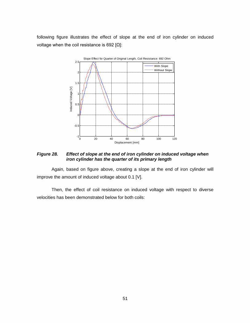
51
following figure illustrates the effect of slope at the end of iron cylinder on induced
voltage when the coil resistance is 692 [Ω]:
Figure 28. Effect of slope at the end of iron cylinder on induced voltage when iron cylinder has the quarter of its primary length
Again, based on figure above, creating a slope at the end of iron cylinder will
improve the amount of induced voltage about 0.1 [V].
Then, the effect of coil resistance on induced voltage with respect to diverse
velocities has been demonstrated below for both coils:
0 20 40 60 80 100 120-1
-0.5
0
0.5
1
1.5
2
2.5
Displacement [mm]
Indu
ced
Vol
tage
[V]
Slope Effect for Quarter of Original Length, Coil Resistance: 692 Ohm
With SlopeWithout Slope

52
Figure 29. The coil resistance effect on induced voltage when iron cylinder has quarter of its primary length
When the coil resistance is 20.4 [Ω], the maximum induced voltage which has
been reached when the iron cylinder has the quarter length of its primary length is 0.4
[V], while in similar case when the iron cylinder has its primary length, this maximum
induced voltage was around 0.17 [V]. These measurements indicate that when the iron
cylinder has been cut to its quarter length, the induced voltage has increased by the
factor 2.35. Similarly, when the coil resistance is 692 [Ω], the maximum induced voltage
which has been reached when the iron cylinder has the quarter length of its primary
length is 2.45 [V], while in similar case when the iron cylinder has its primary length, this
maximum induced voltage was around 1.1 [V]. Again, these measurements indicate that
when the iron cylinder has been cut to its quarter length, the induced voltage has
increased by the factor 2.23, which is in close agreement when the coil resistance is
20.4 [Ω].
Lastly, the effect of coil resistance on harvested power with respect to diverse
load resistors for both coils has been determined in following figure:
0 20 40 60 80 100 120-1
-0.5
0
0.5
1
1.5
2
2.5
Displacement [mm]
Indu
ced
Vol
tage
[V]
Coil Resistance Effect on Induced Voltage for Quarter of Original Length
Coil Resistance is 692 [Ohm]Coil Resistance is 20.4 [Ohm]

53
(a) (b)
Figure 30. The coil resistance effect on harvested power when iron cylinder has quarter of its primary length: (a) coil resistance is 692 [Ω]; (b) coil resistance is 20.4 [Ω]
Again, based on the impedance matching, and the power equation, when the coil
resistance is 692 [Ω], the maximum power is equal to:
].[828.1680
)115.1( 2
maxmWP ==
One more time, figure (31) compares both powers which have been calculated
experimentally and the power versus load resistor graph which has been obtained
numerically.
0 20 40 60 80 100 120-0.4
-0.2
0
0.2
0.4
0.6
0.8
1
1.2
Displacement [mm]
Indu
ced
Vol
tage
[V
]
Quarter of Original Length, Coil Resistance: 692 [Ohm], Load Resistance: 680 [Ohm]
0 20 40 60 80 100 120-0.1
-0.05
0
0.05
0.1
0.15
0.2
0.25
Displacement [mm]
Indu
ced
Vol
tage
[V
]
Quarter of Original Length, Coil Resistance: 20.4 [Ohm], Load Resistance: 20 [Ohm]

54
Figure 31. Comparison between numerical analysis and experimental result for load powers with respect to variable load resistors when iron cylinder has quarter of its primary length
Finally, based on the impedance matching, the maximum power in the case
when coil resistance is 20.4 [Ω] is equal to:
].[656.120
)182.0( 2
max mWP ==
Comparing these results to the case when the iron cylinder had its primary
length, it can be concluded that when the coil resistance is 692 [Ω], the maximum
harvested power has increased by the factor 4.342, which is almost equal to square of
the factor that induced voltage has been increased ( )223.2 , while when the coil
resistance is 20.4 [Ω], the maximum harvested power has increased by the factor 4.988,
which is almost equal to square of the factor that induced voltage has been increased
( )235.2 .
3.3.6. Parameter study of energy harvester when iron cylinder has one fifth of its primary length
Same as before, since the primary length of iron cylinder is 70 [mm], therefore
one fifth of its length is 14 [mm]. In this section, again all the experimental steps which
have been done in previous sections are going to be repeated. The following figure
0 1000 2000 3000 4000 5000 6000 7000 8000 9000 100000
0.5
1
1.5
2
2.5
Load Resistor(ohm)
Load
Pow
er (m
W)
Quarter Length, Coil Resistance: 692 (ohm)
Experimental ResultNumerical Result

55
illustrates the effect of slope at the end of iron cylinder on induced voltage when the coil
resistance is 692 [Ω]:
Figure 32. Effect of slope at the end of iron cylinder on induced voltage when iron cylinder has the one fifth of its primary length
Again, based on figure above, creating a slope at the end of iron cylinder will
improve the amount of induced voltage about 0.1 [V].
Another interesting phenomenon which can be pointed out is the negative
voltage’s peak. This peak indicates that even when the direction of magnetic field is
changed due to the design configuration, there is still another point on this area with
opposite direction of magnetic field which has the strongest magnetic field intensity
relative to its neighboring points. Although the intensity of this magnetic field is relatively
low since this point is almost too far from the magnetic source.
In next step, the effect of coil resistance on induced voltage with respect to
diverse velocities has been demonstrated below for both coils:
0 20 40 60 80 100 120-1
-0.5
0
0.5
1
1.5
2
2.5
Displacement [mm]
Indu
ced
Vol
tage
[V]
Slope Effect for One Fifth of Original Length, Coil Resistance: 692 Ohm
With SlopeWithout Slope

56
Figure 33. The coil resistance effect on induced voltage when iron cylinder has one fifth of its primary length
When the coil resistance is 20.4 [Ω], the maximum induced voltage which has
been reached when the iron cylinder has the one fifth length of its primary length is 0.42
[V], while in similar case when the iron cylinder has its primary length, this maximum
induced voltage was around 0.17 [V]. These measurements indicate that when the iron
cylinder has been cut to its one fifth length, the induced voltage has increased by the
factor 2.47. Similarly, when the coil resistance is 692 [Ω], the maximum induced voltage
which has been reached when the iron cylinder has the one fifth length of its primary
length is 2.45 [V], while in similar case when the iron cylinder has its primary length, this
maximum induced voltage was around 1.1 [V]. Again, these measurements indicate that
when the iron cylinder has been cut to its one fifth length, the induced voltage has
increased by the factor 2.23, which is in close agreement when the coil resistance is
20.4 [Ω].
In last step, the effect of coil resistance on harvested power with respect to
diverse load resistors for both coils has been determined in following figure:
0 20 40 60 80 100 120-1
-0.5
0
0.5
1
1.5
2
2.5
Displacement [mm]
Indu
ced
Vol
tage
[V]
Coil Resistance Effect on Induced Voltage for One Fifth of Original Length
Coil Resistance is 692 [Ohm]Coil Resistance is 20.4 [Ohm]

57
(a) (b)
Figure 34. The coil resistance effect on harvested power when iron cylinder has one fifth of its primary length: (a) coil resistance is 692 [Ω]; (b) coil resistance is 20.4 [Ω]
As the same procedure as previous sections, the maximum power when the coil
resistance is 692 [Ω] is equal to: ].[845.1680
)120.1( 2
maxmWP ==
Same as before, the following figure compares both powers which have been
calculated experimentally and the power versus load resistor graph which has been
obtained numerically.
0 20 40 60 80 100 120-0.4
-0.2
0
0.2
0.4
0.6
0.8
1
1.2
Displacement [mm]
Indu
ced
Vol
tage
[V
]
One Fifth of Original Length, Coil Resistance: 692 [Ohm], Load Resistance: 680 [Ohm]
0 20 40 60 80 100 120-0.1
-0.05
0
0.05
0.1
0.15
0.2
0.25
Displacement [mm]
Induced V
oltage [
V]
One Fifth of Original Length, Coil Resistance: 20.4 [Ohm], Load Resistance: 20 [Ohm]

58
Figure 35. Comparison between numerical analysis and experimental result for load powers with respect to variable load resistors when iron cylinder has one fifth of its primary length
In other coil (coil resistance is 20.4 [Ω]), the maximum power is equal to:
].[000.220
)200.0( 2
maxmWP ==
Comparing these results to the case when the iron cylinder had its primary
length, it can be concluded that when the coil resistance is 692 [Ω], the maximum
harvested power has increased by the factor 4.382, which is almost equal to square of
the factor that induced voltage has been increased ( )223.2 , while when the coil
resistance is 20.4 [Ω], the maximum harvested power has increased by the factor 6.024,
which is almost equal to square of the factor that induced voltage has been increased
( )247.2 .
3.3.7. Parameter study of energy harvester when iron cylinder has one sixth of its primary length
As the final length to be tested (11.67 [mm]), again all the experimental steps
which have been done in previous sections are going to be repeated. The following
0 1000 2000 3000 4000 5000 6000 7000 8000 9000 100000
0.5
1
1.5
2
2.5
Load Resistor(ohm)
Load
Pow
er (m
W)
One Fifth Length, Coil Resistance: 692 (ohm)
Experimental ResultNumerical Result

59
figure illustrates the effect of slope at the end of iron cylinder on induced voltage when
the coil resistance is 692 [Ω]:
Figure 36. Effect of slope at the end of iron cylinder on induced voltage when iron cylinder has the one sixth of its primary length
Same as before and based on above figure, creating a slope at the end of iron
cylinder will improve the amount of induced voltage about 0.1 [V].
In next level, the effect of coil resistance on induced voltage with respect to
diverse velocities has been demonstrated below for both coils:
0 20 40 60 80 100 120-1
-0.5
0
0.5
1
1.5
2
2.5
3
Displacement [mm]
Indu
ced
Vol
tage
[V]
Slope Effect for One Sixth of Original Length, Coil Resistance: 692 Ohm
With SlopeWithout Slope

60
Figure 37. The coil resistance effect on induced voltage when iron cylinder has one sixth of its primary length
When the coil resistance is 20.4 [Ω], the maximum induced voltage which has
been reached when the iron cylinder has the one sixth length of its primary length is 0.43
[V], while in similar case when the iron cylinder has its primary length, this maximum
induced voltage was around 0.17 [V]. These measurements indicate that when the iron
cylinder has been cut to its one sixth length, the induced voltage has increased by the
factor 2.53. Similarly, when the coil resistance is 692 [Ω], the maximum induced voltage
which has been reached when the iron cylinder has the one sixth length of its primary
length is 2.6 [V], while in similar case when the iron cylinder has its primary length, this
maximum induced voltage was around 1.1 [V]. Again, these measurements indicate that
when the iron cylinder has been cut to its one sixth length, the induced voltage has
increased by the factor 2.36, which is in close agreement when the coil resistance is
20.4 [Ω].
In last part, the effect of coil resistance on harvested power with respect to
diverse load resistors for both coils has been determined in following figure:
0 20 40 60 80 100 120-1
-0.5
0
0.5
1
1.5
2
2.5
3
Displacement [mm]
Indu
ced
Vol
tage
[V]
Coil Resistance Effect on Induced Voltage for One Sixth of Original Length
Coil Resistance is 692 [Ohm]Coil Resistance is 20.4 [Ohm]

61
Figure 38. The coil resistance effect on harvested power when iron cylinder has one sixth of its primary length: (a) coil resistance is 692 [Ω]; (b) coil resistance is 20.4 [Ω]
In the case when coil resistance is 692 [Ω], the maximum power is equal to:
].[391.2680
)275.1( 2
maxmWP ==
Same as previous sections, figure (39) compares both powers which have been
calculated experimentally and the power versus load resistor graph which has been
obtained numerically.
0 20 40 60 80 100 120-0.4
-0.2
0
0.2
0.4
0.6
0.8
1
1.2
1.4
Displacement [mm]
Induced V
oltage [
V]
One sixth of Original Length, Coil Resistance: 692 [Ohm], Load Resistance: 680 [Ohm]
0 20 40 60 80 100 120-0.1
-0.05
0
0.05
0.1
0.15
0.2
0.25
Displacement [mm]
Induced V
oltage [
V]
One Sixth of Original Length, Coil Resistance: 20.4 [Ohm], Load Resistance: 20 [Ohm]

62
Figure 39. Comparison between numerical analysis and experimental result for load powers with respect to variable load resistors when iron cylinder has one sixth of its primary length
Finally when the coil resistance is 20.4 [Ω], the maximum power in this case is
equal to:
].[247.220
)212.0( 2
maxmWP ==
Comparing these results to the case when the iron cylinder had its primary
length, it can be concluded that when the coil resistance is 692 [Ω], the maximum
harvested power has increased by the factor 5.679, which is almost equal to square of
the factor that induced voltage has been increased ( )236.2 , while when the coil
resistance is 20.4 [Ω], the maximum harvested power has increased by the factor 6.768,
which is almost equal to square of the factor that induced voltage has been increased
( )253.2 .
3.3.8. Parameter study of energy harvester when there is no iron cylinder
To complete the discussion about the length effect of iron cylinder on induced
voltage and harvested power, it is needed to test the setup without iron cylinder (the
0 1000 2000 3000 4000 5000 6000 7000 8000 9000 100000
0.5
1
1.5
2
2.5
Load Resistor(ohm)
Load
Pow
er (m
W)
One Sixth Length, Coil Resistance: 692 (ohm)
Experimental ResultNumerical Result

63
length is zero in this case). First of all, the coil resistance effect on induced voltage with
respect to diverse velocities has been examined for both coils:
Figure 40. The coil resistance effect on induced voltage when there is no iron cylinder
When the coil resistance is 20.4 [Ω], the maximum induced voltage which has
been reached when there is no iron cylinder is 0.39 [V], while in similar case when the
iron cylinder has its primary length, this maximum induced voltage was around 0.17 [V].
These measurements indicate that when there is no iron cylinder, the induced voltage
has increased by the factor 2.29. Similarly, when the coil resistance is 692 [Ω], the
maximum induced voltage which has been reached when there is no iron cylinder is 2.35
[V], while in similar case when the iron cylinder has its primary length, this maximum
induced voltage was around 1.1 [V]. Again, these measurements indicate that when
there is no iron cylinder, the induced voltage has increased by the factor 2.14, which is in
close agreement when the coil resistance is 20.4 [Ω].
The final step of experimental analysis in this section has been conducted to
examine the coil resistance effect on harvested power with respect to diverse load
resistors for both coils:
0 20 40 60 80 100 120-1
-0.5
0
0.5
1
1.5
2
2.5
Displacement [mm]
Indu
ced
Vol
tage
[V]
Coil Resistance Effect on Induced Voltage for No Iron Cylinder
Coil Resistance is 692 [Ohm]Coil Resistance is 20.4 [Ohm]

64
Figure 41. The coil resistance effect on harvested power when there is no iron cylinder: (a) coil resistance is 692 [Ω]; (b) coil resistance is 20.4 [Ω]
When coil resistance is 692 [Ω], based on above figure, the maximum power is
equal to: ].[878.1680
)130.1( 2
maxmWP ==
Now, just like every other sections in this chapter, figure (42) compares both
powers which have been calculated experimentally and the power versus load resistor
graph which has been obtained numerically.
0 20 40 60 80 100 120-0.4
-0.2
0
0.2
0.4
0.6
0.8
1
1.2
Displacement [mm]
Induced V
oltage [
V]
No Iron Cylinder, Coil Resistance: 692 [Ohm], Load Resistance: 680 [Ohm]
0 20 40 60 80 100 120-0.1
-0.05
0
0.05
0.1
0.15
0.2
0.25
Displacement [mm]
Induced V
oltage [
V]
No Iron Cylinder, Coil Resistance: 20.4 [Ohm], Load Resistance: 20 [Ohm]

65
Figure 42. Comparison between numerical analysis and experimental result for load powers with respect to variable load resistors when there is no iron cylinder
When the coil resistance is 20.4 [Ω], based on figure (41), the maximum power in
this case is equal to:
].[960.120
)198.0( 2
maxmWP ==
Comparing these results to the case when the iron cylinder had its primary
length, it can be concluded that when the coil resistance is 692 [Ω], the maximum
harvested power has increased by the factor 4.461, which is almost equal to square of
the factor that induced voltage has been increased ( )214.2 , while when the coil
resistance is 20.4 [Ω], the maximum harvested power has increased by the factor 5.904,
which is almost equal to square of the factor that induced voltage has been increased
( )229.2 .
3.3.9. Conclusion
Based on all the steps which have been conducted so far in this chapter, the
following graphs demonstrate the maximum voltage and maximum power versus the
diverse lengths of iron cylinder which have been tested to determine the optimum length
0 1000 2000 3000 4000 5000 6000 7000 8000 9000 100000
0.5
1
1.5
2
2.5
Load Resistor(ohm)
Load
Pow
er (m
W)
No Iron Cylinder, Coil Resistance: 692 (ohm)
Experimental ResultNumerical Result

66
for the energy harvesting setup. (For illustrating the following graphs, the speed of
moving coil is considered to be 70 [mm/s]).

67
(a)
(b)
Figure 43. The induced voltage and harvested power based on diverse lengths of iron cylinder: (a) induced voltage for both coils; (b) harvested power for both coils
0 1 2 3 4 5 6 71
1.5
2
2.5
3
Length (cm)
Max
imum
Indu
ced
Vol
tage (
Vol
t)
Coil Resistance: 692 (ohm)
0 1 2 3 4 5 6 70.1
0.2
0.3
0.4
0.5
Length (cm)
Max
imum
Indu
ced
Vol
tage (
Vol
t)
Coil Resistance: 20.4 (ohm)
0 1 2 3 4 5 6 70
0.5
1
1.5
2
2.5
Length (cm)
M a
x i m
u m
P o
w e r
(
m W
)
Coil Resistance:692 [Ohm]Coil Resistance:20.4 [Ohm]

68
Based on this figure, the optimum length for iron cylinder in respect to inducing
maximum voltage and retrieving maximum power from electromagnetic energy harvester
is about 1.167 [cm]. Moreover, it can be seen that the general behavior of both coils are
in close agreement with each other. Although the coil with higher resistance produces
much more voltage comparing to the coil with lower resistance, but the harvested power
on load resistors for both coils are almost the same as each other and generally the coil
with higher resistance harvests power slightly more than the coil with lower resistance.
3.4. Experimental analysis when the iron core has no tooth-shape edges
As discussed earlier in simulation analysis, when the iron core has no tooth-
shape edges, the magnetic flux density (B) losses outside the energy harvester setup
are low and the density of magnetic fluxes inside iron core is high compare to when the
iron core has the tooth-shape edges. Therefore, the magnetic field in air gap between
iron core and iron cylinder is stronger when the iron core has no tooth-shape edges. This
concept has been tested experimentally for verification in following subsections.
3.4.1. Parameter study of energy harvester when iron cylinder has its primary length (iron core has no tooth-shape edges)
In this subsection, all of the experimental steps which have been conducted in
subsection (3.3.2) have been repeated again to demonstrate the effect of removing
tooth-shape edges from iron core experimentally. First, the coil resistance effect on
induced voltage with respect to diverse velocities has been examined for both coils:
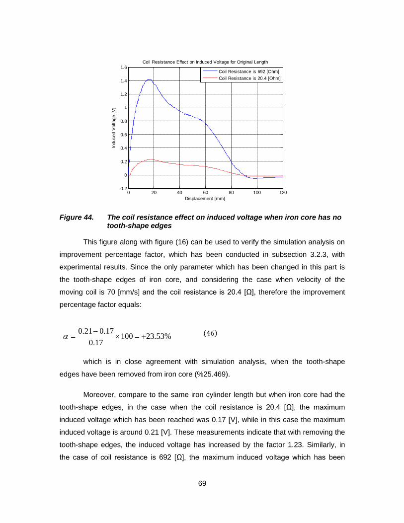
69
Figure 44. The coil resistance effect on induced voltage when iron core has no tooth-shape edges
This figure along with figure (16) can be used to verify the simulation analysis on
improvement percentage factor, which has been conducted in subsection 3.2.3, with
experimental results. Since the only parameter which has been changed in this part is
the tooth-shape edges of iron core, and considering the case when velocity of the
moving coil is 70 [mm/s] and the coil resistance is 20.4 [Ω], therefore the improvement
percentage factor equals:
(46)
which is in close agreement with simulation analysis, when the tooth-shape
edges have been removed from iron core (%25.469).
Moreover, compare to the same iron cylinder length but when iron core had the
tooth-shape edges, in the case when the coil resistance is 20.4 [Ω], the maximum
induced voltage which has been reached was 0.17 [V], while in this case the maximum
induced voltage is around 0.21 [V]. These measurements indicate that with removing the
tooth-shape edges, the induced voltage has increased by the factor 1.23. Similarly, in
the case of coil resistance is 692 [Ω], the maximum induced voltage which has been
0 20 40 60 80 100 120-0.2
0
0.2
0.4
0.6
0.8
1
1.2
1.4
1.6
Displacement [mm]
Indu
ced
Vol
tage
[V]
Coil Resistance Effect on Induced Voltage for Original Length
Coil Resistance is 692 [Ohm]Coil Resistance is 20.4 [Ohm]
%53.2310017.0
17.021.0+=×
−=α

70
reached when iron cylinder had the same length but the iron core had the tooth-shape
edges was 1.1 [V], while in the case in this subsection, this maximum induced voltage is
around 1.42 [V]. Again, these measurements indicate that with removing the tooth-shape
edges, the induced voltage has increased by the factor of 1.29, which is in close
agreement with the case when the coil resistance is 20.4 [Ω].
Then, the coil resistance effect on harvested power with respect to diverse load
resistors for both coils has been examined:
Figure 45. The coil resistance effect on harvested power when iron core has no tooth-shape edges: (a) coil resistance is 692 [Ω]; (b) coil resistance is 20.4 [Ω]
When the coil resistance is 692 [Ω], the maximum power is equal to:
].[690.0680
)685.0( 2
max mWP ==
Same as before, figure (46) compares both powers which have been calculated
experimentally and the power versus load resistor graph which has been obtained
numerically.
0 20 40 60 80 100 120-0.1
0
0.1
0.2
0.3
0.4
0.5
0.6
0.7
Displacement [mm]
Induced V
oltage [
V]
Original Length, Coil Resistance: 692 [Ohm], Load Resistance: 680 [Ohm]
0 20 40 60 80 100 120-0.02
0
0.02
0.04
0.06
0.08
0.1
0.12
Displacement [mm]
Induced V
oltage [
V]
Original Length, Coil Resistance: 20.4 [Ohm], Load Resistance: 20 [Ohm]

71
Figure 46. Comparison between numerical analysis and experimental result for load powers with respect to variable load resistors when iron core has no tooth-shape edges
But when the coil resistance is 20.4 [Ω], the maximum power in this case is equal
to:
].[583.020
)108.0( 2
max mWP ==
Comparing these results to the case when the iron cylinder had the same length
but the iron core had the tooth-shape edges, it can be concluded that when the coil
resistance is 692 [Ω], the maximum harvested power has increased by the factor 1.639,
which is almost equal to square of the factor that induced voltage has been increased
( )229.1 , while when the coil resistance is 20.4 [Ω], the maximum harvested power has
increased by the factor 1.756, which is also almost equal to square of the factor that
induced voltage has been increased in that case ( )223.1 .
3.4.2. Parameter study of energy harvester when iron cylinder has one sixth length of its primary length (iron core has no tooth-shape edges)
This time, all of the experimental steps which have been conducted in subsection
(3.3.7) have been repeated here again to demonstrate the effect of removing tooth-
0 1000 2000 3000 4000 5000 6000 7000 8000 9000 100000
0.1
0.2
0.3
0.4
0.5
0.6
0.7
0.8
Load Resistor(ohm)
Load
Pow
er (m
W)
Original Length, Coil Resistance: 692 (ohm)
Experimental ResultNumerical Result

72
shape edges from iron core experimentally. First of all, the effect of slope at the end of
iron cylinder on induced voltage when the coil resistance is 692 [Ω] has been illustrated
in following figure:
Figure 47. Effect of slope at the end of iron cylinder on induced voltage when iron cylinder has the one sixth of its primary length and iron core has no tooth-shape edges
In this case, when iron core has no tooth-shape edges and based on above
figure, creating a slope at the end of iron cylinder will improve the amount of induced
voltage about 0.2 [V]. This indicates that when the magnetic flux density (B) is stronger
in the air gap between iron core and iron cylinder, then creating the slope at the end of
iron cylinder will have more impact on induced voltage.
In the second part, the effect of coil resistance on induced voltage with respect to
diverse velocities has been demonstrated below for both coils:
0 20 40 60 80 100 120-1
-0.5
0
0.5
1
1.5
2
2.5
3
3.5
4
Displacement [mm]
Indu
ced
Vol
tage
[V]
Slope Effect for One Sixth of Original Length, Coil Resistance: 692 Ohm
With SlopeWithout Slope
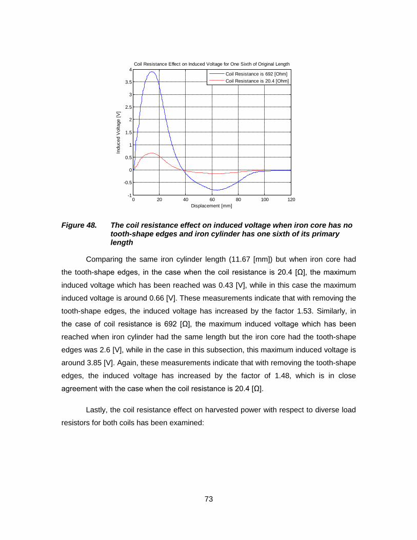
73
Figure 48. The coil resistance effect on induced voltage when iron core has no tooth-shape edges and iron cylinder has one sixth of its primary length
Comparing the same iron cylinder length (11.67 [mm]) but when iron core had
the tooth-shape edges, in the case when the coil resistance is 20.4 [Ω], the maximum
induced voltage which has been reached was 0.43 [V], while in this case the maximum
induced voltage is around 0.66 [V]. These measurements indicate that with removing the
tooth-shape edges, the induced voltage has increased by the factor 1.53. Similarly, in
the case of coil resistance is 692 [Ω], the maximum induced voltage which has been
reached when iron cylinder had the same length but the iron core had the tooth-shape
edges was 2.6 [V], while in the case in this subsection, this maximum induced voltage is
around 3.85 [V]. Again, these measurements indicate that with removing the tooth-shape
edges, the induced voltage has increased by the factor of 1.48, which is in close
agreement with the case when the coil resistance is 20.4 [Ω].
Lastly, the coil resistance effect on harvested power with respect to diverse load
resistors for both coils has been examined:
0 20 40 60 80 100 120-1
-0.5
0
0.5
1
1.5
2
2.5
3
3.5
4
Displacement [mm]
Indu
ced
Vol
tage
[V]
Coil Resistance Effect on Induced Voltage for One Sixth of Original Length
Coil Resistance is 692 [Ohm]Coil Resistance is 20.4 [Ohm]

74
Figure 49. The coil resistance effect on harvested power when iron core has no tooth-shape edges and iron cylinder has one sixth of its primary length: (a) coil resistance is 692 [Ω]; (b) coil resistance is 20.4 [Ω]
When the coil resistance is 692 [Ω], the maximum power is equal to:
].[320.5680
)902.1( 2
maxmWP ==
Moreover, figure (50) compares both powers which have been calculated
experimentally and the power versus load resistor graph which has been obtained
numerically.
0 20 40 60 80 100 120-0.5
0
0.5
1
1.5
2
Displacement [mm]
Induced V
oltage [
V]
One sixth of Original Length, Coil Resistance: 692 [Ohm], Load Resistance: 680 [Ohm]
0 20 40 60 80 100 120-0.1
-0.05
0
0.05
0.1
0.15
0.2
0.25
0.3
0.35
Displacement [mm]
Induced V
oltage [
V]
One Sixth of Original Length, Coil Resistance: 20.4 [Ohm], Load Resistance: 20 [Ohm]

75
Figure 50. Comparison between numerical analysis and experimental result for load powers with respect to variable load resistors when iron core has no tooth-shape edges and iron cylinder has one sixth of its primary length
Finally, when the coil resistance is 20.4 [Ω], the maximum power in this case is
equal to:
].[216.520
)323.0( 2
maxmWP ==
Comparing these results to the case when the iron cylinder had the same length
but the iron core had the tooth-shape edges, it can be concluded that when the coil
resistance is 692 [Ω], the maximum harvested power has increased by the factor 2.225,
which is almost equal to square of the factor that induced voltage has been increased
( )248.1 , while when the coil resistance is 20.4 [Ω], the maximum harvested power has
increased by the factor 2.321, which is also almost equal to square of the factor that
induced voltage has been increased in that case ( )253.1 .
3.4.3. Parameter study of energy harvester when there is no iron cylinder (iron core has no tooth-shape edges)
As the final experimental subsection, all of the experimental steps which have
been conducted in subsection (3.3.8) have been repeated again to demonstrate the
0 1000 2000 3000 4000 5000 6000 7000 8000 9000 100000
1
2
3
4
5
6
Load Resistor(ohm)
Load
Pow
er (m
W)
One Sixth Length, Coil Resistance: 692 (ohm)
Experimental ResultNumerical Result

76
effect of removing tooth-shape edges from iron core experimentally. First, the coil
resistance effect on induced voltage with respect to diverse velocities has been
examined for both coils:.
Figure 51. The coil resistance effect on induced voltage when iron core has no tooth-shape edges and there is no iron cylinder
Again, compare to the no iron cylinder case but when iron core had the tooth-
shape edges, in the case when the coil resistance is 20.4 [Ω], the maximum induced
voltage which has been reached was 0.39 [V], while in this case the maximum induced
voltage is around 0.56 [V]. These measurements indicate that with removing the tooth-
shape edges, the induced voltage has increased by the factor 1.44. Similarly, in the case
of coil resistance is 692 [Ω], the maximum induced voltage which has been reached
when iron cylinder had the same length but the iron core had the tooth-shape edges was
2.35 [V], while in the case in this subsection, this maximum induced voltage is around
3.35 [V]. Again, these measurements indicate that with removing the tooth-shape edges,
the induced voltage has increased by the factor of 1.42, which is in close agreement with
the case when the coil resistance is 20.4 [Ω].
Then, the coil resistance effect on harvested power with respect to diverse load
resistors for both coils has been examined:
0 20 40 60 80 100 120-1
-0.5
0
0.5
1
1.5
2
2.5
3
3.5
Displacement [mm]
Indu
ced
Vol
tage
[V]
Coil Resistance Effect on Induced Voltage for No Iron Cylinder
Coil Resistance is 692 [Ohm]Coil Resistance is 20.4 [Ohm]

77
Figure 52. The coil resistance effect on harvested power when iron core has no tooth-shape edges and there is no iron cylinder: (a) coil resistance is 692 [Ω]; (b) coil resistance is 20.4 [Ω]
Based on the impedance matching, when the coil resistance is 692 [Ω], the
maximum power is equal to: ].[955.3680
)640.1( 2
maxmWP ==
Same as before, figure (53) compares both powers which have been calculated
experimentally and the power versus load resistor graph which has been obtained
numerically.
0 20 40 60 80 100 120-0.5
0
0.5
1
1.5
2
Displacement [mm]
Induced V
oltage [
V]
No Iron Cylinder, Coil Resistance: 692 [Ohm], Load Resistance: 680 [Ohm]
0 20 40 60 80 100 120-0.1
-0.05
0
0.05
0.1
0.15
0.2
0.25
0.3
Displacement [mm]
Induced V
oltage [
V]
No Iron Cylinder, Coil Resistance: 20.4 [Ohm], Load Resistance: 20 [Ohm]

78
Figure 53. Comparison between numerical analysis and experimental result for load powers with respect to variable load resistors when iron core has no tooth-shape edges and there is no iron cylinder
At last, when the coil resistance is 20.4 [Ω], the maximum power in this case is
equal to:
].[781.320
)275.0( 2
maxmWP ==
Comparing these results to the case when there was no iron cylinder and the iron
core had the tooth-shape edges, it can be concluded that when the coil resistance is 692
[Ω], the maximum harvested power has increased by the factor 2.106, which is almost
equal to square of the factor that induced voltage has been increased ( )242.1 , while
when the coil resistance is 20.4 [Ω], the maximum harvested power has increased by the
factor 1.929, which is also almost equal to square of the factor that induced voltage has
been increased in that case ( )244.1 .
3.4.4. Conclusion
Based on all the steps which have been taken in this section, the following
graphs demonstrate the maximum voltage and maximum power versus the diverse
lengths of iron cylinder to determine the optimum length for the energy harvesting setup.
0 1000 2000 3000 4000 5000 6000 7000 8000 9000 100000
0.5
1
1.5
2
2.5
3
3.5
4
4.5
Load Resistor(ohm)
Load
Pow
er (m
W)
No Iron Cylinder, Coil Resistance: 692 (ohm)
Experimental ResultNumerical Result

79
(For illustrating the following graphs, the speed of moving coil is considered to be 70
[mm/s]).

80
(a)
(b)
Figure 54. The induced voltage and harvested power based on diverse lengths of iron cylinder when iron core has no tooth-shape edges: (a) induced voltage for both coils; (b) harvested power for both coils
0 1 2 3 4 5 6 71
2
3
4
Length (c m)
Max
imum
Indu
ced
Vol
tage (
Vol
t)
Coil Resistance: 692 (ohm)
0 1 2 3 4 5 6 70.2
0.3
0.4
0.5
0.6
0.7
Length (c m)
Max
imum
Indu
ced
Vol
tage (
Vol
t)
Coil Resistance: 20.4 (ohm)
0 1 2 3 4 5 6 70.5
1
1.5
2
2.5
3
3.5
4
4.5
5
5.5
Length (c m)
M a x
i m u
m P
o w e
r ( m
W )
Coil Resistance:692 [Ohm]Coil Resistance:20.4 [Ohm]

81
Again, based on above figure, the optimum length for iron cylinder in respect to
inducing maximum voltage and retrieving maximum power from electromagnetic energy
harvester is about 1.167 (cm), which verifies the other set of experimental tests that
have been conducted in section three of this chapter. Moreover, it can be seen that the
general behavior of both coils are in close agreement with each other. Although the coil
with higher resistance produces much more voltage comparing to the coil with lower
resistance, but the harvested power on load resistors for both coils are almost the same
as each other and generally the coil with higher resistance harvests power slightly more
than the coil with lower resistance. Finally, comparing this figure to figure (43), it can be
concluded that the maximum harvested power without tooth-shape edges on iron core is
5.320 [mW], which is enough amount to power sensors in condition monitoring for rotary
applications, while this maximum harvested power when the iron core has the tooth-
shape edges was 2.391 [mW]. Therefore, removing the tooth-shape edges from iron
core has increased the harvested power by the factor of 2.225.
Analyzing the three design modifications through experimental tests which has
been explained in sections 3.3 and 3.4 has been summarized in following tables:
Table 1. The effect of slope at the end of iron cylinder on induced voltage
The length of iron cylinder [mm] Induced voltage with slope [V] Induced voltage without slope [V]
Iron core has tooth-shape edges
35 1.8 1.6 23.33 2.2 2.1 17.5 2.45 2.35 14 2.45 2.35 11.67 2.6 2.5 Iron core doesn’t have tooth-shape edges
11.67 3.9 3.7

82
Table 2. The effect of internal coil resistance on induced voltage
The length of iron cylinder [mm] Induced voltage when coil resistance is 692 ohm [V]
Induced voltage when coil resistance is 20.4 ohm [V]
Iron core has tooth-shape edges
70 1.1 0.17
35 1.8 0.3
23.33 2.2 0.39
17.5 2.45 0.4
14 2.45 0.41
11.67 2.6 0.43
0 2.4 0.4 Iron core doesn’t have tooth-shape edges
70 1.41 0.23
11.67 3.9 0.66
0 3.35 0.56

83
Table 3. The maximum harvested power for both coils
The length of iron cylinder [mm] Harvested power through optimum load resistor when coil resistance is 692 ohm [mW]
Harvested power through optimum load resistor when coil resistance is 20.4 ohm [mW]
Iron core has tooth-shape edges
70 0.421 0.332
35 1.191 1.066
23.33 1.684 1.711
17.5 1.828 1.656
14 1.845 2.000
11.67 2.391 2.247
0 1.878 1.960
Iron core doesn’t have tooth-shape edges
70 0.690 0.583
11.67 5.320 5.216
0 3.955 3.781

84
4. One Degree of Freedom Electromagnetic Energy Harvester System for Rotary Motion
This chapter presents modeling and analysis of a voice coil energy harvester,
which is mounted on a rotary flexible beam that can be used as an energy scavenger for
rotary motion applications. The energy harvester system consists of a bimorph cantilever
beam with a voice coil as the tip mass mounted on a rotating hub. Assuming Euler–
Bernoulli beam equations and considering the effect of an electromagnetic transducer,
equations of motion are derived using the Lagrangian approach followed by relationships
describing the induced voltage. The equations provide a quantitative description of how
the hub acceleration and gravity due to the tip mass contribute power to the energy
harvester. Numerical simulations are performed to illustrate the performance of the
harvester by obtaining tip velocities and amplitudes for a range of rotational speeds and
to examine the effects of effective parameters on resonance frequency and induced
voltage, such as the spring constant and the load mass. Finally, the experimental test
has been done to demonstrate how much voltage can be collected by this method.
4.1. Mathematical Model of One Degree of Freedom Rotating Harvester
The electromagnetic energy harvester is the voice coil in the form of a speaker,
which comprise of permanent magnet, spring, and magnetic coil. The speaker is
mounted on one end of a cantilever beam. The other end of this cantilever beam is
connected to a rotating hub. The hub rotates with a constant speed. The general
schematic of the system is illustrated in following figure. To derive the mathematical
model, the energy harvester system has been divided into two subsystems: mechanical
subsystem and electrical subsystem. The main reason to create this division is that
kinetic energy harvesters, such as this one degree of freedom voice coil speaker rotating
harvester, require a transduction mechanism to generate electrical energy from motion

85
and the generator will require a mechanical system which couples environmental
displacements to the transduction mechanism. Based on this explanation, the
mechanical subsystem model relates the cantilever beam deflection to the relative
displacement between magnetic coil and permanent magnet. The electrical subsystem
model indicates the amount of induced voltage and harvested power in the moving coil.
First, the coupled dynamic equations of the rotating flexible beam have been derived
and then, the equation of generated electric voltage is derived.
Figure 55. One degree of freedom system for harvesting energy from rotary motion application
4.1.1. Mechanical Subsystem Model
In the energy harvester system, the gravity force on electromagnetic part of the
system (the speaker) and acceleration of the hub provide base excitation vibration for
the beam. The Euler-Bernoulli beam equation describes the partial differential equation
of vibrating beam as follows [60]:
(47) 0),(),(2
24
4
4
=∂
∂+
∂∂
ttwALtwEI ζρ
ζζ

86
where w is the deflection of the beam, ζ is the normalized position along the
length of the beam, which means Lx /=ζ , E is the Young’s modulus, I is the area
moment of inertia, ρ is the mass density, and A is the cross sectional area of the beam.
Using the method of separation of variables, w can be solved as
)().(),( tqftw ζζ = (48)
where f )(ζ and q(t) are the spatial and temporal coordinate systems. On the
other hand,
(49)
Equation (49) identifies the ith mode shape of the beam. The following boundary
conditions of equation (47) can be considered for a clamped-free beam to determine the
coefficients and β in equation (49):
,00
)( ==ζ
ζif
00
)(=
=ζζζ
ddfi
(50)
1)(
1)(
3
4
2
2
==
= ζζζ
ρβ
ζζζ
ddf
ALJ
dfd iLi
(51)
1)(
1)( 4
3
3
=−=
= ζζ
ρβ
ζζζ
iLi fAL
Mdfd
(52)
where LM and LJ are the mass and inertia of the speaker, respectively. Using
the above boundary conditions, the relation between the coefficients of equation (49) is
as follows:
βζβζβζβζζ coshsinhcossin)( 4321 aaaafi +++=

87
,31 aa −= 42 aa −= (53)
Moreover, the value of β can be obtained by solving the following equation:
0 )cosh cos -(1MJ )sinh cos cosh (sinJ - )sinh cos - cos (sinM - )cosh cos (1
43 =++
+
βββββββββββββββ
(54)
where ALMM L ρ/= and 3/ ALJJ L ρ= .
To derive a mathematical model that describes the energy harvester system, the
Lagrangian formulation has been used:
iiii
FpU
pT
pT
dtd
=∂∂
+∂∂
−∂∂ )(
(55)
where T is the total kinetic energy, U is the total potential energy, iF is the ith
generalized force, and ip is the ith generalized coordinate. The generalized force vector
is given by [ ]T00F = and the generalized coordinate vector is chosen as [ ]Tzqp = ,
where z is the relative displacement between magnetic coil and permanent magnet.
To obtain the total kinetic energy of the energy harvester system, first we need to
calculate the kinetic energy of different components of the system. The kinetic energy of
the beam is given by:
(56)
where bJ is the beam inertia.
dmxwwJTbeambbeam )2(
21
21 22 θθ ++= ∫

88
For the electromagnetic part (the speaker), x = L, w(x,t) = w(L,t), and
),(),( tLwtxw = . Since for the electromagnetic part, the kinetic energy is comprised of
translational and rotational components, therefore:
(57)
2)(21
xwJT e
lrotational ∂∂
+=θ
(58)
The total kinetic energy of the harvester system is equal to the summation of all
three above kinetic energies, which means:
rotationalnalTranslatiobeamTotal TTTT ++= (59)
The expression for the total potential energy (U) is as follows:
2
0
22
2
0
)(21)sintansintansin
coscos(
)sintansincos
(
)sin)tan(cos
()(2
zwkzwLzwmg
wLwMg
dxwxwAgdxxwEIU
se
e
LL
++−−++
+−+
+−++∂∂
= ∫∫
θθθθθθθ
θθθθ
θθθ
ρ
(60)
Finally, the dynamic equations of the beam can be presented in matrix form as
follows:
=+
+
+
00
Szq
Kzq
Czq
M
(61)
where:
])()([21])([
21 222222 θθθθ LzwzwmLwwMT eeeenalTranslatio +++++++=

89
′++= ∫mmf
mffLJfMdfALM
LL
22
21
0
2 )( ξξρ
(62)
+=
mm
mmb
cfcfcfcc
C2)(
(63)
+−+−
+−+−′′= ∫
ss
ssL
kmfkfm
fkfmfkfMdfLEI
K22
22221
0
23 )(
θθ
θθξξ
(64)
+= ∫θ
ξξθρθcos
)(coscos 10
mgdfALggfMS L (65)
In the above equations, m is the mass of the voice coil, sk is the spring constant,
and bc and mc are the damping coefficients for the beam and for the voice coil,
respectively.
4.1.2. Electrical Subsystem Model
The equation of motion for base excitation of second-order mass-spring-damper
system is:
)()()()( tymtkztzctzm T −=++ (66)
where y is the base displacement, z is the relative displacement between
permanent magnet and magnetic coil, k is the spring stiffness, m is the voice coil mass,
and Tc is the total amount of damping. On the other hand, it has been discussed in
chapter 2 that when a magnetic source, like permanent magnet, and a conductor, like
coil, has a relative displacement with respect to each other, then based on Faraday’s

90
law, there would be an induced voltage in conductor which can be calculated through
following equation:
(67)
Suppose the magnetic flux density (B) is uniformed radial in the area of moving
coil, and the coil moves perpendicular to the magnetic flux density (B) direction.
Therefore, equation (67) can be rewritten as:
(68)
where l and u are the length and velocity of the coil, respectively.
4.2. Numerical analysis of one degree of freedom rotating harvester
This section presents numerical results to evaluate the feasibility of the energy
harvesting system for the rotary motion applications. By solving equations (61) and (68)
simultaneously for variable z, the simulation result is as follows:
∫ ×= dlBuV ).(
ulBV ..=

91
Figure 56. Frequency response of induced voltage which caused by relative displacement between permanent magnet and magnetic coil of voice coil speaker
Based on figure (56), the resonance frequency of voice coil speaker occurs at
170 [rad/s] and the maximum induced voltage is around 6.75 [mV], which is considerably
low to harvest power from it.
Now, the effect of some effective parameters on frequency response has been
examined. First of all, the effect of spring constant of the voice coil speaker on frequency
response for three different spring constants has been simulated and the result is
demonstrated in following figure:

92
Figure 57. Spring constant effect on frequency response for one degree of freedom system
As it can be seen, softer springs will result in lower resonance frequencies as it
expected. Moreover, it should be mention that the total load mass (voice coil speaker)
comprises of the mass of the moving coil and spring inside speaker ( sM ) and the mass
of fixed magnet and the body of the speaker ( rM ). The weight distribution between
these two parts of the total mass will affect the frequency response of this one degree of
freedom rotary electromagnetic energy harvester. The simulation result to analyze the
effect of this mass distribution is demonstrated below:

93
Figure 58. The effect of load mass distribution on frequency response of one degree of freedom electromagnetic rotary energy harvester
Above figure illustrates that increasing the mass distribution on fixed magnet and
the body part of the speaker ( rM ) will result in both higher resonant frequency and
higher voltage peak.
4.3. Experimental test of one degree of freedom rotating harvester
To demonstrate how much voltage can be collected by this one degree of
freedom system, the experimental setup was going to be tested with the geometric and
material parameters of the bimorph cantilever which are given in the following table.
Table 4. Characteristics of the experimental beam-mass system
Parameters Beam Material Spring steel Young’s modulus, E (GN/m2) 210 Length, L (mm) 61 Width, b (mm) 38.1

94
Thickness, t (mm) 0.5 Mass density, ρ ( 3/ mkg ) 7850 Load mass, LM (kg) 0.022
To explain the experiment procedure, the experimental setup should be tested in
diverse angular velocities. Since the induced voltage through voice coil is sinusoidal, to
obtain its Fourier transform, the maximum induced voltage in each frequency should be
identified to obtain a point in frequency domain. Then with repeating this procedure for
all frequencies, the frequency response of induced voltage within the voice coil will
obtain by the curve fitting through all these points.
First, to identify the characteristics of this one degree of freedom system, the
voice coil speaker has been placed on shaker and the base excitation response of this
speaker is demonstrated in following figure:
Figure 59. Frequency response of induced voltage - Experimental result for one degree of freedom system
Figure (59) illustrates that the resonance frequency of voice coil energy harvester
occurs at 27.67 [Hz], but the maximum induced voltage is equal to 0.0066 [V], which is
really negligible amount to harvest power on loads. Hence, on the next chapter, the two
degrees of freedom system which comprises of linear voice coil motors are going to be

95
introduced since these linear voice coil motors are able to produce much higher voltages
than voice coil speakers even in low frequencies.
4.4. Conclusion
The design of an electromagnetic energy harvester for rotary motion applications
is discussed in this chapter. The electromagnetic energy harvester consists of a
cantilever beam carrying a voice coil as tip mass, with the whole system mounted on a
rotating horizontal hub. The proposed energy harvester has an inherent source of
harmonic force due to the gravitational force of the tip mass. When the hub rotates with
a constant angular speed, the gravity force on the tip and its coupling with rotational
motion causes the mass-beam system to vibrate. A multimode mathematical model for
the coupled electromechanical system is derived by using the method of assumed
modes. Then the experimental analysis has been conducted to demonstrate how much
voltage can be collected by this one degree of freedom system. Since the maximum
induced voltage was really low (around 0.0066 [V]), thus the amount of harvesting power
on loads is negligible. Therefore, in the next step, the two degrees of freedom system
which comprises of linear voice coil motors are going to be introduced since these linear
voice coil motors are able to produce much higher voltages than voice coil speakers
even in low frequencies.

96
5. Two Degree of Freedom Electromagnetic Energy Harvester System for Rotary Motion
In this chapter, based on the design concepts of previous chapters, a system
with two degree of freedom has been introduced. Then, this system has been placed on
shaker to identify its characteristics to use it in rotary motion applications. Finally, this
system has been mounted on a car ring to demonstrate the results experimentally.
5.1. Describing the Two Degree of Freedom Rotating Harvester System
The two degrees of freedom system is comprised of two linear voice coil motors
which are connected to each other through a spring, called the connecting spring. As will
be presented later in system identification, the stiffness of this connecting spring will
determine the bandwidth of the frequency response of the system. Moreover, a small
spring has been placed inside each of linear voice coil motors to make each voice coil to
resonate. The schematic of the described system has been demonstrated in following
figure. One of the most significant advantages of the two degrees of freedom system
over one degree of freedom system is that the bandwidth of two degrees of freedom
system, which can capture relatively high voltage, is much broader than one degree of
freedom system. This important advantage enables us to harvest electrical power not
only at a specific frequency, but also at wide range of car ring’s speeds, which is going
to be more practical in real world. In other words, adding one more degree of freedom to
the electromagnetic rotary harvester will result in a generator which is less sensitive to a
specific frequency.
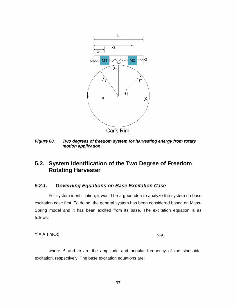
97
Figure 60. Two degrees of freedom system for harvesting energy from rotary motion application
5.2. System Identification of the Two Degree of Freedom Rotating Harvester
5.2.1. Governing Equations on Base Excitation Case
For system identification, it would be a good idea to analyze the system on base
excitation case first. To do so, the general system has been considered based on Mass-
Spring model and it has been excited from its base. The excitation equation is as
follows:
Y = A sin(ωt) (69)
where A and ω are the amplitude and angular frequency of the sinusoidal
excitation, respectively. The base excitation equations are:

98
(70)
where 1M is the total mass of first coil (10.4 [gr]), 2M is the total mass of
second coil (9.9 [gr]), 1K and 3K are the spring constants of the small springs inside the
linear voice coil motors, and 2K is the spring constant of the connecting spring. At the
next step, the experimental results for base excitation test among the effect of
connecting spring stiffness on frequency response have been examined.
5.2.1.1. Examining the Two Degree of Freedom Rotating Harvester when the Connecting Spring is Soft
The setup has been placed on shaker to determine the frequency response of
both coils. The shaker excitation was sinusoidal with 0.4 [mm] amplitude and the
frequency sweeps from 5 to 300 [Hz]. The results are demonstrated below:
(a) (b)
Figure 61. The frequency responses of: (a) first linear voice coil motor, and (b) second linear voice coil motor; when the connecting spring is soft
For the first coil, the first peak happens at 42 [Hz] with 0.496 [V] amplitude and
the second peak places at 263 [Hz] with 0.748 [V] amplitude, while for the second coil,
the first peak happens at 42 [Hz] with 0.543[V] amplitude and the second peak occurs at
=
+−
−++
0.
)()(
00 1
2
1
322
221
2
1
2
1 YKXX
KKKKKK
XX
MM

99
263 [Hz] with 0.832 [V] amplitude. Therefore, the bandwidth of the frequency response in
this case is equal to 263-42 = 221 [Hz].
5.2.1.2. Examining the Two Degree of Freedom Rotating Harvester when the Connecting Spring is Stiff
The setup has been placed on shaker to determine the frequency response of
both coils. The shaker excitation was sinusoidal with 0.4 [mm] amplitude and the
frequency sweeps from 5 to 600 [Hz]. The results are demonstrated below:
(a) (b)
Figure 62. The frequency responses of: (a) first linear voice coil motor, and (b) second linear voice coil motor; when the connecting spring is stiff
Again, for the first coil, the first peak happens at 58 [Hz] with 0.5 [V] amplitude
and the second peak places at 445 [Hz] with 1.07 [V] amplitude, while for the second
coil, the first peak happens at 58 [Hz] with 0.39[V] amplitude and the second peak
occurs at 445 [Hz] with 1.3 [V] amplitude. This time, in this case, the bandwidth of the
frequency response is equal to 445-58 = 387 [Hz], which is 166 [Hz] more than the
previous case when connecting spring was softer. Thus, it can be concluded that the
bandwidth can be increased by stiffer connecting spring.

100
5.3. Testing the two degree of freedom energy harvesting system on rotary application
5.3.1. The governing equations on rotary motion case
This section presents mathematical modeling of the two degrees of freedom
energy harvester system which has been mounted on a rotary ring and consists of linear
voice coil motors and springs. The ring rotates with a constant speed. Considering the
effect of an electromagnetic induction, equations of motion are derived using the
Lagrangian approach followed by relationships describing the harvested power. The
equations provide a quantitative description of how the ring acceleration, gravity force,
and relative displacement between permanent magnet and coil contribute power to the
energy harvester. To derive the mathematical model, the energy harvester system has
been analyzed from two different perspectives: mechanical perspective and electrical
perspective. The mechanical perspective relates the ring’s rotation to the relative
displacement between coil and permanent magnet. The electrical perspective indicates
the amount of induced voltage and harvested power in the moving coil. Since in the
electrical perspective, the same governing equations as the electrical subsystem model
of one degree of freedom system rule, thus in this section, only the coupled dynamic
equations of the rotating ring have been derived and equation (68) can also be used for
calculating the amount of induced voltage across moving coils in this two degrees of
freedom system. To derive a mathematical model that describes the energy harvester
system, the Lagrangian formulation has been used, which has been mentioned here
again for the convenience:
iiii
FpU
pT
pT
dtd
=∂∂
+∂∂
−∂∂ )(
(71)
where T is the total kinetic energy, U is the total potential energy, iF is the ith
generalized force, and ip is the ith generalized coordinate. The generalized force vector
is given by [ ]T000 = F and the generalized coordinate vector is chosen as
[ ]TXX 21= p θ , where θ is the angular displacement of car’s ring, 1X is the
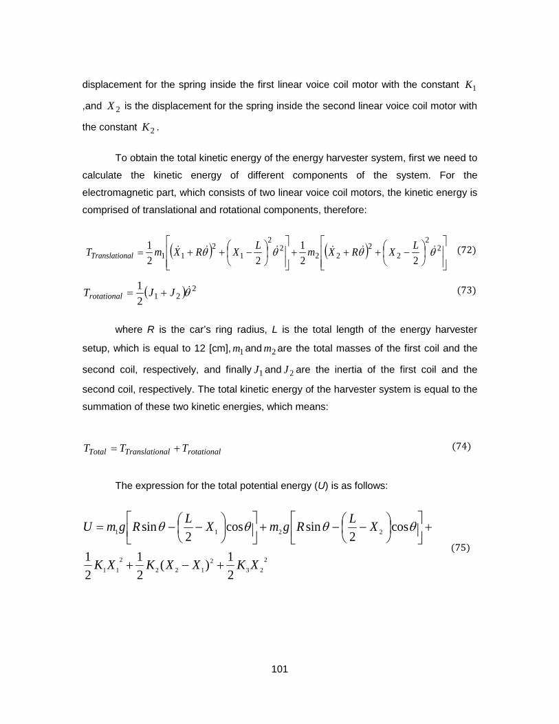
101
displacement for the spring inside the first linear voice coil motor with the constant 1K
,and 2X is the displacement for the spring inside the second linear voice coil motor with
the constant 2K .
To obtain the total kinetic energy of the energy harvester system, first we need to
calculate the kinetic energy of different components of the system. For the
electromagnetic part, which consists of two linear voice coil motors, the kinetic energy is
comprised of translational and rotational components, therefore:
(72)
( ) 2212
1 θJJTrotational += (73)
where R is the car’s ring radius, L is the total length of the energy harvester
setup, which is equal to 12 [cm], 1m and 2m are the total masses of the first coil and the
second coil, respectively, and finally 1J and 2J are the inertia of the first coil and the
second coil, respectively. The total kinetic energy of the harvester system is equal to the
summation of these two kinetic energies, which means:
rotationalnalTranslatioTotal TTT += (74)
The expression for the total potential energy (U) is as follows:
223
2122
211
2211
21)(
21
21
cos2
sincos2
sin
XKXXKXK
XLRgmXLRgmU
+−+
+
−−+
−−= θθθθ
(75)
( ) ( )
−+++
−++= 2
2
22
222
2
12
11 221
221 θθθθ LXRXmLXRXmT nalTranslatio

102
5.3.2. Numerical analysis of two degree of freedom rotating harvester
This section presents numerical results to evaluate again the feasibility of the two
degrees of freedom energy harvesting system for the rotary motion applications. By
solving equations (74), (75), and (68) from last chapter simultaneously for variable 1X ,
the simulation result is as follows:
Figure 63. Simulation result for two degrees of freedom system
This figure illustrates that the two degrees of freedom system has two peaks; the
first one occurs at 16 [Hz] with the amplitude 0.18 [V] and the second one is at 27 [Hz]
with the amplitude 0.315 [V].
Then to obtain the numerical graph of harvested power through this two degree
of freedom system, again equation (44) has been used and the result is as follows:
0 5 10 15 20 25 30 350.1
0.15
0.2
0.25
0.3
0.35
Frequency(Hz)
volta
ge(V
)
2DOF System
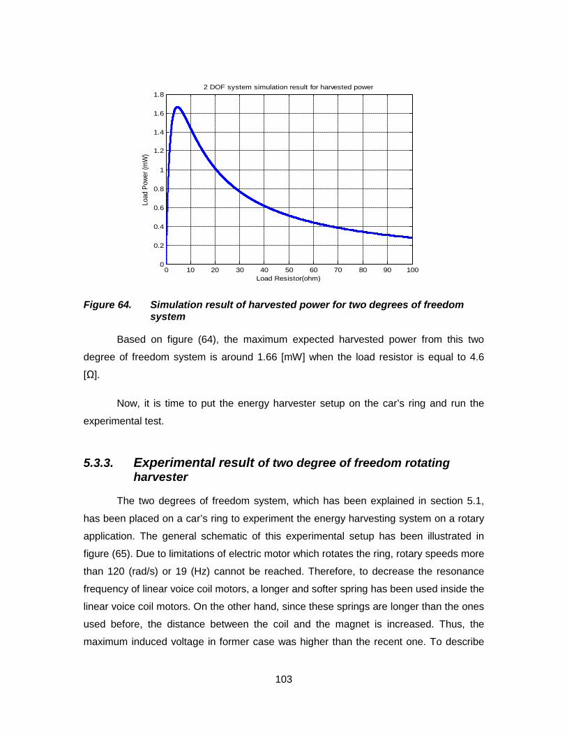
103
Figure 64. Simulation result of harvested power for two degrees of freedom system
Based on figure (64), the maximum expected harvested power from this two
degree of freedom system is around 1.66 [mW] when the load resistor is equal to 4.6
[Ω].
Now, it is time to put the energy harvester setup on the car’s ring and run the
experimental test.
5.3.3. Experimental result of two degree of freedom rotating harvester
The two degrees of freedom system, which has been explained in section 5.1,
has been placed on a car’s ring to experiment the energy harvesting system on a rotary
application. The general schematic of this experimental setup has been illustrated in
figure (65). Due to limitations of electric motor which rotates the ring, rotary speeds more
than 120 (rad/s) or 19 (Hz) cannot be reached. Therefore, to decrease the resonance
frequency of linear voice coil motors, a longer and softer spring has been used inside the
linear voice coil motors. On the other hand, since these springs are longer than the ones
used before, the distance between the coil and the magnet is increased. Thus, the
maximum induced voltage in former case was higher than the recent one. To describe
0 10 20 30 40 50 60 70 80 90 1000
0.2
0.4
0.6
0.8
1
1.2
1.4
1.6
1.8
Load Resistor(ohm)
Load
Pow
er (m
W)
2 DOF system simulation result for harvested power

104
the experiment procedure, the experimental setup has been tested on diverse angular
velocities. Since the induced voltage through energy harvesting system is sinusoidal, to
obtain its Fourier transform, the maximum induced voltage in each frequency has been
identified to obtain a point in frequency domain. Then the best curve is fitted through
these points to indicate the frequency response of induced voltage within voice coil.

105
Motor to create rotary motion
Car’s ring
Energy harvester setup
Slip ring
(a)
Linear voice coil motors with permanent magnet & spring inside them
Moving coils Connecting spring
(b)
Figure 65. The schematic of the experimental setup for two degrees of freedom system: (a) the general setup; (b) details of energy harvester components
Repeating this procedure for all frequencies, the frequency response of induced
voltage is obtained as follows:

106
Figure 66. Frequency response of induced voltage - Experimental result
Figure (66) illustrates that the resonance frequency of energy harvester occurs at
15 (Hz), and the induced voltage’s peak is equal to 0.175 Volt. Again it should be
mentioned that the second voltage peak which occurs at higher rotational speeds cannot
be reached due to limitations of experimental setup.
6 8 10 12 14 16 180
0.05
0.1
0.15
0.2
0.25
Frequency (Hz)
Indu
ced
Vol
tage
(Vol
t)
Rotary Motion

107
6. Conclusion
Energy harvesting converts the unused ambient energy in the environment into
electricity. Numerous potential sources for power harvesting exist such as light, thermal
gradient, and vibration (motion). In this thesis, both linear and rotary motions are used as
a power source. Three types of vibration motion to electricity converters have been
considered so far: electromagnetic, piezoelectric, and electrostatic. After a preliminary
investigation and comparison, electromagnetic method was chosen to be applied as an
energy harvester for both linear and rotary motion applications.
In the electromagnetic converter, the relative motion between a coil and magnetic
field causes an induced voltage in the coil. After deriving the governing equations on the
modified voice coil electromagnetic energy harvester, the new design has been
introduced and the parameter study on diverse components of energy harvester setup
has been conducted. In this parameter study, the effects of three design modifications
on induced voltage and harvested power have been examined through simulation
analysis and it has been demonstrated that applying those three design modifications
will improve the amount of induced voltage by %50. In this simulation analysis, a pattern
for the magnetic flux density lines has been illustrated and the result indicates that the
magnetic field is well concentrated on the coil area, thus this setup is able to capture and
convert most of the available kinetic energy into electricity. After simulation analysis, this
newly designed energy harvester setup has been fabricated to verify simulation results
experimentally. For linear motion application, the experimental results indicate that when
the coil movements’ speed is 70 [mm/s], the maximum harvested power through
impedance matching with coil’s internal resistance is 5.320 [mW]. The next step in this
research area is to use a spring in the electromagnetic energy harvester for linear
motions to make the system resonate and tune the resonance frequency of energy
harvester system to the natural frequency of vibration source to maximize the harvesting
power.
108
For rotary motion application, when one degree of freedom system such as voice
coil speaker is used, the resonance frequency occurs in relatively high frequencies,
which are not achievable in many rotary applications, therefore it has been tried to
reduce the resonance frequency of the speaker. But since in lower resonance
frequencies, the maximum induced voltage has decreased dramatically, thus in next
step, the two degrees of freedom energy harvesting system for rotary motion
applications has been introduced. Although the resonance frequency of the two degrees
of freedom system was still relatively high, but since the induced voltage across the
moving coils in this system was relatively higher than one degree of freedom system,
hence when the resonance frequency has been reduced by adding additional masses
and decreasing the stiffness of springs, this two degrees of freedom system still has
produced reasonable amount of voltage in low frequencies. This two degrees of freedom
system is comprised of two linear voice coil motors which are connected to each other
through a spring, called the connecting spring. The stiffness of this connecting spring will
determine the bandwidth of the frequency response of the system. Moreover, a small
spring has been placed inside each of linear voice coil motors to make each voice coil to
resonate. This system has been mounted on a car ring to demonstrate the amount of
reachable induced voltage by this system experimentally. The result illustrated that at
the resonant frequency (15 [Hz]), the induced voltage was 0.175 [V] for each coil.
Therefore, if these two coils have been connected to each other as series voltage
sources, the total induced voltage across two degrees of freedom system is 0.35 [V].
Note that since in this two degree of freedom system, the second voltage peak which
occurs at higher rotational speeds cannot be reached due to limitations of experimental
setup, therefore the next step in this research area could be to decrease the resonance
frequencies of the system more than the current implemented setup in order to use both
voltage peaks and hence more bandwidth of the two degree of freedom electromagnetic
rotating harvester.

109
References
[1] Amirtharajah, R., and Chandrakasan, A. P., 1998, “Self-powered signal processing using vibration-based power generation”, IEEE J. Solid State Circuits 33, pp. 687-695.
[2] Koeneman P B, Busche-Vishniac I J, Wood K L, 1997, “Feasibility of micro power supplies for MEMS”, IEEE J. Microelectomechanical Systems 6, 355-362.
[3] Jacobson S A, Epstein A H, 2003, “An informal survey of power MEMS”, Proc. The Int. Symp. on Micro-Mechanical Engineering (ISMME), Japan, K18.
[4] Koeneman P B, Busche-Vishniac I J and Wood K L 1997, Feasibility of micro power supplies for MEMS IEEE J. Microelectomech. Syst. 6 355–62
[5] G¨orge G, Kirstein M and Erbel R 2001, Microgenerators for energy autarkic pacemakers and defibrillators: fact or fiction Herz 26 64–8
[6] Jacobson S A and Epstein A H 2003, An informal survey of power MEMS Proc. Int. Symp. on Micro-Mechanical Engineering ISMME (Japan) p K18
[7] Banazwski B and Shah R K 2003, The role of fuel cells for consumer electronic products and toys Proc. 1st Int. Conf. on Fuel Cell Science, Engineering and Technology (Rochester, NY, USA) pp 149–55
[8] Epstein A H 2004, Millimeter-scale, micro-electro-mechanical systems gas turbine engines J. Eng. Gas Turbines Power 126 205–26
[9] Tanaka S, Changa K-S, Mina K-B, Satoh D, Yoshida K and Esashi M 2004, MEMS-based components of a miniature fuel cell/fuel reformer system Chem. Eng. J. 101 143–9
[10] Kiely J J, Morgan D V and Rowe D M 1991, Low cost miniature thermoelectric generator Electron. Lett. 27 2332–4
[11] Schaevitz S B, Franz A J, Jensen K F and Schmidt M A 2001, A combustion-based MEMS thermoelectric power generator Proc. 11th Int. Conf. on Solid-State Sensors and Actuators, Transducers 01 (Munich, Germany) p 1A3-02
[12] Zhang C, Najafi K, Bernal L P and Washabaugh P D 2001, An integrated combustor-thermoelectric micro power generator Proc. 11th Int. Conf. on Solid-State Sensors and Actuators, Transducers 01 (Munich, Germany) p 1A3–03

110
[13] Erick O. Torres and Gabriel A. Rincon-Mora, Harvesting ambient energy, http://users.ece.gatech.edu/rincon-mora/publicat/trade_jrnls/ee_times_0805_harvest.pdf
[14] Shad Roudy, Paul K. Wright and Kristofer Pister, Micro-electrostatic vibration-to-electricity converters, Proceedings of IMECE2002,ASME International Mechanical Engineering Congress & Exposition, November 17-22, 2002
[15] Meninger S 1999, A low power controller for a MEMS based energy converter, MSc Massachusetts Institute of Technology
[16] Roundy S, Wright P and Pister K 2002, Micro-electrostatic vibration-to-electricity converters, Proc. IMECE 2002 pp 1–10
[17] Roundy S 2003, Energy scavenging for wireless sensor nodes with a focus on vibration to electricity conversion, PhD Thesis University of California, Berkeley
[18] Meninger S, Mur-Miranda J, Lang J, Chandrakasan A, Slocum A, Schmidt M and Amirtharajah R 2001, Vibration to electric energy conversion, IEEE Trans Very Large Scale Integration (VLSI) Syst. 9 64–76
[19] Despesse G, Jager T, Chaillout J, Leger J, Vassilev A, Basrour S and Chalot B 2005, Fabrication and characterisation of high damping electrostatic micro devices for vibration energy scavenging, Proc. Design, Test, Integration and Packaging of MEMS and MOEMS pp 386–90
[20] Miyazaki M, Tanaka H, Ono G, Nagano T, Ohkubo N, Kawahara T and Yano K 2003, Electric-energy generation using variable-capacitive resonator for power-free LSI: efficiency analysis and fundamental experiment, ISLPED ’03 pp 193–8
[21] Sterken T, Baert K, Puers R and Borghs S, Power extraction from ambient vibration, Proc. 3rd Workshop on Semiconductor Sensors and Actuators pp 680–3
[22] Sterken T, Fiorini P, Baert K, Borghs G and Puers R 2004, Novel design and fabrication of a MEMS electrostatic vibration scavenger, Power MEMS Conference (Kyoto Japan) pp 18–21
[23] Arakawa Y, Suzuki Y and Kasagi N 2004, Micro seismic power generator using electret polymer film, Power MEMS Conference (Kyoto, Japan) pp 187–90
[24] Peano F and Tambosso T 2005, Design and optimisation of a MEMS electret-based capacitive energy scavenger, J. Microelectromech. Syst. 14 435–529
[25] Erick O. Torres and Gabriel A. Rincon-Mora, Harvesting ambient energy will make embedded devices autonomous, http://www.embedded.com/showArticle.jhtml?articleID=170102227
[26] Nye J F 1957, Physical Properties of Crystals (Oxford: Oxford University Press)

111
[27] Baudry H 1987, Screen-printing piezoelectric devices, Proc. 6th European Microelectronics Conference (London, UK), pp 456–63
[28] White N M and Turner J D 1997, Thick-film sensors: past, present and future, Meas. Sci. Technol. 8 1–20
[29] Lovinger A J 1983, Ferroelectric polymers, Science 220 1115–21
[30] S P Beeby, M J Tudor, and N M White 2006, Energy harvesting vibration sources for microsystems applications, Measurement Science and Technology.17, R175-R195
[31] Shad Roudy and Paul Wright, 2002, A piezoelectric vibration based generator for wireless electronics, Smart Materials and Structures, Volume 13, pp.1131-1144
[32] Umeda M, Nakamura K and Ueha S 1996, Analysis of the transformation of mechanical impact energy to electric energy using piezoelectric vibrator, Japan. J. Appl. Phys. 35 3267–73
[33] Kymissis J, Kendall C, Paradiso J and Gershenfeld N 1998, Parasitic power harvesting in shoes, Proc. 2nd IEEE Int. Conf. Wearable Computing (California) pp 132–9
[34] White N M, Glynne-Jones P and Beeby S P 2001, A novel thick-film piezoelectric micro-generator, Smart Mater. Struct. 10 850–2
[35] Glynne-Jones P, Beeby S P and White N M 2001, Towards a piezoelectric vibration powered microgenerator, IEE Proc.—Sci. Meas. Technol. 148 68–72
[36] Glynne-Jones P, Beeby S P and White N M 2001, The modelling of a piezoelectric vibration powered generator for Microsystems, Proc. 11th Int. Conf. on Solid-State Sensors and Actuators, Transducers 01 (Munich, Germany) pp 46–9
[37] Beeby S P, Blackburn A and White N M 1999, Processing of PZT piezoelectric thick films on silicon for microelectromechanical systems, J. Micromech. Microeng. 9 218–29
[38] Torah R, Beeby S and White N 2005, An improved thick-film piezoelectric material by powder blending and enhanced processing parameters, IEEE Trans. UFFC 52 10–16
[39] Jeon Y B, Sood R, Jeong J-h and Kim S G 2005, MEMS power generator with transverse mode thin film PZT, Sensors Actuators A 122 16–22
[40] Sodano H A, Park G, Leo D J and Inman D J 2003, Use of piezoelectric energy harvesting devices for charging batteries, Proc. SPIE 10th Annual Int. Symp. on Smart Structures and Materials (San Diego, CA, USA) pp 101–8

112
[41] Sodano H A, Park G and Inman D J 2003, An investigation into the performance of macro-fiber composites for sensing and structural vibration application, Mech. Syst. Signal Process. 18 683–97
[42] Wilkie W K, Bryant R G, High J W, Fox R L, Hellbaum R F, Jalink A, Little B D and Mirick P H 2000, Low cost piezocomposite actuator for structural control applications, Proc. 7th SPIE Int. Symp. on Smart Structures and Materials (Newport Beach, CA) pp 323–34
[43] Gorge G, Kirstein M and Erbel R 2001, Microgenerators for energy autarkic pacemakers and defibrillators: fact or fiction Herz.
[44] Shad Roudy PhD thesis, May 2003, Energy scavenging for wireless sensor nodes with a focus on vibration to electricity conversion, University of California at Berkeley, Berkeley CA
[45] Roundy, S., Wright, P. K., and Rabaye, J., 2003, “A study of low level vibrations as a power source for wireless sensor nodes”, Computer Communications 26, pp. 1131-1144
[46] Glynne-Jones, P., Tudor, M.J., Beeby, S.P., and White, N.M., 2004, “An electromagnetic, vibration-powered generator for intelligent sensor systems”, Sens. Actuators A110(1-3), pp. 344-349
[47] Von Buren, T., and Troster, G., 2007, “Design and optimisation of a linear vibration-driven electromagnetic micro-power generator”, Sens. Actuators A 135, pp. 765-775
[48] Williams, C.B., and Yates, R.B., 1995, “Analysis of a micro-electric generator for microsystems”, Transducers 95/Eurosensors IX, pp. 369-372
[49] Hadas Z, Kluge M, Singule V, Ondrusek C, 2007, “Electromagnetic vibration power generator”, IEEE Int Symp Diagnostics for Electric Machines, Power Electronics and Drives: 451-455
[50] Bayrashev A, Robbins W P and Ziaie B 2004, Low frequency wireless powering of microsystrems using piezoelectric-magnetostrictive laminate composites, Sensors Actuators A 114 244–9
[51] Jiles, David, 1991, Introduction to Magnetism and Magnetic Materials, Chapman and Hall, Chap. 1
[52] Franklin, Jerrold, 2005, Classical Electromagnetism, Pearson Addison Wesley, Chap. 3
[53] Lorrain, Paul, and Corson, Dale R., 1990, Electromagnetism: Principles and Applications, W. H. Freeman and company, Chap. 5
[54] Coey, J. M. D., 2010, Magnetism and Magnetic Materials, Cambridge University Press, Chap. 4

113
[55] Cheng, D. K., 1989, Field and Wave Electromagnetics, second edition, Addison-Wesley publishing company,Chap. 7
[56] Ida, Nathan, and Bastos, Joao, 1997, Electromagnetics and Calculation of Fields, second edition, Springer, Chap. 5
[57] Di Bartolo, Baldassare, 2004, Classical Theory of Electromagnetism, second edition, World Scientific, Chap. 2
[58] Knoepfel, Heinz, 2000, Magnetic Fields: a comprehensive theoretical treatise for practical use, Wiley-Interscience, John Wiley & sons, Inc., Chap. 1
[59] http://www.kjmagnetics.com/proddetail.asp?prod=RX8CC
[60] Khameneifar, F., and Arzanpour, S., 2008, “Energy Harvesting From Pneumatic Tires Using Piezoelectric Transducers,” ASME Conference Proceedings of SMASIS 2008, Paper No. 426, pp. 333–339