Design and Implementation of a PowerPC and AltiVec Backend with
50
Design and Implementation of a PowerPC and AltiVec Backend with Optimizations by Matthew W. Deeds B.S., Electrical Engineering and Computer Science, Massachusetts Institute of Technology (2000) Submitted to the Department of Electrical Engineering and Computer Science in partial fulfillment of the requirements for the degree of Master of Engineering in Electrical Engineering and Computer Science at the MASSACHUSETTS INSTITUTE OF TECHNOLOGY September 2001 c Matthew W. Deeds, MMI. All rights reserved. The author hereby grants to MIT permission to reproduce and distribute publicly paper and electronic copies of this thesis document in whole or in part, and to grant others the right to do so. Signature of Author ............................................................... Department of Electrical Engineering and Computer Science August 31, 2001 Certified by ........................................................................ Saman Amarasinghe, Associate Professor Thesis Supervisor Accepted by ....................................................................... Arthur C. Smith Chairman, Department Committee on Graduate Theses
Transcript of Design and Implementation of a PowerPC and AltiVec Backend with

Design and Implementation of a PowerPC and AltiVec
Backend with Optimizations
by
Matthew W. Deeds
B.S., Electrical Engineering and Computer Science,
Massachusetts Institute of Technology (2000)
Submitted to the Department of Electrical Engineering and Computer Science
in partial fulfillment of the requirements for the degree of
Master of Engineering in Electrical Engineering and Computer Science
at the
MASSACHUSETTS INSTITUTE OF TECHNOLOGY
September 2001
c© Matthew W. Deeds, MMI. All rights reserved.
The author hereby grants to MIT permission to reproduce and distribute publicly
paper and electronic copies of this thesis document in whole or in part, and to grant
others the right to do so.
Signature of Author . . . . . . . . . . . . . . . . . . . . . . . . . . . . . . . . . . . . . . . . . . . . . . . . . . . . . . . . . . . . . . .
Department of Electrical Engineering and Computer Science
August 31, 2001
Certified by. . . . . . . . . . . . . . . . . . . . . . . . . . . . . . . . . . . . . . . . . . . . . . . . . . . . . . . . . . . . . . . . . . . . . . . .
Saman Amarasinghe, Associate Professor
Thesis Supervisor
Accepted by . . . . . . . . . . . . . . . . . . . . . . . . . . . . . . . . . . . . . . . . . . . . . . . . . . . . . . . . . . . . . . . . . . . . . . .
Arthur C. Smith
Chairman, Department Committee on Graduate Theses

Design and Implementation of a PowerPC and AltiVec Backend withOptimizations
byMatthew W. Deeds
Submitted to the Department of Electrical Engineering and Computer Scienceon August 31, 2001, in partial fulfillment of the
requirements for the degree ofMaster of Engineering in Electrical Engineering and Computer Science
Abstract
Advances in microprocessor design have resulted in both improvements in speed as well as
new architecture features. These features add complexity to the processor design, along
with complexity to the compiler tool chain.
We examined the effects of a modern microprocessor on the compiler tool chain. By
implementing a backend for a processor that has a modern central processing unit and
multimedia unit, we analyze some specific processor features that effect the tool chain.
To achieve this goal we implemented a compiler backend for the G4 PowerPC and
AltiVec architecture. The PowerPC instruction set architecture has modern features, and
the AltiVec implementation
Some of the modern microprocessor features impacts, which are explored in this
thesis, are: modified conditional branch instructions resulted in inefficient code generation;
limitations on immediate values introduced several complexities to generate correct code;
the limited memory access functions of the multimedia unit required significant overhead
in the backend. These examples of modern architecture features and their effects on our
compiler backend show how modern architectures affect the compiler tool chain.
With our backend implementation, we show that though architecture complexities
may increase the complexity of a backend, it is still possible to take advantage of these
features with a compiler backend. This is achieved through additional compiler analysis
and transformations.
Thesis Supervisor: Saman AmarasingheTitle: Associate Professor

Acknowledgments
I want to thank Saman Amarasinghe, my advisor for his continued direction throughout
this research, and guidance in producing this final document. Glenn Holloway provided
immeasurable support and instruction for the MachSUIF2 infrastructure. Code generation
for the AltiVec SIMD unit would not have been possible without Sam Larsen’s SLP
analysis and general helpfulness. Thanks also to Mark Stephenson and Mike Gordon for
modifying the s2m and convertsui1to2 passes to support the SLP annotations. I also want
to thank Victor Luchangco and Nile Kurashige for their input and advice in the writing of
this thesis.
3

4

Contents
1 Introduction 11
1.1 Modern Architectures . . . . . . . . . . . . . . . . . . . . . . . . . . . . . . 11
1.2 Multimedia Processors . . . . . . . . . . . . . . . . . . . . . . . . . . . . . . 13
1.3 Compiler Backends . . . . . . . . . . . . . . . . . . . . . . . . . . . . . . . . 13
1.4 Thesis Contribution . . . . . . . . . . . . . . . . . . . . . . . . . . . . . . . 14
2 Supporting Infrastructure 17
2.1 SUIF . . . . . . . . . . . . . . . . . . . . . . . . . . . . . . . . . . . . . . . . 17
2.2 MachSUIF2 . . . . . . . . . . . . . . . . . . . . . . . . . . . . . . . . . . . . 18
2.3 SLPCC . . . . . . . . . . . . . . . . . . . . . . . . . . . . . . . . . . . . . . 19
3 Scalar Code Generation 21
3.1 Compile chain . . . . . . . . . . . . . . . . . . . . . . . . . . . . . . . . . . . 21
3.2 PowerPC Instruction Set Architecture . . . . . . . . . . . . . . . . . . . . . 22
3.2.1 Condition Registers . . . . . . . . . . . . . . . . . . . . . . . . . . . 24
3.3 Target Operating System . . . . . . . . . . . . . . . . . . . . . . . . . . . . 26
3.3.1 Structured Datatypes as arguments . . . . . . . . . . . . . . . . . . 27
3.3.2 Global Variables . . . . . . . . . . . . . . . . . . . . . . . . . . . . . 28
3.4 Large Immediate Values . . . . . . . . . . . . . . . . . . . . . . . . . . . . . 30
3.5 Long Conditional Branches . . . . . . . . . . . . . . . . . . . . . . . . . . . 30
3.6 Results . . . . . . . . . . . . . . . . . . . . . . . . . . . . . . . . . . . . . . . 33
5

4 Multimedia Vector Code Generation 35
4.1 AltiVec Instruction Set Architecture . . . . . . . . . . . . . . . . . . . . . . 35
4.1.1 Alignment Restrictions . . . . . . . . . . . . . . . . . . . . . . . . . . 37
4.2 Implementation . . . . . . . . . . . . . . . . . . . . . . . . . . . . . . . . . . 38
4.2.1 Load and Store instructions . . . . . . . . . . . . . . . . . . . . . . . 38
4.2.2 Loading and Storing Unaligned Data . . . . . . . . . . . . . . . . . . 40
4.2.3 Additional Load Store Optimizations . . . . . . . . . . . . . . . . . . 43
4.2.4 SLP Analysis . . . . . . . . . . . . . . . . . . . . . . . . . . . . . . . 45
4.3 Results . . . . . . . . . . . . . . . . . . . . . . . . . . . . . . . . . . . . . . . 45
5 Conclusion 47
5.1 Future Work . . . . . . . . . . . . . . . . . . . . . . . . . . . . . . . . . . . 48
6

List of Figures
2.1 Ideal MachSUIF2 compile chain . . . . . . . . . . . . . . . . . . . . . . . . . 18
3.1 Compile Chain Overview . . . . . . . . . . . . . . . . . . . . . . . . . . . . . 21
3.2 PowerPC compile chain detail . . . . . . . . . . . . . . . . . . . . . . . . . . 23
3.3 Encoding a Simple If Statement . . . . . . . . . . . . . . . . . . . . . . . . . 25
3.4 PowerPC Stack structure for Linux calling convention . . . . . . . . . . . . 27
3.5 Loading a Value from the Data Segment . . . . . . . . . . . . . . . . . . . . 28
3.6 Distant Branch Target Solutions . . . . . . . . . . . . . . . . . . . . . . . . 31
4.1 Alignment Illustrated . . . . . . . . . . . . . . . . . . . . . . . . . . . . . . 37
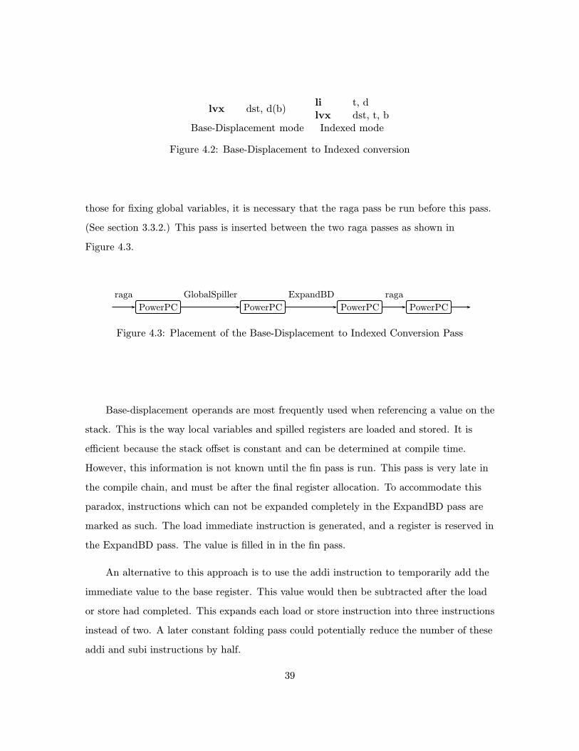
4.2 Base-Displacement to Indexed conversion . . . . . . . . . . . . . . . . . . . 39
4.3 Placement of the Base-Displacement to Indexed Conversion Pass . . . . . . 39
4.4 General Solution to Unaligned Data . . . . . . . . . . . . . . . . . . . . . . 41
4.5 General Vector Load and Store . . . . . . . . . . . . . . . . . . . . . . . . . 42
4.6 Special Case Solution to Unaligned Memory Accesses . . . . . . . . . . . . . 44
7

8
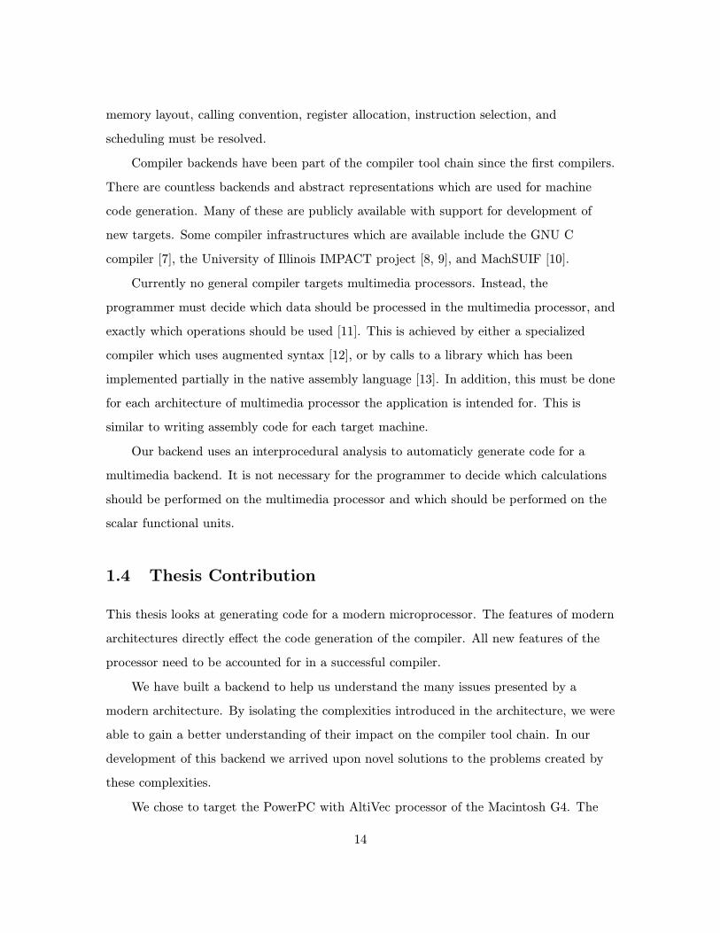
List of Tables
3.1 Common PowerPC instructions . . . . . . . . . . . . . . . . . . . . . . . . . 24
3.2 Scalar Code Generation Results . . . . . . . . . . . . . . . . . . . . . . . . . 33
4.1 Vector Datatypes . . . . . . . . . . . . . . . . . . . . . . . . . . . . . . . . . 36
4.2 Vector Load and Store Timing . . . . . . . . . . . . . . . . . . . . . . . . . 43
9

10

Chapter 1
Introduction
Advances in modern computer architecture have introduced numerous features that make
modern processors quite complex. Thus, generating code for these new processors is
becoming more difficult as well. Compilers can take advantage of these advanced features
to improve performance of the programs they compile. In this thesis we analyze the
impact of modern computer architectures on the compiler tool chain.
1.1 Modern Architectures
The computational power of a microprocessor has been doubling every 18 months since its
conception. Many factors contribute to the increases in speed. Faster electronics, smaller
transistors, increased die size, and improved designs. With new architecture designs come
more advanced, complex features. These features include dedicated functional units,
advanced instruction sets, specialized hardware for conditional branches, and dedicated
scheduling hardware.
The new features, while providing increased performance, require changes to the
compiler tool chain. These features are sometimes presented as modifications to the
instruction set architecture (ISA) directly exposed to the compiler, or as hardware
changes which do not effect the ISA. In either case, the compile tool chain is affected.
When a new hardware feature is not exposed to the compiler through the ISA, it is
11

still advantageous to take it into account when generating code. Taking the feature into
account can improve performance on certain hardware. Generating better code with this
consideration in mind is a violation of the abstraction provided by the ISA. The new code,
however, may run faster on the desired platform, which is the goal of any good compiler.
A typical example of a modern architectural feature hidden by the ISA is found in
super-scalar processors. Super-scalar processors execute multiple instructions
simultaneously on separate functional units [1]. The processor reschedules the instructions
as they are fetched making faster execution possible. Though this feature is hidden by the
ISA, it is still important for compilers to exploit it.
When an ISA exposes new features of the processor to the compiler, it allows the
compiler more options for optimization. New features may make code generation more
difficult, but allow more efficient code.
A good example of exposing a feature through the ISA is the use of single instruction
multiple data (SIMD) instructions. SIMD processors apply a single operation to multiple
pieces of data in parallel. This operation is prevalent in multimedia calculations. SIMD
processors are usually programmed with instructions tailored specificly to the processor.
These SIMD instructions are usually the basis of the instruction set of multimedia
processors.
Another example is the MIT RAW processor [2, 3] which exposes significantly more of
its feature set through the ISA than is typical. The resulting complexity from this
increased exposure makes creating an effective compiler for the RAW chip challenging.
However, by exposing more of the features to the compiler, the compiler has more control
over the execution and can improve program performance.
Conditional branches provide an example of new hardware features which are exposed
to varying degrees by the ISA. This is because of the work in reducing the cost of
conditional branches [4]. Branch prediction and instruction predication are the features
which reduce this cost. In branch prediction, the compiler predicts the direction of the
branch through some static analysis. Some processors revise this prediction based on
information collected during execution. This prediction is used to speculatively execute
12

the branch. Predication allows for conditional execution without a branch. If a branch
skips only a small number of instructions it may be better to not use a branch instruction.
Instead, the instructions are read, and committed only if the predicate is satisfied. Unlike
branch prediction, predicated instructions are generated by a compiler and not modified
by the processor.
1.2 Multimedia Processors
Popularity of multimedia applications has driven the development of special architectures
designed to perform multimedia calculations more efficiently. Multimedia calculations
typically involve performing the same operation to several different values simultaneously.
The processor that performs these calculations is called a super word unit or multimedia
processor, and is separate from the floating point unit (FPU) or central processing unit
(CPU).
To achieve modularity, the communication between the CPU and the multimedia unit
is limited. Typically, these units must communicate through memory. This limitation
reduces the effectiveness of the multimedia unit to directly aid in computations performed
on the CPU. However, a technique which some researchers call superword level parallelism
(SLP) has been shown to successfully achieve this [5, 6].
Multimedia processors use a SIMD ISA. This presents the new functionality directly
to the compiler.
1.3 Compiler Backends
A compiler can often be divided into two parts: a front end, which takes a program in a
particular language and produces a system-independent representation of the program; a
backend, which takes the system-independent representation of the program translates it
into a system-dependent representation, and generates assembly code for the processor.
Converting the system-independent representation into a system-dependent one involves
realizing many features which are intended to be hidden from the end user. Issues such as
13
memory layout, calling convention, register allocation, instruction selection, and
scheduling must be resolved.
Compiler backends have been part of the compiler tool chain since the first compilers.
There are countless backends and abstract representations which are used for machine
code generation. Many of these are publicly available with support for development of
new targets. Some compiler infrastructures which are available include the GNU C
compiler [7], the University of Illinois IMPACT project [8, 9], and MachSUIF [10].
Currently no general compiler targets multimedia processors. Instead, the
programmer must decide which data should be processed in the multimedia processor, and
exactly which operations should be used [11]. This is achieved by either a specialized
compiler which uses augmented syntax [12], or by calls to a library which has been
implemented partially in the native assembly language [13]. In addition, this must be done
for each architecture of multimedia processor the application is intended for. This is
similar to writing assembly code for each target machine.
Our backend uses an interprocedural analysis to automaticly generate code for a
multimedia backend. It is not necessary for the programmer to decide which calculations
should be performed on the multimedia processor and which should be performed on the
scalar functional units.
1.4 Thesis Contribution
This thesis looks at generating code for a modern microprocessor. The features of modern
architectures directly effect the code generation of the compiler. All new features of the
processor need to be accounted for in a successful compiler.
We have built a backend to help us understand the many issues presented by a
modern architecture. By isolating the complexities introduced in the architecture, we were
able to gain a better understanding of their impact on the compiler tool chain. In our
development of this backend we arrived upon novel solutions to the problems created by
these complexities.
We chose to target the PowerPC with AltiVec processor of the Macintosh G4. The
14

PowerPC is a reduced instruction set computer (RISC) with some modern complexities.
The AltiVec is a multimedia processor extension with a SIMD instruction set. This
provides several features which are reflected in a range of ways in the combined
instruction set architecture (ISA).
Developing this backend gave us a stronger understanding of the requirements which
a modern architecture places on the compiler backend.
15

16

Chapter 2
Supporting Infrastructure
Our backend implementation builds on work done by several sources. The compiler
infrastructure is based on SUIF2 [14] created by the Stanford SUIF group. The backend
infrastructure is based on MachSUIF2 [10, 15, 16] from the Harvard MachSUIF group.
Analysis for generating AltiVec instruction sequences is superword level parallelism
(SLP) [6] done at MIT.
2.1 SUIF
SUIF, Stanford University intermediate form, is the compiler infrastructure we used in
this project. SUIF2 is a later version of SUIF. They provide similar functionality, but use
different intermediate forms. We use SUIF2 in our backend implementation.
SUIF was designed to be a very functional infrastructure for developing compilers and
compiler algorithms. It provides significant support for program analysis, but is lacks
flexibility in program representation. SUIF2 was designed to provide additional flexibility
to the infrastructure. The intermediate form can be augmented relatively easily.
SUIF2 provides all the necessary infrastructure of a compiler front end. SUIF2 is used
by many universities for development of compiler algorithms. This is focuses on front end
compiler development and program analysis. For example, extensions to support C++
and Java are in progress.
17

SUIF2 provides a large set of libraries [17, 18] to operate on its intermediate form.
This includes iterators which apply operations to specific kinds of elements. It also
provides a driver engine to run and load compiled passes.
2.2 MachSUIF2
Significant variation between platforms, limits how much a backend infrastructure can
provide. MachSUIF2 is designed to make it easy to implement a backend for a RISC
architecture. Figure 2.1 shows the intended compile chain to convert a program in SUIF2
form into target specific assembler.
lower s2m genLowered SUIF2 SUIF VM Target Code
raga fin m2aTarget Code Target Code Target Assembly
Figure 2.1: Ideal MachSUIF2 compile chainThis is the ideal MachSUIF2 compile chain. This is the minimum set ofpasses necessary to translate SUIF2 into target specific assembly.
The lower pass flattens the intermediate form into structures which are very close to
those found in assembly language. The m2a pass translates this lowered form into
SUIFVM instructions. This is a virtual machine instruction set which is RISC like. These
instructions are then translated by a target specific gen pass into opcodes appropriate for
the desired target. The raga pass is a generic register allocator which works for practically
any architecture. The fin pass is a target specific pass which finishes up necessary calling
convention requirements. Finally, the m2a pass is a target specific pass which prints the
instructions to assembly code.
A large part of the work of a backend is done in the m2a and raga passes which do
the lowering and register allocating. These are both generic passes, which are provided as
part of the MachSUIF2 infrastructure.
The largest two of the remaining three passes is gen, which is mostly a simple
18

translations for RISC architectures, and fin which mostly involves creating header and
footer code for functions.
2.3 SLPCC
SLPCC utilizes the SUIF infrastructure and performs SLP analysis. SLPCC adds its
vector information to the program using SUIF annotations. These are a generic way of
augmenting the intermediate form. When converting from SUIF to SUIF2, it was
necessary to augment the conversion utility provided with SUIF2 to support the new
annotations.
The SLP analysis performs loop unrolling and reorders instructions to enhance
vectorization. It assumes that all arrays are aligned on boundaries equal to the vector size
of the target platform. With this assumption it finds vectorization which does not require
accessing unaligned memory addresses. However, if this restriction were relaxed, and
unaligned memory accesses were allowed, more vectorization could be found.
19

20

Chapter 3
Scalar Code Generation
This chapter introduces the PowerPC instruction set, and details some of the modern
architecture issues which are encountered in implementing a backend for this architecture.
The compile chain used in our implementation is presented with our solutions to the
problems encountered.
3.1 Compile chain
sf2c cpp snootFortran Source C Source Preprocessed C SUIF
slpcc convertsuif1to2 ppcvectorized SUIF SUIF2 PPC Assembler
Figure 3.1: Compile Chain OverviewThis is an overview of the compiler compile chain used in this project. Eachbox shows a form of the program. Arrow are labeled with the name of thepass which transforms the program from one form to another.
In our implementation both C and Fortran sources can be compiled into PowerPC
assembly code. Figure 3.1 illustrates the compile chain used in this project. When
compiling C source code, the Fortran form and f2c transformation are skipped.
21

The sf2c pass is part of the SUIF distribution. It translates Fortran source into C
code. The sf2c pass creates C code which uses some shared libraries for certain Fortran
functions. The API to these libraries is shared by all supported platforms. This makes it
possible to generate the C code independent from the target platform.
To precompile the C code, cpp from the GNU C distribution1 is used. The cpp pass
merges the C code with header files and other include files. It is critical that cpp use the
include files from the target platform because these include files have platform specific
data structures which will be used in the final result. This makes it necessary to
precompile on the target platform instead of our main SUIF development platform.
Another SUIF pass, snoot, is used to convert the preprocessed C code into SUIF.
This is the form which the vectorization analysis works on.
The slpcc pass is used to analyze the program for vectorization. This pass may also
perform loop unrolling and other transformations to improve the program’s vectorization.
This pass is skipped when generating PowerPC code without AltiVec optimizations. This
pass was developed on an x86 Linux platform, so the analysis is run there. Because SUIF
is a platform independent representation, this causes no platform related problems.
MachSUIF2 and our PowerPC code generation pass, ppc, is used to generate the
PowerPC assembly code. The ppc pass is broken down in more detail in Figure 3.2. The
rational behind each of these stages is described in later sections. Compare this
illustration to the ideal MachSUIF2 compile chain in Figure 2.1.
3.2 PowerPC Instruction Set Architecture
The PowerPC ISA is generally RISC like. As with most RISC architectures, arithmetic
operations operate on values in the register file, and not on values in memory. Explicit
store and load instructions are used to write and read values to and from memory.
Unlike more simple architectures, the PowerPC has a special set of condition registers
which it uses to decide the direction of a conditional branch. This leads to complications
1Version 2.95.2
22

lower s2m genLowered SUIF2 SUIF VM PowerPC
raga GlobalSpiller ragaPowerPC PowerPC PowerPC
fin GenerateDisplacementPowerPC PowerPC
LargeDispFixer LongJump m2aPowerPC PowerPC
Figure 3.2: PowerPC compile chain detailThis is an overview of the PowerPC code backend compile chain used in thisproject. Each box shows a form of the program. Arrow are labeled with thename of the pass which transforms the program from one form to another.This takes the place of the ppc arrow in Figure 3.1.
in code generation for some simple conditional statements.
Table 3.1 is a list of common PowerPC instructions and their semantics. The
assembly instructions used in this document do not use the same syntax as those which
are parsed by most assemblers. Instead, the instructions have been simplified for ease of
reading. This includes a shorthand notation in the conditional branch (bc) instructions,
and use of symbols in leu of registers.
For conditional branches, the value of BO may be either T indicating the branch is
taken if the corresponding bit is set, or F indicating the branch is taken if the
corresponding bit it not set. The offset o added to a condition register to select a
condition bit may have the values LT, GT, EQ, or NE indicating greater than, less than,
equal to, and not equal to respectively.
Most instructions operate on registers, and not variable symbols. Variable symbols
used in these assembly instructions indicate a register which has been allocated for that
variable. It is assumed that it is possible to allocate such a register.
23

Table 3.1: Common PowerPC instructionsMnemonic Simplified Semantics
btarget PC ← PC+target
bc BO, crn+ o, target PC ← PC+target if (CR[4n + o]=BO)
mr dst, src R[dst] ← R[src]
op dst, src1, src2 R[dst] ← R[src1] op R[src2]
cmp crn, src1, src2 CR[4n::4n+ 3] ← CMP(R[src1], R[src2]
cmpi crn, src, m CR[4n::4n+ 3] ← CMP(R[src], m]
li dst, n R[dst] ← n
lis dst, n R[dst] ← n× 232
ltype dst, offset(base) R[dst] ← MEM[offset+R[base]]
ltypex dst, base, offset R[dst] ← MEM[R[offset]+R[base]]
sttype src, offset(base) MEM[offset+R[base]] ← R[dst]
sttypex dst, base, offset MEM[R[offset]+R[base]] ← R[dst]
sttypeu src, offset(base) R[base] ← offset+R[base] ; MEM[R[base]] ← R[dst]
sttypeux dst, base, offset R[base] ← R[offset] + R[base] ; MEM[R[base]] ← R[src]
These are common PowerPC instructions. Some simplifications have beenmade to the actual semantics of these instructions.
3.2.1 Condition Registers
The PowerPC has an additional bank of registers which are used as the condition for
conditional branches. There are 8 of these 4 bit condition registers. This bank of registers
is denoted as the bit vector CR in Table 3.1.
In the code produced in this project, it is not necessary to use more than one of these
condition registers at a time. Because of this, the condition registers are allocated staticly
by the code generator, and not left for raga to allocate.
Condition register 6 has a special purpose. It is set to true when making a call to a
variable argument function which takes floating point parameters. It is set to false when
calling a variable argument function which does not use floating point arguments.
Unlike many RISC architectures, the PowerPC ISA stores four bits of information
about a compare. When a compare is performed a bit is set for each of: less than, greater
than, equal to, and not equal to. One of these bits is examined by the bc instruction to
decide if the branch is to be taken or not.
24

if (x > 0) &&(x < 10)
sgt c1, x, #0slt c2, x, #10and c3, c1, c2bne c3, fi
cmpi cr0, x, 0bc F, cr0+GT, ficmpi cr0, x, 10bc F, cr0+LT fi
sgt c1, x, #0bne c1, fislt c1, x, #10bne c1, fi
(a) (b) (c)
C code RISC assembly PowerPC assembly RISC assembly
Figure 3.3: Encoding a Simple If StatementThe C code is translated into RISC and PowerPC assembly sequences. RISCinstruction sequences (a) and (c) are written using the DLX instructionset[4]. The label fi immediately follows the body of the if.
This small difference results in significantly different optimal code generation because
the type of condition is decided at the branch and not at the compare. Figure 3.3 shows
how a if clause in C might be translated into RISC and PowerPC assembler. Assembly
sequence (a) is not general solution. The && operator in C is a short circuiting operator.
That is, if the left hand side evaluates to false, the right hand side is not evaluated.
Sequence (a) does not short circuit, while sequences (b) and (c) do. In this case, since
there are no side effects to the comparison, all three translations are semantically
equivalent and correct.
Because branches are typically relatively expensive instructions, sequence (a) may be
more efficient than the PowerPC instruction sequence (b). It is difficult to construct a
PowerPC instruction sequence which performs the same conditional branch with a single
branch. However, because the logical operators in C do short circuit, it is often not
desired to limit the number of branches. At this level, the distinction between the two
instruction sets is mostly superficial.
Another point to consider is the intermediate representation of conditional
statements. Typically, in languages like C, conditional expressions are exactly the same as
other boolean expressions. Furthermore, bitwise boolean logic is often interchangeable
with conditional boolean logic. Because most intermediate representations make the
assumption that boolean logic operating on conditions and other expressions are similar,
25

the distinction between the two often becomes unclear. To generate good code for the
PowerPC, it is necessary to make such a distinction.
Furthermore, MachSUIF2 generates RISC style conditional branches in its s2m pass.
The PowerPC gen pass then translates these instructions one by one. Because there is no
direct equivalence of a sge or bne instruction, these are each translated into several
instructions, each including a conditional branch. This comes at a significant performance
cost.
In order to perform this translation more efficiently, there are three alternatives. A
pass could be run before gen to mark all pairs of condition sets and conditional branches,
these could then be translated to the most efficient pair of PowerPC instructions in the
gen pass. Alternatively, the PowerPC gen pass could keep track of which instructions have
been generated and then backtrack if a more efficient sequence could be emitted. As a
final alternative, a pass could be run after the gen pass to clean up all of the extraneous
branches. This would have to do some dependency analysis to ensure that values
computed for the branches were not used elsewhere.
3.3 Target Operating System
Differences between operating systems effect the code the backend produces. We
considered LinuxPPC, AIX, and Macintosh OS9. Linux was chosen because it provided a
good development infrastructure, and the platform was readily available.
The differences between the operating systems is relatively small. Extending the
PowerPC Linux backend to support AIX or OS9 should be simple. The calling convention
and the global variable space differ between the OS’s.
The calling convention has significant differences between the operating systems. One
exception is the way mixtures of float and scalar parameters are passed. In AIX and OS9
integer argument registers are unused corresponding to each of the floating point registers
used. Under Linux, the first 8 floating point arguments are passed via registers, while still
allowing all the integer argument registers available for integer parameters. How
structured data types are passed also differs between the platforms.
26

The global data area also differs. In AIX a register is dedicated to point to the
beginning of the global data segment. This is typically constant throughout the execution
of the program. Under Linux, there is no such dedicated register. It would be possible to
dedicate a register to this purpose, but it would be necessary to maintain it for external
calls. Also, having a dedicated global base pointer limits the addressable global area to
32K bytes.
3.3.1 Structured Datatypes as arguments
0x00 Caller’s saved SP (SP and FP point here.)0x04 Saved return PC (or unused: i.e. if non-leaf)0x08 Space for extra parameters0x0C as many as needed for longest call0x10 from this function.0x140x28 Space for arguments (must start on a multiple of 0x08)0x2C up to 16 passed in registers0x30 8 int, 8 float, others0x34 placed into caller’s stack.0x38 Locals stored here0x3C as many as necessary.0x400x440x480x4C Caller’s FP0x50 Caller’s Frame (must start on a multiple of 0x10)
Figure 3.4: PowerPC Stack structure for Linux calling conventionThis is the stack structure used in the PowerPC calling convention on Linux.Space for arguments is optional (i.e. if the function makes no calls.) Param-eters are passed on the caller’s stack, so sufficient space for the call with thegreatest size of non-register parameters must be allocated.
Structured data types may be passed by value in C. Most calling conventions
accomplish this by passing the value of the structure on the stack or in registers as other
parameters are passed. That is, when an integer is passed by value, it value is placed on
the stack or in a register. The source is thus inaccessible from the callee. Structured data
27

.data .datax: .long 0 x: .long 0.text .textlis 3,x@ha lwz 3,x@l(gp)lwz 3,x@l(3)Loading a global on PowerPC Linux Loading a global on AIX
Figure 3.5: Loading a Value from the Data SegmentLoading a global variable on PowerPC Linux and PowerPC AIX. Becausethere is no global pointer (gp) in PowerPC Linux, it requires two instructionsto load a global variable instead of one.
types may be passed in a similar fashion.
The PowerPC calling convention differs slightly here. The structure is not copied into
the caller’s stack along with the other parameters. Instead it is copied elsewhere, usually
into the local variable area, and a pointer to the copy of the structure is passed instead.
This effectively changes the type of the parameter. To the caller, structures passed by
reference and those passed by value look exactly the same.
3.3.2 Global Variables
As noted in Section 3.3 Global variables are handled differently on PowerPC Linux than
on other platforms. To load a global variable, it is necessary to compute its complete
memory address, not just the offset from a frame, stack or global pointer. This is
accomplished with two instructions as shown in Figure 3.5.
More specifically, it requires two instructions to load values from the data segment.
Not all variables declared as global go into the data segment, and not all variables in the
text segment are declared global in the source code. For example, string literals are
usually placed in the data segment, and a global which is not used externally or globally
may (temporarily) be placed on the stack, in the heap, or in a register.
The example in Figure 3.5 uses register 3 for two purposes. It first loads part of the
address into register 3, then using the register as the base for the offset, loads into register
3. Using the same register for the base of the offset and the destination of the load works
28
in this case, but not in other cases. If the destination of the load is a floating point
register, the floating point register cannot be used temporarily to hold the base of the
address. Also, when storing into variables in the data segment, the register cannot be
recycled before the store takes place, so again we need to use an additional register. For
this reason, it is necessary that this pass run before register allocation.
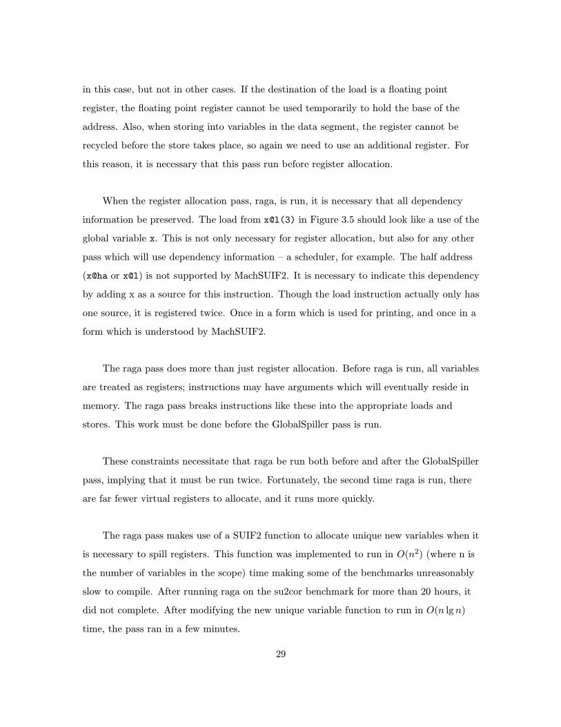
When the register allocation pass, raga, is run, it is necessary that all dependency
information be preserved. The load from x@l(3) in Figure 3.5 should look like a use of the
global variable x. This is not only necessary for register allocation, but also for any other
pass which will use dependency information – a scheduler, for example. The half address
(x@ha or x@l) is not supported by MachSUIF2. It is necessary to indicate this dependency
by adding x as a source for this instruction. Though the load instruction actually only has
one source, it is registered twice. Once in a form which is used for printing, and once in a
form which is understood by MachSUIF2.
The raga pass does more than just register allocation. Before raga is run, all variables
are treated as registers; instructions may have arguments which will eventually reside in
memory. The raga pass breaks instructions like these into the appropriate loads and
stores. This work must be done before the GlobalSpiller pass is run.
These constraints necessitate that raga be run both before and after the GlobalSpiller
pass, implying that it must be run twice. Fortunately, the second time raga is run, there
are far fewer virtual registers to allocate, and it runs more quickly.
The raga pass makes use of a SUIF2 function to allocate unique new variables when it
is necessary to spill registers. This function was implemented to run in O(n2) (where n is
the number of variables in the scope) time making some of the benchmarks unreasonably
slow to compile. After running raga on the su2cor benchmark for more than 20 hours, it
did not complete. After modifying the new unique variable function to run in O(n lg n)
time, the pass ran in a few minutes.
29

3.4 Large Immediate Values
The instruction word on the PowerPC is 32 bits. The load immediate instruction, li, takes
an immediate whose size is at most 16 bits. To load immediate greater than 16 bits in
size, it is necessary to break this into two instructions. This is similar to what is done
with global variables as discussed in Section 3.3.2.
Fortunately, in the case of loading immediates, there is no source variable which is
recycled as is the case with global variables. It is therefore possible to do this
transformation in the gen pass without needing to add any information for future passes.
Though translating large immediate values found in load immediate instructions can
be done in the gen pass, it does not cover all large immediate values. Large immediate
values may also be found in a base-displacement operand. Global variables are a special
case of a large immediate in a base-displacement operand where the base is zero.
For functions with very large stack displacements, large immediates may be found in
the statement which allocates space on the stack at the beginning of the function.
(Functions with large local arrays are common in the benchmarks addressed in this
project.) The stack size is not determined until the fin pass is run, so it is necessary for
this expansion pass to be run after fin.
Because all of these large immediate values can be handled in a single pass, they are
not expanded in the gen pass, but instead left until the end of code generation. This pass
is LargDispFixer in Figure 3.2.
3.5 Long Conditional Branches
The encoding of a conditional branch is offset based. That is, the immediate value
encoded in the instruction is the value which must be added to the PC to make the
branch. This immediate is a 16 bit value. This limits the conditional branch to jump at
most 32K bytes. Unconditional branches can jump to offsets of up to 227 = 128G bytes.
Many of the benchmarks examined in this project needed conditional branches to
span more than this distance. This is the case for many large loops.
30

bc BO, cr0+n, far
.
.
.
.
far:
bc BO, cr0+n, not far...b over
not far:b far
over:...
far:
bc BO, cr0+n, overb far
over:
.
.
.
.
far:
Initial code. Branch spansmore than 32K bytes. This in-struction cannot be coded inthe PowerPC ISA.
Modified code. Conditionalbranch targets an intermediateunconditional branch.
Alternate modified code. Con-ditional logic is reversed andtarget is reached by an uncon-ditional branch.
Figure 3.6: Distant Branch Target Solutions
There are two ways to utilize unconditional branches to increase the range of
conditional branches that were considered in this project. One way is to have the
conditional branch jump to an unconditional branch that jumps to the final destination.
Alternatively, the logic of the conditional branch could be reversed, and the target
changed to jump over an unconditional branch that jumps to the final destination. These
two options are illustrated in Figure 3.6
Both of these options increase the code size. Aside from the usual consequences (i.e.
increased instruction cache miss rate) this may also increase the distance which other
conditional branches need to jump. This may cause a chain reaction making it difficult to
do this transformation in a fixed number of passes.
Branching to an unconditional branch has the advantage that the logic of the
conditional branch is not changed. If some work were put into branch prediction and
control flow in previous passes, this would not be lost, and the program control flow would
31

be most similar to the original control flow.
Finding a place to put the unconditional branch may be difficult. From the example
in Figure 3.6 the distance from the conditional branch to label far is greater than 32K
bytes. The distance to label not far must be less than 32K bytes. Therefore, the not far
label must be between the two, in between other instructions of this function, or if the
conditional branch is less than 32K bytes from one end of the function, it may be placed
outside the function.
Placing the intermediate target inside the function requires one of two options. Find
a place in the control flow which can’t be reached. This would be following an existing
unconditional branch or return statement. This point would need to be within 32K bytes
of the unconditional branch. If such a point could not be found, a second option would
have to be employed. An additional unconditional branch around the new target would
have to be established as shown in Figure 3.6. This way the new target could be placed
anywhere. If the new target were placed inside a highly trafficked tight loop, there may be
some negative performance impact.
The algorithm for of the alternate approach is much simpler. The logic of the branch
is reversed so that the branch is taken in only the cases when it was not taken before.
This is encoded in the BO operand of the bc statement shown in figure 3.6. The target of
the branch is then changed to be the following instruction. Between the two is inserted an
unconditional branch to the initial target. Also encoded in the BO operand is a branch
prediction bit. This bit is flipped to preserve any branch prediction information.
The disadvantage of this transformation is that a branch must be taken whether the
condition is true or false. On most modern architectures the unconditional branch costs
very little. This is true for the G4 PowerPC which is the target of this project.
This transformation is performed in the LongJumpFixer pass. (See Figure 3.2.) It is
necessary that this pass be run near the end of the compile chain because it depends on
code size. Any pass which inserts or deletes instructions could potentially destroy the
work which this pass does.
In order to increase performance of this pass at compile time, some assumptions were
32

Table 3.2: Scalar Code Generation ResultsBenchmark ppc gcc -O1 gcc -O2 gcc -O3
tomcatv 9.78 7.66 7.30 7.30
swim 7.77 3.72 2.69 2.68
mgrid 39.86 18.62 12.48 12.47
made. First, it is assumed that all bc statements operate within a single function.
Branches to other functions should be done with a call (i.e. bl) statement. Second, it is
assumed that the instruction word size is 4 bytes and instructions are emitted in sequence,
without any unnecessary space between them. From these assumptions we can determine
the distance in bytes between any bc statement and its target.
This analysis and transformation is done in two passes. It operates on a single
function at a time. First the function is scanned and the byte offset to each label is
recorded. Next, the function is scanned for bc statements, and the distance between the
branch and its target is estimated. If it is greater than half the maximum allowed
distance, the transformation is applied.
Choosing to transform branches spanning more than half the maximum distance may
transform more branches than necessary. However, it guarantees that the pass can be
done in two scans of the code. Because each branch is expanded into two instructions, the
code size, and distance between branch and target, can at most double. Therefore
applying the transformation when half the limit is reached is safe.
3.6 Results
We successfully created a backend for PowerPC code generation. Using the Spec95 FP
benchmark suite we were able to compare our backend against code generated by gcc.
These results are shown in Table 3.2.
In the benchmarks we were able to successfully compile, our backend performs
significantly worse than gcc. This is due to a number of factors. A lack of data-flow and
other optimizations contribute to the increased execution times. The main contributing
33

factor is the inefficient translation of conditional branches. Not only are the set and branch
instructions translated inefficiently by the ppc pass, but s2m also expands conditional
branches significantly. The end result is that a branch which could be translated into two
instructions is instead translated into nearly 20 lines of code with up to 4 branches.
34

Chapter 4
Multimedia Vector Code
Generation
There are several issues which make multimedia code generation different than code
generation for other targets. Because the word size of the multimedia unit is larger than
the word size of the rest of the machine, alignment of data structures needs to be handled
carefully. The separation of the multimedia processor from the CPU complicates register
allocation. Also, additional optimizations which are unique to multimedia units may be
applied.
4.1 AltiVec Instruction Set Architecture
The AltiVec uses vector registers and a Single Instruction Multiple Data (SIMD)
instruction set. Each vector register is 128 bits wide. Table 4.1 shows the data types
permitted in a vector. Note that neither 64 bit floating point or integer operations are
supported on AltiVec. Vector instructions in the AltiVec unit are SIMD instructions.
They perform the same computation on every element of the vector.
35

Table 4.1: Vector Datatypes
Word Size Elements per Vector Floating point Integer
8 bits 16 no yes16 bits 8 no yes32 bits 4 yes yes
This table shows the vector types supported on the AltiVec unit.
Arithmetic Instructions
AltiVec arithmetic instructions perform one operation on all of the elements in a vector. A
vector add takes two source registers and one destination register. The sum of each
corresponding value is computed and placed into the destination vector.
Most arithmetic instructions come in two forms; these are saturate and modulo. A
vector add saturate will compute the sum, and if it exceeds the range of that type, the
resulting value will be the closest maximum value for that type. The vector add modulo
instruction operates the way most architectures implement add. Saturated instructions
only exist for integer types.
Permutation Instructions
Several instructions exist for the purposes of permuting and moving data between vectors.
The most general of these instructions is the vector permute instruction. One vector is
used to specify the desired permutation, the values from two other vectors are then
permuted into a destination vector. This instruction may be used to shift, rotate, or
otherwise permute each byte of the source vectors into the destination vector.
To support this general permutation instruction there are instructions which load
useful permutations specifications into a vector. For example, there is a vector load for
shift right instruction.
36

a
b
c
Figure 4.1: Alignment IllustratedEach square in this figure represents a word of memory. The gray squaresindicate an array using those words. These arrays are labeled for reference.The thicker black lines indicate 128 bit boundaries.
Load and Store Instructions
All load and store instructions use the indexed memory mode. This is the mode used by
the ltypex instructions in Table 3.1. The base-displacement memory mode is not
supported in the AltiVec ISA.
There are load and store instructions to store varying sizes of data. Individual bytes,
half words, or words can be stored as well as the complete 128 bit vector.
4.1.1 Alignment Restrictions
A word in the AltiVec unit is 128 bits. This is 4 times the word size of the CPU. This
allows 4 integer, or floating point calculations to be performed simultaneously in the
AltiVec unit. A super word register may be loaded from memory, or copied from another
super word register. To load a full super word from memory, it is most efficient to load
consecutive data aligned on a 128 bit boundary. Individual 8, 16, or 32 but words may be
loaded at roughly the same cost as a single 128 bit load. This results in an importance of
data alignment. The compiler may need to re-organize alignment and placement of
variables in a program to reduce the cost of loading them into the AltiVec unit.
Though a compiler may reorganize the alignment of some data, not all alignment
issues can be avoided this way. Some functions may be passed arrays or pointers to
37

memory of arbitrary alignment, making it impossible to determine the alignment of data
at compile time. Figure 4.1 shows three arrays stored in memory at different 128 bit
alignments. This makes it difficult to perform calculations between the arrays because the
data must be realigned in the AltiVec registers.
Because it is most efficient to write a 128 bit word to memory at a time, it is
sometimes necessary to perform a read before writing back to memory. This is the case
when writing to the beginning or end of an array which is not aligned on 128 bit
boundaries. It is necessary to preserve the values in memory before and after the array.
Writing a 128 bit word without reading the previous values first may destroy the values
which were there.
4.2 Implementation
In implementing code generation for the AltiVec unit, the most prevalent consideration we
came upon was memory alignment. It was also necessary to extend the backend to have a
consistent representation of the new vector types, and to accommodate some of the
limitations of the instruction set.
4.2.1 Load and Store instructions
There are two addressing modes which are used in the PowerPC instruction set. These are
the base-displacement, and indexed modes. See the ltype and ltypex instructions in Table
3.1 for examples of these modes.
The AltiVec instruction set only supports the indexed memory mode. Because the
backend and backend infrastructure assumes that the base-displacement mode is available,
it was necessary to create a pass which converts base-displacement memory accesses into
indexed mode accesses for the AltiVec instructions.
Figure 4.2 shows the transformation we used to convert memory references in the
base-displacement mode to indexed mode. This process requires using a new temporary
register, t, to hold the displacement value. Because this pass uses new registers, it must
run before the final register allocation pass. However, because of similar constraints to
38
lvx dst, d(b)li t, dlvx dst, t, b
Base-Displacement mode Indexed mode
Figure 4.2: Base-Displacement to Indexed conversion
those for fixing global variables, it is necessary that the raga pass be run before this pass.
(See section 3.3.2.) This pass is inserted between the two raga passes as shown in
Figure 4.3.
raga GlobalSpiller ExpandBD raga
PowerPC PowerPC PowerPC PowerPC
Figure 4.3: Placement of the Base-Displacement to Indexed Conversion Pass
Base-displacement operands are most frequently used when referencing a value on the
stack. This is the way local variables and spilled registers are loaded and stored. It is
efficient because the stack offset is constant and can be determined at compile time.
However, this information is not known until the fin pass is run. This pass is very late in
the compile chain, and must be after the final register allocation. To accommodate this
paradox, instructions which can not be expanded completely in the ExpandBD pass are
marked as such. The load immediate instruction is generated, and a register is reserved in
the ExpandBD pass. The value is filled in in the fin pass.
An alternative to this approach is to use the addi instruction to temporarily add the
immediate value to the base register. This value would then be subtracted after the load
or store had completed. This expands each load or store instruction into three instructions
instead of two. A later constant folding pass could potentially reduce the number of these
addi and subi instructions by half.
39

4.2.2 Loading and Storing Unaligned Data
The load and store instructions generated by the SLP analysis are guaranteed to be
aligned on 128 bit boundaries. This makes it easy to translate load and store instructions.
However, if this restriction were relaxed, and the SLP pass could take advantage of
unaligned data as well, more vectorization would be possible. To support this possibility
and furthermore, to make our backend more general, it is important to consider the case
where the previous analysis can not make such strong assertions about the alignment of
the data.
Often times the alignment of data can not be guaranteed. For example, a function
may dereference a pointer which is the result of an outside library call, and it may be
desirable to use a vector to load four words from this address. In this case, we may not be
able to guarantee anything about the alignment of the data at compile time.
Because loading and storing unaligned data is potentially a relatively common
operation, and tends to be very expensive, it was necessary to develop an efficient code
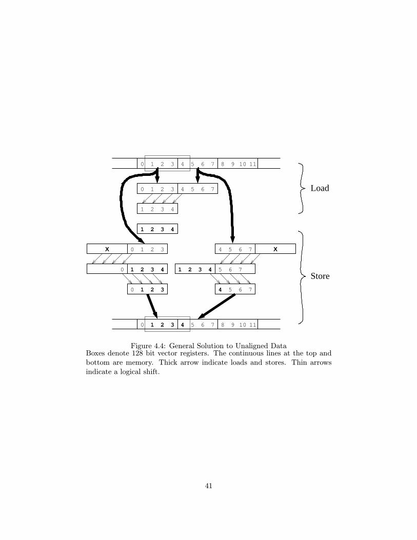
sequence for this operation. The general mechanism used in this project is shown in
Figure 4.4.
The example in Figure 4.4 shows loading 4 words of data into a vector register. This
can be generalized for any supported alignment and word size. Alignment is limited to a 1
byte resolution. Word sizes are irrelevant since the entire 128 bit word is loaded. The
generalized load code is shown in Figure 4.5. It contains an optional optimization for
loading data in the aligned case.
We considered an alternative to the load and store code presented here. One may
think that to use the store vector element instructions, it only takes 4 store word element
instructions to store the vector at an arbitrary alignment. Four store word instructions
will may execute more quickly than two vector loads and two vector stores. Unfortunately,
the vector store element instruction will only store elements which are the same alignment
in the vector as they are in memory.
On the AltiVec, the four store word instructions execute roughly twice as fast as the
two loads and two stores, but still not as fast as a one or two vector stores. Table 4.2
40
1 2 3 4
1 2 3 40
0 21 3
31 20
X
0 21 3 4 5 6 7
1 2 3 4
0 21 3 4 5 6 7 8 9 10 11
8 9 10 110 5 6 71 2 3 4
4 5 6 7
5 76
5 6 74
1 2 3 4
X
Store
Load
Figure 4.4: General Solution to Unaligned DataBoxes denote 128 bit vector registers. The continuous lines at the top andbottom are memory. Thick arrow indicate loads and stores. Thin arrowsindicate a logical shift.
41

ldvx vr3, offset, baseandi test, offset, 0x0Fcmpi cr0, test, 0bc cr0, EQ, overaddi offset2, offset, 16ldvx vr1, offset2, baseldvfsl vr2, offset, baseperm vr3, vr3, vr1, vr2
over:
andi test, offset, 0x0Fcmpi cr0, test, 0bc cr0, EQ, overldvx vr0, offset, baseaddi offset2, offset, 16ldvx vr1, offset2, baseldvfsl vr2, offset, baseperm vr4, vr0, vr0, vr2perm vr5, vr1, vr1, vr2ldvfsr vr8, offset, baseperm vr7, vr3, vr5, vr8perm vr3, vr4, vr3, vr8stvx vr7, offset2, base
over:stvx vr3, offset, base
Load MEM[R[offset]+R[base]] into vr3 Store vr3 into MEM[R[offset]+R[base]]
Figure 4.5: General Vector Load and StoreCode in italics may be left out. When the data is aligned, this code bypassesthe instructions required for unaligned data. The code is still correct withoutthis optimization.
42

Table 4.2: Vector Load and Store Timing
Instruction Alignments timing
lwz {0,4,8,12} 1.85lvx {0,16} 0.97lvx {0} 1.01
stw {0,4,8,12} 0.97lvx,stvx {0,16,16,0} 2.01lvx,stvx {0,16,0,16} 2.17stvx {0,16} 0.51stvx {0} 0.32
The timings shown in this table are based on load and store instructionsplaced in a tight loop ranging over a 40000 byte array. The instructionshown in the first column were executed at the alignments shown in thesecond column. One load or store at each of the listed alignments is executedper iteration. For rows with both load and store instructions listed, the twoloads are performed before the two stores.
shows these relationships. Also shown in this table is a comparison between the vector
and scalar load functions. This table shows that in the general load store case, it is most
efficient to load the data with
4.2.3 Additional Load Store Optimizations
The code presented in Figure 4.5, though completely general, is not very efficient. If the
data is unaligned, the combination of load and store operation takes 6 memory accesses,
plus additional instructions to load the data. When loading 32 bit words, the equivalent
operation on the CPU takes 8 memory accesses. This is a worst case comparison. Loading
smaller word sizes would take the same number of memory accesses on the AltiVec unit,
and a larger number of accesses for the CPU.
Though this generated code for the AltiVec outperforms the equivalent instructions
on the PowerPC, there are significant improvements which can be made. The ideal ratio
of 2 memory accesses per load and store can be achieved.
Vector load and store operations often occur inside a loop body which steps through
an array of continuous memory. It is in this special case which we are able to achieve an
43

1 2 3 4
1 2 3 40
0 21 3
31 20
X
0 21 3 4 5 6 7
1 2 3 4
0 21 3 4 5 6 7 8 9 10 11
8 9 10 110 5 6 71 2 3 4
4 5 6 7
5 76
5 6 74
1 2 3 4
X
Figure 4.6: Special Case Solution to Unaligned Memory AccessesBoxes denote 128 bit vector registers. The continuous lines at the top andbottom are memory. Thick arrow indicate loads and stores. Thin arrowsindicate a logical shift. Medium arrows indicate a move within a register.Dashed lines indicate a carryover from one iteration to the next.
amortized ratio of 2 memory accesses per general load and store. Figure 4.6 illustrates our
algorithm to achieve the amortized rate of 2 memory accesses per general load and store.
In figure 4.4 we see that the same memory is loaded twice before the generalized load
and store are completed. By storing these values in registers for the duration of the
modifications to the desired data, we can eliminate the redundant load.
In the subsequent iteration of the loop, we only need to load one of the two vectors
from memory. The other we already have from the previous iteration. Similarly, one of the
stores from the previous iteration may be postponed to this iteration provided that we use
the vector’s value instead of the unmodified copy from memory.
44

4.2.4 SLP Analysis
The AltiVec instruction set does not provide an instruction to move data directly from the
CPU’s registers into the multimedia vector registers. Data must be transfered through
memory. Because memory accesses are typically the slowest operations on modern
computers, executing a computation partially on each unit is expensive. It is critical to
determine on which unit the computation should take place.
The SLP analysis finds and vectorizes statements which can be performed on the
AltiVec unit. It takes the cost of loading and storing the data into account in this
analysis. This attempts to minimize the communication between the two processors. The
cost model used in the SLP analysis assumes that vector loads and stores are actually only
a single load and store, not the six loads and stores in our general case. Thus it is
important to reduce the number of loads and stores so that the SLP analysis does not
hinder the performance of the code.
4.3 Results
We were unable to complete the backend AltiVec code generation, but we were still able
to discover many issues raised by targeting this architecture. We found that data
alignment is of critical importance to achieve high performance SIMD execution. However,
even with a minimal SLP analysis the SIMD unit can be used beneficially.
45

46

Chapter 5
Conclusion
In our development of a backend for a modern architecture, we discovered many impacts
of the new architecture on the compiler tool chain. The new features added to the
architecture add not only complexity to the processor design, but also to the backend
development making implementation harder. We found three major impacts of the G4
PowerPC and Altivec processors on the compiler backend. Use of dedicated condition
registers resulted in suboptimal code generation. Limited instruction word length (and
instruction set) increased compiler complexity and impacted compiler performance.
Limited memory functionality of the multimedia unit significantly impacted vector
memory accesses.
Condition registers are a modern architecture feature which can improve performance
of conditional branches. This modification to the ISA may seem superficial, but it
introduces complexities to the backend. Modern compiler tool chains use an infrastructure
which is designed to target a standard RISC architecture. The PowerPC’s condition
registers are not a standard RISC feature. This makes it difficult to generate good
conditional branch code with a standard backend infrastructure. Furthermore, languages
like C, encourage a representation which computes boolean values before a decision to
branch is made. Because the choice of comparison is delayed until the branch instruction
in the PowerPC ISA, it is necessary to perform either significant analysis or
transformation to produce good code.
47

The AltiVec’s SIMD instructions have potential to significantly increase performance.
However, the memory access functions of the AltiVec serve as a serious detriment resulting
in compiler backend complexity and poor code generation. Because only aligned stores are
supported, the cost of a single vector store quadruples when the alignment is unknown.
With a significant amount of analysis, in special conditions, this can be reduced to the
ideal cost of a single store per unaligned vector store. The limited address modes
supported by the AltiVec also hinder code production.
These features and intricacies of a modern architecture show the critical impact of
architecture on the compiler tool chain. Features directly exposed like the SIMD
instructions of the AltiVec unit, and minor ISA changes like the conditional branches
impact code generation. Hidden features like super-scalar scheduling and memory timing
need to be considered in the code generation. From our development of a backend for the
G4 PowerPC and AltiVec we demonstrated the impact of a modern architecture on the
compiler tool chain.
5.1 Future Work
There are several components of the backend infrastructure which are incomplete and
would be necessary to make this backend generally useful. These limitations did not stop
us from analyzing the many issues of modern backend development.
Currently there is only limited support for variable argument function calls. The
backend correctly generates code for calls to variable argument functions, but is not able
to compile functions which take a variable number of arguments. The compilation of such
functions has been sketched out, but its implementation is still incomplete.
48

Bibliography
[1] R. M. Tomasulo, “An efficient algorithm for exploiting multiple arithmetic units,”IBM J. Research and Development 11:1 (January), 25-33, 1967.
[2] Elliot Waingold, Michael Taylor, Devabhaktuni Srikrishna, Vivek Sarkar, Walter Lee,Victor Lee, Jang Kim, Matthew Frank, Peter Finch, Rajeev Barua, Jonathan Babb,Saman Amarasinghe, and Anant Agarwal. “Baring it all to Software: Raw Machines,”IEEE Computer 30(9), September 1997.
[3] Anant Agarwal, Saman Amarasinghe, Rajeev Barua, Matthew Frank, Walter Lee,Vivek Sarkar, Devabhaktuni Srikrishna, and Michael Taylor. “The Raw CompilerProject,” Proceedings of the Second SUIF Compiler Workshop, Stanford, CA, August21-23, 1997.
[4] John L. Hennessy and David A. Patterson. Computer Architecture: A QuantitativeApproach. Second Edition Morgan Kaufmann Publishers, Inc., 1996
[5] Samuel Larsen, “Exploiting Superword Level Parallelism with Multimedia InstructionSets,” Proceedings of the ACM SIGPLAN ’00 Conference on Programming LanguageDesign and Implementation (PLDI) 145-156, 2000.
[6] Samuel Larsen, “Exploiting Superword Level Parallelism with Multimedia InstructionSets,” MIT 2000 Master of Science Thesis, 2000.
[7] Free Software Foundation. “Simpler Porting”http://gcc.gnu.org/projects/#simpler porting, 2001.
[8] Benjamin T. Sander, “Performance Optimization and Evaluation for the IMPACT x86Compiler,” MS thesis, Department of Computer Science, University of Illinois, UrbanaIL, May 1995.
[9] Roland G. Ouellette, “Compiler Support for Sparc Architecture Processors,” MSthesis, Department of Computer Science, University of Illinois, Urbana IL, May 1995.
[10] Michael D. Smith, “/home/mds/research/machsuif”http://www.eecs.harvard.edu/hube/research/machsuif.html, Harvard University,1999.
49

[11] Steve Paavola, “Altivec for Real Time Multiprocessor Implementations,”http://www.altivec.org/articles/real time.cfm
[12] Motorola. Altivec Technology Programming Interface Manual, November 1999.
[13] Motorola. Altivec Technology Programming Environments Manual, November 1998.
[14] “SUIF2” http://suif.stanford.edu/suif/suif2/
[15] Michael D. Smith and Glenn Holloway, An Introduction to Machine SUIF and ItsPortable Libraries for Analysis and Optimization, Harvard University.
[16] Michael D. Smith, “Extending SUIF for Machine-dependent Optimizations,”Proceedings of the First SUIF Compiler Workshop, Stanford, CA, pp. 14-25, January1996.
[17] Gerald Aigner, Amer Diwan, David L. Heine, Monica S. Lam, David L. Moore, BrianR. Murphy, Constantine Sapuntzakis, “SUIF Compiler System - The Basic SUIFProgramming Guide.” Computer Systems Laboratory, Stanford University, 1999.
[18] “The SUIF Interfaces Guide”http://suif.stanford.edu/suif/suif2/doc-2.2.0-4/interfaces-guide.html
[19] “Code Warrior for MacOS - New Features”http://www.metrowerks.com/desktop/mac os/extra2, Metrowerks, 1995-2000
[20] Derek J. DeVries, “A Vectorizing SUIF Compiler: Implementation and Performance.”Master’s thesis, University of Toronto, June 1997.
50