Design and Implementation of a Link Level Adaptive ... and Implementation of a Link Level Adaptive...
38
Design and Implementation of a Link Level Adaptive Software Radio Richard A. Killoy May 27, 1999 Information & Telecommunication Technology Center
Transcript of Design and Implementation of a Link Level Adaptive ... and Implementation of a Link Level Adaptive...

Design and Implementationof a
Link Level Adaptive Software Radio
Richard A. KilloyMay 27, 1999
Information & TelecommunicationTechnology Center

3UHVHQWDWLRQ�2YHUYLHZ
• Brief Overview of RDRN
• Motivation - Why build this radio?
• Transceiver System Level Description
• Transmit and Receive ChainImplementation
• Summary & Future Work

RDRN Overview
• Design High-Speedwireless ATM/IPComm. Systems withNetwork and DLLadaptability which arerapidly deployable.
• Sponsored byDARPA’s GLO-MOinitiative
This years goals:
• Channel Estimation &Link Adaptation
• Software Radios
• Adaptive Networking
• Resource ReservationStyles
• ComparativePerformance Evaluationof IP vs. ATM
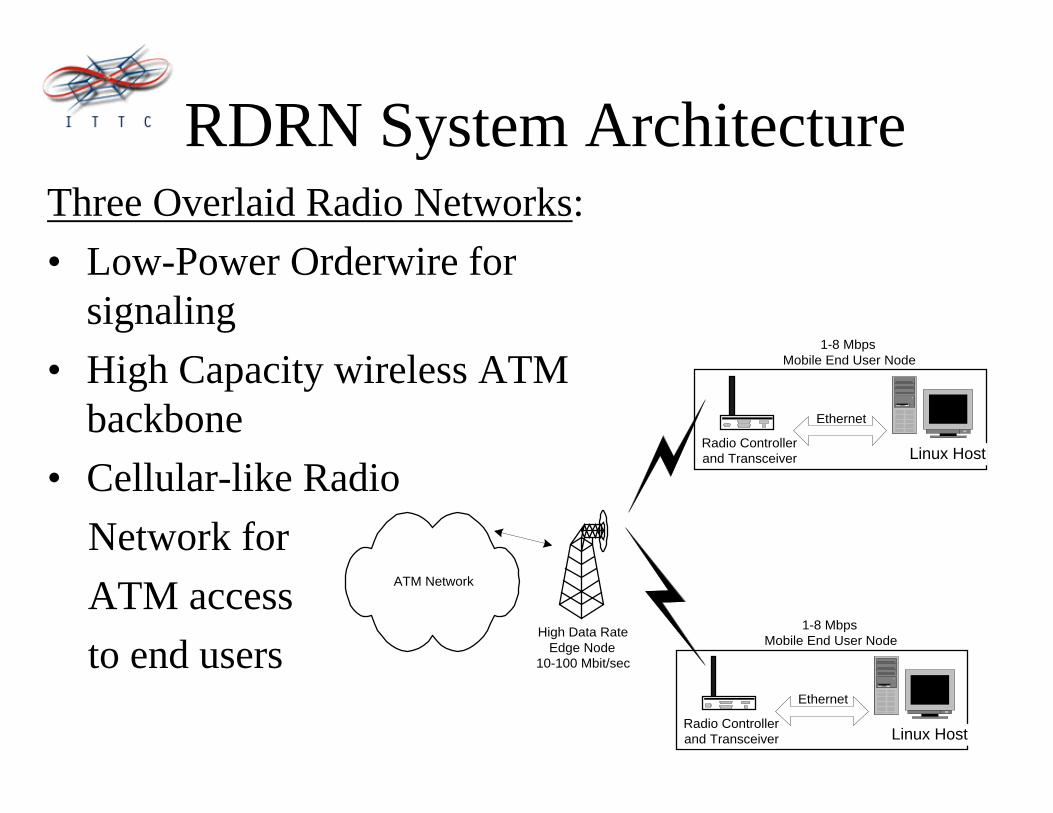
RDRN System ArchitectureThree Overlaid Radio Networks:
• Low-Power Orderwire forsignaling
• High Capacity wireless ATMbackbone
• Cellular-like Radio
Network for
ATM access
to end users
Linux Host
Ethernet
Radio Controllerand Transceiver
1-8 MbpsMobile End User Node
ATM Network
High Data RateEdge Node
10-100 Mbit/sec
Linux Host
Ethernet
Radio Controllerand Transceiver
1-8 MbpsMobile End User Node

0RWLYDWLRQGoal Solution Strategy Employed
Channel Estimation Algorithms The use of adaptive equalization,
functioning as channel estimators.
Link Level Adaptation Algorithms Software radio allows us the flexibility to
change link level parameters.
Radios to Test, Evaluate, and Validate
the channel estimation and link-level
algorithms
Software radios implementing the use of
high-speed ADC and various DSP chips.
These chips can be programmed
dynamically via a PowerPC processor.
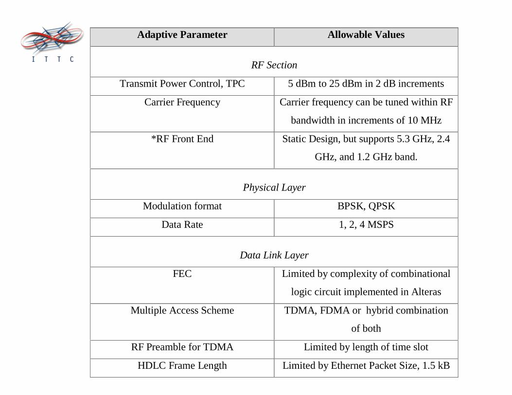
Adaptive Parameter Allowable Values
RF Section
Transmit Power Control, TPC 5 dBm to 25 dBm in 2 dB increments
Carrier Frequency Carrier frequency can be tuned within RF
bandwidth in increments of 10 MHz
*RF Front End Static Design, but supports 5.3 GHz, 2.4
GHz, and 1.2 GHz band.
Physical Layer
Modulation format BPSK, QPSK
Data Rate 1, 2, 4 MSPS
Data Link Layer
FEC Limited by complexity of combinational
logic circuit implemented in Alteras
Multiple Access Scheme TDMA, FDMA or hybrid combination
of both
RF Preamble for TDMA Limited by length of time slot
HDLC Frame Length Limited by Ethernet Packet Size, 1.5 kB

Antenna PortsTx IF/RF InterConn.
Rx IF/RFInterconnects
RF Front End
PowerPCMicroprocessor
Board
Main DigitalBoard
BERTPorts
Complete System Including Housing

Transmitter Requirements
• Transmit within RF bands at 5.3 GHz, 2.4 GHz, and 1.2 GHz
• Frequency Agility – ability to select from multiple channels within each RF band
• Average power output of +30 dBm (1W) from each antenna
• RF Bandwidth = 100 MHz
• Channel BW = 10 MHz
• Selectable QPSK or BPSK modulation
• Symbol Rates of 1, 2, or 4 Msymbols/sec
• Multiple Access: FDD with TDMA/FDMA
• Transmit Power Control ( 2 dB steps from 5 dBm to 25 dBm)
• Transmit Power ON/OFF capability (TDMA)
• TxData received from PowerPC
• LO Spurious level = -28 dBm
• LO Phase Noise <= -130 dBc/Hz at 50 MHZ offset

LinuxHost
5.3 GHz Quad-SectoredAntenna
Software Selectable,Sectored Beamforming
RFIFDigital
FormattingPowerPC
Ethernet
240 MHz 5.06 GHzSoftware Control of
Initialization, TransmitPower and
Beamforming
Beamforming Control
Transmit Power Control
Transmitter System Level Diagram

4 TX Channels 4 RX Channels
5.35 GHz5.25 GHz
5.3 GHz
1 Channel = 10 MHz
a bc d ab c d
10 MHz
RF Band = 100 MHz
5 MHz
50 MHz
Spectrum Utilization

Receiver Requirements
• Receive within RF bands at 5.3 GHz, 2.4 GHz and 1.2 GHz
• Frequency Agility – ability to select from four channels within RF band
• Full Duplex Operation
• Digital IF Architecture (subsampling)
• Demodulate QPSK or BPSK modulation
• Receiver band selectivity = 100 MHz
• Receiver channel selectivity = 10 MHz
• Symbol Rates from 1, 2 or 4 MSymbols/sec
• Dynamically configurable – must be a multidimensional radio with varying
software profiles (Software Radio)
• RxData passed to PowerPC
• NFmax <= 10 dB
• Receiver sensitivity = -85 dBm
• Dynamic Range = 60 dB

RF
PatchAntenna
5.23 GHz
IF Digital Radio PowerPCLinuxHost
ADC DQT DCL
store recovered symbols for channelestimation
AGC Control
Adaptivity, Programmingand Initialization
Ethernet
Receiver System Level Diagram

Benefits to Digital Demodulation• No need for tuning filters
• Can Construct Linear Phase Filters
• Flexible BW selection
• Multiple Modulation Formats can besupported
• System can be simulated “exactly”
• Multiple Radio “Personalities” as easy assetting up tables

PowerPCDigital
FormattingIF RF
I2C[0..4] - for programmingPLL’s
A[0..2]D[0..6]
Add&Data Bus fordemodulator programming
4
10 5
ì PLL programmingì Programmable Attenuatorsì Beamforming
Control Bus is a serial bus controlling:
5
5
BF[0..4]
ATTEN[0..4]EX[0..3]
Data DigitalData
AnalogTxSignal
Control Bus Architecture

Bit Error Rate (BERT) Ports
Power Section+12 È +9, +5, +3.3V
Tx IF Stage
240 MHz PLL & VCO
10MHzOscillator Rx IF Stage
AGC Amp
IF TestPoint
ADC,fs=40MSPS
40MHz CLK &CLK Drvr
BusControlAltera
Tx SourceSelect
(PPC, PN, BERT)AGC Power Level
Indicators
ProgrammableDQT and DCL

Rx Ant.Port
IF Input
Tx Ant.Port
IF Output10 MHz Ref.
Input
VCO’sPLL’s
5.3 GHz Modular RF Front End

Average Power Requirements
Voltage [V] Current [A] Power Needed[W]
Regulators (alone) 12 40m 0.480Analog Sections 12 120m 1.44
9V sections 12 190m 2.28Total for Analog Sections 12 350m 4.2
5V Digital.(Quiescent Only)
5V 1.6 8
3.3V Digital. Powering onlyAltera’s (Quiescent Only)
3V 333m 1
Total Power for Digital 9 W
Total Power PPC (Quiescent),datasheet claims 8W
5 W
Total Power 12 V 1.52 A 18.2 W

Receiver Implementation
+8dB +20dB
LO
5.23 GHz LOPLL & VCO
5.3GHzOmni
Antenna
MGA82563
HMC218MS8
LPF MSA0611
Patch hasselectivity of
130 MHz BW
NF=2.5dBP1dB=+17dBmIIP3=+31dBm
Dbl Balan. MIxerCLoss = -8dBP1dB=+2dBm
80 MHz Fc1dB@70M
40dB@120M
NF=3dBP1dB=+2dBm
to IF stage+18dB
MGA86576
NF=2dBP1dB=+5dBmIIP3=+16dBm
-90dBm
-72dBm -64dBm -72dBm -73dBm -53dBm

Patch Antenna Sub-Assembly
Patch Antenna
Power Supply
1W PowerAmplifier
Integrated BPF

View of RF Receiver
RF Output,to IF section
10MHzReference Input
VCO
from LNA &Antenna
PLLx2 Frequency
Doubler
RF Mixer
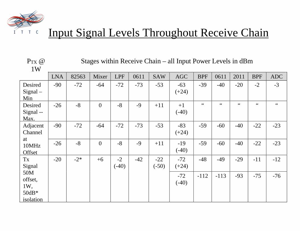
PTX @1W
Stages within Receive Chain – all Input Power Levels in dBm
LNA 82563 Mixer LPF 0611 SAW AGC BPF 0611 2011 BPF ADC
DesiredSignal –Min
-90 -72 -64 -72 -73 -53 -63(+24)
-39 -40 -20 -2 -3
DesiredSignal --Max.
-26 -8 0 -8 -9 +11 +1(-40)
“ “ “ “ “
-90 -72 -64 -72 -73 -53 -83(+24)
-59 -60 -40 -22 -23AdjacentChannelat10MHzOffset
-26 -8 0 -8 -9 +11 -19(-40)
-59 -60 -40 -22 -23
-72(+24)
-48 -49 -29 -11 -12TxSignal50Moffset,1W,50dB*isolation
-20 -2* +6 -2(-40)
-42 -22(-50)
-72(-40)
-112 -113 -93 -75 -76
Input Signal Levels Throughout Receive Chain

Receive Signal Levels
0 2 4 6 8 10 12-100
-80
-60
-40
-20
0
20
Stage
Power Levels for Various Signals throughout Receive Stages
Min. Rcr SignalMax. Rcr SignalAdj. ChannelTx. Signal
Signal Level[dBm]

System Noise Figure
LNA
Cable
Amp1
Mixer
LPF
Amp2
Cable
SAW
AGC Amp3
Amp4BPF
BPF0
0.5
1
1.5
2
2.5Total Cascaded System NoiseFi
Stage
NoiseFigure[dB]

Receiver, IF to ADC
+18dB+20dBAGC ADC
from RFboard
SAW FilterSawtek 854665
70 MHz CF10 MHz BW
Ins. Losss = -10 dB
RF2607
+45dB to -35dBNF = 5dB
BPF
Imped. MatchingIns.Loss= -1dB
MSA0611 MGA2011 BPF
Imped. MatchingIns.Loss= -1dB
NF=3dBP1dB=+2dBm
NF=3dBP1dB=+8dBm
to DigitalStage
12 bitfs=40MSPS80dB SFDRinput: -3dBm
12
-63dBm -39dBm -40dBm -20dBm -2dBm -3dBm-53dBm

Receiver, IF to ADC
A/DConverter,40MSPS
IF Testpoint,-20dB down
70MHzSAW Filter
IF Input,from RF board
AGC Amp. +40dB Amplifier Chain
Aux. Input
AGC Output
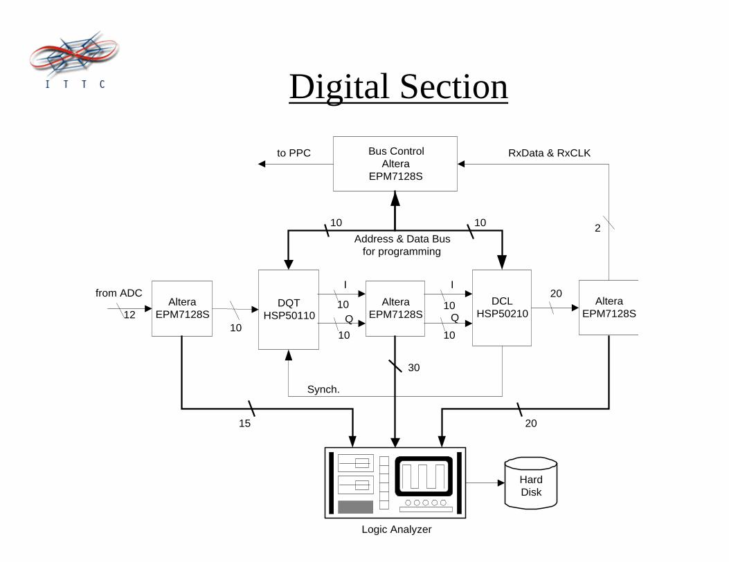
Digital Section
AlteraEPM7128S
AlteraEPM7128S
AlteraEPM7128S
Bus ControlAltera
EPM7128S
DCLHSP50210
DQTHSP50110
HardDisk
Logic Analyzer
12
Address & Data Busfor programming
10 10
from ADC
RxData & RxCLK
2
to PPC
Synch.
I
Q
I
Q
20
10
10
10
10
10
15 20
30
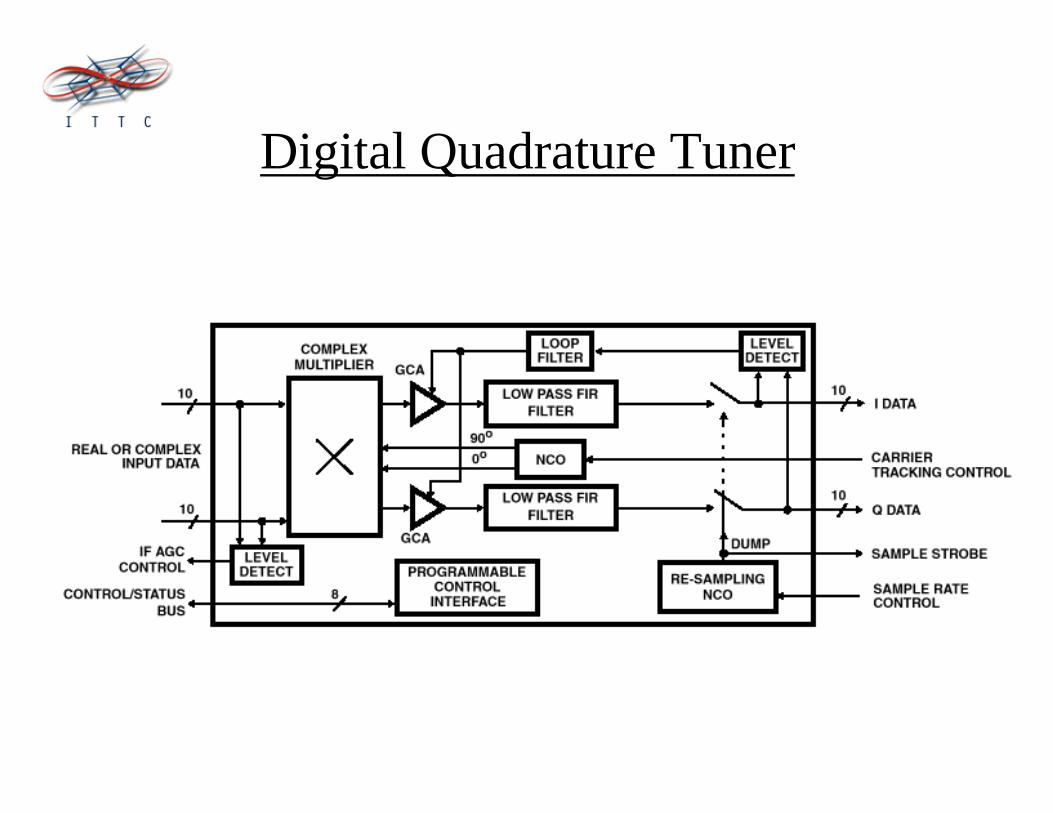
Digital Quadrature Tuner
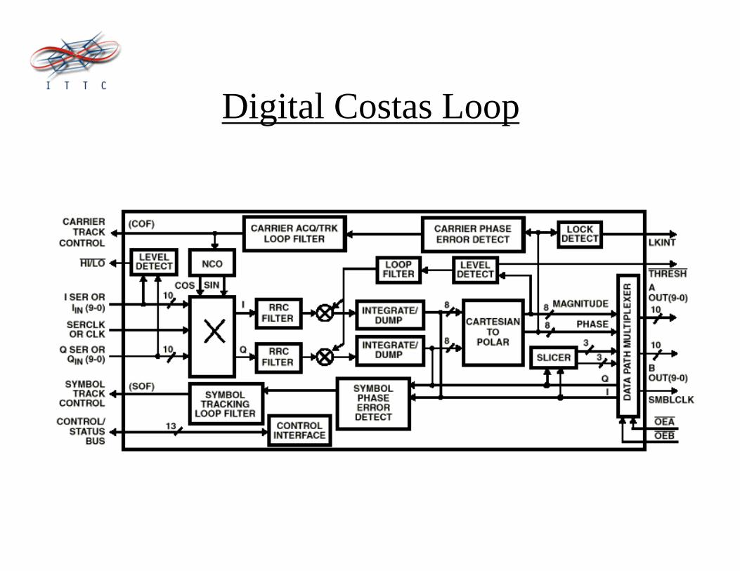
Digital Costas Loop
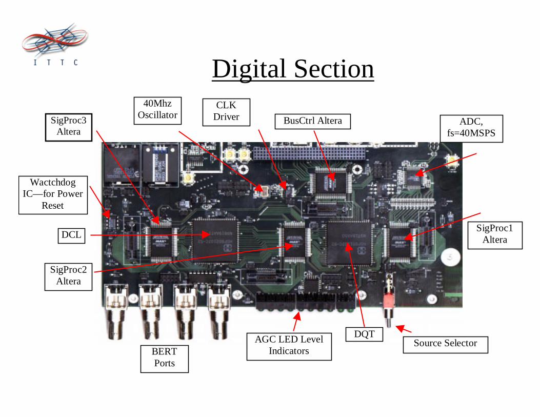
Digital Section
SigProc3Altera
BusCtrl Altera
AGC LED LevelIndicators
Source SelectorBERTPorts
DQT
DCLSigProc1
Altera
ADC,fs=40MSPS
SigProc2Altera
WactchdogIC—for Power
Reset
40MhzOscillator
CLKDriver
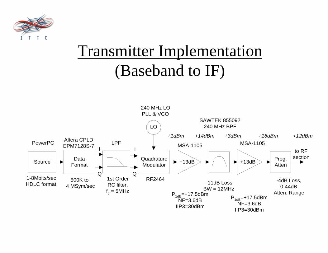
Transmitter Implementation(Baseband to IF)
SourceData
FormatQuadratureModulator
LO
I
Q
I
Q
PowerPC LPF
240 MHz LOPLL & VCO
RF2464
MSA-1105
SAWTEK 855092240 MHz BPF
MSA-1105
+13dB
1-8Mbits/secHDLC format
Prog.Atten
+13dB
to RFsection
Altera CPLDEPM7128S-7
500K to 4 MSym/sec
1st OrderRC filter,fc = 5MHz
-11dB LossBW = 12MHz
P1dB=+17.5dBmNF=3.6dB
IIP3=30dBm
P1dB=+17.5dBmNF=3.6dB
IIP3=30dBm
-4dB Loss,0-44dB
Atten. Range
+1dBm +14dBm +3dBm +16dBm +12dBm

Close Up View of Tx IF Stage
10MHzOscillator
10MHzReference Outputs,
to RF Board
IFTransmitOutput,to RFBoard
240MHzSAWfilter
240MHzPLL &VCO
RF2464Modulator
Prog.Attenuators
Drive Cktfor Modulator
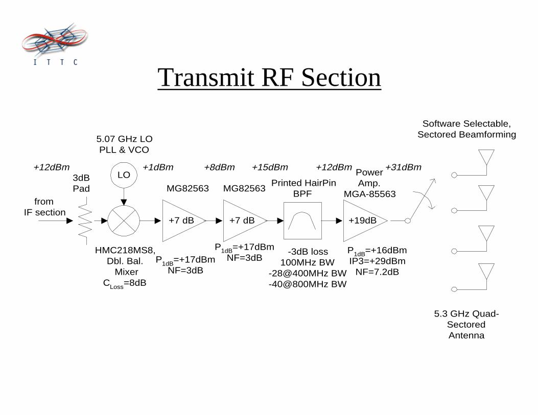
Transmit RF Section
LO
5.07 GHz LOPLL & VCO
HMC218MS8,Dbl. Bal. Mixer
CLoss=8dB
Printed HairPinBPF
MG82563 MG82563
5.3 GHz Quad-SectoredAntenna
Software Selectable,Sectored Beamforming
+7 dB +7 dB +19dB
3dBPad
fromIF section
PowerAmp.
MGA-85563
-3dB loss100MHz BW
-28@400MHz BW-40@800MHz BW
P1dB=+17dBmNF=3dB
P1dB=+17dBmNF=3dB
P1dB=+16dBmIP3=+29dBm
NF=7.2dB
+1dBm +12dBm+8dBm +15dBm +31dBm+12dBm

Transmit RF
10MHzInput
IF Input
RF Output,to PA andAntenna
2.5 GHzVCO
PLL
RF Mixer
x2FrequencyDoubler

Summary
• Software controlled radio with modular RF front ends foruse in channel estimation.
• High-Speed (up to 8 Mbps) wireless radio which iscapable of physical layer and data-link layer adaptability.
• Use this radio “platform” to develop protocols and algorithms to control the physical & data-link layer.
• Real time channel estimation and the use of theseparameters in the above adaptation algorithms.
Future Work

Sub-Sampling
F [MHZ]0
0
0
70-70
F [MHZ]
f
-40 40
fs/2-fs/2
fs=40M
0.25fs
= 10M
Spectrumto be
sampled
convolvedwith
samples
DigitalSpectrum
LH
L
Ls
H
ff
fk
k
ff
k
f
−<
<<+
:isk of valuemaximum thewhere
2
1
2
How to choose fs ,
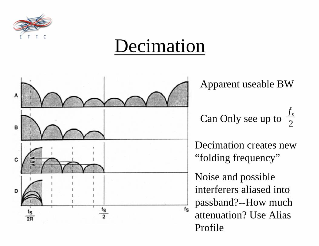
Decimation
Apparent useable BW
Can Only see up to
Decimation creates new“folding frequency”
Noise and possibleinterferers aliased intopassband?--How muchattenuation? Use AliasProfile
2sf

Digital Quadrature Tuner, detail
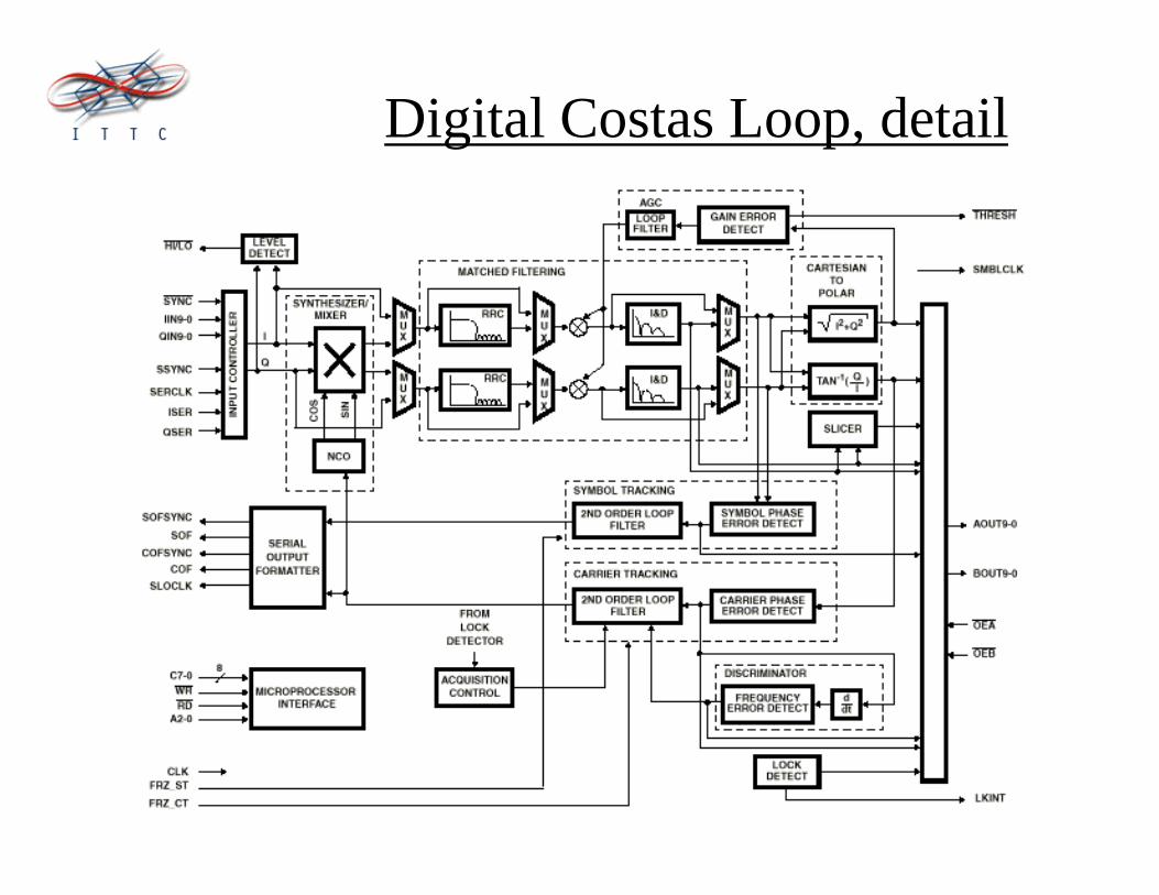
Digital Costas Loop, detail