Fuzzy logic implementation on embedded microcomputers and control systems

Design and Implementation of a Digitalized Fuzzy Logic ControllerFor DC Servo Drives
Hung-Ching LuDepartment of Electrical Engineering
Tatung UniversityNo. 40, Sec. 3, Chung Shan North Road
TAIPEI, 10451, TAIWAN
Abstract: - In this paper, a high performance of fuzzy logic controller for DC servo motor is developed. Thesystem design and implementation procedure of DC servo motor drive using digital signal processing chipTMS320C14 are described. Some experimental results are shown to verify the proposed controller.
Key-Words: - Fuzzy logic controller, Digital signal processing, DC servo motor
1 IntroductionThere are many applications of servo motor [1]-[5],such as numerical control machine tools, industrialrobots, medical equipments, office machines,measuring equipments, and computer peripherals.Generally, the equipments and machinery are used tosave energy and promote automation, which allowsfor high productivity and also produces qualityproducts. The equipment is becoming more technicalwith the application of servo motors, and the needsfor characteristics of servo motor are getting morespecific, especially more compact, light weight andhigh output.
DC motors are widely used in manyvariable-speed drive systems [4]-[5]. The versatilecontrol characteristics of DC motors havecontributed to their extensive use in manyapplications. DC motor can prove high startingtorques, which are required for traction drives.Besides, control over a large speed range both belowand above the rated speed can be easily achieved. Thesimplicity and flexibility of control of DC motorshave made them suitable for variable-speed driveapplications. In fact, a majority of industrial drivestoday use DC machines.
In recent years, the rapid technological progressin microelectronics and power electronics has clearlyhad a significant impact on motor control systemsand their applications [1]-[2], [6]. Consequently,present trends in servo drive technology are towardfully digital speed and position control and eventorque control systems [7]-[14]. The strategy is toutilize the computational power of themicroprocessors and their storage capabilities forcorrective, decoupling and predictive feed forwardcontrol.
Many control algorithms are introduced to gethigh performance, such as model reference adaptivecontrol [15], self tuning adaptive control [16]-[17],and variable structure control [18]. However, thesedesign methods are always complex and their controlgenerally requires a considerable amount ofcomputation time effective compensation [19]. Onthe contrary, the fuzzy algorithm [11]-[13], [20]-[21]based on intuition and experience which can beregarded as a set of heuristic decision rules is simpleto design. Such no mathematical control algorithmscan be implemented easily in a computer, and theyare straightforward and should not involve anycomputational problem. Fuzzy logic controller hasbeen recently found various applications in theindustry as well as in household appliance. Forcomplex and/or ill-defined systems that are not easilycapture the approximate qualitative aspects of humanknowledge and reasoning. Motivation by thisviewpoint a design procedure of fuzzy logiccontroller for DC servo system is presented in thispaper.
2 Fuzzy Logic Control SystemA typical fuzzy logic controller consists of fourcomponents and the descriptions are stated asfollows:1) Fuzzification Interface: The fuzzification interface
performs a conversion from a crisp point into afuzzy set. The shapes of the membership functionsof the linguistic sets are determined according tothe expert experience.
2) Knowledge Base: The knowledge base commonlyconsists two sections: a database and a rule-base.The database contains the membership functions
Proceedings of the 5th WSEAS Int. Conf. on Artificial Intelligence, Knowledge Engineering and Data Bases, Madrid, Spain, February 15-17, 2006 (pp269-274)

of the fuzzy sets used in the fuzzy rules and therule-base contains a number of fuzzy IF-THENrules.
The canonical fuzzy IF-THEN rules are usuallymade from the following conditions: (a) Obtainingby the expert knowledge and/or operators’ experiences. (b) According to the control behaviorof the users. (c) According to the characteristic ofthe plant. (d) Obtaining by self-learning.
3) Inference Engine: The inference engine thatperforms the fuzzy reasoning upon the fuzzycontrol rules is the main component of the fuzzycontroller. There are varieties of compositionalmethods in fuzzy inference, such as max-mincompositional operation and max-productcompositional operation etc.
4) Defuzzification Interface: The defuzzificationinterface converts the fuzzy output of the rule-baseinto a non-fuzzy value. The center of area is theoften used method in defuzzification.
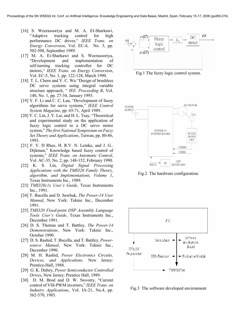
The complete block diagram of the fuzzy controlsystem is depicted in Fig.1. A fuzzy logic controllerof two inputs e(kT), ce(kT) and one output △U(kT)is used for the DC motor control system. In view ofthis figure, e(kT) denotes the error between thepre-defined reference speed (speed command) ωr ,and the motor output speedω(kT) at time instance kT,where k is a positive integer and T is the samplinginterval, ce(kT) denotes the change of the error, and△U(kT) denotes the output change of fuzzy logiccontroller.
3 Hardware and Software Design
3.1 The DSP chip and power-14 system boardDigital signal processing (DSP) emulates thetraditional analog processing methods byimplementing filters and feedback systems using thenumerical methods. In DSP systems, analog signalsare quantized to discrete values using analog todigital converters. After the processing they may beconverted back to the analog domain. Digital controlis similar to the digital signal processing, with analoghardware being replaced by digital hardware. Bysurrounding a high performance DSP with applicableI/O, the processor forms a digital signal controller.The TMS320C14 has made digital signal processingaffordable for low cost control applications.
Next, the TMS320C14 DSP chip and thePower-14 evaluation tool are introduced [22]-[26].
The TMS320C14 DSP chip is a product of TexasInstruments (TI) Incorporated. The ‘C1X family utilizes a modified Harvard architecture for speedand flexibility. In a strict Harvard architecture,program and data memory lie in two separated spacesthat permits a full overlap of instruction fetch andexecution. The ‘C1X family modification of Harvardarchitecture allows the transfers between programand data spaces, thereby increasing the flexibility ofthe device. With a 160-ns instruction cycle, thesedevices are capable of executing up to 6.4 millioninstructions per second (MIPS). The control-specificon–chip peripherals include two 16 bit timers, aversatile timer event manager (timer capture andcompare functions), a watchdog timer, 16 bit digitalI/O, and an asynchronous/ synchronous serialinterface.
Power-14 system board, a product of TeknicIncorporated, is an evaluation tool for developingcontrol application based upon the TMS320C14digital signal controller. Power-14 system boardconsists of a ’C14 processor, emulation hardwareproviding user downloadable program memory,RS-232 communications hardware, a monitorprogram which allows display and modification ofprocessor memories, breakpoint hardware, threechannel of switching servo-amplifier, and an A/Dsubsystem.The I/O configuration logic interfaces the ‘C14
event manager to hardware for controlling devicessuch as motor drive circuit, and for reading feedbackfrom encoders. The I/O logic is broken into two logicblocks: (1) output configuration logic for mappingcompare pins to the servo-amplifier drivers, and (2)input logic to map quadrate inputs and an index pulseto timer inputs.
3.2 The hardware configurationThe hardware configuration of the experimentalsystem is shown in Fig.2. This hardware circuit,includes (1) a TMS320C14 single-chip processor, (2)a dead time control circuit, (3) a base drive amplifier,(4) analog input circuit for A/D converter, (5) a classE chopper power circuit (H bridge configuration),and (6) a scale down circuit from tachogenerator toA/D converter.
Using the internal high double precession PWMmode, and we select timer 2 as a count timer. Thepulse width of each compared output pin isdetermined by the associated compare register, whilethe overall period is determined by the selected timerperiod register (TPR2). Power-14 system boardsupports the dead time circuit, the gate driveamplifier circuit, and the power MOSFET circuit.
Proceedings of the 5th WSEAS Int. Conf. on Artificial Intelligence, Knowledge Engineering and Data Bases, Madrid, Spain, February 15-17, 2006 (pp269-274)

The output configuration logic provides the properpolarity to the actual servo amplifier totem polesections and provides protection from softwarefailure which might enable both switches in aservo-amplifier. We choose the “long” PWM as nooverlap mode, and then the “dead” time can beadjusted as 160 nanosecond. Depending on thecoding of the timers and compare outputs, up to 16bits of digital to analog conversion can be presentedto the servo amplifier.
The tachogenerator voltage is proportional to themotor speed (7 volts/rpm), so the scale down circuitis designed to scale the voltage to the logic voltagelevels and to filter out noise and absorb the abruptvoltage caused from the commutation. The crossreferences of the decimal representation, heximalrepresentation, and the speed units and voltage unitsare shown in Table 1.
3.3 The software designThe fixed-point processors in the TMS320C1xfamily are supported by a full set of hardware andsoftware development tools [25], including theunique scan-based real time emulators, softwaresimulators, and an emulation module. Fig.3 showsthe software developed environment. The assemblylanguage tools create and use common object formatfiles (COFF). COFF object files contain separatedblocks (called sections) of code and data that we canload into different TMS320 memory spaces.
To maximize the manageability and portability ofthe system software, a modular or top-down designtechnique will be used [22], [26]-[27]. Top-downdesign is used to break up a large task into a series ofsmaller tasks or building blocks, which in turn areused to construct a total system in a level-by-levelform. At the end of a top down design process, anumber of modules are linked together which, underthe control a main program, perform as a completesystem. Digital control systems use a number ofstandard blocks, it is therefore likely that a designerwho already has access to one digital control systemwill want to “borrow” some of its functional building blocks to quickly implement a new, different controlunit or reconfigured one. Each software module iswritten as subroutine with a clear and efficientinterface (for parameter passing, stack use, etc) withthe main program.
Now, the overall task can be divided as sevenparts: (1) start up, initialization, (2) user’s interface, read command and call subroutine, (3) thesubroutines (functions), (4) interrupt service routine,(5) debug monitor program that help to developprogram, (6) control algorithm, (7) program library.
To finish this task, the overall program can becomposed of seven modules: (1) the main module, itcontains the start up vector, interrupt vector polling,the initial control process, and interrupt serviceroutines, (2) the global variables module, this moduledefines the global variables in data ram, (3) thecommand module, it can read command from user,such as speed reference, or controller parameters,then call subroutine, (4) the utilities module, itcontains I/O interface to power-14 system board, andsome useful utilities, (5) the monitor module, itcontains debug monitor function, (6) the serialmodule, it is a program library, and (7) thecompensator module, this module is important and itcontains control algorithm which is called from themain module, when a servo control is needed.
To implement different algorithms, such as PIDcontrol or fuzzy control, we can modify thecompensator module, and then link this module withabove six modules. Therefore, the different programswill be generated.
4 Experimental ResultsNow, some experimental results of the speed controlsystem are presented. The controlled plant is used bythe R511T permanent magnet DC servo motor of theSanyo Denki CO., LTD. The nominal parameters ofthe DC motor and tachogenerator are given asfollows[2]. In Table 2, the symbol RP denotes therated output, RE is the rated armature voltage, and
RT is the rated torque, while the symbol ecK is thevoltage gradient of tachogenerator.
The DC power supply of this experiment is fixedas 50 volt, and the PWM chopper frequency is chosenas 8k hertz, or chopping period is 125 micro-second,equivalently. And the servo loop is per 1.025millisecond. Now, the whole system of DC servosystem is established and tested. For the convenienceof explanation, the decimal unit is used to representthe speed command. The relationship of various unitscan be transformed according to Table 1. Forexample, when the speed command is changed form0 to 800 in decimal, it is equivalent form 0 to 999.2micro volts, or form 0 to 770.48 rpm.
Form section 2, it is apparent that the parametersof the fuzzy logic controller are: (1) The set of inputand output variables (i.e., the controller structure), (2)The set of linguistic rules, and (3) The fuzzylanguage. The mathematical operations are chosenfor classification (i.e., mapping from a measurementto a fuzzy set), composition (evaluation of inducedfuzzy restriction of the output) and interpretation (i.e.,
Proceedings of the 5th WSEAS Int. Conf. on Artificial Intelligence, Knowledge Engineering and Data Bases, Madrid, Spain, February 15-17, 2006 (pp269-274)

mapping of the output fuzzy set to a specific controlaction) are also of significance and are the indirectparameters of the controller.
The control rules of the DC servo system areshown in Table 3. In these control rules, sevenlinguistic fuzzy sets are applied for all the input andoutput fuzzy variables. These fuzzy sets are shown as:NB (negative big), NM (negative medium), NS(negative small), PB (positive big), PM (positivemedium), PS (positive small), and ZE (zero).
In the control rules, the linguistic fuzzy sets areused to describe the system variables. We mustdefine membership function to describe the fuzzy setfor fuzzification. The membership function is definedas shown in Fig.4, which is applied to all the inputand output fuzzy sets. The universal sets E,CE, and Uare all defined on the interval [-6, 6], and the centrepoint of the fuzzy sets NB, NM, NS, ZE, PS, PM, PB,are -6, -4, -2, 0, 2, 4, 6, respectively.
Next, the experiment results are given. Fig.5shows the response waveform of fuzzy logiccontroller when speed command is from 0 to 800. Inview of this figure, it has no overshoot and it has thesmaller settling time.
Fig.6 shows the step response waveform whenspeed command is changed from -800 to 800.
Finally, the speed command is changed fromhigh speed to low speed, say, from 800 to 10, theresponse is shown in Fig.7. Obviously, theseexperiment result are satisfactory.
5 Conclusion
In this paper, design and implementation proceduresof a high performance fuzzy logic controller usingTMS320C14 DSP chip for DC motor drive systemhave been presented. Since the uncertainty, externaldisturbance, and nonlinear phenomena are alwaysexisted in the actual servo systems, a digitalizationfuzzy logic controller is proposed to further obtainthe good dynamic speed responses. The presentedcontroller is to make the system with tracking abilityand make it more robust. Finally, the satisfactoryperformance of the proposed controller is confirmedby the experimental result in control applications.
Acknowledgement
This work was supported by the National ScienceCouncil of the Republic of China under the contractof NSC 92-2213-E036-007.
References:[1] Y. Dote, Servo Motor and Motion Control Using
Digital Signal Processors, New Jersey:Prentice-Hall, 1990.
[2]P. C. Sen, “Electric motor drives and control-past,resent, and future,” IEEE. Trans. on IndustrialElectronics, Vol. IE-37, No. 6, pp.562-575,December 1990.
[3] DC Servo Motor, Super R Series, Catalogue ofSanyo Denki CO., LTD., 1992.
[4] P.C. Sen, Thyristor DC Drives, New York: Wielyand Sons Inc., 1981.
[5] T. Kenjo and S. Nagamori, Permanent-Magnentand Brushless DC Motors, New York: Oxford,1985.
[6] P. Vas, Vector Control of AC Machine, NewYork: Oxford, 1990.
[7] A. Nabel, S. Ogasawara, and H. Akagi, “A novel control scheme for current-controlled PWMinverters,” IEEE Trans. on Industry Applications,Vol. IA-22, No. 4, pp. 697-701, July/August1986.
[8] H. W. V. D. Broeck, H. C. Skudelny, and G. V.Stank, “Analysis and realization of a pulse width modulator base on voltage space vectors,“ IEEETrans. on Industry Applications, Vol. IA-24, No.1, January/February 1988.
[9] C. Marchand and A. R. D. D. Ceng, “Optimal torque operation of digitally controlledpermanent synchronous motor drives,“ IEEProceedings-B, Vol. 140, No. 3, pp 232-240,May 1993.
[10] M. Braae and D. A. Rutherford, “Selection of parameters for a fuzzy logic controller,” FuzzySet and Systems, Vol. 2, pp. 185-199, 1979.
[11]C. C. Lee, “Fuzzy logic in control system: fuzzy logic controller-part I,” IEEE Trans. on Systems,Man, and Cybernetics, Vol. SMC-20, No. 2, pp.404-418, March/April 1990.
[12]C. C. Lee, “Fuzzy logic in control system: fuzzy logic controller-part II,” IEEE Trans. onSystems, Man, and Cybernetics, Vol. SMC-20,No. 2, pp. 419-435, March/April 1990.
[13] C. H. Chou and H. C. Lu, “Design of a real-timefuzzy controller for hydraulic servosystems,“ Computers in Industry, Vol. 22, pp.129-142, 1993.
[14] Y. Desheng and Y. Rong, “Grey predictor controller for DC speed-control system,“ TheJournal of Grey System, Vol. 2, pp. 189-215,1990.
[15] N. Matsui, “DSP-based adaptive control ofbrushless motor, “IEEE Trans. on IndustryApplications, Vol. IA-28. No. 2, pp. 448-454,March/April 1992.
Proceedings of the 5th WSEAS Int. Conf. on Artificial Intelligence, Knowledge Engineering and Data Bases, Madrid, Spain, February 15-17, 2006 (pp269-274)
[16] S. Weerasooriya and M. A. EI-Sharkawi,“Adaptive tracking control for high performance DC drives,“ IEEE Trans. onEnergy Conversion, Vol. EC-4, No. 3, pp.502-508, September 1989.
[17] M. A. Ei-Sharkawi and S. Weerasooriya,“Development and implementation of self-turning tracking controller for DCmotors,“ IEEE Trans. on Energy Conversion,Vol. EC-5, No. 1, pp. 122-128, March 1990.
[18] T. L. Chern and Y. C. Wu “Design of brushless DC servo systems using integral variablestructure approach, “ IEE. Proceeding B, Vol.140, No. 1, pp. 27-34, January 1993.
[19]Y. F. Li and C. C. Lau, “Development of fuzzy algorithms for servo systems,” IEEE ControlSystem Magazine, pp. 65-71, April 1989.
[20] Y. C. Lin, J. Y. Lai, and H. L. Tsay,“Theoretical and experimental study on the application offuzzy logic control to a DC servo motorsystem,” The first National Symposium on FuzzySet Theory and Applications, Taiwan, pp. 80-86,1993.
[21] F. V. D Rhee, H. R.V. N. Lemke, and J. G..Dijkman,” Knowledge based fuzzy control of systems,” IEEE Trans. on Automatic Control,Vol. AC-35, No. 2, pp. 148-152, February 1990.
[22] K. S. Lin, Digital Signal ProcessingApplications with the TMS320 Family Theory,algorithm, and Implementations, Volume 1,Texas Instruments Inc., 1989.
[23] TMS320c1x User’s Guide, Texas InstrumentsInc., 1991.
[24] T. Bucella and D. Sewhuk, The Power-14 UserManual, New York: Teknic Inc., December1991.
[25] TMS320 Fixed-point DSP Assembly LanguageTools User’s Guide, Texas Instruments Inc.,December 1991.
[26] D. S. Thomas and T. Battley, The Power-14Demonstrations, New York: Teknic Inc.,October 1990.
[27] D. S. Rashid, T. Bucella, and T. Battley, Power-source Manual, New York: Teknic Inc.,December 1990.
[28] M. H. Rashid, Power Electronics Circuits,Devices, and Applications. New Jersey:Prentice-Hall, 1988.
[29] G. K. Dubey, Power Semiconductor ControlledDrives, New Jersey: Prentice Hall, 1989.
[30] D. M. Brod and D. W. Novotry, “Current control of VSI-PWM inverters,” IEEE Trans. onIndustry Applications, Vol. IA-21, No.4, pp.562-570, 1985.
Fig.1 The fuzzy logic control system.
POWER-14SYSTEM BOARD SCALE
DOWNCKT
POWERSUPPLY
PCCRT
KEYBOARD
USER0
USER1
RS232
DC MOTOR
T.G.
Fig.2 The hardware configuration.
Fig.3 The software developed environment
Proceedings of the 5th WSEAS Int. Conf. on Artificial Intelligence, Knowledge Engineering and Data Bases, Madrid, Spain, February 15-17, 2006 (pp269-274)

Fig.4 The membership function
Fig.5 The step response of fuzzy controllerSpeed=0 to 800.
Fig.6 The step response of fuzzy controllerSpeed= -800 to 800.
Fig.7 The response of fuzzy controllerSpeed= 800 to 10.
Table 1 The cross reference table.
Table 2 The control rule.
Table 3 Parameters of motor and tachogenerator
Proceedings of the 5th WSEAS Int. Conf. on Artificial Intelligence, Knowledge Engineering and Data Bases, Madrid, Spain, February 15-17, 2006 (pp269-274)