DESIGN AND FREEFORM FABRICATION OF COMPLIANT CELLULAR ...ppmdlab/files/SFF.gaurav.FINAL.pdf ·...
17
DESIGN AND FREEFORM FABRICATION OF COMPLIANT CELLULAR MATERIALS WITH GRADED STIFFNESS Guarav Gupta, JunJay Tan, and Carolyn Conner Seepersad Mechanical Engineering Department The University of Texas at Austin, Austin, TX 78712 Abstract Typically, cellular materials are designed for structural applications to provide stiffness or absorb impact via permanent plastic deformation. Alternatively, it is possible to design compliant cellular materials that absorb energy via recoverable elastic deformation, allowing the material to spring back to its original configuration after the load is released. Potential applications include automotive panels or prosthetic applications that require repeated, low-speed impact absorption without permanent deformation. The key is to arrange solid base material in cellular topologies that permit high levels of elastic deformation. To prevent plastic deformation, the topologies are designed for contact between cell walls at predetermined load levels, resulting in customized, graded stiffness profiles. Design techniques are established for synthesizing cellular topologies with customized compliance for static or quasi-static applications. The design techniques account for cell wall contact, large scale deformations, and material nonlinearities. Resulting cellular material designs are fabricated with selective laser sintering, and their properties are experimentally evaluated. 1. Introduction The challenge of designing many engineered components is not to maximize their rigidity but to build in an appropriate level of compliance or flexibility. In automotive applications, for example, a next-generation bumper or body panel would absorb and cushion the low-speed impact of an undetected obstacle, a child’s toy, or a pedestrian and spring back into its original shape repeatedly without damaging itself or the obstacle. For military, sports, or prosthetic applications, exoskeletons would absorb energy from impact or store and release energy from ground contact as a supplement to human movement. Motivated by these and other types of applications, we are designing and fabricating compliant structures from cellular materials. Cellular materials are materials with designed mesostructure in the form of topological arrangements of solid base material and voids with characteristic length scales on the order of micrometers to millimeters. Many natural materials such as wood and bone have cellular configurations that serve several functions, including transport, diffusion, flexibility, and lightweight strength. In engineering applications, metallic cellular or honeycomb materials are used in aerospace sandwich structures for lightweight stiffness, strength, and impact absorption, and polymeric cellular materials or foams are used for thermal insulation and packaging. In most commercial and research applications, structural cellular materials are designed either to provide stiffness or to absorb impacts via permanent plastic deformation and collapse [1].
Transcript of DESIGN AND FREEFORM FABRICATION OF COMPLIANT CELLULAR ...ppmdlab/files/SFF.gaurav.FINAL.pdf ·...
DESIGN AND FREEFORM FABRICATION OF COMPLIANT CELLULAR MATERIALS WITH GRADED STIFFNESS
Guarav Gupta, JunJay Tan, and Carolyn Conner Seepersad
Mechanical Engineering Department The University of Texas at Austin, Austin, TX 78712
Abstract
Typically, cellular materials are designed for structural applications to provide stiffness or absorb impact via permanent plastic deformation. Alternatively, it is possible to design compliant cellular materials that absorb energy via recoverable elastic deformation, allowing the material to spring back to its original configuration after the load is released. Potential applications include automotive panels or prosthetic applications that require repeated, low-speed impact absorption without permanent deformation. The key is to arrange solid base material in cellular topologies that permit high levels of elastic deformation. To prevent plastic deformation, the topologies are designed for contact between cell walls at predetermined load levels, resulting in customized, graded stiffness profiles. Design techniques are established for synthesizing cellular topologies with customized compliance for static or quasi-static applications. The design techniques account for cell wall contact, large scale deformations, and material nonlinearities. Resulting cellular material designs are fabricated with selective laser sintering, and their properties are experimentally evaluated. 1. Introduction
The challenge of designing many engineered components is not to maximize their rigidity but to build in an appropriate level of compliance or flexibility. In automotive applications, for example, a next-generation bumper or body panel would absorb and cushion the low-speed impact of an undetected obstacle, a child’s toy, or a pedestrian and spring back into its original shape repeatedly without damaging itself or the obstacle. For military, sports, or prosthetic applications, exoskeletons would absorb energy from impact or store and release energy from ground contact as a supplement to human movement.
Motivated by these and other types of applications, we are designing and fabricating
compliant structures from cellular materials. Cellular materials are materials with designed mesostructure in the form of topological arrangements of solid base material and voids with characteristic length scales on the order of micrometers to millimeters. Many natural materials such as wood and bone have cellular configurations that serve several functions, including transport, diffusion, flexibility, and lightweight strength. In engineering applications, metallic cellular or honeycomb materials are used in aerospace sandwich structures for lightweight stiffness, strength, and impact absorption, and polymeric cellular materials or foams are used for thermal insulation and packaging. In most commercial and research applications, structural cellular materials are designed either to provide stiffness or to absorb impacts via permanent plastic deformation and collapse [1].
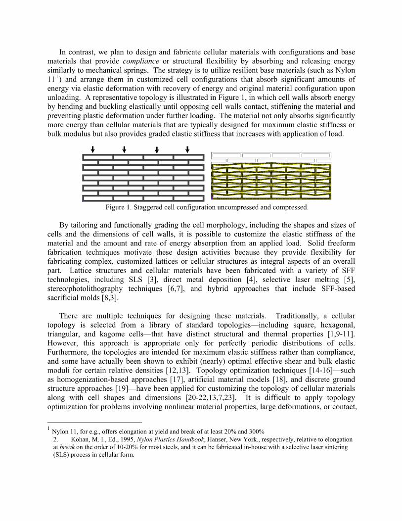
In contrast, we plan to design and fabricate cellular materials with configurations and base materials that provide compliance or structural flexibility by absorbing and releasing energy similarly to mechanical springs. The strategy is to utilize resilient base materials (such as Nylon 111) and arrange them in customized cell configurations that absorb significant amounts of energy via elastic deformation with recovery of energy and original material configuration upon unloading. A representative topology is illustrated in Figure 1, in which cell walls absorb energy by bending and buckling elastically until opposing cell walls contact, stiffening the material and preventing plastic deformation under further loading. The material not only absorbs significantly more energy than cellular materials that are typically designed for maximum elastic stiffness or bulk modulus but also provides graded elastic stiffness that increases with application of load.
Figure 1. Staggered cell configuration uncompressed and compressed.
By tailoring and functionally grading the cell morphology, including the shapes and sizes of
cells and the dimensions of cell walls, it is possible to customize the elastic stiffness of the material and the amount and rate of energy absorption from an applied load. Solid freeform fabrication techniques motivate these design activities because they provide flexibility for fabricating complex, customized lattices or cellular structures as integral aspects of an overall part. Lattice structures and cellular materials have been fabricated with a variety of SFF technologies, including SLS [3], direct metal deposition [4], selective laser melting [5], stereo/photolithography techniques [6,7], and hybrid approaches that include SFF-based sacrificial molds [8,3].
There are multiple techniques for designing these materials. Traditionally, a cellular
topology is selected from a library of standard topologies—including square, hexagonal, triangular, and kagome cells—that have distinct structural and thermal properties [1,9-11]. However, this approach is appropriate only for perfectly periodic distributions of cells. Furthermore, the topologies are intended for maximum elastic stiffness rather than compliance, and some have actually been shown to exhibit (nearly) optimal effective shear and bulk elastic moduli for certain relative densities [12,13]. Topology optimization techniques [14-16]—such as homogenization-based approaches [17], artificial material models [18], and discrete ground structure approaches [19]—have been applied for customizing the topology of cellular materials along with cell shapes and dimensions [20-22,13,7,23]. It is difficult to apply topology optimization for problems involving nonlinear material properties, large deformations, or contact,
1 Nylon 11, for e.g., offers elongation at yield and break of at least 20% and 300%
2. Kohan, M. I., Ed., 1995, Nylon Plastics Handbook, Hanser, New York., respectively, relative to elongation at break on the order of 10-20% for most steels, and it can be fabricated in-house with a selective laser sintering (SLS) process in cellular form.
although researchers have made significant progress in overcoming these challenges (e.g., [24-27]). However, for large regions of non-uniform cellular materials requiring hundreds or thousands of unique interacting cells, topology optimization would entail extremely large numbers of variables, lengthy computational times, and extensive post-processing to obtain a final topology.
Instead, we propose an approximate topology design technique for tailoring compliant material mesostructures. The technique involves generating concepts for compliant cell topologies, populating the design domain with the topology, and then parametrically adjusting it for customized properties. Adjustment is guided by optimization algorithms that can be coupled with finite element analysis or with surrogate or approximate models developed from a series of experimental data points obtained from finite element analysis (with contact and large deformation capabilities). The technique is similar in approach to that of Wang and coauthors [28,7] who focus on developing approximate unit cell models for lattice structures with nonlinear deformation and material properties; however, our approach accommodates contact and freeform geometry with a predetermined unit cell topology.
In the following section, we describe our approach for designing compliant cellular materials.
In the remaining sections, we outline the application of the method to several examples and compare the results with experimental properties of samples fabricated with selective laser sintering.
2. Method
Two alternative approaches are presented for designing complaint structures with graded stiffness. The first approach is focused on achieving graded or increasing stiffness with applied load. The second approach is focused on customizing stiffness according to location. 2.1 Design Approach for Graded Stiffness with Applied Load
The purpose of this approach is to design compliant cellular structures with structural elastic stiffness that varies with the magnitude of applied load. Typically, the structures are designed for relatively low effective elastic stiffness under initial loading. Then, they are designed to stiffen as the magnitude of the applied load increases and to exhibit resiliency under a specified range of quasi-static loads by returning to their original form as the applied load is released. The strategy for achieving low effective elastic stiffness is to identify cellular topologies that subject cell walls to transverse loads and elastic bending rather than axial loads and deformation, for which the structures tend to be stiffer. The strategy for increasing the effective elastic stiffness as the magnitude of the load increases is to initiate contact in the cell walls which stiffens the structure and prevents significant additional cell wall bending and yielding.
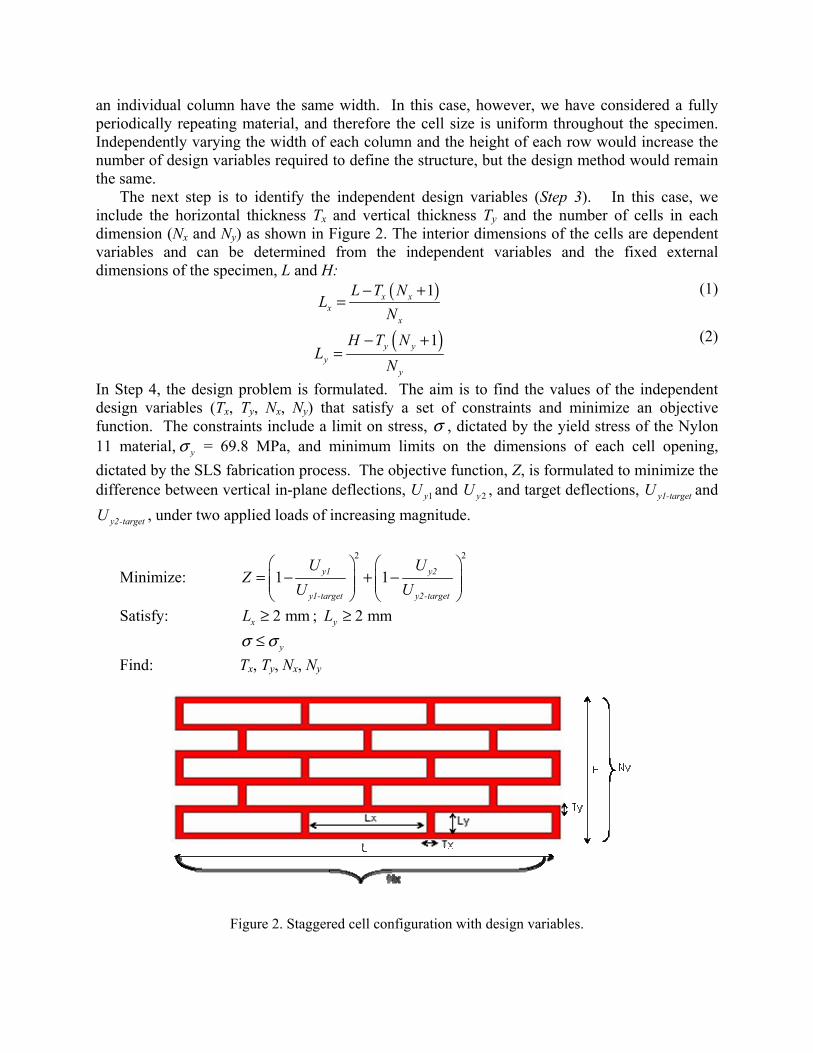
As documented in Figure 3, the method begins by identifying a compliant cellular topology
as a base design (Step 1). In this paper, the staggered cell configuration illustrated in Figure 2 is selected to demonstrate the approach. The next step (Step 2) is to define a unit cell of the topology as the simplest periodically repeating unit of the material. For geometric feasibility of this basic design, it is essential that cells in an individual row have the same height and cells in
an individual column have the same width. In this case, however, we have considered a fully periodically repeating material, and therefore the cell size is uniform throughout the specimen. Independently varying the width of each column and the height of each row would increase the number of design variables required to define the structure, but the design method would remain the same.
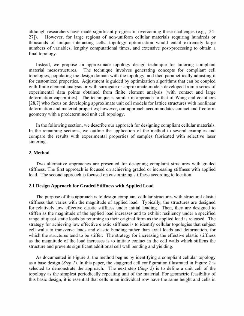
The next step is to identify the independent design variables (Step 3). In this case, we include the horizontal thickness Tx and vertical thickness Ty and the number of cells in each dimension (Nx and Ny) as shown in Figure 2. The interior dimensions of the cells are dependent variables and can be determined from the independent variables and the fixed external dimensions of the specimen, L and H:
( )1x xx
x
L T NL
N− +
= (1)
( )1y yy
y
H T NL
N− +
= (2)
In Step 4, the design problem is formulated. The aim is to find the values of the independent design variables (Tx, Ty, Nx, Ny) that satisfy a set of constraints and minimize an objective function. The constraints include a limit on stress, σ , dictated by the yield stress of the Nylon 11 material, yσ = 69.8 MPa, and minimum limits on the dimensions of each cell opening, dictated by the SLS fabrication process. The objective function, Z, is formulated to minimize the difference between vertical in-plane deflections, 1yU and 2yU , and target deflections, y1-targetU and
y2-targetU , under two applied loads of increasing magnitude.
Minimize: 2 2
1 1y1 y2
y1-target y2-target
U UZ
U U⎛ ⎞ ⎛ ⎞
= − + −⎜ ⎟ ⎜ ⎟⎜ ⎟ ⎜ ⎟⎝ ⎠ ⎝ ⎠
Satisfy: 2 mmxL ≥ ; 2 mmyL ≥ yσ σ≤ Find: Tx, Ty, Nx, Ny
Figure 2. Staggered cell configuration with design variables.
Figure 3. Sequence of steps in designing for graded stiffness with applied load.
The deformation of the cellular structure is evaluated with ANSYS [29] finite element
analysis software (Step 5). Two predetermined loads are applied to the structure, and the vertical deflections, Uy1 and Uy2, are evaluated with ANSYS. The design problem is solved by interfacing ANSYS with optimization algorithms using iSIGHT design integration software (Step 6). A global search is performed using a genetic algorithm, and the solution is refined locally with a sequential quadratic programming (SQP) algorithm in iSIGHT. The results are discussed in Section 3. 2.2 Design Approach for Graded Stiffness with Location
The previous approach is efficient when the geometry is periodically repeated. However, if the cells and corresponding stiffness are varied with location, the number of design variables increases along with the number of design iterations. The problem becomes more difficult to solve efficiently with contact conditions because each design iteration requires an ANSYS evaluation. In the following approach, a parametric approximate model is constructed for a basic unit cell, based on data from detailed ANSYS analyses. The regression model is utilized in place of expensive ANSYS analyses to enable rapid, computationally efficient design of structures with stiffness that varies with location and/or magnitude of applied load.
The strategy here is to populate a geometric domain with individual spring-like structures
with individually customized stiffness profiles. Sample geometries are illustrated in Figure 4, all of which provide variable stiffness with the influence of surface contact. An object, such as a compliant chair pad or vehicle bumper, would be populated with a matrix of these structures, which can be customized to provide targeted force-deflection characteristics for specific applied loads and spatial constraints.
1. Identify a compliant cellular topology as the base design
4. Formulate the design problem
5. Build a finite element model to determine the
6. Solve the design problem to identify
3. Determine the independent design variables in the unit cell
2. Identify a single repeating unit of thestructure
stiffness at predetermined loads
a cell design for target stiffnesses
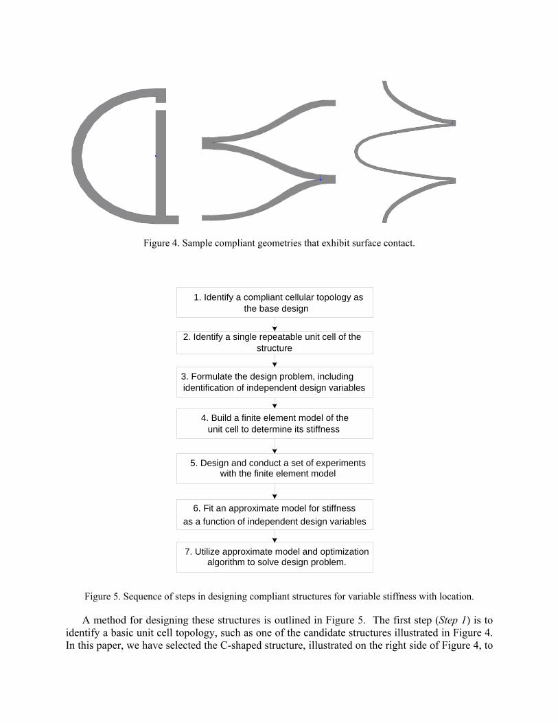
Figure 4. Sample compliant geometries that exhibit surface contact.
Figure 5. Sequence of steps in designing compliant structures for variable stiffness with location.
A method for designing these structures is outlined in Figure 5. The first step (Step 1) is to
identify a basic unit cell topology, such as one of the candidate structures illustrated in Figure 4. In this paper, we have selected the C-shaped structure, illustrated on the right side of Figure 4, to
1. Identify a compliant cellular topology asthe base design
4. Build a finite element model of the unit cell to determine its stiffness
5. Design and conduct a set of experiments with the finite element model
3. Formulate the design problem, including
as a function of independent design variables
7. Utilize approximate model and optimizationalgorithm to solve design problem.
2. Identify a single repeatable unit cell of the structure
6. Fit an approximate model for stiffness
identification of independent design variables
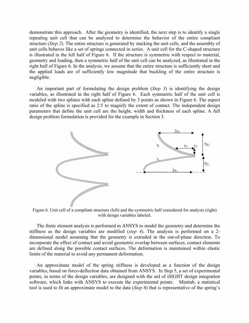
demonstrate this approach. After the geometry is identified, the next step is to identify a single repeating unit cell that can be analyzed to determine the behavior of the entire compliant structure (Step 2). The entire structure is generated by stacking the unit cells, and the assembly of unit cells behaves like a set of springs connected in series. A unit cell for the C-shaped structure is illustrated in the left half of Figure 6. If the structure is symmetric with respect to material, geometry and loading, then a symmetric half of the unit cell can be analyzed, as illustrated in the right half of Figure 6. In the analysis, we assume that the entire structure is sufficiently short and the applied loads are of sufficiently low magnitude that buckling of the entire structure is negligible.
An important part of formulating the design problem (Step 3) is identifying the design
variables, as illustrated in the right half of Figure 6. Each symmetric half of the unit cell is modeled with two splines with each spline defined by 3 points as shown in Figure 6. The aspect ratio of the spline is specified as 2:5 to magnify the extent of contact. The independent design parameters that define the unit cell are the height, width and thickness of each spline. A full design problem formulation is provided for the example in Section 3.
Figure 6. Unit cell of a compliant structure (left) and the symmetric half considered for analysis (right)
with design variables labeled.
The finite element analysis is performed in ANSYS to model the geometry and determine the stiffness as the design variables are modified (step 4). The analysis is performed on a 2-dimensional model assuming that the geometry is extruded in the out-of-plane direction. To incorporate the effect of contact and avoid geometric overlap between surfaces, contact elements are defined along the possible contact surfaces. The deformation is maintained within elastic limits of the material to avoid any permanent deformation.
An approximate model of the spring stiffness is developed as a function of the design
variables, based on force-deflection data obtained from ANSYS. In Step 5, a set of experimental points, in terms of the design variables, are designed with the aid of iSIGHT design integration software, which links with ANSYS to execute the experimental points. Minitab, a statistical tool is used to fit an approximate model to the data (Step 6) that is representative of the spring’s
t2
t1
x2 y2
2x2
5y1
5y2
2x1
vertical deformation as a function of the design variables. In Section 3.2, we apply the method to a representative design problem and discuss the results.
3. Results 3.1 Design Example of Graded Stiffness With Applied Load
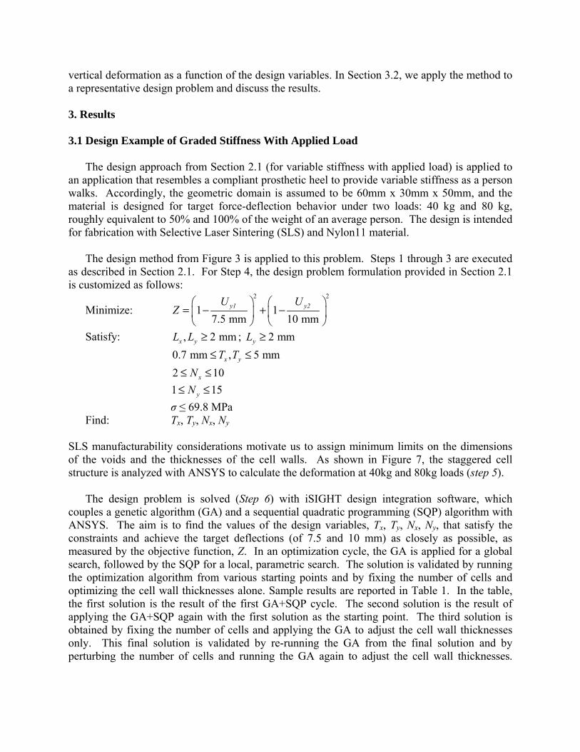
The design approach from Section 2.1 (for variable stiffness with applied load) is applied to an application that resembles a compliant prosthetic heel to provide variable stiffness as a person walks. Accordingly, the geometric domain is assumed to be 60mm x 30mm x 50mm, and the material is designed for target force-deflection behavior under two loads: 40 kg and 80 kg, roughly equivalent to 50% and 100% of the weight of an average person. The design is intended for fabrication with Selective Laser Sintering (SLS) and Nylon11 material.
The design method from Figure 3 is applied to this problem. Steps 1 through 3 are executed
as described in Section 2.1. For Step 4, the design problem formulation provided in Section 2.1 is customized as follows:
Minimize: 2 2
1 17.5 mm 10 mm
y1 y2U UZ
⎛ ⎞ ⎛ ⎞= − + −⎜ ⎟ ⎜ ⎟⎝ ⎠ ⎝ ⎠
Satisfy: , 2 mmx yL L ≥ ; 2 mmyL ≥ 0.7 mm , 5 mmx yT T≤ ≤ 2 10xN≤ ≤ 1 15yN≤ ≤ σ ≤ 69.8 MPa Find: Tx, Ty, Nx, Ny
SLS manufacturability considerations motivate us to assign minimum limits on the dimensions of the voids and the thicknesses of the cell walls. As shown in Figure 7, the staggered cell structure is analyzed with ANSYS to calculate the deformation at 40kg and 80kg loads (step 5).
The design problem is solved (Step 6) with iSIGHT design integration software, which couples a genetic algorithm (GA) and a sequential quadratic programming (SQP) algorithm with ANSYS. The aim is to find the values of the design variables, Tx, Ty, Nx, Ny, that satisfy the constraints and achieve the target deflections (of 7.5 and 10 mm) as closely as possible, as measured by the objective function, Z. In an optimization cycle, the GA is applied for a global search, followed by the SQP for a local, parametric search. The solution is validated by running the optimization algorithm from various starting points and by fixing the number of cells and optimizing the cell wall thicknesses alone. Sample results are reported in Table 1. In the table, the first solution is the result of the first GA+SQP cycle. The second solution is the result of applying the GA+SQP again with the first solution as the starting point. The third solution is obtained by fixing the number of cells and applying the GA to adjust the cell wall thicknesses only. This final solution is validated by re-running the GA from the final solution and by perturbing the number of cells and running the GA again to adjust the cell wall thicknesses.
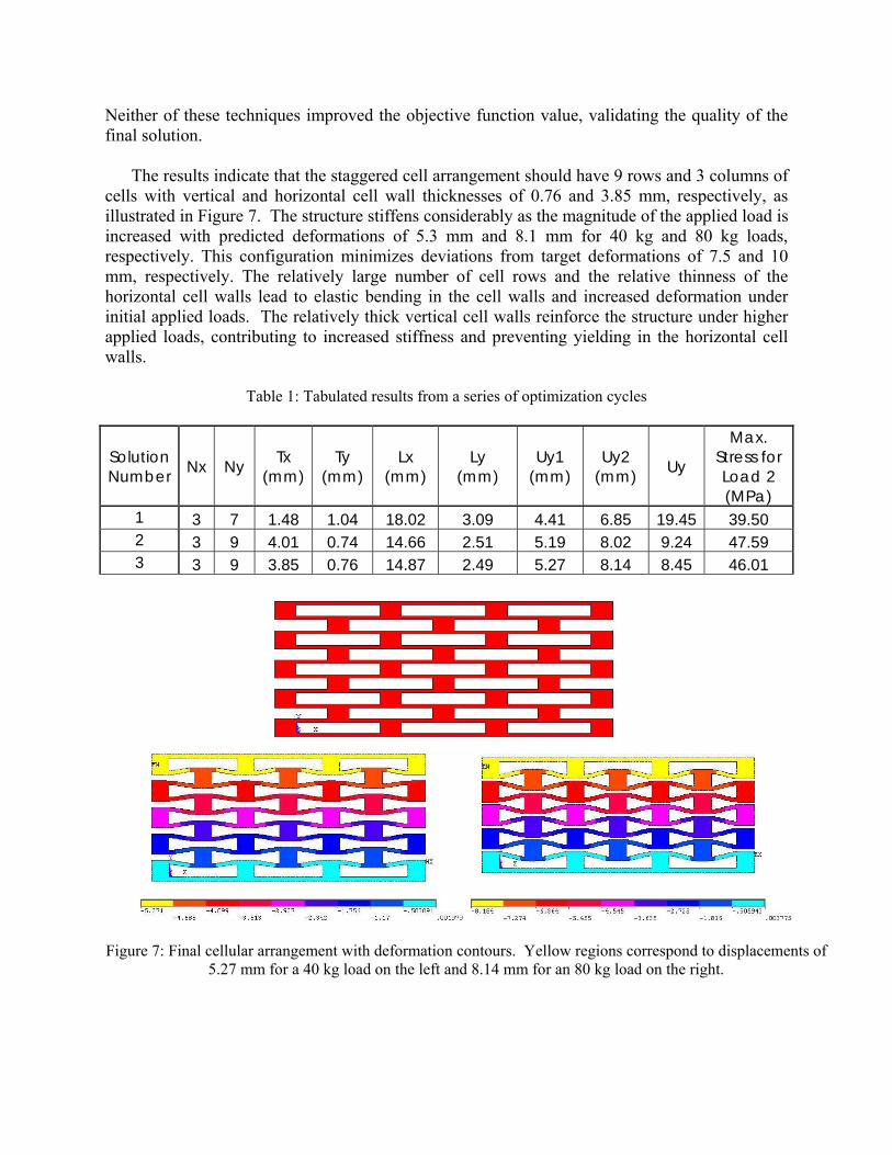
Neither of these techniques improved the objective function value, validating the quality of the final solution.
The results indicate that the staggered cell arrangement should have 9 rows and 3 columns of
cells with vertical and horizontal cell wall thicknesses of 0.76 and 3.85 mm, respectively, as illustrated in Figure 7. The structure stiffens considerably as the magnitude of the applied load is increased with predicted deformations of 5.3 mm and 8.1 mm for 40 kg and 80 kg loads, respectively. This configuration minimizes deviations from target deformations of 7.5 and 10 mm, respectively. The relatively large number of cell rows and the relative thinness of the horizontal cell walls lead to elastic bending in the cell walls and increased deformation under initial applied loads. The relatively thick vertical cell walls reinforce the structure under higher applied loads, contributing to increased stiffness and preventing yielding in the horizontal cell walls.
Table 1: Tabulated results from a series of optimization cycles
Solution Number Nx Ny Tx
(mm) Ty
(mm)Lx
(mm) Ly
(mm) Uy1
(mm) Uy2
(mm) Uy Max.
Stress for Load 2 (MPa)
1 3 7 1.48 1.04 18.02 3.09 4.41 6.85 19.45 39.50 2 3 9 4.01 0.74 14.66 2.51 5.19 8.02 9.24 47.59 3 3 9 3.85 0.76 14.87 2.49 5.27 8.14 8.45 46.01
Figure 7: Final cellular arrangement with deformation contours. Yellow regions correspond to displacements of 5.27 mm for a 40 kg load on the left and 8.14 mm for an 80 kg load on the right.
3.2 Design Example of Graded Stiffness with Location
The design approach from Section 2.2 is applied in this section to design c-shaped structures and a chair pad with variable stiffness from location to location. The c-shaped structure is used to illustrate the effectiveness of approximate models for capturing the force-deflection behavior of a compliant structure as a function of dimensional parameters. The chair pad example is used to illustrate the entire design method outlined in Figure 5.
For the c-shaped structure example, a finite element analysis is performed to determine the
deflection of a symmetric half of the unit cell, illustrated in the right half of Figure 6, as a function of the design variables. In this discussion, we assume that the load is fixed although the method could be repeated for loads of different magnitudes. In the ANSYS finite element analysis, symmetric boundary conditions are applied to the top and bottom of the structure; horizontal displacement is fixed at a point on the bottom of the structure; and the load is applied to the top of the structure as a pressure of 0.02 MPa. A 2D analysis is performed with plane strain conditions, and large deformation static analysis is enabled. The structure is meshed with PLANE42 quadrilateral elements not larger than 0.1mm in dimension.
The experiments are based on a Latin Hypercube design generated in iSIGHT and executed with iterative ANSYS simulations. The bounds for each variable in the experiment are based on the process capabilities of SLS and knowledge of the design space:
1 22 mm , 15 mmx x≤ ≤ (3)
1 21 mm , 7 mmy y≤ ≤ (4)
1 20.7 mm , 3 mmt t≤ ≤ (5)A set of 100 experimental points is generated, and the vertical displacement for each data point is evaluated. The data is approximated with a least squares regression model. Since the geometry closely resembles a helical compression spring, we expect the displacement to be a function of higher order products and quotients of design variables. To capture the effect of higher order terms, the regression model is fit to the logarithms of displacement and design variables. After eliminating insignificant terms and refitting the model, the final approximate model is:
)y+log(x 1.14 + )y+log(x 1.40 + )x+log(x 4.96 + )y+log(t 1.22 + )x+log(t 7.31 + )x+log(t 5.93 - )y+log(t 0.818 +
)x+log(t 6.54 - )x+log(t 6.26 + )t+log(t 5.91 + logx 2.66 -
logx 2.39 - logy 1.12 - logy 0.593 - logt 3.93 - logt 4.66 - 8.05 - = logU
122121
22221211
2111212
12121y
(6)
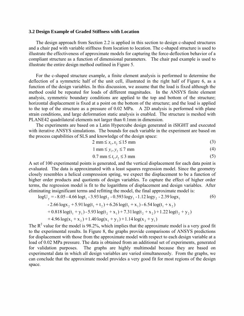
The R2 value for the model is 98.2%, which implies that the approximate model is a very good fit to the experimental results. In Figure 8, the graphs provide comparisons of ANSYS predictions for displacement with those from the approximate model with respect to each design variable at a load of 0.02 MPa pressure. The data is obtained from an additional set of experiments, generated for validation purposes. The graphs are highly multimodal because they are based on experimental data in which all design variables are varied simultaneously. From the graphs, we can conclude that the approximate model provides a very good fit for most regions of the design space.
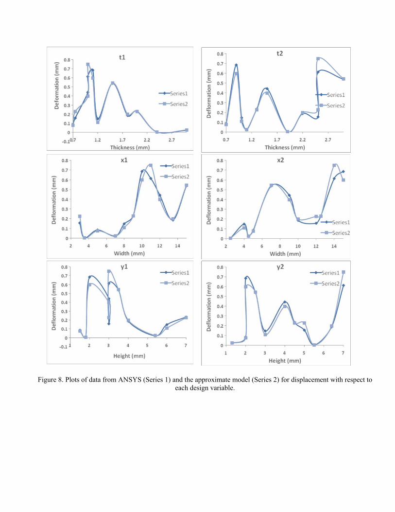
Figure 8. Plots of data from ANSYS (Series 1) and the approximate model (Series 2) for displacement with respect to
each design variable.
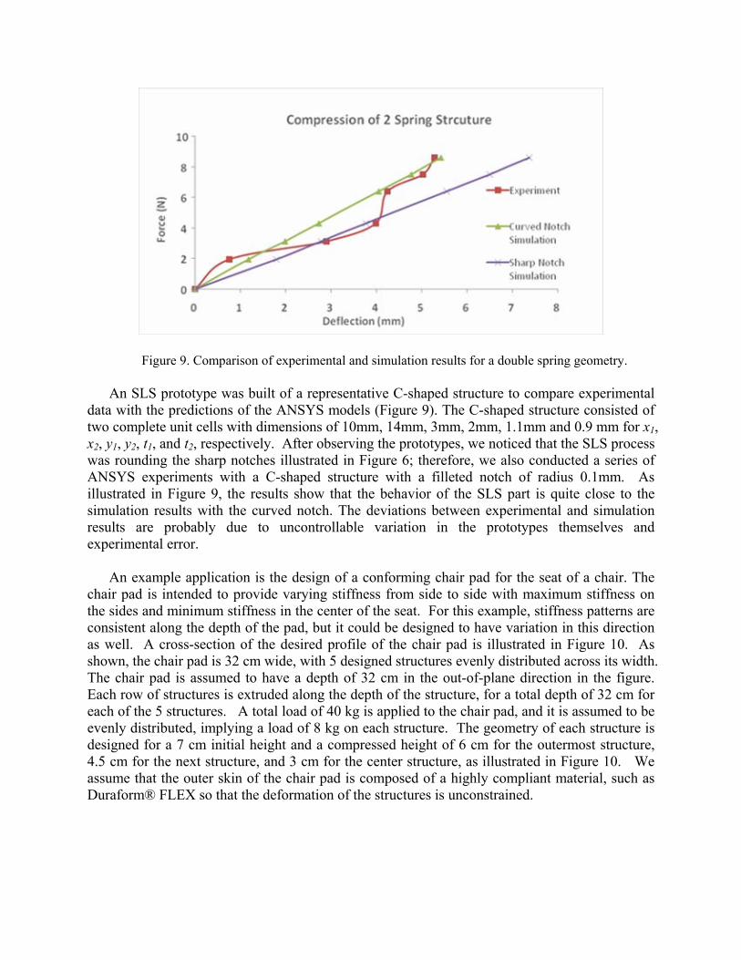
Figure 9. Comparison of experimental and simulation results for a double spring geometry.
An SLS prototype was built of a representative C-shaped structure to compare experimental data with the predictions of the ANSYS models (Figure 9). The C-shaped structure consisted of two complete unit cells with dimensions of 10mm, 14mm, 3mm, 2mm, 1.1mm and 0.9 mm for x1, x2, y1, y2, t1, and t2, respectively. After observing the prototypes, we noticed that the SLS process was rounding the sharp notches illustrated in Figure 6; therefore, we also conducted a series of ANSYS experiments with a C-shaped structure with a filleted notch of radius 0.1mm. As illustrated in Figure 9, the results show that the behavior of the SLS part is quite close to the simulation results with the curved notch. The deviations between experimental and simulation results are probably due to uncontrollable variation in the prototypes themselves and experimental error.
An example application is the design of a conforming chair pad for the seat of a chair. The
chair pad is intended to provide varying stiffness from side to side with maximum stiffness on the sides and minimum stiffness in the center of the seat. For this example, stiffness patterns are consistent along the depth of the pad, but it could be designed to have variation in this direction as well. A cross-section of the desired profile of the chair pad is illustrated in Figure 10. As shown, the chair pad is 32 cm wide, with 5 designed structures evenly distributed across its width. The chair pad is assumed to have a depth of 32 cm in the out-of-plane direction in the figure. Each row of structures is extruded along the depth of the structure, for a total depth of 32 cm for each of the 5 structures. A total load of 40 kg is applied to the chair pad, and it is assumed to be evenly distributed, implying a load of 8 kg on each structure. The geometry of each structure is designed for a 7 cm initial height and a compressed height of 6 cm for the outermost structure, 4.5 cm for the next structure, and 3 cm for the center structure, as illustrated in Figure 10. We assume that the outer skin of the chair pad is composed of a highly compliant material, such as Duraform® FLEX so that the deformation of the structures is unconstrained.
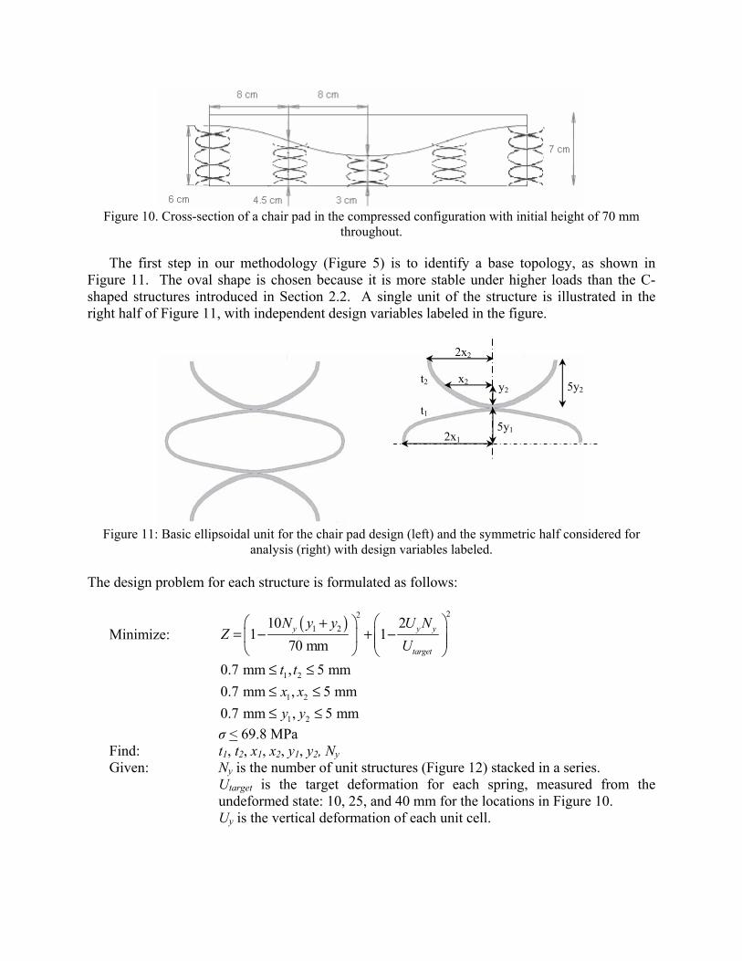
Figure 10. Cross-section of a chair pad in the compressed configuration with initial height of 70 mm
throughout.
The first step in our methodology (Figure 5) is to identify a base topology, as shown in Figure 11. The oval shape is chosen because it is more stable under higher loads than the C-shaped structures introduced in Section 2.2. A single unit of the structure is illustrated in the right half of Figure 11, with independent design variables labeled in the figure.
Figure 11: Basic ellipsoidal unit for the chair pad design (left) and the symmetric half considered for
analysis (right) with design variables labeled. The design problem for each structure is formulated as follows:
Minimize: ( ) 22
1 210 21 1
70 mmy y y
target
N y y U NZ
U⎛ ⎞+⎛ ⎞
= − + −⎜ ⎟⎜ ⎟ ⎜ ⎟⎝ ⎠ ⎝ ⎠
1 20.7 mm , 5 mmt t≤ ≤
1 20.7 mm , 5 mmx x≤ ≤ 1 20.7 mm , 5 mmy y≤ ≤
σ < 69.8 MPa Find: t1, t2, x1, x2, y1, y2, Ny Given: Ny is the number of unit structures (Figure 12) stacked in a series. Utarget is the target deformation for each spring, measured from the
undeformed state: 10, 25, and 40 mm for the locations in Figure 10. Uy is the vertical deformation of each unit cell.
t2
t1
2x1
2x2
5y2 x2 y2
5y1
The objective is to minimize two quantities: (1) the difference between the undeformed height and the 7 cm target value for the initial height of the structure, and (2) the difference between the deformation of each structure and the target deformation, Utarget, of 10 mm, 25 mm, or 40 mm, depending on location, as illustrated in Figure 10.
As described in Section 2.2, a Latin Hypercube experiment is designed in the design variables. Finite element analysis in ANSYS is performed for each data point under the expected load, and a regression model is fit to the results. The regression model for the oval structure is as follows:
2122122111
212212221221
1121112122
21
22
21
22
21212212
2111213212
2212211121
11212112
121212y
y0.00115yy0.00009x-y0.00081xy0.00548x-y0.00765x- x0.00472x-y0.0254t-y0.0151tx0.0125t-x0.0198ty0.0196t
y0.0105tx0.0197tx0.0402tt0.0518t0.00689y0.00068y0.00007x
0.0046x0.108t0.0153t-)y0.129log(y)y0.137log(x-)y0.06log(x
)y0.691log(x-)y0.985log(x-)x1.27log(x)y0.12log(t-)y0.77log(t )x4.43log(t)x2.26log(t-)y0.09log(t-)y1.43log(t)x3.83log(t-
)x0.62log(t)t7.1log(t0.473logy-1.46logy-0.185logx7.04logt
3.94logt0.239y0.034y0.0746x0.348x0.63t0.069t5.25logU 1
+++++
++−+−−+
−−+++++
++++++++++++++
++++−−
−++++++−= (7)
The model is slightly different from that of the C-springs because it also includes an exponential dependence on the variables. The R-squared value for the fit is 98.9%, meaning that the approximation is quite good for the set of experimental points.
The regression model is used to solve the design problem. The proposed geometry is
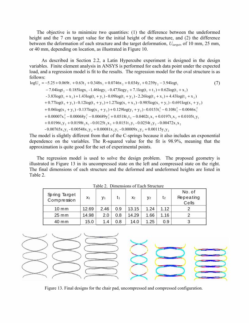
illustrated in Figure 13 in its uncompressed state on the left and compressed state on the right. The final dimensions of each structure and the deformed and undeformed heights are listed in Table 2.
Table 2. Dimensions of Each Structure
Spring Target Compression x1 y1 t1 x2 y2 t2
No. of Repeating
Cells 10 mm 12.69 2.46 0.9 13.15 1.24 1.12 2 25 mm 14.98 2.0 0.8 14.29 1.66 1.16 2 40 mm 15.0 1.4 0.8 14.0 1.25 0.9 3
Figure 13. Final designs for the chair pad, uncompressed and compressed configuration.
4. Conclusion
Design methods have been presented for customizing compliant cellular structures that absorb energy via recoverable elastic deformation, allowing them to spring back to their original configuration after the static or quasi-static load is released. The cellular structures are designed for elastic structural stiffness that varies from location to location or changes with the magnitude of an applied load. For grading the stiffness of cellular structures with the magnitude of applied load, the key strategy is to incorporate contact mechanisms within the cellular structures to stiffen the structures and prevent plastic deformation as the magnitude of the applied load increases. To design these structures, a parametric optimization strategy is provided for varying cell wall thicknesses and spacing to achieve desired stiffness profiles. The approach is used to tailor a staggered cell design, which is subsequently fabricated in SLS with Nylon 11 and experimentally evaluated.
For grading the stiffness of cellular structures from location to location, an approximate
modeling approach is introduced to reduce the computational expense of the design process. The method begins with identifying a unit cell design that is capable of providing desired force-deflection behavior and incorporating contact for increasing stiffness, if desired. In this paper, the unit cells are assumed to be independent of neighboring unit cells in terms of behavior and geometry (i.e., they are stand-alone, non-interlocking unit cells similar to individual mechanical springs). Using designed experiments and regression techniques, an approximate model of the elastic structural stiffness of the unit cell is generated as a function of the variables that define its geometry. The approximate model, rather than expensive finite element analysis, is utilized to significantly reduce the computational time and expense of designing larger structures that are comprised of matrices of unit cells, customized to provide spatially variable stiffness throughout the structures. The method is applied for designing a conformable chair pad with oval shaped spring structures that define a variable stiffness profile in each cross-section of the pad. The performance of the approximate models is compared with empirical data obtained from Nylon 11 structures fabricated with SLS.
Several tasks are planned for on-going work. To date, basic cell topologies have been
intuitively generated, but topology optimization could be applied to identify material layouts for base cells in which surface contact affects the material stiffness. Also, finite element analyses have been limited to static or quasi-static loading, but dynamic loading and fatigue analyses should be considered as well. Finally, the approximate models are generated for stand-alone, non-interlocking structures, applied loads with a single magnitude, and structures that are assumed to have only one degree of freedom. Future work should involve expanding the applicability of these models to consider variable applied loads and additional degrees of freedom. 5. Acknowledgments
We gratefully acknowledge support from the University of Texas at Austin. We owe a special thanks to Brian Nowotny for conducting many of the experiments and to Dr. Rick Neptune for motivating us to consider the prosthetic heel example.

6. References 1. Gibson, L. J. and M. F. Ashby, 1997, Cellular Solids: Structure and Properties,
Cambridge University Press, Cambridge, UK. 2. Kohan, M. I., Ed., 1995, Nylon Plastics Handbook, Hanser, New York. 3. Stampfl, J., H. Fouad, S. Seidler, R. Liska, F. Schwager, A. Woesz and P. Fratzl, 2004,
“Fabrication and Moulding of Cellular Materials by Rapid Prototyping,” International Journal of Materials and Product Technology, Vol. 21, No. 4, pp. 285-296.
4. Oruganti, R. K., A. K. Ghosh and J. Mazumder, 2004, “Thermal Expansion Behavior in Fabricated Cellular Structures,” Materials Science and Engineering A, Vol. 371, pp. 24-34.
5. Brooks, W., C. Sutcliffe, W. Cantwell, P. Fox, J. Todd and R. Mines, 2005, "Rapid Design and Manufacture of Ultralight Cellular Materials," Proceedings of the Solid Freeform Fabrication Symposium (D. L. Bourell, R. H. Crawford, J. J. Beaman, K. L. Wood and H. L. Marcus, Eds.), Austin, TX.
6. Zimbeck, W. R. and R. W. Rice, 1999, "Freeform Fabrication of Components with Designed Cellular Structure," Solid Freeform and Additive Fabrication, Materials Research Society Symposium Proceedings (D. Dimos, S. C. Danforth and M. J. Cima, Eds.), Materials Research Society, Warrendale, PA, Vol. 542.
7. Wang, H., 2005, "A Unit Cell Approach for Lightweight Structure and Compliant Mechanism," Ph.D. Dissertation,G.W. Woodruff School of Mechanical Engineering, Georgia Institute of Technology, Atlanta, GA.
8. Gervasi, V. R. and D. C. Stahl, 2004, "Design and Fabrication of Components with Optimized Lattice Microstructures," Proceedings of the Solid Freeform Fabrication Symposium (D. L. Bourell, R. H. Crawford, J. J. Beaman, K. L. Wood and H. L. Marcus, Eds.), Austin, TX.
9. Evans, A. G., J. W. Hutchinson, N. A. Fleck, M. F. Ashby and H. N. G. Wadley, 2001, “The Topological Design of Multifunctional Cellular Materials,” Progress in Materials Science, Vol. 46, No. 3-4, pp. 309-327.
10. Gu, S., T. J. Lu and A. G. Evans, 2001, “On the Design of Two-Dimensional Cellular Metals for Combined Heat Dissipation and Structural Load Capacity,” International Journal of Heat and Mass Transfer, Vol. 44, No. 11, pp. 2163-2175.
11. Hayes, A. M., A. Wang, B. M. Dempsey and D. L. McDowell, 2004, “Mechanics of Linear Cellular Alloys,” Mechanics of Materials, Vol. 36, No. 8, pp. 691-713.
12. Hyun, S. and S. Torquato, 2000, “Effective Elastic and Transport Properties of Regular Honeycombs for all Densities,” Journal of Materials Research, Vol. 15, No. 9, pp. 1985-1993.
13. Hyun, S. and S. Torquato, 2002, “Optimal and Manufacturable Two-Dimensional, Kagome-Like Cellular Solids,” Journal of Materials Research, Vol. 17, No. 1, pp. 137-144.
14. Eschenauer, H. A. and N. Olhoff, 2001, “Topology Optimization of Continuum Structures: A Review,” Applied Mechanics Reviews, Vol. 54, No. 4, pp. 331-389.
15. Soto, C., 2001, “Structural Topology Optimization: From Minimizing Compliance to Maximizing Energy Absorption,” International Journal of Vehicle Design, Vol. 25, No. 1/2, pp. 142-160.

16. Ohsaki, M. and C. C. Swan, 2002, "Topology and Geometry Optimization of Trusses and Frames," Recent Advances in Optimal Structural Design (S. A. Burns, Ed.), American Society of Civil Engineers, Reston, VA.
17. Bendsoe, M. P. and N. Kikuchi, 1988, “Generating Optimal Topologies in Structural Design Using a Homogenization Method,” Computer Methods in Applied Mechanical Engineering, Vol. 71, pp. 197-224.
18. Bendsoe, M. P., 1989, “Optimal Shape Design as a Material Distribution Problem,” Structural Optimization, Vol. 1, pp. 193-202.
19. Dorn, W. S., R. E. Gomory and H. J. Greenberg, 1964, “Automatic Design of Optimal Structures,” Journal de Mecanique, Vol. 3, pp. 25-52.
20. Sigmund, O., 1994, “Materials with Prescribed Constitutive Parameters: An Inverse Homogenization Problem,” International Journal of Solids and Structures, Vol. 31, No. 17, pp. 2313-2329.
21. Sigmund, O., 1995, “Tailoring Materials with Prescribed Elastic Properties,” Mechanics of Materials, Vol. 20, No. 4, pp. 351-368.
22. Sigmund, O., 2000, “A New Class of Extremal Composites,” Journal of the Mechanics and Physics of Solids, Vol. 48, No. 2, pp. 397-428.
23. Seepersad, C. C., J. K. Allen, D. L. McDowell and F. Mistree, 2006, “Robust Design of Cellular Materials with Topological and Dimensional Imperfections,” ASME Journal of Mechanical Design, In Press.
24. Klarbring, A., J. Petersson and M. Ronqvist, 1995, “Truss Topology Optimization Including Unilateral Contact,” Journal of Optimization Theory and Applications, Vol. 87, pp. 1-31.
25. Pedersen, C. B. W., T. Buhl and O. Sigmund, 2001, “Topology Synthesis of Large-Displacement Compliant Mechanisms,” International Journal for Numerical Methods in Engineering, Vol. 50, pp. 2683-2705.
26. Jung, D. and H. C. Gea, 2004, “Topology Optimization of Nonlinear Structures,” Finite Elements in Analysis and Design, Vol. 40, pp. 1417-1427.
27. Mankame, N. D. and G. K. Ananthasuresh, 2004, “Topology Optimization for Synthesis of Contact-Aided Compliant Mechanisms Using Regularized Contact Modeling,” Computers and Structures, Vol. 82, pp. 1267-1290.
28. Wang, H. and D. W. Rosen, 2002, "Parametric Modeling Method for Truss Structures," ASME DETC Computers and Information in Engineering Conference, Montreal, Quebec, Canada, Paper No. DETC02/CIE-34495.
29. ANSYS, Version 10.0, 2006.