Design and Fabrication of Unmanned Ground Vehicle - · PDF fileDesign and Fabrication of...
13
International OPEN ACCESS Journal Of Modern Engineering Research (IJMER) | IJMER | ISSN: 2249–6645 | www.ijmer.com | Vol. 5 | Iss. 11 | November 2015 | 1 | Design and Fabrication of Unmanned Ground Vehicle Reng-Chan Lin, Ming-Hsuan Ho, Gin-Ren Chuang, Wen-How Tseng 1 Ren-Chan Lin, Associate Professor, Department of Mechanical Engineering, Minghsin University of Science and Technology, No.1 Xinxing Rd, Xinfeng Township, Hsinchu County Ming-Hsuan Ho, Master student, Department of Mechanical Engineering, Minghsin University, No.1 Xinxing Rd, Xinfeng Township, Hsinchu County, email: 3Gin-Ren Chuang, Master student, Department of Mechanical Engineering, Minghsin University, No.1 Xinxing Rd, Xinfeng Township, Hsinchu County, 4Wen-How Tseng, Technician, Second Institute, Chung Shan Institute of Science and Technology, P.O.Box 90008-15-23, Longtan Township, Taoyuan, ABSTRACT:- Nowadays Unmanned Ground Vehicle (UGV) has to face lots of problems and complexity such that there have been fewer domestic institutes and enterprises investing in related R&D, which leads to the lack of matured product and technology in domestic industry at current stage. In this article we utilize pilot basic theoretical research and integrated analysis with respect to certain important issues which remain to be overcome. In this research we will mainly design auxiliary mechanism for climbing and unmanned vehicle in order to enhance the off-road performance and combat effectiveness. The main R&D direction is to design all kinds of auxiliary mechanism with the parameter adjustment mechanism which will react to environmental variation in accordance with customized design in order to achieve stable and fast movement. Considering the mobility and flexibility of the vehicle, we will use aluminum alloy as the material for our mechanism in order to achieve the appeals of light weight and high mobility, while the optimal degree of freedom design will be used to meet cost consideration and functionality requirements. In the future highly adaptive unmanned vehicle will be used for various fields such as disaster site rescue, military and national defense, handling of explosives, and assault on fortified buildings. In response to future environmental requirements, the design and development of tracked vehicle will bound to greatly enhance the scope of applications of mechanical tank with substantial market potential and mass production technology. Therefore, it is the purpose of this research to development unmanned ground vehicle for the service to mankind. Keywords:- Unmanned Ground Vehicle (UGV), lightweight, mobility, climbing, off-road, disaster site rescue, handling of explosives, military and national defense.
Transcript of Design and Fabrication of Unmanned Ground Vehicle - · PDF fileDesign and Fabrication of...

International
OPEN ACCESS Journal
Of Modern Engineering Research (IJMER)
| IJMER | ISSN: 2249–6645 | www.ijmer.com | Vol. 5 | Iss. 11 | November 2015 | 1 |
Design and Fabrication of Unmanned Ground Vehicle
Reng-Chan Lin, Ming-Hsuan Ho, Gin-Ren Chuang, Wen-How Tseng 1Ren-Chan Lin, Associate Professor, Department of Mechanical Engineering, Minghsin University of Science
and Technology, No.1 Xinxing Rd, Xinfeng Township, Hsinchu County
Ming-Hsuan Ho, Master student, Department of Mechanical Engineering, Minghsin University, No.1 Xinxing
Rd, Xinfeng Township, Hsinchu County, email: 3Gin-Ren Chuang, Master student, Department of Mechanical
Engineering, Minghsin University, No.1 Xinxing Rd, Xinfeng Township, Hsinchu County, 4Wen-How Tseng,
Technician, Second Institute, Chung Shan Institute of Science and Technology, P.O.Box 90008-15-23, Longtan
Township, Taoyuan,
ABSTRACT:- Nowadays Unmanned Ground Vehicle (UGV) has to face lots of problems and
complexity such that there have been fewer domestic institutes and enterprises investing in related R&D,
which leads to the lack of matured product and technology in domestic industry at current stage. In this
article we utilize pilot basic theoretical research and integrated analysis with respect to certain important
issues which remain to be overcome. In this research we will mainly design auxiliary mechanism for
climbing and unmanned vehicle in order to enhance the off-road performance and combat effectiveness.
The main R&D direction is to design all kinds of auxiliary mechanism with the parameter adjustment
mechanism which will react to environmental variation in accordance with customized design in order to
achieve stable and fast movement.
Considering the mobility and flexibility of the vehicle, we will use aluminum alloy as the material for our
mechanism in order to achieve the appeals of light weight and high mobility, while the optimal degree of
freedom design will be used to meet cost consideration and functionality requirements. In the future
highly adaptive unmanned vehicle will be used for various fields such as disaster site rescue, military and
national defense, handling of explosives, and assault on fortified buildings. In response to future
environmental requirements, the design and development of tracked vehicle will bound to greatly
enhance the scope of applications of mechanical tank with substantial market potential and mass
production technology. Therefore, it is the purpose of this research to development unmanned ground
vehicle for the service to mankind.
Keywords:- Unmanned Ground Vehicle (UGV), lightweight, mobility, climbing, off-road, disaster site
rescue, handling of explosives, military and national defense.

DESIGN AND FABRICATION OF UNMANNED GROUND VEHICLE
| IJMER | ISSN: 2249–6645 | www.ijmer.com | Vol. 5 | Iss. 11 | November 2015 | 2 |
I. FOREWORD
The design purpose of Unmanned Ground Vehicles (UGV) is to reduce the risk of casualty while traveling
through dangerous areas such as mined area, bio-chemical battlefield, steep terrain and soft terrain. In addition,
the modular design of mechanism device will lead to easy maintenance and repair service, and the integration of
intelligent control software system as the assistance to operation of unmanned vehicle can prevent rollover and
collision and effectively enhance the driving stability. The vehicle body is water-proof and dust-proof with the
installation of independently rotatable arm driving devices, with which the arm angle can be modified according
to terrain variation while the vehicle is driving through all kinds of terrains such as stairs, gravels and piles,
snow lands and steep slopes. All aforementioned features combined will lead to outstanding obstacle crossing
capability which can smoothly overcome all kinds of obstacles. Nowadays Unmanned Ground Vehicle (UGV)
has to face lots of problems and complexity such that there have been fewer domestic institutes and enterprises
investing in related R&D, which leads to the lack of matured product and technology in domestic industry at
current stage. In this article we conduct preliminary basic theoretic research and integrated analysis with respect
to certain important issues to be resolved through patent research and evasion, carrier structural analysis and
application scenario analysis, and we complete the determination of initial system functionality and
specifications at design stage. At the same time, we propose a strategic suggestion in the ground vehicle field
based on finite element research and analysis with respect to ground vehicle.
II. PATENT CLASSIFICATION AND ANALYSIS
At the design stage of product development, patent searching is the only essential task which contributes to
comprehensive analysis and planning at the initial stage of product R&D while achieving complete patent
interpretation and technical evasion in order to avoid patent infringement.
If we conduct vehicle analysis based on collected relevant literatures, they can be classified by movement
approach and main structure.
2.1 Classification by movement approach
First of all, there are two types of movement approaches as track type and wheel type:
(1) Wheel type
This is the wheel-based movement approach with the transmission approach as the motor directly driving the
wheel. The features of this kind of vehicle are high mobility, low movement noise, simple structure, low
operating cost, low power consumption, and better cruise capability. However, it has worse off-road
performance than track type vehicle because the tire tend to suffer damage and pressure leakage leading to
reduced mobility or even the complete loss of mobility.
(2) Track type
The general applications of this kind of vehicle are as the tank in battlefield or the excavator and bulldozer
used for construction project. The features of this kind of vehicle is low ground pressure and better off-road
performance than wheel type vehicle allowing easy passing through muddy road, rubbles, sands and weeds, and
trenches. The track type vehicle has smaller turning radius than wheel type vehicle such that it can turn within

DESIGN AND FABRICATION OF UNMANNED GROUND VEHICLE
| IJMER | ISSN: 2249–6645 | www.ijmer.com | Vol. 5 | Iss. 11 | November 2015 | 3 |
narrow and limited area. However, with the enormous resistance generated during the turning of track type
vehicle, its stability, turnability and mobility are worse than wheel type vehicle. Track type vehicle will generate
noise while being driven with higher power consumption than wheel type vehicle.
2.2 Classification by main structure
There are three kinds of main structures: main body track type, main body track type with front auxiliary
cantilever, and main body track type with front and back auxiliary cantilevers:
(1) Main body track type
This kind of vehicle can be regarded as the miniaturized version of traditional armored tracked vehicle with the
majority of applications for highly dangerous area where through wireless remote control the use of track can
overcome most rocky terrains while carrying different weapons or camera equipments by demands. The
advantages of such kind of vehicle are portability, secrecy, and high mobility. However, the disadvantages of
such kind of vehicle are inability to cross the trenches and the obstacles with height more than twice of the
wheel diameter.
(2) Main body track type with front auxiliary cantilever
This type of vehicle has overcome the disadvantage of the traditional tracked vehicle without auxiliary
cantilever of not being able to cross the obstacles with height more than twice of the wheel diameter. The major
feature of this type of vehicle is to overcome the fluctuating road conditions. This innovative design has allowed
the tracked vehicle to penetrate deep into disaster area and dangerous buildings.
(3) Main body track type with front and back auxiliary cantilevers
This type of vehicle is equipped with off-road auxiliary mechanisms on both the front and rear ends while the
front and rear wheelbases can be modified at anytime if necessary. This vehicle can not only pass through short
wall easily, but it can effectively extend body length by extending front and rear wheelbases in order to achieve
the tasks of crossing trenches and slopes without being limited by tough terrains. Thus, this type of vehicle can
be a very outstanding weapon for urban battlefield and surveillance.
2.3 Patent evasion strategy
In this article we have conducted a wide range of collection of literatures related to unmanned vehicles
with the focus on patent applications, journal papers, and product catalogues of military power houses such as
US, Israel, UK, Spain, France, Germany, Japan, Russia, and Mainland China. After detailed analysis and
summarization, we find that in foreign countries rescue robot has been rapidly developed into application stage
with matured technology, where it has started to be used in Japan, US and UK. Among them, the most
noticeable product is the PackBot EOD Robot (unmanned tactic robot) produced by iRobot (which is the
world’s largest robot manufacturer in the world right now). In addition to carrying full-cover track, this vehicle
is also equipped with the combination of actuator arm and cantilever. Such design has allowed this tracked
vehicle to penetrate deep into disaster area and dangerous buildings during encounter of tough environment or
disarming the explosives such that it can be a very outstanding weapon for urban battlefield and surveillance.
DESIGN AND FABRICATION OF UNMANNED GROUND VEHICLE
| IJMER | ISSN: 2249–6645 | www.ijmer.com | Vol. 5 | Iss. 11 | November 2015 | 4 |
The patent of iRobot vehicle mechanism developed by iRobot (patent No. 06668951) is mainly to explain
the integration between mechanisms of track driving wheel and cantilever driving wheel and the ability of
synchronous movement where the rotary arms on both sides connected by one shaft are capable of
simultaneously lifting the vehicle body as shown in Figure 1.
In order to evade the patent design by iRobot, in this article we design the style of separated active wheel and
auxiliary cantilever active wheel with two additional auxiliary cantilever active wheels on the front and the rear
sides as shown in Figure 2.
III. VEHICLE DESIGN CRITERIA
In this article we conduct vehicle analysis and design in order to reduce the R&D cost, enhance the
reliability, and establish basic design specifications of off-road unmanned vehicle. The detailed design criteria
are as shown below:
Adaptability to complicated and ever-changing terrains including rubbles, sands and weeds, steep slopes, sharp
convex boulders, and trenches.
The vehicle’s inability to climb up the slopes and short walls must be overcome.
The mechanism with adjustable parameters in accordance with environmental changes must be established with
stable mobility.
The mechanism analysis and design must be completed based on the default conditions of crossing 0.6m wide
trenches, 0.1m high obstacles, and climbing up the 30 degree slopes.
IV. ASSEMBLY OF VEHICLE MECHANISM
We choose to design the track type mobile vehicle because the climbing and off-road performances will
allow this kind of vehicle to freely passing through designated task area with enhanced work efficiency without
being limited by terrain effects. In addition, with the design of front and rear auxiliary cantilever mechanisms
the mobile vehicle will not be limited by height variation because the auxiliary mechanism is capable of lifting
the center of gravity across short walls or climbing up the slopes.
4.1 Mechanism design
In order to achieve certain functionality or to install specific device, in this article we also design relevant
devices to meet these requirements. Some of the devices we adopted are purchased on the market for not only
reducing the design steps but also reducing the future part manufacturing cost. The mechanism design is as
described below: the length of auxiliary cantilever is set to be 500mm such that the ratio between this length and
the vehicle body length is 5:8. They are installed on the right and left sides of active track wheels, and the total
vehicle length will be around 1300 mm if these cantilevers are fully stretched. With the 50:50 weight
distribution design of the vehicle, it can effectively cross the 0.6m trenches. The track movement approach can
facilitate the crossing of rugged roads and steep slopes. The active wheels on left and right sides are driven by
two motors respectively in order to achieve synchronous movements with auxiliary cantilever active wheels.
DESIGN AND FABRICATION OF UNMANNED GROUND VEHICLE
| IJMER | ISSN: 2249–6645 | www.ijmer.com | Vol. 5 | Iss. 11 | November 2015 | 5 |
Therefore the active motor on the left side will simultaneously drive 3 tracks on the left side, and the same
should apply on the right side. The front and rear rotary arms are controlled by high-torque motors respectively
with straight shaft design. The current high-torque motor will simultaneously drive the left and right front
auxiliary cantilevers, and the same should apply on the right side. The combinations of vehicle design are as
shown in Figure 3 and 4.
V. ANALYSIS ON DESIGN SPECIFICATIONS OF SCENARIO OF USE
The front and rear auxiliary cantilever can not only allow the vehicle to easily cross short walls, but also
lengthen the front and rear wheelbases and effectively extend the vehicle body such that the task of crossing
trenches can be achieved without being limited by terrain effects. The design of this type of cantilever is the
focus of this article. We use SolidWorks graphics software to simulate different terrains and obstacles in
accordance with actual 3D dimensions in order to come up with the scenarios of “crossing trenches”, “crossing
obstacles”, and “climbing slopes”.
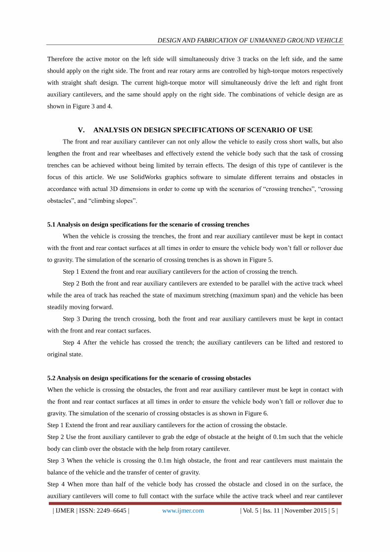
5.1 Analysis on design specifications for the scenario of crossing trenches
When the vehicle is crossing the trenches, the front and rear auxiliary cantilever must be kept in contact
with the front and rear contact surfaces at all times in order to ensure the vehicle body won’t fall or rollover due
to gravity. The simulation of the scenario of crossing trenches is as shown in Figure 5.
Step 1 Extend the front and rear auxiliary cantilevers for the action of crossing the trench.
Step 2 Both the front and rear auxiliary cantilevers are extended to be parallel with the active track wheel
while the area of track has reached the state of maximum stretching (maximum span) and the vehicle has been
steadily moving forward.
Step 3 During the trench crossing, both the front and rear auxiliary cantilevers must be kept in contact
with the front and rear contact surfaces.
Step 4 After the vehicle has crossed the trench; the auxiliary cantilevers can be lifted and restored to
original state.
5.2 Analysis on design specifications for the scenario of crossing obstacles
When the vehicle is crossing the obstacles, the front and rear auxiliary cantilever must be kept in contact with
the front and rear contact surfaces at all times in order to ensure the vehicle body won’t fall or rollover due to
gravity. The simulation of the scenario of crossing obstacles is as shown in Figure 6.
Step 1 Extend the front and rear auxiliary cantilevers for the action of crossing the obstacle.
Step 2 Use the front auxiliary cantilever to grab the edge of obstacle at the height of 0.1m such that the vehicle
body can climb over the obstacle with the help from rotary cantilever.
Step 3 When the vehicle is crossing the 0.1m high obstacle, the front and rear cantilevers must maintain the
balance of the vehicle and the transfer of center of gravity.
Step 4 When more than half of the vehicle body has crossed the obstacle and closed in on the surface, the
auxiliary cantilevers will come to full contact with the surface while the active track wheel and rear cantilever

DESIGN AND FABRICATION OF UNMANNED GROUND VEHICLE
| IJMER | ISSN: 2249–6645 | www.ijmer.com | Vol. 5 | Iss. 11 | November 2015 | 6 |
will simultaneously move the vehicle forward.
5.3 Analysis on design specifications for the scenario of climbing slopes
When the vehicle is climbing the slopes, the front and rear auxiliary cantilever must be kept in contact
with the front and rear contact surfaces at all times in order to ensure the track block to be in steady and close
contact with the ground surface such that the vehicle body won’t slide due to the slope angle. The simulation of
the scenario of climbing slopes is as shown in Figure 7.
Step 1 Extend the front and rear auxiliary cantilevers for the action of climbing slope based on leverage.
Step 2 Use the front auxiliary cantilever to grab the edge of slope, and then rotate the cantilever to align
the vehicle body in parallel with the front auxiliary cantilever before the upward movement.
Step 3 Both the front and rear auxiliary cantilevers are extended and in parallel with active track wheel
such that the track area has reached the maximum stretching (maximum span) state.
Step 4 When the vehicle is getting close to the surface, the front cantilever will come to full contact with
the surface while the active track wheel and rear cantilever will simultaneously move the vehicle forward.
VI. STRESS ANALYSIS OF THE VEHICLE
In this research we use ANSYS computer-aided analysis software to simulate the static analysis on the
main frame structure of vehicle body. Simplified model parameter settings have been adopted in this research,
and the concept of simplification is explained as the followings: during the simplification process, parts are
divided into two categories as 1) main structure parts as the parts to withstand stress, and 2) general assembly
parts (non-structural parts) as the parts without withstanding any stress in order to achieve the goal of model
simplification. Since this analysis is regarded as mechanical analysis, we only keep main structural parts for the
settings of structural grid and boundary conditions, and we also observe and analyze the stress values and
displacement along X-direction, Y-direction and Z-direction in order to determine whether or not the material
strength and the structure have been damaged.
6.1 Stress analysis of mainframe structure
The aluminum alloy 6061-T6 is selected as the material for mainframe structure with maximum load
capacity at 490N. The boundary conditions are: one side of the mainframe is fixed at the inner hole while the
average stress distribution on the surface of inner hole on the other side of mainframe is 490N. The Young’s
modulus of the aluminum alloy material is 69Gpa, Poisson’s ratio is 0.3, and the density is 2.7 (g/cm3). Based
on the analysis results, when the mainframe structure is withstanding downward force as shown in Figure 8, the
overall deformation is 0.378586 mm and the maximum displacement took place at the edge of outer diameter.
The analysis results have been summarized in Table 1 showing that the deformation along the X direction is
0.029788 mm, the deformation along the Y direction is 0.378541 mm, and the deformation along the Z direction
is 0.002675 mm. So the majority of structural deformation takes place along the Y direction and this 0.378541
mm deformation took place at the edge of side plate at the force-bearing end. The mainframe structure has been
withstanding the stress of 9.079Mpa as shown in Figure 9 without causing any structural damage. Stresses along

DESIGN AND FABRICATION OF UNMANNED GROUND VEHICLE
| IJMER | ISSN: 2249–6645 | www.ijmer.com | Vol. 5 | Iss. 11 | November 2015 | 7 |
all directions have not been surpassing the yield strength of aluminum alloy 6061-T6 at 270Mpa such that from
the analysis results we can conclude that the stress applied to the mainframe structure should be within the
safety range.
6.2 Stress analysis of auxiliary cantilever structure
The aluminum alloy 6061-T6 is selected as the material for auxiliary cantilever structure with maximum
load capacity at 490N. The boundary conditions are: the large end of the auxiliary cantilever is fixed at the inner
hole while the average stress distribution on the surface of upper edge of inner hole on both sides of auxiliary
cantilever is 490N. The Young’s modulus of the aluminum alloy material is 69Gpa, Poisson’s ratio is 0.3, and
the density is 2.7 (g/cm3). Based on the analysis results, when the mainframe structure is withstanding
downward force as shown in Figure 10, the overall deformation is 0.811756 mm and the maximum
displacement took place at the edges of both sides of front end of auxiliary cantilever. The analysis results have
been summarized in Table 2 showing that the deformation along the X direction is 0.032176 mm, the
deformation along the Y direction is 0.811227 mm, and the deformation along the Z direction is 0.101866 mm.
So the majority of structural deformation takes place along the Y direction and this 0. 811227 mm deformation
took place at the edges of both sides of front end of auxiliary cantilever. The main structure has been
withstanding the stress of 45.071Mpa as shown in Figure 11 without causing any structural damage. Stresses
along all directions have not been surpassing the yield strength of aluminum alloy 6061-T6 at 270Mpa such that
from the analysis results we can conclude that the stress applied to the auxiliary cantilever structure should be
within the safety range.
6.3 Stress analysis of active gear structure
The aluminum alloy 6061-T6 is selected as the material for active gear structure with maximum load
capacity of single side active gear structure at 490N. The boundary conditions are: the active gear is fixed at the
inner hole while the average stress distribution on the surface of active gear is 490N. The Young’s modulus of
the aluminum alloy material is 69Gpa, Poisson’s ratio is 0.3, and the density is 2.7 (g/cm3). Based on the
analysis results, when the active gear structure is withstanding downward force as shown in Figure 12, the
overall deformation is 0.003341 mm and the maximum displacement took place at the edge of outer diameter.
The analysis results have been summarized in Table 3 showing that the deformation along the X direction is
0.778E-3 mm, the deformation along the Y direction is 0.806E-4 mm, and the deformation along the Z direction
is 0.001896 mm. So the majority of structural deformation takes place along the Z direction and this 0. 001896
mm deformation took place at the edge of outer diameter. The main structure has been withstanding the stress of
3.229Mpa as shown in Figure 13 without causing any structural damage. Stresses along all directions have not
been surpassing the yield strength of aluminum alloy 6061-T6 at 270Mpa such that from the analysis results we
can conclude that the stress applied to the active gear structure should be within the safety range.

DESIGN AND FABRICATION OF UNMANNED GROUND VEHICLE
| IJMER | ISSN: 2249–6645 | www.ijmer.com | Vol. 5 | Iss. 11 | November 2015 | 8 |
VII. CONCLUSIONS
In this article we have accumulated numerous relevant design experiences and knowledge, and the R&D
achievements with respect to the designed ground unmanned vehicle can be summarized as the followings:
In this article we search, classify and analyze existing patents and literatures in order to facilitate speedy
penetration into the R&D and design of UGV.
We use the Solid Works graphics software to establish the 3D models of unmanned vehicle (including
diagrams of all parts and assembly diagram) leading to great contribution to the establishment, modification,
assembly, and interference checking of models while meeting the requirements of design criteria.
We use ANSYS computer-aided analysis software to conduct our analysis, and the results have shown that
the maximum stress applied to the unmanned vehicle structure designed by us has been within the safety range.
The actual machine test has proven the designed vehicle can adapt to complicated and varying terrains while
accomplishing preset objectives of crossing 0.6 m wide trench, crossing 0.1m high obstacle, and climbing up the
30 degree slope.
In the future we can utilize the breakthrough AI technology which has been developed over the years in
conjunction with modularization integration approach in order to develop the highly adaptive unmanned vehicle
with the capability of immediate terrain detection.
REFERENCES
[1]. Jien-Ren Ding, 3D motion simulation and dynamic analysis of tracked vehicle, Master Thesis, Master Program of
Mechanical Engineering, Da-Yeh University, 2001.
[2]. Rong-Bin Hu, dynamic analysis of torsion bar of armored vehicle carrier system, Master Thesis, Master Program
of Weapon System Engineering, Chung Cheng Institute of Technology, Taoyuan, 1988.
[3]. Kun-See Wu, Computer-aided Engineering Analysis of Vehicle Dynamic Driving Quality, Master Thesis, Master
Program of Mechanical Engineering, National Pingtung University of Science and Technology, 2002.
[4]. Hsin-ShenPeng, Vibration Analysis of the Optimization of Suspension and Transmission Shaft Integral
Components of Vehicle Chassis, Master Thesis, Master Program of Mechanical Engineering, National Central
University, Taoyuan, 2000.
[5]. Jian-Wei Lin, Application of Self-Tuning Adaptive Control for Active Vehicle Suspension System, Master Thesis,
Master Program of Mechanical Engineering, National Taiwan University of Science and Technology, Taipei, 2001.
[6]. Thomas D. Gillespie, translated and edited by Shiao-Tseng Lin, Vehicle Movement Mechanics, Science Books,
2002.
[7]. Chinese National Standards (CNS), Glossary of terms relating to automobiles stability and controllability,
published by Central Standard Bureau of Ministry of Economic Affairs, 1983.
[8]. Jing-Hsiung Huang, Modern Automobile Chassis, CHWA, 1995.
[9]. Revised by Masakazu Iguchi, Shinji Yamakawa, Encyclopedia of Latest Automotive Technologies, Asakura
Bookstore, Tokyo, 1993.
[10]. Tom Clancy, translated and edited by Shen-Hsiung Chuang, Tour of Armored Cavalry Regiment, Starlight
Publishing Co., 1995.

DESIGN AND FABRICATION OF UNMANNED GROUND VEHICLE
| IJMER | ISSN: 2249–6645 | www.ijmer.com | Vol. 5 | Iss. 11 | November 2015 | 9 |
[11]. Tim Ripley, translated and edited by Wei-Chiang Chou, Modern U.S. Army, Rye Field Publishing Co., 1997.
[12]. J. Y. Wang, “Theory of Ground Vehicles.”, 1993.
[13]. Rong-Bin Hu, dynamic analysis of torsion bar of armored vehicle carrier system, Master Thesis, Master Program
of Weapon System Engineering, Chung Cheng Institute of Technology, Taoyuan, 1988.
[14]. Jen-Yue Lin, Research and Analysis of Design Parameters Optimization of Tracked Vehicle Carrier System, Master
Thesis, Master Program of Weapon System Engineering, Chung Cheng Institute of Technology, Taoyuan, 1999.
[15]. She-Ming Chang, Calculation Model for Power System Matching and Performance Evaluation of Armored Vehicle,
Master Thesis, Master Program of Weapon System Engineering, Chung Cheng Institute of Technology, Taoyuan,
2000.
[16]. http://www.atc.army.mil (U.S.Army website).
[17]. Second Generation Combat Vehicle, translated and edited by Chin-Chung Yao, Rye Field Publishing Co., 1996.
[18]. Modern Weapons and Wars, Chung-Lie Song of Knowledge is Power Book Series Group, 1994.
[19]. Wei-Hsin Liu, Mechanical Optimization Design, CHWA, 1996.
[20]. Yue-Liang Lai, Chi-How Lin, Chung-Yo Hsieh, ANSYS Computer-aided Engineering Analysis, Scholars Books
Co., Ltd., 2000.
Summary of Graphics and Charts
Figure 1 The originally invented mechanism filed by iRobot (Patent No. 06668951)
Figure 2 The illustration of separated active wheel and auxiliary cantilever active wheel.

DESIGN AND FABRICATION OF UNMANNED GROUND VEHICLE
| IJMER | ISSN: 2249–6645 | www.ijmer.com | Vol. 5 | Iss. 11 | November 2015 | 10 |
Figure 3 Vehicle design assembly diagram (I)
Figure 4 Vehicle design assembly diagram (II)
Figure 5 Simulation drawings of trench crossing scenario
Movement direction

DESIGN AND FABRICATION OF UNMANNED GROUND VEHICLE
| IJMER | ISSN: 2249–6645 | www.ijmer.com | Vol. 5 | Iss. 11 | November 2015 | 11 |
Figure 6 Simulation drawings of obstacle crossing scenario
Figure 7 Simulation drawings of slope climbing scenario
Fixed end
Withstanding
upward load
Maximum
deformation

DESIGN AND FABRICATION OF UNMANNED GROUND VEHICLE
| IJMER | ISSN: 2249–6645 | www.ijmer.com | Vol. 5 | Iss. 11 | November 2015 | 12 |
Figure 8 Maximum displacement of the mainframe structure
Figure 9 Stress distribution of the mainframe structure
Figure 10 Maximum displacement of the auxiliary cantilever structure
Figure 11 Stress distribution of auxiliary cantilever structure
Fixed end
Withstanding
upward load
Maximum
stress
Maximum
deformation
Withstanding upward load
Fixed at the inner hole
Maximum
stress
Withstanding
upward load
Fixed at the
inner hole

DESIGN AND FABRICATION OF UNMANNED GROUND VEHICLE
| IJMER | ISSN: 2249–6645 | www.ijmer.com | Vol. 5 | Iss. 11 | November 2015 | 13 |
Figure 12 Maximum displacement of active gear structure
Figure 13 Stress distribution of active gear structure
Table 1 Deformation of mainframe structure
Deformation
unit
Maximum total
deformation
X direction Y direction Z direction
(mm) 0.378586 0.029788 0.378541 0.002675
Table 2 Deformation of auxiliary cantilever structure
Deformation
unit
Maximum total
deformation
X direction Y direction Z direction
(mm) 0.811756 0.032176 0.811227 0.101866
Table 3 Deformation of active gear structure
Deformation
unit
Maximum total
deformation
X direction Y direction Z direction
(mm) 0.003341 0.788E-3 0.806E-4 0.001896
Withstanding downward load
Maximum deformation
Fixed at the
inner hole
Maximum
stress Withstanding
downward load
Fixed at the
inner hole