Design and Fabrication of an Aerostat for Wireless ...ltasys/WEBPAGES/PDFs/Amol.pdf · American...
14
American Institute of Aeronautics and Astronautics 1 Design and Fabrication of an Aerostat for Wireless Communication in Remote Areas Vinit N. Gawande * , Prakhil Bilaye * , Amol C. Gawale † , Rajkumar S. Pant ‡ and Uday B. Desai § Indian Institute of Technology Bombay, Mumbai, Maharashtra, 400076 This paper provides details of an endeavour to study the efficacy of aerostats as a platform for cost-effective wireless communication as an alternative to fixed tower networks, to fill the digital devoid of the communication in sharing the knowledge and information from urban societies to sparsely populated rural areas in India. The main design intent was to develop a platform to hold wireless communication equipment at an altitude of 100-250 m AGL, so that last-mile wireless connectivity could be established over a radius of around 10 km from the aerostat launch site. The paper provides details of a methodology for design and performance analysis of the aerostat, and examining the sensitivity of various operational parameters. The methodology is a systematic collation of various design approaches and concepts, which were examined during the ongoing design and field trial exercises related to remotely controlled airships and aerostats at the Lighter-Than-Air Systems Laboratory of the institute. The various design decisions were driven by the availability of local materials for different components. The paper describes the design process followed, and fabrication techniques employed for developing experimental aerostat prototypes. Nomenclature AGL = Above Ground Level CB = Centre of Buoyancy C DV = Volumetric drag coefficient CG = Centre of gravity C p = Pressure coefficient d = Diameter of the envelope [m] D = Drag on the envelope [N] GNVR = GNV Rao envelope Profile for aerostat l = Length of the envelope [m] ISA = International Standard Atmosphere LTA = Lighter Than Air LOS = Line of Sight net Lift = Net lift [kg] LMDS = Local Multipoint Distribution System MSL = Mean Sea Level NPL = National Physical Laboratory PADS = Procedure for Aerostat Design and Sizing Pu LTA = Percentage purity of the contained gas [%] Pr aero = Pressure due to aerodynamic loading (kg/m 2 ) Pr hydro = Pressure due to Dynamic Pressure loading (kg/m 2 ) Re = Reynolds number * Postgraduate Student, Department of Electrical Engineering, Non Member † Project Engineer, Department of Electrical Engineering, Non Member ‡ Associate Professor, Aerospace Engineering Department, Member § Professor, Electrical Engineering Department, Non Member
Transcript of Design and Fabrication of an Aerostat for Wireless ...ltasys/WEBPAGES/PDFs/Amol.pdf · American...
American Institute of Aeronautics and Astronautics
1
Design and Fabrication of an Aerostat for Wireless Communication in Remote Areas
Vinit N. Gawande*, Prakhil Bilaye*, Amol C. Gawale†, Rajkumar S. Pant‡ and Uday B. Desai§ Indian Institute of Technology Bombay, Mumbai, Maharashtra, 400076
This paper provides details of an endeavour to study the efficacy of aerostats as a platform for cost-effective wireless communication as an alternative to fixed tower networks, to fill the digital devoid of the communication in sharing the knowledge and information from urban societies to sparsely populated rural areas in India. The main design intent was to develop a platform to hold wireless communication equipment at an altitude of 100-250 m AGL, so that last-mile wireless connectivity could be established over a radius of around 10 km from the aerostat launch site. The paper provides details of a methodology for design and performance analysis of the aerostat, and examining the sensitivity of various operational parameters. The methodology is a systematic collation of various design approaches and concepts, which were examined during the ongoing design and field trial exercises related to remotely controlled airships and aerostats at the Lighter-Than-Air Systems Laboratory of the institute. The various design decisions were driven by the availability of local materials for different components. The paper describes the design process followed, and fabrication techniques employed for developing experimental aerostat prototypes.
Nomenclature AGL = Above Ground Level CB = Centre of Buoyancy CDV = Volumetric drag coefficient CG = Centre of gravity Cp = Pressure coefficient d = Diameter of the envelope [m] D = Drag on the envelope [N] GNVR = GNV Rao envelope Profile for aerostat l = Length of the envelope [m] ISA = International Standard Atmosphere LTA = Lighter Than Air LOS = Line of Sight
netLift = Net lift [kg] LMDS = Local Multipoint Distribution System MSL = Mean Sea Level NPL = National Physical Laboratory PADS = Procedure for Aerostat Design and Sizing PuLTA = Percentage purity of the contained gas [%] Praero = Pressure due to aerodynamic loading (kg/m2) Prhydro = Pressure due to Dynamic Pressure loading (kg/m2) Re = Reynolds number
* Postgraduate Student, Department of Electrical Engineering, Non Member † Project Engineer, Department of Electrical Engineering, Non Member ‡ Associate Professor, Aerospace Engineering Department, Member § Professor, Electrical Engineering Department, Non Member
American Institute of Aeronautics and Astronautics
2
SAC = Space Application Centre Ve = Enveloppe Volume [m3] V = Wind speed [m/s] ρa
air, ρaLTA = Air density and Contained gas at off standard design pressure altitude [kg/m3]
I. Introduction of the Concept odern day technology lays emphasis on development of platforms that support rapid exchange of data. A major step in this direction has been the introduction of Internet. Over the last decade, a large chunk of the
urban population has especially benefited from this. However, in many developing nations, the rural population is still devoid of internet connectivity. While poor infrastructure and high installation costs are obvious reasons behind the digital divide, the intrinsic property of rural areas to be sparsely populated further complicates the problem. Wired connection to each and every household becomes an economically unviable option.
A novel solution to this problem based on latest wireless technology was proposed, which aims to employ wireless bridges that can span distances to the tune of 10 km. The basic approach is to mount antennas (typically directional) on a high tower which is then connected to the wireless bridge. These antennas now look at client side antennas through LOS connectivity for internet access. It is the cost of high towers (50 to 100 meters) at the base station which makes deployment of wireless networks (say WiFi) expensive. To overcome the cost barrier of high towers, use of tethered aerostats has been proposed and also in execution, which will reach heights exceeding 100 meters in the air to ensure that disturbance free LOS is available. This system aims to connect the far-flung rural communities to the urban areas, for knowledge and information sharing, using a mechanism that is easily re-locatable, and requires very low expenditure on fixed infrastructure, when compared to other options.
Grace1 et al. have discussed the application of High Altitude Platforms operating in the stratosphere, 20 to 22 km above the ground for meeting the ever increasing demand for capacity for future generation multimedia applications, by utilizing the frequency allocations in the mm wave bands e.g. those specified for LMDS. These frequency bands are capable of delivering considerably higher data rate services, due to the larger frequency allocations available. However, in these frequency bands, signals experience high attenuation due to LOS obstructions, and also to rain, which requires appropriate link margins to be used in order to guarantee availability and quality of service. HAPs are ideal in tackling both these problems effectively, i.e., LOS obstructions and rain attenuation. Such platforms have the potential capability to serve a large number of users, situated over a large geographical area, using considerably less communications infrastructure than that required if delivered by a terrestrial network.
Several patents have also been granted recently for innovative applications of aerostats. For instance, Knoblach and Frische2 have proposed the creation of an airborne constellation with a system of individual lighter-than-air platforms spaced apart above a contiguous geographical area within a predetermined altitude range, so that proper LOS of coverage of the geographic area is provided. Each of the LTA platforms further includes a signal transmitting device attached to the enclosure by which the signals from the platform may be transmitted to the contiguous area. In another patent, a distributed elevated Radar antenna system has been proposed by Halsey and Boschma3, which is an airborne radar antenna system for detecting a target in a volume that includes a tethered aerostat and an antenna that is supported above ground by the aerostat. The aerostat-based antenna is used for transmitting and receiving a radar beam into the volume to detect the target. Additionally, the system includes a ground-based transmitter that generates a beacon signal which monitors the antenna configuration at the aerostat. The current system is also one of the possible innovative applications of LTA systems technology, and is quite similar to these two systems.
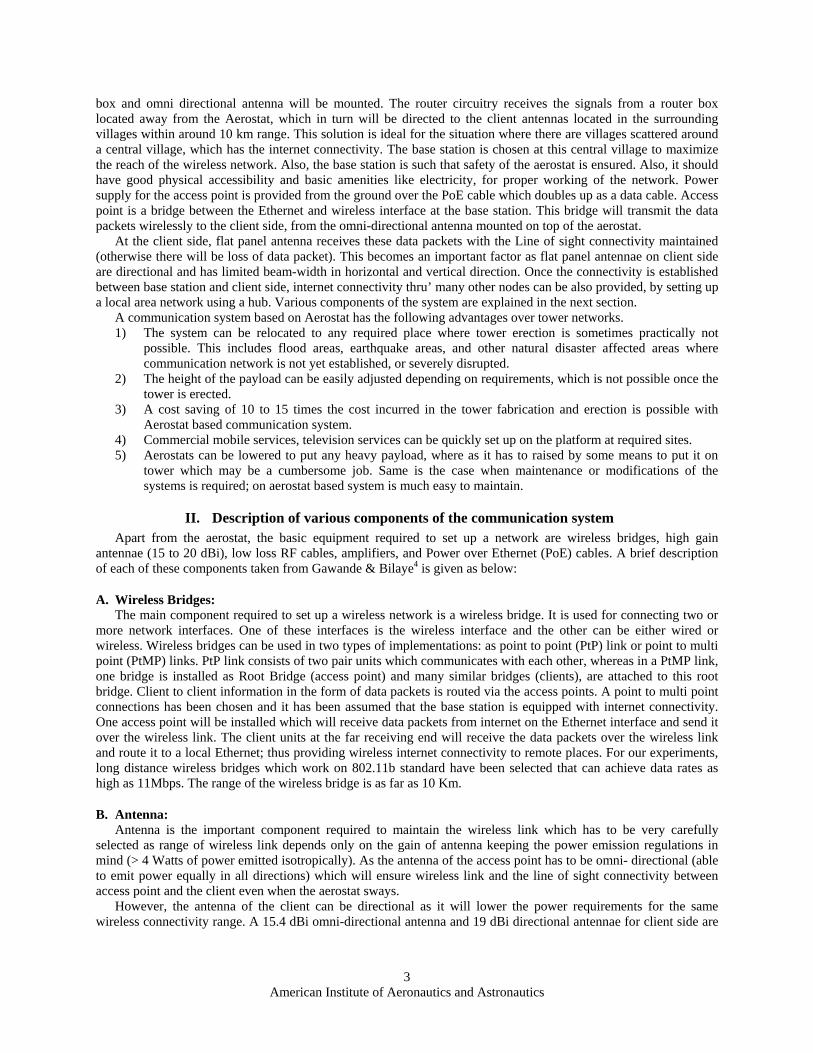
A schematic diagram of the proposed system is shown in Fig. 1. Depending on the geography of the area, aerostat is raised centrally to an altitude of around 50-200 m AGL on which a payload consisting of a router
M
Figure 1. Conceptual sketch of the Aerostat based wireless communication system (Ref. 4)
American Institute of Aeronautics and Astronautics
3
box and omni directional antenna will be mounted. The router circuitry receives the signals from a router box located away from the Aerostat, which in turn will be directed to the client antennas located in the surrounding villages within around 10 km range. This solution is ideal for the situation where there are villages scattered around a central village, which has the internet connectivity. The base station is chosen at this central village to maximize the reach of the wireless network. Also, the base station is such that safety of the aerostat is ensured. Also, it should have good physical accessibility and basic amenities like electricity, for proper working of the network. Power supply for the access point is provided from the ground over the PoE cable which doubles up as a data cable. Access point is a bridge between the Ethernet and wireless interface at the base station. This bridge will transmit the data packets wirelessly to the client side, from the omni-directional antenna mounted on top of the aerostat.
At the client side, flat panel antenna receives these data packets with the Line of sight connectivity maintained (otherwise there will be loss of data packet). This becomes an important factor as flat panel antennae on client side are directional and has limited beam-width in horizontal and vertical direction. Once the connectivity is established between base station and client side, internet connectivity thru’ many other nodes can be also provided, by setting up a local area network using a hub. Various components of the system are explained in the next section.
A communication system based on Aerostat has the following advantages over tower networks. 1) The system can be relocated to any required place where tower erection is sometimes practically not
possible. This includes flood areas, earthquake areas, and other natural disaster affected areas where communication network is not yet established, or severely disrupted.
2) The height of the payload can be easily adjusted depending on requirements, which is not possible once the tower is erected.
3) A cost saving of 10 to 15 times the cost incurred in the tower fabrication and erection is possible with Aerostat based communication system.
4) Commercial mobile services, television services can be quickly set up on the platform at required sites. 5) Aerostats can be lowered to put any heavy payload, where as it has to raised by some means to put it on
tower which may be a cumbersome job. Same is the case when maintenance or modifications of the systems is required; on aerostat based system is much easy to maintain.
II. Description of various components of the communication system Apart from the aerostat, the basic equipment required to set up a network are wireless bridges, high gain
antennae (15 to 20 dBi), low loss RF cables, amplifiers, and Power over Ethernet (PoE) cables. A brief description of each of these components taken from Gawande & Bilaye4 is given as below:
A. Wireless Bridges: The main component required to set up a wireless network is a wireless bridge. It is used for connecting two or
more network interfaces. One of these interfaces is the wireless interface and the other can be either wired or wireless. Wireless bridges can be used in two types of implementations: as point to point (PtP) link or point to multi point (PtMP) links. PtP link consists of two pair units which communicates with each other, whereas in a PtMP link, one bridge is installed as Root Bridge (access point) and many similar bridges (clients), are attached to this root bridge. Client to client information in the form of data packets is routed via the access points. A point to multi point connections has been chosen and it has been assumed that the base station is equipped with internet connectivity. One access point will be installed which will receive data packets from internet on the Ethernet interface and send it over the wireless link. The client units at the far receiving end will receive the data packets over the wireless link and route it to a local Ethernet; thus providing wireless internet connectivity to remote places. For our experiments, long distance wireless bridges which work on 802.11b standard have been selected that can achieve data rates as high as 11Mbps. The range of the wireless bridge is as far as 10 Km.
B. Antenna: Antenna is the important component required to maintain the wireless link which has to be very carefully
selected as range of wireless link depends only on the gain of antenna keeping the power emission regulations in mind (> 4 Watts of power emitted isotropically). As the antenna of the access point has to be omni- directional (able to emit power equally in all directions) which will ensure wireless link and the line of sight connectivity between access point and the client even when the aerostat sways.
However, the antenna of the client can be directional as it will lower the power requirements for the same wireless connectivity range. A 15.4 dBi omni-directional antenna and 19 dBi directional antennae for client side are

American Institute of Aeronautics and Astronautics
4
in use. These antennae will operate in the frequency range of 2.4-2.5GHz and have the bandwidth of 100 MHz. The directional antennae have limited horizontal and vertical beam-width.
C. RF Cables: This cable connects the antenna with the wireless bridge. This link operates at a very high frequency (2.4 GHz)
so the cable needs to be low loss cables. According to an estimate, there is a 6dB loss per 40 feet length of cable. To minimize this loss, both the antenna and bridge have been mounted on the aerostat.
D. Power over Ethernet Cable (PoE): The access point which is mounted on the aerostat rises up to 50m height. Power over Ethernet cable are used to
supply power as well as data connection to the bridge this eliminates the need for two separate cables. This results in decrease of the total payload to be carried, and hence the volume of the Aerostat system
III. Aerostat Design Methodology The Depending on the payload, range of surveillance, and operational time at station, aerostats have been
launched to an operating altitude of around 4600 m from sea level. As per published literature from Ref. 5, aerostats have been successfully deployed by commercial companies to carry payload such as Surveillance radars of all sizes and capabilities, Signal Intelligence (SIGINT) collection equipment, Gyro-stabilized daylight, low-light level and infra-red video cameras, Direct television broadcast and relay, FM radio broadcast and relay, VHF/UHF, Ground Control Intercept (GCI) and microwave communications, and Environmental monitoring equipment.
Based on the preliminary work carried out by Gupta & Pant6, and Raina & Gawale7, a methodology for initial sizing and conceptual design of an aerostat system has been developed to arrive at the required geometrical parameters and detailed mass breakup of an aerostat system, given the values of some operation, configuration, and performance related parameters. This methodology implements spread sheet form of MS-EXCEL™ and named as PADS.
PADS accepts all the input parameters, constant parameters, and some geometrical and operation related options such as envelope profile selection, gas pressure management by ballonets or symmetrically expandable elastic strip, and type of LTA gas used. The objective behind providing this facility for selection of optional parameters was to make the methodology more flexible and adaptive for any future modification in the aerostat system, and also to make sensitivity analyses much more comprehensive.
In an aerostat the geometry of the envelope has a profound effect on its aerodynamic characteristics, and hence on the stability and payload carrying ability. Some standard shapes of the aerostat envelopes exist and their profiles were incorporated in the input part of the PADS.
E. Various modules in PADS PADS is designed in a modular
fashion and contains 48 spread sheets with separate modules that cover the calculations related to LTA gas properties in the atmosphere, and sizing of envelope, petal, tether and fins. The design procedure is based on the flow chart shown in Fig. 2. It also has modules that carry out calculations related to LOS error angle calculation, pivot and safety-system attachment. The fabrication process plans, including that of a small winch are worked out and cost calculations are carried out. Design flow is described in a modular way which Figure 2. Design methodology flow chart (Ref. 7)

American Institute of Aeronautics and Astronautics
5
enables to understand the contribution of each module for the design and sizing in subsequent steps.
F. Database and Options for Design Initialization Database and Options module contains various information and options required to carry out specific looped task
to size major components of the aerostat. This mainly includes options like choice of contained gas viz., Helium, Hydrogen; choice of envelope shape viz., NPL, GNVR, SAC with normalized coordinates, and fin dimensions; tether CD calculation chart for various Reynolds number based on the work carried by Wright8; tether material and specification up to 2 km AGL. Strength properties of envelope material are also added that includes breaking strength in warp and weft directions, He/ H2 permeability rate, and surface density. There is scope for adding various options and database in the same module in future.
G. Design Requirements The main module is the heart of PADS, all the inputs and options can be selected to perform design and analysis.
A case as in the Table 1 shows the structure of the spread sheet for input parameters. PADS is designed for SI units.
Table 1: Sample inputs of Main module of the PADS (Ref. 7) Input Parameters SI Unit Typical Value
Payload [kg] 7.00 Floating Altitude (From Sea Level) [m] 740.81
Spot Altitude from Sea Level [m] 560.00 Design Wind Speed [m/s] 15.00
Off Standard Temperature [oC] 20.00 Operational Time [days] 15.00
Diurnal Temperature range [oC] 10.00 Free Lift Permissible % 15.00
Permissible Reduction in Altitude ±DH 5.00 Constant Parameters
Contained Gas Initial Purity [%] 99.50 Option for Envelope Material (PVC-1, Other-2) PVC 1.00 Rate of Gas Permeability thru Envelope fabric [ltr/m2/day] 2.50
PoE Cable Specific Length [kg/m] 0.04 Low Loss Cable Specific Length [kg/m] 0.00
Elastic Strip Specific Length [kg/m] 0.02 Available PVC Fabric density [kg/m2] 0.21
Permissible Blow by and Excess Length for all the cables Design altitude AGL % 20.00
Centre of pressure for Aerostat (0.3-0.35) [-] 0.33 Options
Profile Configuration (NPL-1, GNVR-2, SAC-3, Optimum-4, TCOM360Y-5) SAC 3
Petal Configuration (1-Single, 2-Double) Double 2 Rear Gore Petals (No. of Petals) [-] 10.00
Front Gore Petals [-] 20.00 Contained Gas (He-1, H2-2) Helium 1
Include Integrated Balloonet OR Elastic Strips (Ballonet-1,El Strip-2) El. Strip 2
American Institute of Aeronautics and Astronautics
6
Fin fabrication (Inflatable-1, Rigid outline with cover-2) 1 Mass specific length of the 0.5 inch PVC pipe gm/m 125.00
The spreadsheet like form of PADS also helps in carrying out extensive sensitivity studies. In order to resize the
aerostat of a given configuration and material for different operating conditions, only the operating parameters have to be changed. The Main module in the PADS is linked to other modules for design and sizing of various components of the Aerostat; this includes Atmosphere, Envelope, Fin, Petals for the envelope, Pivot and safety, and accessories such as winch. The required output/s from these modules is posted back to Main module.
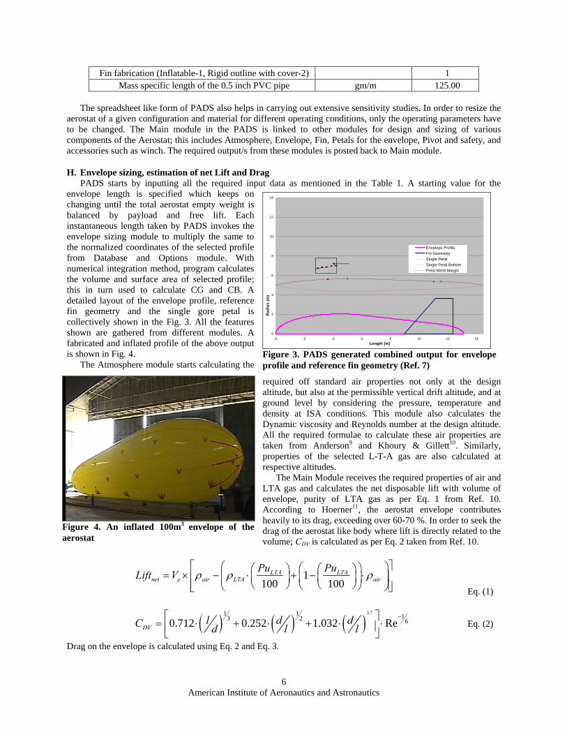
H. Envelope sizing, estimation of net Lift and Drag PADS starts by inputting all the required input data as mentioned in the Table 1. A starting value for the
envelope length is specified which keeps on changing until the total aerostat empty weight is balanced by payload and free lift. Each instantaneous length taken by PADS invokes the envelope sizing module to multiply the same to the normalized coordinates of the selected profile from Database and Options module. With numerical integration method, program calculates the volume and surface area of selected profile; this in turn used to calculate CG and CB. A detailed layout of the envelope profile, reference fin geometry and the single gore petal is collectively shown in the Fig. 3. All the features shown are gathered from different modules. A fabricated and inflated profile of the above output is shown in Fig. 4. The Atmosphere module starts calculating the
required off standard air properties not only at the design altitude, but also at the permissible vertical drift altitude, and at ground level by considering the pressure, temperature and density at ISA conditions. This module also calculates the Dynamic viscosity and Reynolds number at the design altitude. All the required formulae to calculate these air properties are taken from Anderson9 and Khoury & Gillett10. Similarly, properties of the selected L-T-A gas are also calculated at respective altitudes.
The Main Module receives the required properties of air and LTA gas and calculates the net disposable lift with volume of envelope, purity of LTA gas as per Eq. 1 from Ref. 10. According to Hoerner11, the aerostat envelope contributes heavily to its drag, exceeding over 60-70 %. In order to seek the drag of the aerostat like body where lift is directly related to the volume; CDV is calculated as per Eq. 2 taken from Ref. 10.
1100 100
LTA LTAnet e air LTA air
Pu PuLift V ρ ρ ρ⎡ ⎤⎛ ⎞⎛ ⎞⎛ ⎞ ⎛ ⎞= × − ⋅ + − ⋅⎢ ⎥⎜ ⎟⎜ ⎟ ⎜ ⎟⎜ ⎟
⎝ ⎠ ⎝ ⎠⎢ ⎥⎝ ⎠⎝ ⎠⎣ ⎦ Eq. (1)
( ) ( ) ( )2.71 1 13 2 60.712 0.252 1.032 ReDV
l d dC d l l−⎡ ⎤= ⋅ + ⋅ + ⋅ ⋅⎢ ⎥⎣ ⎦
Eq. (2)
Drag on the envelope is calculated using Eq. 2 and Eq. 3.
0
2
4
6
8
10
12
14
0 2 4 6 8 10 12 14Length (m)
Rad
ius
(m)
Envelope ProfileFin GeometrySingle PetalSingle Petal BottomPetal Weld Margin
Figure 3. PADS generated combined output for envelope profile and reference fin geometry (Ref. 7)
Figure 4. An inflated 100m3 envelope of the aerostat

American Institute of Aeronautics and Astronautics
7
22 31
2aair DVD v V Cρ= ⋅ ⋅ ⋅ ⋅ Eq. (3)
This value is used in tether module along with other parameters for calculating the expected blow by which is explained later.
I. Internal Over Pressure Estimation In order to maintain positive pressure inside the envelope, three main loadings are considered to estimate the
internal over pressure (∆P) viz., the loading due to dynamic pressure, aerodynamic loading, and hydrostatic pressure as suggested by Gupta & Malik12. A brief description of these three components of the module is as given below. Loading due to dynamic pressure which acts on the front portion of the aerostat envelope and tries to make a depression on the envelope surface, its diameter depends on the region of highly stressed area which is normally 7 to 9 % of the envelope length. To maintain the shape of the envelope, the internal pressure is kept slightly higher than dynamic pressure, normally 15% as suggested by Gupta & Malik12 as per Eq. 4.
21Pr 1.152
adyna air vρ⎛ ⎞= ⋅ ⋅ ⋅⎜ ⎟
⎝ ⎠ Eq. (4)
Aerodynamic loading results from applying the stability conditions to the aerostat. Aerostat is operated at certain angle of attack, (normally 2 to 2.5 degrees) which results in aerodynamic loading. Coefficient of pressure, as observed normally for such envelope profiles is in the range of 0.30 to 0.35 from the leading edge, but normally for such shapes, it is assumed at the maximum diameter (Ref.12). Eq. 5 is used for calculating the pressure due to this loading.
21Pr2
aaero p airC vρ⎛ ⎞= ⋅ ⋅ ⋅⎜ ⎟
⎝ ⎠ Eq. (5)
Hydrostatic pressure: This is due to the difference between the height of the top and bottom of aerostat and could be quite substantial of the aerostat diameter in large. The hydrostatic pressure as observed at mean centerline axis of the envelope is calculated at maximum diameter using Eq. 6.
( )Pr2
a ahydro air LTA
dgρ ρ= − ⋅ ⋅ Eq.(6)
The sum of pressure due to these three loadings gives the total required internal pressure. Since the aerostat envelope diameter is more than twenty times of the thickness of the material; it can be
considered as a very thin shell and hence hoop stress is calculated in terms of the circumferential unit load as shown in Eq. 7.
2cdpσ = ∆ ⋅ Eq. (7)
Normally, this value is expressed in terms of kg/5cm of circumferential length of maximum diameter of envelope material fiber. This gives the allowable load that the envelope material fiber of 5 cm length, aligned in circumferential fashion can bear. The stress calculated using Eq. 7 is then compared with the allowable stress value of the selected fabric stored in the database. A factor of safety of 4 (four) has normally been kept in selection of envelope fabric. This is required to take care of the inaccuracies in the calculation of diurnal temperature variations, degradation in the envelope material due to handling and prolonged exposure to atmospheric conditions, and changes in gas properties due to superheat.
J. Gore petal sizing In most of the aerostats, petals are shaped depending on size of the envelope and the available form of material.
In India, PVC rolls are usually available in a flat pipe form (double layers) of 26” width with 50 ft length. In order to achieve more accurate shape after inflation, a large number of petals are employed, if the welding length is not a constraint. For operational benefits, however, a wider material with fewer welds is always preferable from leakage view point. But lesser number of petals leads to a improper shape of the envelope, especially at the ends. Usually less petals and greater curvatures at the nose portion, lead to many folds and thus affects the shape of the envelope and also the surface quality. In order to reduce these folds, a novel technique is incorporated as suggested by Gupta & Malik12, in this technique; a single petal is divided at certain appropriate location near the maximum diameter (normally 40% from the nose) in to two symmetric petals as shown in Fig 5. Thus, a single petal remains single at

American Institute of Aeronautics and Astronautics
8
maximum diameter and subsequently at rear ends, in the region of maximum diameter, and also gets double at the nose portion to avoid folds. This split technique ensures weld joints only in front area and thus leads to minimum weld lengths.
K. Fin Sizing Fin module of PADS accepts the fin sizing parameters as soon as the selected envelope is scaled to inputted
length in envelope sizing module. PADS’s fin sizing and mass estimation are based on the reference fin area. Fin sizing is actually studied from Pant13. One of the sketches in Fig. 6, the root chord is taken on the centerline of the aerostat. Based on the selected profile from Database module, a ratio of each part of the fin geometry to the
envelope length (Root chord, Tip chord, Average half span, and the location of the trailing edge from the nose of the aerostat, to the length of the aerostat) is calculated. A linear scaling is performed on all the parameters so as to get the exact plan form geometry of the fin for the instantaneous envelope length. PADS does the fin sizing structurally for two types of fin, one is the conventional inflatable structure with symmetric airfoil and other is the framed PVC structure. NACA 0018, aerofoil cross section is commonly used as a default cross section for all the fins of various envelope profiles available in the PADS Database and Options module; Coordinates of this airfoil are extracted from Greschner14 et. al. and Mason15.
For an inflatable fin, it is necessary to join the flexible ribs made of the same material as fin to get a reasonably accurate shape of the desired aerofoil cross-section after inflation. As suggested by David16 et. al., thirteen ribs were used in the fin structure. The trailing edge can either be cut or can be aligned properly by means of harder plastic so as to maintain the contour. An inflatable fin used in one of the experimental prototype is shown in Fig. 14. Two CAD tools viz., AutoCAD2004™ and Solidworks2005™ were used for accurate rib sizing. The entire 3-D fin is firstly converted in to a flat 2-D structure by knowing the perimeter of the profile at both root and tip levels
separated by the reference half span. This gives the area which is then multiplied with surface density of cover material to get the mass of the cover. As shown in Fig. 7, width of each rib is calculated by dividing the root and tip airfoils at appropriate intervals and getting the local thickness. A margin for weld is always added to this thickness. Length of each rib is calculated directly by joining the rib from tip at one point to the corresponding point at root locations as shown in the Fig.6. Thus knowing the length and width at root and tip for each fin, surface area of all the ribs is calculated by multiplying it with the material surface density. A factor of 1.1 is used to take care of attachment of fin to the envelope and hooks for riggings.
Figure 5. Conceptual sketch of single and split petal for envelope fabrication
Figure 7. NACA 0018 as seen in inflatable fin structure at root and tip levels (Ref. 7)
Figure 6. Sketch of reference and actual fin, with dimensions, 100 m3 aerostat with attached fin

American Institute of Aeronautics and Astronautics
9
L. Tether sizing and Profile generation A tether module is developed in PADS to calculate the exact length of the combination of tether and PoE cable
required for given design altitude, wind speed, permissible blow by, and permissible free lift in the aerostat at the design altitude. This sizing is based on the method suggested by Wright17 which determines blow by of the aerostat and tether profile, given the tether tension and the tether angle at the confluence point. In this method, the tether is discretized into elements of equal lengths and starting from the confluence point, the tension and inclination angle of each subsequent element below is determined by solving for the equilibrium of forces as shown in the Fig. 8.
The tether module also predicts the profile taken by the tether at various ambient wind speeds as shown in Fig. 9 in the sensitivity studies performed by PADS. It can be seen that an increase in wind speed increases blow by. It is evident that as the tether is released, the aerostat drifts in the direction of wind due to blow-by; thus tether mass keeps on increasing leading to reduction in the free lift and also in the operating altitude. If, on the other hand,
the tether length is maintained constant, the aerostat comes down from its design altitude to balance the forces acting on it. In practice, as suggested by Gupta & Malik12, 20% extra tether is provided to take care of blow by.
Mass of the tether which is a combination of load and PoE cable is calculated by knowing the length AGL multiplied by the specific mass of the individual cable. Tether module also takes other issues in to account, such as load due to PoE cable, confluence lines to distribute the load on the envelope at various locations, and Pivot frame etc. Confluence lines’ mass is taken as 1 % of the envelope mass, and the pivot frame mass is taken after fabrication as per the payload space requirements.
M. Gas pressure management This module provides two options; the ballonets or Elastic Strips for managing the gas internal over pressure. In
case of ballonets, knowing the net positive lift at ground level, the volume of air to maintain aerostat both at ground and design altitudes is calculated. In addition to this volume, some additional air volume is calculated to maintain the platform performance at the design altitude in the effect of diurnal temperature variation at the local condition. Thus, once the total volume of air that is to be available in the ballonets is calculated, material for one or two ballonet bags which are to be kept within envelope for this air is calculated. It is obvious that before ballonet calculation, the volume calculated for the envelope is not enough to raise the payload to the design altitude. Hence, resizing is carried out by changing length with which envelope was calculated prior to the ballonet sizing.
In case of Elastic strips, sizing and mass estimation is carried out by calculating the expansion of the gas from ground to the design altitude. This varies the maximum diameter circumference which is recorded by Gas pressure management module, with some room for expansion and contraction to take care of the envelope in the diurnal temperature variations.
While launching the aerostat, envelope is filled with the lifting gas slightly less by an amount of expansion till it ascends to the design altitude which is given by the calculations in the Main module. Elastic strips maintain the tightness in the envelope. As it goes up, elastic strips allow the gas to expand and thus envelope remains tight at any altitude within the design range. Thus, knowing the volume at ground level and at design altitude, the required circumference at maximum diameter of the envelope is calculated. The difference in the circumference gives the maximum width of the elastic region, and it is maintained proportionately on front and rear portion of the maximum
Figure 8. Free body diagram of discretized elements of tether (Ref. 17)
0
20
40
60
80
100
120
0 20 40 60 80 100 120
Blowby (m)
Hei
ght (
m)
15 m/s
10 m/s
5 m/s
Figure 9. Sensitivity of tether profile with winds (Ref. 7)

American Institute of Aeronautics and Astronautics
10
diameter along the petal profile. Usually the elastic region is kept 30% of the envelope length. The dead length is the length of the elastic strip which gives maximum stretchable length more than that of required circumferential expansion. Thus, width of the maximum expandable length to take care of expansion under circumferential unit load is the sum of difference in circumference of maximum diameter at superheat volume of the envelope to ground level volume plus dead length of the strip depending on the properties. A factor of 1.5 is used for safety reasons, above dead length, knowing the fact that the envelope contraction can be managed but the expansion is quite undesirable. Further, knowing the maximum width and maximum length of the elastic region total length required, specific mass, mass of the hooks to maintain a zigzag fashion in the region and other mass of attachments are calculated.
N. Weight Estimation of Various groups Main module continues to calculate the total system mass breakdown in terms contained gas, Envelope group,
Fin group, tether group, and other accessories group. All the sub group parameters are received from respective module. Mass of the contained gas: For the particular volume that has been calculated by initializing a certain amount of length, mass of the gas filled inside is calculated by deducing the Net lift from the gross lift that is generated. Mass of Envelope Group: Envelope mass is primarily calculated as summation of total material used for envelope including weld margin and multiplied by the surface density of the material. Mass of Gas Pressure Management group: Since PADS is tuned to use ballonets only if the design altitude exceeds 500 m above MSL, the current case gives the weight for this group for elastic strips.
PADS calculates weight of rigging, hooks, patches, nose battens and Gas filling hose/port/opening in terms of the percentages of envelope as suggested (Ref. 12 & 13). Table 2 shows the mass breakup of each group and its values for the case shown in the Table 1.
Table2: Weight distribution as obtained from PADS
Group Name Sub Group Criteria / Module
output Value kg
Contained Gas - 15.18 Envelope Group 30.98
Envelope e fabric eW Sρ= ⋅ 26.3
Rigging, Hooks (24 No.) and Patches (8 No.) 0.06 eW⋅ 1.58
Nose Battens 0.1 eW⋅ 2.63 Env
elop
e
Gas Filling Hose/Port/Opening (s) 0.02 eW⋅ 0.53 Elastic Strips group 2.62
Mass of the elastic strip el s el sl ρ− −⋅ 0.91
Mass of corner hooks 10 21000 zigzagNo⋅ ⋅ 1.61
Ela
stic
stri
ps
Mass of support patch for elastic region 25 21000 el Rl −⋅ ⋅ 0.10
Mass of Fin Group 13.22 Mass of PVC Cover Fin Module* 3.65
Mass of total spars Fin Module* 0.588 Total fin Mass Fin Module* 4.24
Fin
Total Empennage mass 3 finW⋅
Tether Group 23.13
Tether t tl ρ⋅ 10.85
PoE Cable PoE PoEl ρ⋅ 8.68 Tet
her
Pivot with payload frame Fixed 3.34

American Institute of Aeronautics and Astronautics
11
Confluence lines Support Distribution Wires (1% of Envelope Mass) 0.01 eW⋅ 0.26
Other Accessories Fixed 0.70 Night Visibility System (Five Pin Lights) Fixed 0.50
GPS Receiver Fixed 0.20
Oth
er
Gross Take off Empty Mass 70.64
O. Winch Design and development: The winch is designed to arrive at a cost effective design, with main emphasis on local availability of material
and fabrication techniques. An ‘open ended approach’ was used so that it could be continuously upgraded during its development cycle. This work is taken from Sequeira18 et. al.; the specific design requirements for winch design were arrived from one of the modules described in PADS. This included parameters like expected tether tension, drum size, tether winding rate, and tether profile, power requirements for winding, Tether configuration (combination of Load and data cables, Specific weight, and diameter), minimum bending radius for cable, and length of the tether. With these inputs, main drum with collar at the ends was structurally designed with the suggestions given by Markey19, by treating it as a simply supported beam with a uniformly distributed load in terms of tether mass, and line pull as a point load. On the same lines, the complete structural design was carried out for spur gears, selection of frame cross section, provision of other drum for data cable etc. A braking system was also designed to regulate the ascending rate of aerostat with a line pull of over 70 kg. An innovative inversion of four bar link mechanism was employed for symmetrical application of the brake pressure by means of two brake shoes; which ultimately results in an effortless braking even by manual means. Fig. 10 shows a conceptual layout of this braking system. Snap shots of the winch in operation are shown in Fig. 11.
When the force P is applied at one end of the link L which is pivoted mainly at fixed link L1 drives the two links indicated by its length b1 and b2. Link b1 is directly connected whereas b2 is connected in opposite direction by means of an inversion of four bar link mechanism as shown by number 4 in the Fig. 10. Lengths a1, b1, c1 and a2, b2, c2 are so adjusted that the shoes hinged at b1 and b2 applies almost equal pressure on the drum. Thus the braking mechanism does not create any bending force on the shaft on which it is mounted.
A field trial revealed that the winch was toppling due to high line pull on the tether due to low weight of the winch. Therefore, a toppling arrester was developed and attached to the winch. This arrester has four studs housed in
a barrel which is connected to the frame of the winch at four corners. Once the winch is placed at the launch location, these studs are pierced inside the ground for firm grip and thus arrest the toppling of winch. The design of the toppling arrester takes into consideration the tether tension at drum location for all possible movement patterns of the aerostat due to ambient wind conditions. Further, the winch is powered by a single phase induction motor that drives a pulley system which in turn drives the gear pairs for rotating the main tether drum during recovery. A
Figure 10. Braking mechanism using inversion of four bar links
Figure 11. Snap shots of winch in operation during field trials
American Institute of Aeronautics and Astronautics
12
separate drum has also been provided to release and wind a data cable from the ground to a payload mounted on the aerostat which could be a communication system, still/ video camera or a data logger etc. This drum is also powered by an inversion of four bar link mechanism that draws power from main drum shaft.
P. Other Output from PADS: Apart from the outputs discussed so far, PADS also generate some other outputs which are described below. Drifting of aerostat platform results in the error in the orientation of the directional antenna at the client end
which affects the communication. If the polarization of the antenna is more than the range of the angle of orientation w.r.t. the horizontal, the communication can still be achieved. In order to know this range of orientation in vertical plane, PADS calculate the ranges by knowing the ground distance between client end and launch location at its respective altitude from datum level, normally MSL. Table 3 lists the error in the antenna orientation due to platform drift.
Table 3 : Range of orientation angle at client antenna due to platform drift (Ref. 7) Input Parameters Unit Value
Omni Antenna Height AGL from Spot [m] 120.00 Client Antenna Height AGL from client Spot [m] 10.00
Omni Antenna Height from MSL [m] 60.00 Client Antenna Height from MSL [m] 20.00
Allowable Horizontal displacement of aerostat ± [m] 10.00 Allowable Vertical displacement of Aerostat ± [m] 10.00
Straight line distance between Aerostat and Client Antenna [m] 5000.00 Calculated Parameters
Absolute Height of Router Antenna AGL [m] 180.00 Absolute Height of Client Antenna AGL [m] 30.00
Fixed angle for ideal condition w.r.t. Hoizontal line Degree 1.72 Angle for Top left position Degree 1.84
Angle for Bottom Left Position Degree 1.61 Angle for Bottom Right Position Degree 1.60
Angle for Top Right Position Degree 1.83 Maximum Range of angle change Degree 0.33
IV. Aerostat Fabrication
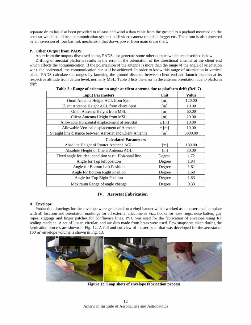
A. Envelope Production drawings for the envelope were generated on a vinyl banner which worked as a master petal template
with all location and orientation markings for all external attachments viz., hooks for nose rings, nose batten, guy ropes, riggings and finger patches for confluence lines. PVC was used for the fabrication of envelope using RF sealing machine. A set of linear, circular, and arc dies made from brass were used. Few snapshots taken during the fabrication process are shown in Fig. 12. A full and cut view of master petal that was developed for the aerostat of 100 m3 envelope volume is shown in Fig. 13.
Figure 12. Snap shots of envelope fabrication process

American Institute of Aeronautics and Astronautics
13
B. Fin The inflatable fin comprises of many ribs and thus necessitates maximum number of welded joints. For the 70
m3 aerostat fin, the total weld length for a single fin was around 68 m within a surface area of 9.52 m2. In the envelope, total weld length is over 320 m in 91.6 m2 area. Thus, fin has more than double the weld length per square meter of area (7.14 m/ m2 as compared to 3.5 m/ m2 for the Envelope). Hence, it is possible that more leakages may occur in the fin. Care has been taken in the present design to maintain the welding current for proper merging of multiple folds of the material. There is a provision of three hooks on either side of the fin at a location 2/3rd of the average half span from the root level. This is for holding the fin on the envelope from top portion. For fixing of fin at root level, a flexible flange with around 70 (Seventy) holes hardened by means of metal eyelets are attached, and same part is also attached on the envelope at same location. While attaching the fin, high strength Mylar thread is passed through both the Flanges. This arrangement is the same as the one used in Shoe laces, which results in a very firm attachment. Figure 14 shows photographs of fin under fabrication.
V. Conclusions The methodology quoted in PADS found very useful in generating the drawings for fabrication work and during the field testing of two experimental prototypes. Since PADS has a modular architecture, it is very user friendly in getting the values and graphical representation of results of individual module. Since PADS implements MS-ESCEL™ tool, sensitivity studies and graphical representation of the results can well be understood. It also provides room for continuous up gradation of the database for future use. Other features of the tool such as solver and analysis tool pack add-ins can be used for optimum design based on the available data and parameters to minimize the volume. There is still much scope to enhance PADS as a tool for complete design and analysis of aerostat and even airships with integration of CAD and CAM tools.
Figure 14: Fin fabrication pictures with rib joining and inflated fin
Figure 13. Master petal template used for the fabrication of envelope from ten petals

American Institute of Aeronautics and Astronautics
14
During the field trials, the Winch system performed as desired, the braking system positively regulated the ascending rate of the aerostat despite of tremendous line pull due to free lift which was estimated to be in excess of 70 kg ! Since the inflatable fin was designed to be attached externally, there was no provision in the fin to manage the internal over pressure in the fin during launch and diurnal temperature variation. The basic design intent of arriving at a cost effective aerostat system for wireless communication has so far been realized in two field trials.
VI. Acknowledgement Authors are very much thankful to OneWorld South Asia, an NGO, for sponsoring this project. Authors would like to show their gratitude to Prof. Ashok A. Ghatol and Prof. Madhukar Tandale of Dr. Babasaheb Ambedkar Technological University, Maharashtra and Capt. Sailesh Charbe, Incharge, Gliding Center Pune for providing logistic support during the two field trials conducted on 70m3 and 100 m3 aerostat, respectively. Authors would like to greatly appreciate the help and support rendered by Mr. Yogendra P. Jahagirdar, Director, Research Institute of Model Aeronautics, Ahmednagar in system integration during the second field trial. His valuable suggestions and guidance during the field trial helped the team in solving many integration and operation related problems.
References 1Grace, D. Daly, E., Tozer, T., Burr, A. G. and Pearce, D. A. J., “Providing multimedia communications services from high
altitude platforms”, International Journal of Satellite Communications, 2001; 19:559-580. 2Knoblach, G., M., and Frische, E., A., “Airborne Constellation of Communications Platforms and Method”, United States
Patent, Patent No. US 6,628 941 B2, filed September 30, 2003. 3Halsey, J. D., and Boschma, J., “Distributed Elevated Radar Antenna System”, United States Patent, Patent No.: US 6,677,890 B2, January 13, 2004.
4Gawande, V., Bilaye, P., “Long Distance Wireless Communication for Rural Connectivity using Tethered Aerostat”, One World South Asia Annual Regional Meeting, Agra, February 2006.
5Aerostat Specifications and Applications URL: www.tcomlp.com [cited in May 2007]. 6Gupta, P., Pant. R. S., A methodology for initial sizing and conceptual design studies of aerostats”, International Seminar on
Challenges in Aviation Technology, Integration and Operations (CATIO-05), Technical Session of 57th Annual General Meeting of The Aeronautical Society of India, December 2005.
7Raina, A. A., Gawale A. C., Pant, R. S., “Design, Fabrication and Field Testing of Aerostat system”, National Seminar on Strategic Applications of Lighter- Than- Air (L-T-A) Vehicles at Higher Altitudes, Snow and Avalanche Study Establishment, Manali, India, 12-13 October 2007 (to be published).
8Wright, J., B., “Computer Programs for Tethered-Balloon System Design and Performance Evaluation”, Report No. AFGL-TR-76-0195. Air force Geophysics Laboratories (LCB) Hanscom AFB, Massachusetts 01731, August 1976.
9Anderson, J. D., (Jr), “Introduction to Flight”, McGraw-Hill Book Company, New York, USA, 3rd ed., Chaps. 2, 3, 1989. 10Khoury, G. A., and Gillett, J. D., “Airship Technology”, Cambridge University Press, Cambridge, UK, 1st ed., 1999. 11Hoerner, S. F., “Fluid Dynamic Drag,” Midland Park, New Jersey, pp. 11.1-11.4 and pp. 44.1-44.2, 1957. 12Gupta, S., Malik, S., “Envelope details for Demo Airship”, Aerial Delivery Research and Development Establishment
(ADRDE), Agra, January 2002. 13Pant, R. S., “A methodology For Determination of Baseline Specifications of a Non-Rigid Airship”, AIAA 3rd Aviation
Technology, Integration and Operations (ATIO) Forum, November 2003, Denver, USA. 14Greschner, B., Yu.,C., Zheng, S., Zhuang, M., Wang, Z., J., and Thiele, F., “Knowledge Based Airfoil Aerodynamic and
Aero-acoustic Design”, AIAA Journal, URL: http://www.public.iastate.edu/~zjw/papers/AIAA-2005-2968.pdf [Cited in March 2006].
15Mason, W., H., “Subsonic Aerodynamics of Airfoils and Wings” URL: www.aoe.vt.edu/~mason/Mason_f/ConfigAeroSubFoilWing.pdf [cited in March 2006]
16David, C., Graham, W., Smith, T., “Inflatable and Rigidizable Wings for Unmanned Aerial Vehicles”, ILC Dover, Inc., Frederica, DE, USA. URL: http://www.ilcdover.com/products/aerospace_defense/supportfiles/AIAA2003-6630.pdf [cited March 2006]
17Wright, J., B., “Computer Programs for Tethered-Balloon System Design and Performance Evaluation”, Report No. AFGL-TR-76-0195. Air force Geophysics Laboratories (LCB) Hanscom AFB, Massachusetts 01731, August 1976.
18Sequeira, G. A., Bhandari, K., Wanjari, N., Kadam, S., Sapkal, S., “Design, Fabrication and Field testing of Winch for Aerostat”, National Seminar on Strategic Applications of Lighter- Than- Air (L-T-A) Vehicles at Higher Altitudes, Snow and Avalanche Study Establishment, Manali, India, 12-13 October 2007 (to be published).
19Michael Markey, “Handbook of Oceanographic Winch”, 3rd Ed., Wire and Cable Technology, Chap. Single Drum Winch Design. URL:http://www.unols.org/publications/winch_wire_handbook__3rd_ed/10_single_drum_winches.pdf [cited in May 2006]