ACCUMULATORS - Accumulator manufacturer -- … · Accumulator Stop Valve FHN Series

IJRET: International Journal of Research in Engineering and Technology eISSN: 2319-1163 | pISSN: 2321-7308
_______________________________________________________________________________________
Volume: 05 Special Issue: 03 | SYNERGY-2016 | Mar-2016, Available @ http://www.esatjournals.org 20
DESIGN AND FABRICATION OF AN ACCUMULATOR CONTAINER/
BATTERY PACK FOR A FORMULA STUDENT VEHICLE
Ujjwal Ashish1, Bishav Raj
2, Abhishek Kumar
3
1B.Tech (EEE), Vellore Institute of Technology, Tamil Nadu, India
2B.Tech (Mechanical), Vellore Institute of Technology, Tamil Nadu, India
3B.Tech (EEE), Vellore Institute of Technology, Tamil Nadu, India
Abstract This paper reflects the mind set and philosophy for designing the Accumulator Container for VIT University’s Formula Student
Electric Vehicle. The vehicle is made according to the rules specified by the Formula SAE (FSAE). The competition is aimed at
designing a single seat race car under certain rules and regulations. The static, dynamic and functional requirements are
established and the electrical and mechanical aspects of the battery pack are simulated. It also takes into account the Battery
Management System, Powertrain and energy requirements along with a brief description of the overall electrical system of the
vehicle.
Keywords: Battery Pack, Cell Chemistry, Cell Configuration
--------------------------------------------------------------------***----------------------------------------------------------------------
1. INTRODUCTION
Electric and hybrid vehicles depend on electrochemical
battery systems, with lithium-ion and different types of
lithium polymer chemistries which are most widely used in
terms of power density, performance and efficiency.
However, the electrical, mechanical and thermal integration
of cells into packs and packs into electrical vehicles is
paramount in order to ensure long and safe operation. The
problematic part comes into play during the integration
process. The electrical monitoring and testing of individual
cells can be done along with the thermal and cooling
analysis of the entire module within the accumulator
container. The discharge rate, cell voltages and cell
temperatures are constantly monitored by the Battery
Management System. Mechanical integrity is crucial, and
the challenge here, given the relatively high energy densities
of batteries is to minimize weight and the use of additional
support materials, whilst providing adequate support and
protection particularly in crash scenarios. The FSAE Rules
clearly dictate the guidelines related to the mechanical
configurations and stability which can be achieved by
ANSYS Simulation and Analysis.
1.1 Introduction to Tractive System
In order to maximize the battery life and efficiency, the
module design and battery management approach should be
improvised. The current drawn, discharge/charge rate and
operating and storing temperature is important in
determining the lifetime of Lithium based Cells. Batteries
are particularly intolerant to temperature extremes, with
high temperatures being encountered during high current
loading conditions such as fast charging or acceleration
transients which cause large specific internal heat generation
which in turn causes changes in the internal resistances. This
is primarily due to resistive heating in the contacts.
Chart -1: Tractive System Schematic
The schematic shows the tractive system of the vehicle
which includes the AIRs (Accumulator Isolation Relays)
used to isolate the battery pack from the entire system.
Kilovac 200 series AIRs are used for the same. The pre-
charge relay is used to prevent inrush current as soon as the
HVD (High Voltage Disconnect) completes the circuit. The
DC-DC converter is used to power up the Low Voltage and
ECU system. The car uses two Agni 95R motor in series
through a mechanical coupling. The motor has high
efficiency (about 93% maximum) giving longer running
time and less frequent battery replacement.

IJRET: International Journal of Research in Engineering and Technology eISSN: 2319-1163 | pISSN: 2321-7308
_______________________________________________________________________________________
Volume: 05 Special Issue: 03 | SYNERGY-2016 | Mar-2016, Available @ http://www.esatjournals.org 21
Table -1: Motor Specifications
Motor Manufacturer
and Type
Agni 95R PMDC
Motor
Motor principle Permanently excited
Maximum
continuous power
16kW
Peak power 30kW for 5s
Input voltage 72VAC
Nominal current 220A
Peak current 460A
Maximum torque 52N-m
Nominal torque 26N-m
Cooling method Air
Chart -2: AGNI 95R Graph for 72Volts [6]
1.2 Motor Controller
A motor controller controls the overall performance of the
motor. As shown in Figure 1, a single motor controller is
used to drive 2 AGNI 95R motors coupled in series. It
controls the voltage being supplied to the motor from the
accumulator container. The voltage supplied to the motor is
proportional to the output signal of accelerator pedal.
Kelly’s programmable PMDC motor controller provide
highly efficient, smooth and quiet controls for electric
vehicles. It uses a combination of powerful microprocessor,
MOSFET, PWM to achieve 97% efficiency. It is
regenerative braking enabled along with CAN bus module.
Table -1: Motor Controller Specifications
Motor controller type Kelly Controller
HPM14501
Maximum continuous
power 32.4KW
Maximum peak power 72kW for 1 minute
Maximum Input
voltage:
168VDC
Output voltage: 144VDC
Maximum continuous
output current:
225A
Maximum peak
current:
500A for 1 minute
Control method Analog Signal
Cooling method: Air
Auxiliary Supply
Voltage
8-30VDC
The controller reads the current reference signal and
compares it with the current that it´s on the armature circuit.
Depending on this difference, the controller supplies a
voltage that makes the armature current follow the reference
value. The controller gets its value from a potentiometer
box, used as a throttle sensor. The potentiometer range is 0-
5Kohm.
2. Cell Chemistry
For the purpose of Electric Vehicles, there are a lot of
options available as primary energy sources. The most
essential part in building an Electric Vehicle is the selection
of the Cell type or Cell Chemistry. [1] Moreover, the
optimization of the selected cell type and battery pack
configuration which in turn is determined by the powertrain
requirements, leads to better results which is only possible
through rigorous testing along with simulation and analysis.
The criterion for selection of Cell Chemistry for an Electric
Vehicle is-
High Energy Density (Wh/Kg)
High Specific Energy Density (Wh/l)
High Power Density (KW/Kg)
Fast Charging and Discharging Ability
Longer Life Cycles
Eco-Friendly

IJRET: International Journal of Research in Engineering and Technology eISSN: 2319-1163 | pISSN: 2321-7308
_______________________________________________________________________________________
Volume: 05 Special Issue: 03 | SYNERGY-2016 | Mar-2016, Available @ http://www.esatjournals.org 22
There are a lot of options available as sources for Electric
Vehicles (EV), be it VRLA(Valve Regulated Lead Acid
Battery), NiCd(Nickel Cadmium), NiMH(Nickel Metal
Hydride),C-Zn(Carbon Zinc), Li-Ion(Lithium Ion) and
LiPo(Lithium Polymer, which has more sub varieties like
Pouch and Prismatic Types).The parameters for each battery
type is given in Fig2. The parameters may differ from one
manufacturer to the other, but these values are taken as
general values.
PROPERTIES VRLA C-Zn NiMH NiCd Li-ion Li-Po
Specific Energy (Wh/Kg) 33-42 36 60-80 40-60 90-133 150-260
Specific Energy Density(Wh/l) 60-110 92 140-300 50-150 250-676 250-730
Specific Power (W/Kg) 180 10-27 250-1000 150 250-340 300-350
Life Cycles 500-800 N/A 500-2000 2000 400-1200 600-800
Cost Of Development(US$/kWh) 150 90-110 250-300 300 250 N/A
Charge-Discharge Efficiency (%) 50-95 50-60 66 70-90 80-90 80-95
Chart -3: Ragone Plot for Energy Storage
NiMH (Nickel Metal Hydride) have a moderate to higher
specific energy value but have reduced life cycles as
compared to NiCd (Nickel Cadmium). NiCd batteries have
relatively low specific energy density but are well matured
with decent specific power value. These have a good life
cycle value but are not environment friendly and hence are
not well suited for electric vehicle applications. Due to an
exponential advancement in the field of battery technology
the use VRLA (Valve Regulated Lead Acid) has been
extremely limited in the field of Electric Vehicles. The idea
behind developing an Electric Vehicle is for it to be safe,
batteries do not fit into this criteria, hence are not suitable
for EV applications.
Li-Ion is one of the fastest growing technologies in the field
of cell chemistries. [2] This is because it has extremely high
Specific Energy Density along with an impeccable Power
density value. The life cycle value can be considered to be
moderate, since it is capable of producing 80-90% charge-
discharge efficiency. The only drawback with Li-ion cell
chemistry is that it is fragile in nature and has to be
monitored by a protection circuit. Storage of the cells is also
an important point to consider. These cells are extremely
sensitive to temperature and over-heating. A Phenomenon
called “Thermal Runaway” is very commonly seen in Li-Ion
batteries. This condition is defined as situation where an
increase in temperature causes a change in the properties
and dynamics which in turn leads to further increase in
temperature, leading to an undesirable result .It is
recommended to store these type of cells in an ambient
temperature of 15°C (59°F).
Li-Polymer or Li-Po as it is generally known as,
incorporates all the properties and parameters of Li-ion
cells, with the additional advantage of it being slimmer in
geometry and light weight.[3] The significance of the word
“polymer” is that a layer of polymer is used instead of a
porous separator which is used for the exchange of ions.
There are two kinds of specifications for Li-Po batteries - 1.
Dry Type and 2. Gelled Type.
The dry type is extremely stable and can be used for hostile
applications. One major drawback with this type is poor
conductivity as compared to gelled type. The gelled polymer
electrolyte is used to enhance the capacity, conductivity and
performance of the cell. It has high specific energy density
(150-260Wh/Kg) and power density values, and its
discharge and charge rate can be easily monitored and
controlled by an efficient battery management system. The
research, analysis and testing of Li-Polymer cells have
shown excellent results and great promise. The shape and
size of the cells can be rendered and altered according the
energy requirements and design specifications. Hence Li-ion
and Li-Po are well suited for EV applications due to its
durability and high performance values under different load
conditions.

IJRET: International Journal of Research in Engineering and Technology eISSN: 2319-1163 | pISSN: 2321-7308
_______________________________________________________________________________________
Volume: 05 Special Issue: 03 | SYNERGY-2016 | Mar-2016, Available @ http://www.esatjournals.org 23
3. Transmission Calculations
The energy and power requirements for the transmission is
determined by simulating the vehicle in optimum Lap,
where in the parameters of the circuit track are modelled and
the minimum energy required to complete one lap is found
out. Similarly the energy required to complete 22 laps in the
endurance event. The calculations for the power and energy
requirements are given below-
Approximate weight of the vehicle (with driver) : 300kg
Minimum run time required : 25min
Minimum energy required to complete endurance
(Transmission Requirement) : 6960Whr
Average time required to finish one lap (Average distance
per lap/Average Speed) : 1.2km/ (52.5km/hr) = 82.82sec
Therefore, average power required (average energy/ time) :
6960Whr/ ((82.28*18)/3600) = 6960Whr/0.4114hr=
16917.8W= 16.917KW
For combination of 2 Agni 95R motors in series, power
required from 1 motor : 16.917KW/2= 8.458kW
Corresponding to 8.458 kW at 72V current from the motor
characteristics is nearly 117.47 A, therefore, average
continuous current is well within the limits of cell capacity.
Battery configurations (using SLPB110255255H Pouch
Cells) are as follows-
Model calculation (using SLPB110255255H cell)- Power = 16.917kW
Capacity = 63Ah
Continuous discharge rate, H = 7.5C
Voltage (40S1P) = 168
Current (P/V) = 100.69
Using Peukert’s formula
(It = C(C/ (IH)) ^ (k-1))
= 63((63/ (100.69*7.5))) ^ (1.1-1)
Effective run time (t=H(C/ (IH)) ^k)
= (7.5) x (49.14/ (10.69*7.50)) ^1.1hr
= 22.25min
Hence Transmission Requirements are 16.917KW,
according to the lap timings simulated in optimum software.
For Battery Design, the effective run time is decreased to
22.25min and the Discharge rate is 49.14Ah, hence the new
battery energy is 49.14Ah*40*4.2= 8225.52Whr, which is
more than the required energy. Power of the Battery Pack is
also changed with respect to the new values,
power=Energy/Time
8225.52Whr/22.25Min= 22.312KW, which is also well
within range and compensates for all the losses in
transmission and battery pack connections.
Chart -4: Capacity V/S Voltage Graph[5]
4. Cell Packing and Configuration
The Accumulator container consisted of 40 63Ah (at a 7.5 C
discharge rate) Kokam Lithium-polymer pouch cells with a
maximum and minimum operating voltage limit of 4.2V and
2.7 V respectively. The cells have a rated capacity of
233.1Whr (Nominal Capacity) with the maximum discharge
current of each cell is 480 A and maximum peak current of
720 A.
There are basically 2 ways of connecting cells in order to
make a battery pack (accumulator pack)-
Series
Parallel
Connecting the cells in series increases the total voltage of
the battery pack, and the cells experience the same current.
Adding cells in parallel keeps the voltage value as constant,
and the current from each cell in parallel gets added. The
advantage with parallel configuration is the fact that it can
be used to balance the cell voltages. . However, extremely
precarious protection circuits should be used in case of
parallel configuration. In the event of one cell being
damaged, all the cells in parallel will try to passively
balance the faulty cell which may lead to disastrous results.
There are various BMS (Battery Management Systems) used
to balance the cell voltages and monitor the discharge rate of
the cells.
The Battery Management System (BMS) used to monitor
the cell voltages as well as cell temperatures is
manufactured by E-Lithion. The cell boards are attached to
each cell connected in series. Cell boards are the
temperature sensing and voltage measuring devices. The
battery pack has a configuration of 40S1P, hence 40 cell
boards are used to monitor the overall functioning of the
battery pack. The data from each cell is hard wired into the
BMS Master Controller. The Master Controller depending
on the values of the cell voltages and temperature, sends a
signal to the Shutdown Safety Circuit. The Shutdown Safety
Circuit is responsible for shutting down the High Voltage or
Tractive System in case of a fault. The Power to the motors
is cut off during after the detection of a fault. A fault can be
defined in 3 aspects-

IJRET: International Journal of Research in Engineering and Technology eISSN: 2319-1163 | pISSN: 2321-7308
_______________________________________________________________________________________
Volume: 05 Special Issue: 03 | SYNERGY-2016 | Mar-2016, Available @ http://www.esatjournals.org 24
Cell Voltage goes below 2.7V
Cell Voltage goes above 4.2 V
Temperature of a cell goes above 45 degrees Celsius
The fault temperature value can be set by changing the
settings of the BMS Master Controller. In EV applications,
the ideal maximum temperature for Li-Po cells is 45degrees.
If the cell temperature goes above that value, it creates a
potentially hazardous scenario. It can lead to thermal
runway, which can further lead to an explosion or fire.
Hence it is advisable to keep the limit at 45Degrees.
The battery pack contains 40 cells in series with a combined
power of 22.312KW. The entire battery pack is divided into
stacks of 5 cells each, hence 8 stacks. According to FSAE
EV rules, EV 3.3.3 states that “Maintenance plugs,
additional contactors or similar measures have to be taken to
allow electrical separation of the internal cell segments such
that the separated cell segments contain a maximum static
voltage of less than 120VDC and a maximum energy of
6MJ. The separation must affect both poles of the segment”
Each stack contains 5 cells of 63Ah with maximum voltage
of 4.2 V. The KWh of one stack is 5*63*4.2=1323Whr. The
energy of each stack will be 1323Whr*3600= 4.7MJ, which
is clearly rules compliant. This energy separation is
achieved by using maintenance plugs or Anderson
Connectors. Each pole of the stack is connected to one
maintenance plug, which can easily be disconnected without
the use of any tools. This methodology helps us to isolate
each stack from one another and hence from the entire
Battery Pack.
5. Mechanical Design
Cells being of pouch form, it is a huge risk to weld the two
terminals in order to connect them in series. Four M4 holes
were drilled to screw the two terminals together. For more
rigidity, aluminum tabs are made. The positive and negative
of two cells are sandwiched together between these Nickel
plated aluminum tabs. Ni-plating on the tabs are done to
avoid any form of corrosion due to high temperature.
Though there is space this is the best possible and cheaper
method of connection with the available resources.
Fig -1: Cell with Cell Board
The temperature sensor (e-lithion) is to be mounted on the
negative terminal of the cell. The sensor is also bolted on
Ni-plated aluminum tab. For each stack there are 4 or 5
sensors which would give input to the BMS.
5.1 Pack Architecture
The design of the pack is a simple cuboidal shape for ease of
manufacturing. The material chosen for the pack is Al-6061
T6 taking the weight and strength of welding into
consideration. Instead of molding the container, plates are
made which are welded onto each other. The main reason
for going for welding is due to variation in thickness of the
bas plate and perimeter and internal vertical walls. The
thickness of the bas plate is 4mm while the thickness of the
wall is 3mm which was the minimum criteria as directed by
FSAE rule: EV3.4.6.
The pack is divided into eight compartments for each rack.
The separation is achieved through aluminum plates which
are welded onto the base plate. The height of the internal
vertical walls are 75% of the height of the perimeter wall.
The total weight of the accumulator exceeded 40kg which is
80kg to be exact, thus it is fastened to the chassis by ten
M10 fasteners
Fig -2: Isometric View of Battery Pack
Fig -3: Battery Pack with Lid

IJRET: International Journal of Research in Engineering and Technology eISSN: 2319-1163 | pISSN: 2321-7308
_______________________________________________________________________________________
Volume: 05 Special Issue: 03 | SYNERGY-2016 | Mar-2016, Available @ http://www.esatjournals.org 25
Fig -4: Battery Pack with slots shown
Six fans are added at the height of the terminals for better
cooling. Cell terminals are considered to be the hottest part
of the cell which requires efficient cooling. Out of the six
fans, four fans of 20CFM at the sides act as inlet while the
two of 40CFM at the rear as outlet. The capacity of the
outlet fan is twice that of inlet to avoid any trapping of air in
between the cells.
Fig -5: Air flow within the Battery Pack
Fig -6: Top View of the Air Flow in the Battery Pack
5.2 Rack Construction
A constant separation between each cell is 2mm which is
maintained by racks. It comprises of two rectangular plates
at a distance of 100mm, the rectangular plates have 5 slits
for the cells to pass through. The two rectangular plates are
joined by a rectangular plate welded at two opposite sides of
its end. The material for rack is aluminum (Al-6061 T6)
which underwent CNC machining to obtain the slits. The
thickness of the two plates is 5mm. The racks are made so
that the cells will not move due to inertia and there is no
chance for any two terminal short circuiting each other. As a
precautionary measure silicon sheet is placed between the
terminals of the two cells to avoid short circuiting of the cell
terminals.
Fig -7: Rack design
Fig -8: Rack with Cells Stacked
According to FSAE Rules the cell/segment mounting system
must be designed to withstand the following acceleration:
a. 40g in the longitudinal direction (forward/aft)
b. 40g in the lateral (left/right)
c. 20g vertical (up/down) direction[4]

IJRET: International Journal of Research in Engineering and Technology eISSN: 2319-1163 | pISSN: 2321-7308
_______________________________________________________________________________________
Volume: 05 Special Issue: 03 | SYNERGY-2016 | Mar-2016, Available @ http://www.esatjournals.org 26
Max Stress: 9.33e7 Pa
Max Deformation: 2.31e-4 m
The accumulator design guidelines are intended to create a
structure that does not fail the following accelerations:
a. 40g in the longitudinal direction (forward right)
b. 40g in the lateral (left/right)
c. 20g vertical (up/down) direction[4]
The analysis is done by providing fixed support the ten bolt
holes. The particular analysis is done to make sure that the
accumulator container remains intact and the cells are not
damaged under impact or collision. Stress analysis and total
deformation of the pack for 40g acceleration in lateral
direction-
Stress analysis of the pack for 40g acceleration in lateral
direction
Max Stress: 2.01e8 PA
Total deformation of the pack for 40g acceleration in lateral
direction.
Max Deformation: 4.68e-5m
Stress analysis of the pack for 20g acceleration in vertical
direction
Max Stress: 1.64e8 Pa
IJRET: International Journal of Research in Engineering and Technology eISSN: 2319-1163 | pISSN: 2321-7308
_______________________________________________________________________________________
Volume: 05 Special Issue: 03 | SYNERGY-2016 | Mar-2016, Available @ http://www.esatjournals.org 27
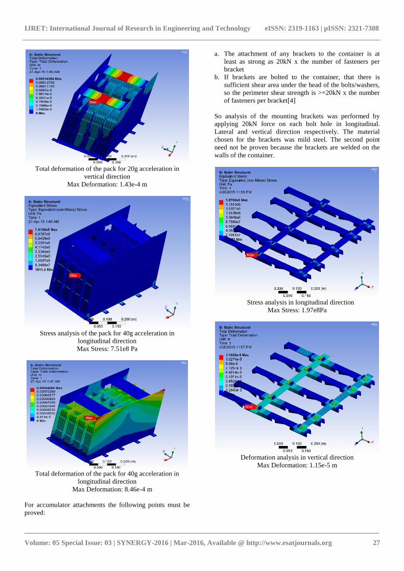
Total deformation of the pack for 20g acceleration in
vertical direction
Max Deformation: 1.43e-4 m
Stress analysis of the pack for 40g acceleration in
longitudinal direction
Max Stress: 7.51e8 Pa
Total deformation of the pack for 40g acceleration in
longitudinal direction
Max Deformation: 8.46e-4 m
For accumulator attachments the following points must be
proved:
a. The attachment of any brackets to the container is at
least as strong as 20kN x the number of fasteners per
bracket
b. If brackets are bolted to the container, that there is
sufficient shear area under the head of the bolts/washers,
so the perimeter shear strength is >=20kN x the number
of fasteners per bracket[4]
So analysis of the mounting brackets was performed by
applying 20kN force on each bolt hole in longitudinal.
Lateral and vertical direction respectively. The material
chosen for the brackets was mild steel. The second point
need not be proven because the brackets are welded on the
walls of the container.
Stress analysis in longitudinal direction
Max Stress: 1.97e8Pa
Deformation analysis in vertical direction
Max Deformation: 1.15e-5 m

IJRET: International Journal of Research in Engineering and Technology eISSN: 2319-1163 | pISSN: 2321-7308
_______________________________________________________________________________________
Volume: 05 Special Issue: 03 | SYNERGY-2016 | Mar-2016, Available @ http://www.esatjournals.org 28
Stress analysis in lateral direction
Max Stress: 2.43e8 Pa
Deformation analysis in lateral direction
Max Deformation: 2.432e-5 m
Stress analysis in lateral direction
FOS: 0.73
Deformation analysis in lateral direction
Max Deformation: 1.88e-5m
3. CONCLUSIONS
The battery pack was designed and manufactured with the
help of Optimum Lap, MATLAB, Solid Works and
ANSYS. The battery pack was designed according to the
powertrain and endurance requirements keeping in mind
feasibility in manufacturing and availability of resources.
ACKNOWLEDGEMENT
We would like to thank Team Ojas, VIT University Vellore
and Prof. Vijayakumar D their continuous help, support and
guidance throughout the project.
REFERENCES
[1]. Design and Analysis of a Battery for a Formula Electric
Car-Samuel Reineman
[2]. Module design and fault diagnosis in electric vehicle
batteries-Gregory. J. Offer*, Vladimir. Yufit, David. A.
HoweyI, Billy. Wu and Nigel. P. Brandon [3]. McGraw Hill-Handbook of Batteries
[4]. 2015-16 FSAE Rules
[5] Kokam-SLPB (Superior Lithium Polymer Battery)
Technical Specification [6] 95 Performance Graphs for AGNI MOTORS
BIOGRAPHIES
Ujjwal Ashish is doing his B. Tech in
Electrical and Electronics engineering from
VIT University, Vellore. He along with his
team represented India and VIT University
in Formula Student, Germany-2015. His
areas of interest are Power system Analysis
and Protection Switchgear.
Bishav Raj is doing his B.Tech in
Mechanical Engineering from VIT
University, Vellore. He along with his team
represented India and VIT University in
Formula Student, Germany-2015. His areas
of interests include Kinetics of Machinery,
Dynamics of Machinery and Strength of Materials.

IJRET: International Journal of Research in Engineering and Technology eISSN: 2319-1163 | pISSN: 2321-7308
_______________________________________________________________________________________
Volume: 05 Special Issue: 03 | SYNERGY-2016 | Mar-2016, Available @ http://www.esatjournals.org 29
Abhishek Kumar is doing his B. Tech in
Electrical and Electronics engineering from
VIT University, Vellore. His main areas of
interest are Automotive Electronics, Control
System.