Design and Fabrication of a Foldable Hexapod Robot Towards ...
6
Design and Fabrication of a Foldable Hexapod Robot Towards Experimental Swarm Applications Mahdi Agheli, Siamak G. Faal, Fuchen Chen, Huibin Gong, and Cagdas D. Onal Abstract— This paper presents the development of a lightweight origami-inspired foldable hexapod robot. Using a single sheet of polyester and a laser cutter, the hexapod robot can be fabricated and assembled in less than one hour from scratch. No screw or other external tools are required for as- sembly. The robot has built-in polyester fasteners considered in its crease pattern. The design uses four-bar mechanisms, which makes the robot flexible to be adjusted for different speeds or other task metrics. For a given desired locomotion velocity, various parameters of the four-bar mechanisms in the crease pattern can be modified accordingly. Design flexibility, ease of fabrication, and low cost make the robot suitable as an agent for swarm objectives. This work presents the foldable hexapod design and its kinematic analysis. The robot is fabricated, assembled, and tested for functionality. Experimental results show that the robot prototype runs with a maximum forward speed of 5 body lengths per second and turns in place with a speed of 1 revolution per second. The final robot weighs 42 grams. I. INTRODUCTION The collective behavior of a dense group of objects moving in large numbers is usually known as a swarm. Ants or bees are examples of swarm in nature. The development of a bio-inspired robotic swarm of ground robots is the main motivation of this work, where the overall task will be robust to operational failures of members. While agents can be relatively simpler in a multi-robot setting, they still need to satisfy low-level objectives such as locomotion and steering on unstructured or rough terrain. This paper addresses the design and fabrication of a mobile robot by folding a single sheet of plastic based on origami concepts, capable of maneuvering on rough terrain and suitable for rapid and inexpensive production towards experimental many-robot applications. Legged robots offer a salient solution for maneuvering on rough terrain. More specifically, the hexapod mechanism attracts attention due to its similarity to a variety of insects and ability to negotiate unstructured terrain with a high level of stability [1], [2], [3], [4], [5], [6]. In addition to maneuverability, high-speed, low-cost, and straightforward fabrication and operation of mobile robot agents plays a significant role for experimental many-robot systems of the future. Hexapod robots such as those presented in [7], [5], [6] that require considerable alignment and assembly operations of many distinct parts are not optimal for these Mahdi Agheli, Huibin Gong, and Cagdas D. Onal are with the Mechanical Engineering Department, Worcester Polytechnic Institute, MA 01609, USA {mmaghelih, hgong, cdonal}@wpi.edu Siamak G. Faal and Fuchen Chen are with the Robotic Engi- neering Program, Worcester Polytechnic Institute, MA 01609, USA {sghorbanifaal, fchen}@wpi.edu Fig. 1. Printed and folded hexapod mobile robot prototype. applications. Promising results that utilize minimal Degrees of Freedom (DOF) include DASH [8] and Kilobot [9]. DASH is a lightweight and fast hexapod robot that is suitable for locomotion on unstructured terrain. It utilizes the Smart Composite Microstructure (SCM) process for fabrication, which requires multi-layer alignment and a number of parts that need to be assembled. On the other hand Kilobot is a low-cost system developed for tabletop experimental multi- robot studies that and not suitable for real environments. Our objective in this research is to fill the gap between robots like Kilobot and DASH by making a robot with high maneuverability as well as easy and cost-effective fabrication process. Here, we propose a new design of a hexapod robot to satisfy these requirements while it is able to walk in rough environment. For this purpose, we take advantage of origami technique. It has been shown that origami, the traditional Japanese art of paper folding, is a reliable technique for fabricating robots by folding planar sheets. Felton et.al [10], [11] used origami for self-folding of shape memory composite, and Onal et.al showed an origami- inspired approach to make worm robots [12]. In this paper, we use the same origami technique to make our hexapod robot. Our robot is “printed” by laser machining a single polyester sheet [7] and then folded. Our printed and folded hexapod robot is shown in Fig. 1. The presented design in this paper does not use any external fasteners. All fasteners are embedded in the crease pattern, which reduces the assembly time. The robot is folded from a single sheet of plastic. The presented hexapod in this paper uses only two DC motors, the minimum number of actuators required for 2-D maneuverability with a differential drive controller. The electronic control circuitry is custom fabricated as part of
Transcript of Design and Fabrication of a Foldable Hexapod Robot Towards ...

Design and Fabrication of a Foldable Hexapod Robot TowardsExperimental Swarm Applications
Mahdi Agheli, Siamak G. Faal, Fuchen Chen, Huibin Gong, and Cagdas D. Onal
Abstract— This paper presents the development of alightweight origami-inspired foldable hexapod robot. Using asingle sheet of polyester and a laser cutter, the hexapod robotcan be fabricated and assembled in less than one hour fromscratch. No screw or other external tools are required for as-sembly. The robot has built-in polyester fasteners considered inits crease pattern. The design uses four-bar mechanisms, whichmakes the robot flexible to be adjusted for different speedsor other task metrics. For a given desired locomotion velocity,various parameters of the four-bar mechanisms in the creasepattern can be modified accordingly. Design flexibility, ease offabrication, and low cost make the robot suitable as an agentfor swarm objectives. This work presents the foldable hexapoddesign and its kinematic analysis. The robot is fabricated,assembled, and tested for functionality. Experimental resultsshow that the robot prototype runs with a maximum forwardspeed of 5 body lengths per second and turns in place witha speed of 1 revolution per second. The final robot weighs 42grams.
I. INTRODUCTIONThe collective behavior of a dense group of objects moving
in large numbers is usually known as a swarm. Ants orbees are examples of swarm in nature. The development ofa bio-inspired robotic swarm of ground robots is the mainmotivation of this work, where the overall task will be robustto operational failures of members. While agents can berelatively simpler in a multi-robot setting, they still need tosatisfy low-level objectives such as locomotion and steeringon unstructured or rough terrain. This paper addresses thedesign and fabrication of a mobile robot by folding asingle sheet of plastic based on origami concepts, capableof maneuvering on rough terrain and suitable for rapid andinexpensive production towards experimental many-robotapplications.
Legged robots offer a salient solution for maneuveringon rough terrain. More specifically, the hexapod mechanismattracts attention due to its similarity to a variety of insectsand ability to negotiate unstructured terrain with a highlevel of stability [1], [2], [3], [4], [5], [6]. In addition tomaneuverability, high-speed, low-cost, and straightforwardfabrication and operation of mobile robot agents plays asignificant role for experimental many-robot systems of thefuture. Hexapod robots such as those presented in [7],[5], [6] that require considerable alignment and assemblyoperations of many distinct parts are not optimal for these
Mahdi Agheli, Huibin Gong, and Cagdas D. Onal are with the MechanicalEngineering Department, Worcester Polytechnic Institute, MA 01609, USA{mmaghelih, hgong, cdonal}@wpi.edu
Siamak G. Faal and Fuchen Chen are with the Robotic Engi-neering Program, Worcester Polytechnic Institute, MA 01609, USA{sghorbanifaal, fchen}@wpi.edu
Fig. 1. Printed and folded hexapod mobile robot prototype.
applications. Promising results that utilize minimal Degreesof Freedom (DOF) include DASH [8] and Kilobot [9]. DASHis a lightweight and fast hexapod robot that is suitable forlocomotion on unstructured terrain. It utilizes the SmartComposite Microstructure (SCM) process for fabrication,which requires multi-layer alignment and a number of partsthat need to be assembled. On the other hand Kilobot is alow-cost system developed for tabletop experimental multi-robot studies that and not suitable for real environments.
Our objective in this research is to fill the gap betweenrobots like Kilobot and DASH by making a robot withhigh maneuverability as well as easy and cost-effectivefabrication process. Here, we propose a new design of ahexapod robot to satisfy these requirements while it is ableto walk in rough environment. For this purpose, we takeadvantage of origami technique. It has been shown thatorigami, the traditional Japanese art of paper folding, is areliable technique for fabricating robots by folding planarsheets. Felton et.al [10], [11] used origami for self-folding ofshape memory composite, and Onal et.al showed an origami-inspired approach to make worm robots [12].
In this paper, we use the same origami technique to makeour hexapod robot. Our robot is “printed” by laser machininga single polyester sheet [7] and then folded. Our printedand folded hexapod robot is shown in Fig. 1. The presenteddesign in this paper does not use any external fasteners. Allfasteners are embedded in the crease pattern, which reducesthe assembly time. The robot is folded from a single sheet ofplastic. The presented hexapod in this paper uses only twoDC motors, the minimum number of actuators required for2-D maneuverability with a differential drive controller. Theelectronic control circuitry is custom fabricated as part of

θ2
y
x
l5
l1
Rear Leg
l2
Middle Leg
l4
Front Leg
l3
l6
l7
θ1
θ7
θ4 θ3
θ6
1
2
3
4
Fig. 2. The generalized four-bar leg mechanism considered in the designof our foldable hexapod robot.
the robot manufacturing process and embedded on the robotbody, which reduces the cost compared to using commercialcircuits. The presented hexapod weighs 42 g and is designedto run based on the tripod gait as the fastest walking gait.
II. CONCEPTUAL DESIGN
In this section, the design considerations and requirementsof a hexapod robot for the proposed swarm application hasbeen explained. The discussion is followed by the detailsof the conceptual design, which satisfies the required designconstraints.
A. Design Considerations
Hexapod robots have been used commonly because oftheir innate balance and locomotion capability. To haveenough versatility and maneuverability over highly clutteredterrain, the robot needs to have at least 18 active DOF, threeper leg, in its joint space. Having 18 actuators dramaticallyincreases the cost, weight, and size of the robot. This makesan 18-DOF robot an inefficient agent for swarm applications.A possible solution is to reduce the cost of each robotby reducing the number of actuators. However, reducingthe number of active DOF of the robot will reduce itsmaneuverability and workspace. For our swarm objective, therobot needs to have capability to walk, turn, and maneuverover rough terrain. To satisfy this need, a minimum of twoactuators is required, one for each side of the robot body.This configuration will allow the hexapod robot to benefitfrom a differential drive locomotion system.
The other design requirement is to keep the weight of therobot as low as possible. While reducing the number of theactuators will reduce the weight of the robot, it is possibleto further reduce the weight by using a lightweight material.The material used should be invulnerable to collisions. Tosatisfy this need, the main body of the robot is formed by
Fig. 3. The proposed design of a 2-DOF hexapod mobile robot.
folding a polyester sheet. Since the manufacturing processincludes only laser cutting and folding the polyester, themanufacturing cost is minimal.
B. Proposed Design
The designed robot is conducted by a main body to whichtwo extended four-bar mechanisms are attached. The robot isconsidered to be longitudinally symmetric and it is designedto walk based on tripod gait.
Let’s define legs of the robot as follows: Front Left (FL),Middle Left (ML), Rear Left (RL), Front Right (FR), MiddleRight (MR), and Rear Right (RR). All three left legs (FL,ML, and RL) are part of the same mechanism which isachieved by extending a single four-bar as will be discussedlater. In the same way, all three right legs (FR, MR, andRR) are part of another four-bar mechanism with the samedesign as the left one. When the left four-bar mechanismworks, legs FL and RL have 180-degree phase differencewith the leg ML. On the other side of the robot, legs FRand RR have 180 degrees phase difference with the leg MR.All we need to do to have a tripod gait is to keep a 180-degree phase difference between the left and right four-barmechanisms. In this way legs FL, MR, and RL will be in thesame phase, and legs FR, ML, and RR will be in the samephase as well but with 180 degrees phase difference with theother legs. This enables the robot to walk using a tripod gait,which is the fastest locomotion gait possible for a hexapodmobile robot. The design and parameters are shown in Fig.2 and Fig. 3. As shown, Fig. 3 is a simplified version ofits general design depicted in Fig. 2. However, the presentedanalysis will retain its generality.
As shown in Fig. 2, the design starts with a simple four-bar mechanism 1-2-3-4 with the grounded link of 1-4. Thelink 3-4 is then extended to create the front leg and the link2-3 is extended to create the middle leg. For the rear leg,as we discussed, we need it to be in the same phase as thefront leg. Therefore, a parallelogram is created to achieve thisgoal. The exact same mechanism is designed for the other
side of the robot.
III. KINEMATIC ANALYSIS AND DESIGNOPTIMIZATION
Our final design for the four-bar based hexapod mobilerobot is developed as a result of an optimization process tomaximize the running speed of the robot.
A. Full Kinematic Analysis
As shown in Fig. 2, the kinematics of the mechanism usedfor each side of the robot is governed by the central crank-rocker mechanism as depicted in Fig. 3. The analysis of thisfour-bar mechanism is required for the robot’s locomotionanalysis and gait optimization.
We refer to ci and si as the cosine and sine of angle θi,respectively. Writing vector loops along x and y axes, yieldsthe position equations:
l2c2 + l3c3 − l4c4 − l1c1 = 0, (1)
l2s2 + l3s3 − l4s4 − l1s1 = 0. (2)
Solving (1) and (2) for θ3 and θ4 using the method introducedin [13] results in:
θ3 = atan2 (b, a)± atan2(√
a2 + b2 − c2, c), (3)
θ4 = atan2 (Ry + l3s3, Rx + l3c3) , (4)
where Rx, Ry , a, b, and c are defined as:
Rx = l2c2 − l1c1, (5)
Ry = l2s2 − l1s1, (6)
a = 2l3Rx, (7)
b = 2l3Ry, (8)
c = l42 −Rx
2 −Ry2 − l32. (9)
In the above equations, li represents the length of the linki illustrated in Fig. 2. As can be seen in (3), there are twosolutions for the value of θ3 for any value of θ2. These twosolutions correspond to the open and crossed configurationsof the mechanism. In our design, we have used the crossedconfiguration.
Velocity: To obtain the angular velocities, one can directlydifferentiate (1) and (2) as follows:
−l2θ̇2s2 − l3θ̇3s3 + l4θ̇4s4 = 0, (10)
l2θ̇2c2 + l3θ̇3c3 − l4θ̇4c4 = 0. (11)
Solving (10) and (11) for θ̇3 and θ̇4 yields:
θ̇3 = − l2θ̇2s24l3s34
, (12)
θ̇4 = − l2θ̇2s23l4s34
, (13)
where sij = sin (θi − θj).Using (3), (4), (12), and (13), it is possible to compute the
position and velocity of all the points on the mechanism.
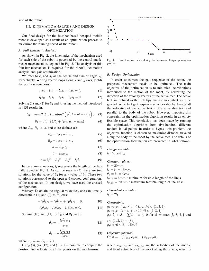
Fig. 4. Cost function values during the kinematic design optimizationprocess.
B. Design Optimization
In order to correct the gait sequence of the robot, theproposed mechanism needs to be optimized. The mainobjective of the optimization is to minimize the vibrationsintroduced to the motion of the robot, by correcting thedirection of the velocity vectors of the active feet. The activefeet are defined as the link tips that are in contact with theground. A perfect gait sequence is achievable by having allthe velocities of the active feet in the same direction andparallel to the body of the robot. However, imposing thisconstraint on the optimization algorithm results in an emptyfeasible space. This conclusion has been made by runningthe optimization algorithm from five-hundred differentrandom initial points. In order to bypass this problem, theobjective function is chosen to maximize distance traveledalong the body of the robot by the active feet. The details ofthe optimization formulation are presented in what follows.
Design variables:l1, l3, and l4
Constant values:l2 = 20mml6 = l7 = 15mmθ6 = θ7 = 0radlmin = 5mm : minimum feasible length of the linkslmax = 70mm : maximum feasible length of the links
Dependent variables:l5 = 2l1
Constraints:g1 to g3: lmin ≤ li ≤ lmax,∀i ∈ {1, 3, 4}g4 to g6: l2 − li + ε ≤ 0,∀i ∈ {1, 3, 4}g7: l2 + S −
∑i
li + ε ≤ 0 for S = max {l1, l3, l4} and
i ∈ {1, 3, 4} − {iS}g8: π/6 ≤ θ4 ≤ 5π/6
Objective function:Cost = −∫ vma.exdt− ∫ vfa.exdt,
where vma.ex and vfa.ex are the velocities of the middleand front active feet of the robot along the x axis, which is

Fig. 5. Foot trajectories of the hexapod robot as a result of the velocity-based kinematic design optimization.
Front and Rear Feet
Middle Foot
Fig. 6. Velocity patterns of the front, rear, and middle feet of the hexapodrobot as a result of kinematic design optimization.
parallel to the body of the robot. The constraints g1, g2, g3,and g8 deal with the feasibility of the design using the foldingtechnique which is discussed in Section IV. Constraints g4 tog6 are forcing l2 to remain as the crank of the mechanism.Finally, the constraint g7 deals with the Grashof condition.Since implementation of an optimization problem solver isbeyond the scope of this paper, available software packagesare used to solve this problem.
In this regard, two different optimization algorithms avail-able in MATLAB software are considered: the gradient basedand genetic algorithm based optimization methods. Sincethe system is highly nonlinear, it is obvious that the valuesobtained for the design variables might not be the globaloptimal solution of the system. To address this issue, theoptimization code is evaluated from different initial valuesand the solution that yields the minimum cost function ischosen as the final solution of the system. The minimizationof the cost function and the final cost value are depicted inFig. 4.
The trajectories of each foot of the robot are illustratedin Fig. 5. The velocities of the middle and front feet of therobot along the x-direction as functions of θ2 are illustratedin Fig. 6. Solid and dotted lines represent the status ofeach feet. While the velocity of the active foot is depictedwith solid lines, the velocity of the inactive foot is depictedwith dotted lines. In this figure, the blue curve illustrates
Fig. 7. The crease pattern of the foldable hexapod robot. Specific partof interest are marked. Black solid lines indicate cuts and red dashed linesindicate folds.
the velocity of the front and rear feet and the velocity ofthe middle foot is illustrated by green color. As discussedbefore, since there are no constraints on the direction of thevelocities, there are some instances that the active foot has avelocity in the opposite direction of the robots movement(i.e. negative velocities in the case of Fig. 6). Althoughthe lack of constraints on the velocities of each feet willintroduce vibrations on the movement of the robot, theoverall movement in a specific direction is guaranteed withthe chosen objective function. As depicted in Fig. 6, the totalintegral of the active feet is considerably larger than zerowhich will cause a net displacement in the forward direction.
IV. FABRICATION AND EXPERIMENTAL RESULTS
As shown in Fig. 7, our robot is made out of one singlesheet of plastic. The black lines in the crease pattern needto be cut and red dashed lines are folding lines.
At the beginning, a side view of the hexapod is drawnfor reference. From the picture shown, a rectangle piece ofplastic with triangular beam on every side is used as thebase of the robot, which provides rigidity and stability. Sixlegs of the robot are also triangular beams of 7 mm on eachside. Between two legs, we cut through only two sides ofthe triangle and the uncut side keeps them connected. Suchmechanism provides a one degree of freedom flexure jointand thus acts as the connector between legs. Then the linkagesystem we designed in the previous section can be realized.
We also develop a method to lock folded plastic togetherbecause the plastic tends to return to its original shape afterbeing folded. Such a self-locking mechanism is achievedby first adding a trapezoid-shape key and a hole on thecorresponding place where we want to fix the item on. Then,following the crease pattern on the key, we can fold it into arectangle which can go through the hole. After that, we thenunfold the key to prevent it from coming off. After manyexperiments, this method proves to be the most reliable andforce the folded plastic to stay in the desired shape.
The key and hole design not only allows us to avoid usingscrews and nuts, but also leads to another design principleto help us mount the motor and other potential discreteelectromechanical components on the robot using the plasticas a holder. Three rectangles are folded into a box while oneof the rectangles has a hole in the middle. The motor thenis inserted in the box while the crank goes through the hole.
This way, the motor is permanently mounted in its desiredposition and the main body wont rotate.
Laser machining the entire crease pattern takes approx-imately 5-6 minutes depending on the speed of the lasercutter. When finished, the crease pattern becomes its ownblueprint such that almost everyone can follow the creasepattern and fold the hexapod. On average, an experiencedresearcher can build the hexapod within an hour. Afterfolding several robots, we find that sometimes it is relativelydifficult to insert a small key in to the hole, so we try to adda small triangle on the shorter side of the trapezoid whichgreatly reduces the difficulty of locking.
The main controller of the robot uses ATMEL ATtiny2313microcontroller to control the applied voltage to the twoPermanent Magnet Brushed DC (PMBDC) motors that runthe cranks on the left and right side mechanisms. To do so,The Pulse Width Modulation (PWM) signals generated bymicrocontroller are fed into two H-bridges that are connectedto the terminals of the PMBDC motors. An Xbee moduleis used to send wireless commands to the robot usingasynchronous serial communication. With the use of a smalllithium polymer battery (3.7 V, 160 mAh, 4 g) as the mainpower source of the robot. The custom made Printed CircuitBoard (PCB) of the controller is etched using a simple solidink printer and an etching tank that contains Ferric Chloridesolvent. Although, for this prototype, the circuit is etchedfrom a separate plastic sheet laminated with copper, theetching technique provides a unique method of creating thecircuit on the same sheet that forms the body of the robot.
The overall robot manufacturing time from scratch isaround, but less than an hour. The fabricated robot has aground clearance of 15 mm. A rubber cover is used on thefeet to provide extra friction during motion. We tested ourfoldable hexapod robot prototype to validate its kinematicfunctionality. We ran the robot many times in differentdirections over various surfaces.
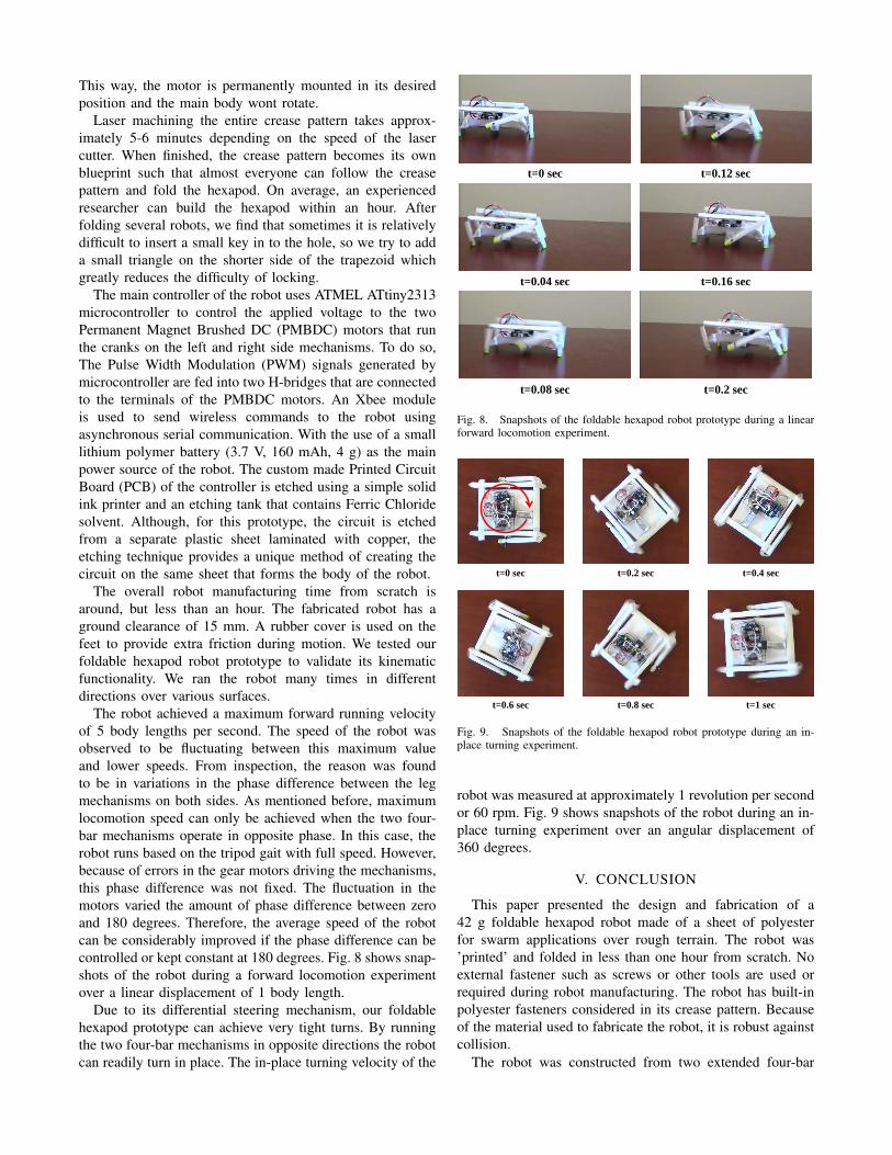
The robot achieved a maximum forward running velocityof 5 body lengths per second. The speed of the robot wasobserved to be fluctuating between this maximum valueand lower speeds. From inspection, the reason was foundto be in variations in the phase difference between the legmechanisms on both sides. As mentioned before, maximumlocomotion speed can only be achieved when the two four-bar mechanisms operate in opposite phase. In this case, therobot runs based on the tripod gait with full speed. However,because of errors in the gear motors driving the mechanisms,this phase difference was not fixed. The fluctuation in themotors varied the amount of phase difference between zeroand 180 degrees. Therefore, the average speed of the robotcan be considerably improved if the phase difference can becontrolled or kept constant at 180 degrees. Fig. 8 shows snap-shots of the robot during a forward locomotion experimentover a linear displacement of 1 body length.
Due to its differential steering mechanism, our foldablehexapod prototype can achieve very tight turns. By runningthe two four-bar mechanisms in opposite directions the robotcan readily turn in place. The in-place turning velocity of the
t=0 sec
t=0.2 sect=0.08 sec
t=0.16 sect=0.04 sec
t=0.12 sec
Fig. 8. Snapshots of the foldable hexapod robot prototype during a linearforward locomotion experiment.
t=0 sec
t=1 sect=0.8 sect=0.6 sec
t=0.4 sect=0.2 sec
Fig. 9. Snapshots of the foldable hexapod robot prototype during an in-place turning experiment.
robot was measured at approximately 1 revolution per secondor 60 rpm. Fig. 9 shows snapshots of the robot during an in-place turning experiment over an angular displacement of360 degrees.
V. CONCLUSION
This paper presented the design and fabrication of a42 g foldable hexapod robot made of a sheet of polyesterfor swarm applications over rough terrain. The robot was’printed’ and folded in less than one hour from scratch. Noexternal fastener such as screws or other tools are used orrequired during robot manufacturing. The robot has built-inpolyester fasteners considered in its crease pattern. Becauseof the material used to fabricate the robot, it is robust againstcollision.
The robot was constructed from two extended four-bar

mechanisms which are connected to the sides of the mainbody. The robot can be adjusted for different speeds simplyby controlling the speed of the motors. Two motors are usedto drive the four-bar mechanisms, one for each side. Thefour-bar mechanisms in the crease pattern can be modifiedto maneuver over different obstacles with different sizes.Design flexibility, ease of fabrication, and low price makethe robot suitable for swarm objectives. In this paper, Thekinematics of the robot was analyzed and the four-bar mech-anisms were optimized for maximum velocity. Experimentalresults showed that the foldable hexapod robot achieves aforward running speed of 5 body length per second and in-place turning speed of 1 revolution per second.
Future work includes overcoming the phase differencebetween two motors to keep the foldable hexapod robotoperate at the optimal speed with minimal variation. Also,a controller needs to be designed and utilized to get ac-curate motions of the robot in any desired direction. Afterthese initial steps, future work will focus on experimentalswarm algorithms for collaborative control of many foldablehexapod robots on unstructured terrain. Although we ran therobot many times in different directions over various surfacesincluding different flooring, the robot cannot traverse overhighly obstacles. The reason is that the ground clearance ofthe robot is only 15 mm. The next version of the robot willbe considered to have larger ground clearance to overcomethis shortage.
REFERENCES
[1] A. T. Baisch and R. J. Wood, “Design and fabrication of the harvardambulatory micro-robot,” in Robotics Research, pp. 715–730, Springer,2011.
[2] R. Sahai, S. Avadhanula, R. Groff, E. Steltz, R. Wood, and R. S.Fearing, “Towards a 3g crawling robot through the integration of mi-crorobot technologies,” in IEEE International Conference on Roboticsand Automation, pp. 296–302, 2006.
[3] A. M. Hoover, E. Steltz, and R. S. Fearing, “Roach: An autonomous2.4 g crawling hexapod robot,” in IEEE/RSJ International Conferenceon Intelligent Robots and Systems, pp. 26–33, 2008.
[4] A. T. Baisch, C. Heimlich, M. Karpelson, and R. J. Wood, “Hamr3:An autonomous 1.7 g ambulatory robot,” in IEEE/RSJ InternationalConference on Intelligent Robots and Systems, pp. 5073–5079, 2011.
[5] A. M. Hoover and R. S. Fearing, “Fast scale prototyping for foldedmillirobots,” in IEEE International Conference on Robotics and Au-tomation, pp. 886–892, 2008.
[6] A. T. Baisch, P. Sreetharan, and R. J. Wood, “Biologically-inspiredlocomotion of a 2g hexapod robot,” in IEEE/RSJ International Con-ference on Intelligent Robots and Systems, pp. 5360–5365, 2010.
[7] D. E. Soltero, B. J. Julian, C. D. Onal, and D. Rus, “A lightweightmodular 12-dof print-and-fold hexapod,” in IEEE/RSJ InternationalConference on Intelligent Robots and Systems, 2013.
[8] P. Birkmeyer, K. Peterson, and R. S. Fearing, “Dash: A dynamic 16ghexapedal robot,” in IEEE/RSJ International Conference on IntelligentRobots and Systems, pp. 2683–2689, 2009.
[9] M. Rubenstein, C. Ahler, and R. Nagpal, “Kilobot: A low costscalable robot system for collective behaviors,” in IEEE InternationalConference on Robotics and Automation, pp. 3293–3298, 2012.
[10] S. M. Felton, M. T. Tolley, B. Shin, C. D. Onal, E. D. Demaine,D. Rus, and R. Wood, “Self-folding with shape memory composites,”Soft Matter, pp. 7688–7694, 2013.
[11] S. M. Felton, M. T. Tolley, C. D. Onal, D. Rus, and R. J. Wood,“Robot self-assembly by folding: A printed inchworm robot,” in IEEEInternational Conference on Robotics and Automation, pp. 277–282,2013.
[12] C. D. Onal, R. J. Wood, and D. Rus, “An origami-inspired approachto worm robots,” IEEE Transactions on Mechatronics, pp. 430–438,2012.
[13] J. J. Craig, “Introduction to robotics: mechanics and control,” 2004,Prentice Hall.