DESIGN AND FABRICATE WELDING MACHINE CART …umpir.ump.edu.my/8552/1/CD7999_@_40.pdf · praktikal...
24
DESIGN AND FABRICATE WELDING MACHINE CART ZULFADLI ADHA BIN NADZRI Report submitted in partial fulfillment of the requirements for the award of the Diploma of Mechanical Engineering Faculty of Mechanical Engineering University Malaysia Pahang DECEMBER 2012
Transcript of DESIGN AND FABRICATE WELDING MACHINE CART …umpir.ump.edu.my/8552/1/CD7999_@_40.pdf · praktikal...

DESIGN AND FABRICATE WELDING MACHINE CART
ZULFADLI ADHA BIN NADZRI
Report submitted in partial fulfillment of the requirements for the award of the
Diploma of Mechanical Engineering
Faculty of Mechanical Engineering
University Malaysia Pahang
DECEMBER 2012

IV
ABSTRACT
Designing and fabricating a welding machine cart for the
welders is a product that fulfills the welder’s needs. This project uses
many materials such as mild steel, galvanized iron, stainless steel and
others. Overall, this project involves many processes, starting from the
design concept, fabrication and assembling procedures. Even though there
are many types of welding machine cart in the market, the completion of
this new model provides a more practical usage.

V
ABSTRAK
Mereka bentuk dan menghasilkan troli mesin kimpalan
untuk pengimpal merupakan salah satu produk untuk kepentingan
pengimpal. Projek ini menggunakan pelbagai jenis bahan seperti keluli
lembut, besi galvanic, keluli tahan karat dan sebagainya. Keseluruhan
projek ini melibatkan berbagai proses bemrula dengan idea konsep reka
bentuk, pemotongan bahan, mereka bentuk dan fabrikasi. Walaupun troli
mesin kimpalan seperti ini telah banyak di pasaran, namun kelaininan
dalam penghasilan troli ini telah dilakukan bagi memastikan ianya lebih
praktikal untuk digunakan.

VI
TABLE OF CONTENTS
TITLE PAGE
SUPERVISOR DECLARATION i
STUDENT DECLARATION ii
ACKOWLEDGEMENT iii
ABSTRACT iv
ABSTRAK v
TABLE OF CONTENT vi
LIST OF TABLES x
LIST OF FIGURES xi
LIST OF APPENDICES ix
CHAPTER 1 INTRODUCTION
1.1 Project synopsis 1
1.2 Project background 1
1.3 Problem statement 2
1.4 Objective of the project 2
1.5 Scope of the project 2
1.6 Project planning 2
1.7 Gantt chart 4
i
ii
iii
iv
v
v
i
x
xi
1
1
2
2
2
2
4

VII
1.8 Chapter conclusion 5
1.9 Thesis organization 5
CHAPTER 2 LITERATURE REVIEW
2.1 Terminology 8
2.2 Types of welding cart 9
2.2.1 Universal welding cart 1 9
2.2.2 Three tier welding cart 10
2.2.3 Universal welding cart 2 11
2.3 Chapter conclusion 12
CHAPTER 3 METHODOLOGY
3.1 Flow chart 14
3.2 Drawing/sketching and drawing selection 16
3.2.1 Concept 1 16
3.2.2 Concept 2 17
3.2.3 Concept 3 18
3.3 Concept evaluations 19
3.4 Chapter conclusion 20
5
5
8
9
9
10
11
12
14
16
16
17
18
19
20

VIII
CHAPTER 4 FABRICATION PROCESS
4.1 Material selection 21
4.2 Fabrication process and phase 23
4.2.1 Measuring process 23
4.2.2 Cutting process 24
4.2.3 Joining process 24
4.2.4 Finishing process 25
4.3 Finished product 26
4.4 Chapter conclusion 27
CHAPTER 5 RESULT AND DISCUSSION
5.1 The functioning of the welding cart 29
5.2 The problem encounters 30
5.3 Chapter conclusion 30
CHAPTER 6 CONCLUSION AND RECOMMENDATION
6.1 Conclusion 31
6.2 Recommendations 32
21
23
23
24
24
25
26
27
29
30
30
31
32

IX
REFERENCES 33
APPENDICES
A1 Design concept 1 34
A2 Design concept 2 35
A3 Design concept 3 36
B1 Finished design 37
B2 Finished product 1 38
B3 Finished product 2 39
B4 Finished product (with welding equipment) 40
33
34
35
36
37
38
39
40

X
LIST OF TABLES
TABLE NO TITLE PAGE
1.7 Gantt chart 5
3.1 Advantage & disadvantage of concept 1 17
3.2 Advantage &disadvantage of concept 2 18
3.3 Advantage & disadvantage of concept 3 19
3.4 Concept evaluations 20
4.1 List of materials 22
5
17
18
19
20
22

XI
LIST OF FIGURES
FIGURE NO TITLE PAGE
2.1 Universal welding cart 1 9
2.2 Three tier welding cart 10
2.3 Universal welding cart 2 11
3.1 Flow chart 14
3.1 Concept 1 16
3.2 Concept 2 17
3.3 Concept 3 18
4.1 Raw materials 23
4.2 Measuring process 23
4.2 Cutting process 24
4.2 Joining process (drilling) 25
4.2 Finishing process (brushing) 25
4.2 Finishing process (painting) 26
4.2 Finished product 27
5.1 The functioning of the welding cart 29

XII
LIST OF SYMBOLS
Mm millimeter
LIST OF ABBREVATIONS
UWC1 Universal Welding Cart 1
TTWC Three Tier Welding Cart
UWC2 Universal Welding Cart 2

1
CHAPTER 1
INTRODUCTION
For this chapter, it is about discussion of the project background,
problem statement, objective of the project, and lastly scope of the project.
1.1 PROJECT SYNOPSIS
In this project, the development of a welding machine cart so that
the welding machine can be moved from one place to another. The design
of the welding cart is more focus on placing the welding machine and the
gas cylinder plus providing mobility ability to the cart.
1.2 PROJECT BACKGROUND
This project is to understand the fundamental of designing and
fabricating a gas base welding machine cart for the use of welders in
welding process by adding a mobility capability to the machine.
The cart has three major compartments which are two for the
place of the welding machine and the other one is for gas tank
compartment. The cart will also has place for the wire to be hanged so that
it does not look muddled which will make things easier for the welders
during the process or moving it to another place.
The welding cart is to be able to support the weight of the welding
machine. This project is to design a perfectly match the size of the welding
machine and the gas tank. The design of this project is generate the
concept generation process continued with finalizing the design. After the
final design is decided then the fabrication is done as the material selection
is decided with the supervisor.

2
The idea of the project is based from problem statement and
focusing on the scope that is needed for the improvement of the cart.
1.3 PROBLEM STATEMENT
A Welder frequently found himself in hard position in the welding
process caused by the immobility of the welding machine and the
equipment for the welding process. The problem with the tools is that they
are not arranged in perfectly order and they often be found in many places
in the workshop which is messy plus causing a delay in the fabrication
process.
1.4 OBJECTIVE OF THE PROJECT
To developed and fabricate a welding equipment cart for mobility
of the welding equipment and safety gear and also additional tool required
during a welding process.
1.5 THE SCOPE OF THE PROJECT
The welding cart is more focused on Gas base welding machine
with a gas tank as one of its component and its equipment which are many
and not in appropriate order in the workshop or workplace.
1.6 PROJECT PLANNING
The first thing to in this project, a meeting with supervisor in the
first week is done to fare the schedule of weekly meetings. The purpose is
to update the supervisor on the progress of the project and guided by the
supervisor to solve difficulty.
Briefing based on the introduction and next task of the project is
given by supervisor. Make research of literature review with the means of

3
the internet, books, available published articles and materials that is
related to the title.
The designing phase starts by sketching three models of the
welding cart using manual sketch on A4 papers. Do the comparison
between three and come out with the best concept design. The fourth
design is drawn in software applications which helps to draw a better
dimension downloaded from internet which is Software Solid Work.
Next is the preparation of mid-presentation of the project. Before
presenting, the supervisor will see through the slide presentations and
comment on corrections to be made. Then, presentation on the knowledge
attained and instilled in the design phase is presented to a panel of three
judges.
Following up, is the fabrication of make some method for this
project. The material is decided plus with a list of the material and
dimension. The planning of fabrication process for the project is done.
After that, the fabrication process is proceed. It would take seven
weeks to get this design and fabrication process alteration done. A few
analysis and testing of the welding cart are done plus the correction of the
error. Finish the fabrication process with painting process.
After that, the final report writing and final presentation will be
the last task to be accomplished. The supervisor will review the final
presentation and revise mistakes to be amended. The final presentation
then again will be presented to three panels. A draft report would then be
submitted to the supervisor to be point out the flaws. Corrections are done
and the real final report is handed over as a completion of the final year
project.
1.7 GANTT CHART

4
Based from the Gantt chart on table 1.7, the project starts
with the title distribution and briefing with the supervisor which actually
happened in week two due to some technical issues with the place timing
of the meeting.
Week 2, proceed with the literature review for information
collecting followed by methodology in week 3. Then concept generation,
deciding the final concept, initial presentation and final presentation that
succeedly met on respective week.
The fabrication process finished three weeks late than
planned due to not enough tool and material causing the functioning test to
be done two weeks late. Then project is continued with the report writing
after the project is proved functioning. Finally the final presentation to
show the complete work done for this project.

5
1.8 CHAPTER CONCLUSION.
Every project needs objectives; scope, problem statement
and also planning so that the project can be proceed successfully.
Therefore, these criteria are successfully determined and the next step of
the project can be proceed.
1.9 THESIS ORGANIZATION.
Chapter 1 provides the necessary intro to start a project. A
project needs to have its own simple synopsis to provide a clear
introduction to the project. The back ground of the project also covered as
WEEK TASK
1 2 3 4 5 6 7 8 9 10 11 12 13 14
Title/Briefing by
Supervisor
Planning actual
Literature
Review
Planning actual
Methodology Planning actual
Concept
generation
Planning actual
Final
Concept
Planning actual
Initial
presentation
Planning actual
Material
Selection
Planning actual
Fabrication Planning actual
Functioning Test Planning actual
Report Project Planning actual
Final
Presentation
Planning actual
Table 1.7: Gantt chart

6
it plays an important role knowing the more about the project. This
chapter also provides the necessary objective as to set it as the target on
what this project will consume to. A problem statement also mentioned as
it will determine that this project is developed to solve problems that
commonly occur to the target people. Scopes are given to make it more
specific. Finally the planning of the project, a project is needed to be
planned so that it can be done accordingly as following the planned. A
Gantt chart to planned the duration of the project so that the time limit of
the project can be set.
Chapter 2 is about collecting information to be used for the
project. The information is collected by many references such as internet,
magazines, new paper and many other source of information. This chapter
mostly based on the easiest source of information which is the internet.
The information regarding this project is collected from either previous
project or the product available on the market as this project is based on
the products that are available in the market. Then the information is then
be view as to generate new ideas for the production a new product which
can be practically used based on the market.
Chapter 3 is about producing new ideas for the fabrication
of a new product so that it can be used. Flow chart is constructed to get a
clear view on the flow of this project. Three ideas are to be generated and
the ideas generated mostly based on the information that has been
collected during the chapter 2. Then, evaluation is made to determine
between the three ideas to choose the best design for the fabrication.
Several traits or characteristic is made up and the by evaluating between
the three design, the ideas which meets all the traits is considered as the
most ideal design for the fabrication.

7
Chapter 4 provides the information on the fabrication
process which has been used for producing the new product which the
design is decided during the chapter 3. This chapter will show the phase of
the fabrications and the processes that will be going through to produce
the product. This chapter also tells about the material selection where the
dimension is shown to list down the types of materials that has been used
for the project. Finally, this chapter will show the finished product as to
state that the fabrication process is finished.
Chapter 5 tells about the discussion made up to view the
problems occur during the production of this project. The problem
encounter will act as the reference for the next project. This chapter also
provides the discussion about the functioning of the product that has been
produce to get how the product works and prove that the product is
functioning.
Chapter 6 is about the conclusion that can be made through
out this entire project. The conclusion covers on what have been learn
through this product or project. Recommendation also provided so that
any new idea will have the reference thus problems can be avoided.

8
CHAPTER 2
LITERATURE REVIEW
The title development of welding machine cart requires an
amount of good understanding on the knowledge of the science.
Therefore, executing a research is necessary to obtain all the information
available and related to the topic. The information or literature reviews
obtained are essentially valuable to assist in the construction and
specification of this final year project. With this grounds established, the
project can proceed with guidance and assertiveness in achieving the
target mark.
2.1 TERMINOLOGY
Welding is a materials joining process meaning two or more
parts are coalesced at their contacting surfaces by suitable application of
heat and or pressure. Welding provide permanent joint and the joint
strength is typically as high as strength as base metals.
The major disadvantage of welding is that it usually performed
manually so the cost for labor is high. Welding machine comes with a big
size which makes it impossible to do the welding with bringing the work
piece closer to the welding machine to do the welding process. The
implication is the immobility of the welding machine will slow down the
welding process.
Therefore, to overcome this disadvantage, welding machine cart
is created so that the laboring will become easier and reduced. This is
because the welding cart will make things easier for the welders to do the
9
welding even though it involves various place and distance as the welding
machine is equipped with mobility ability.
2.2 TYPES OF WELDING MACHINE CART.
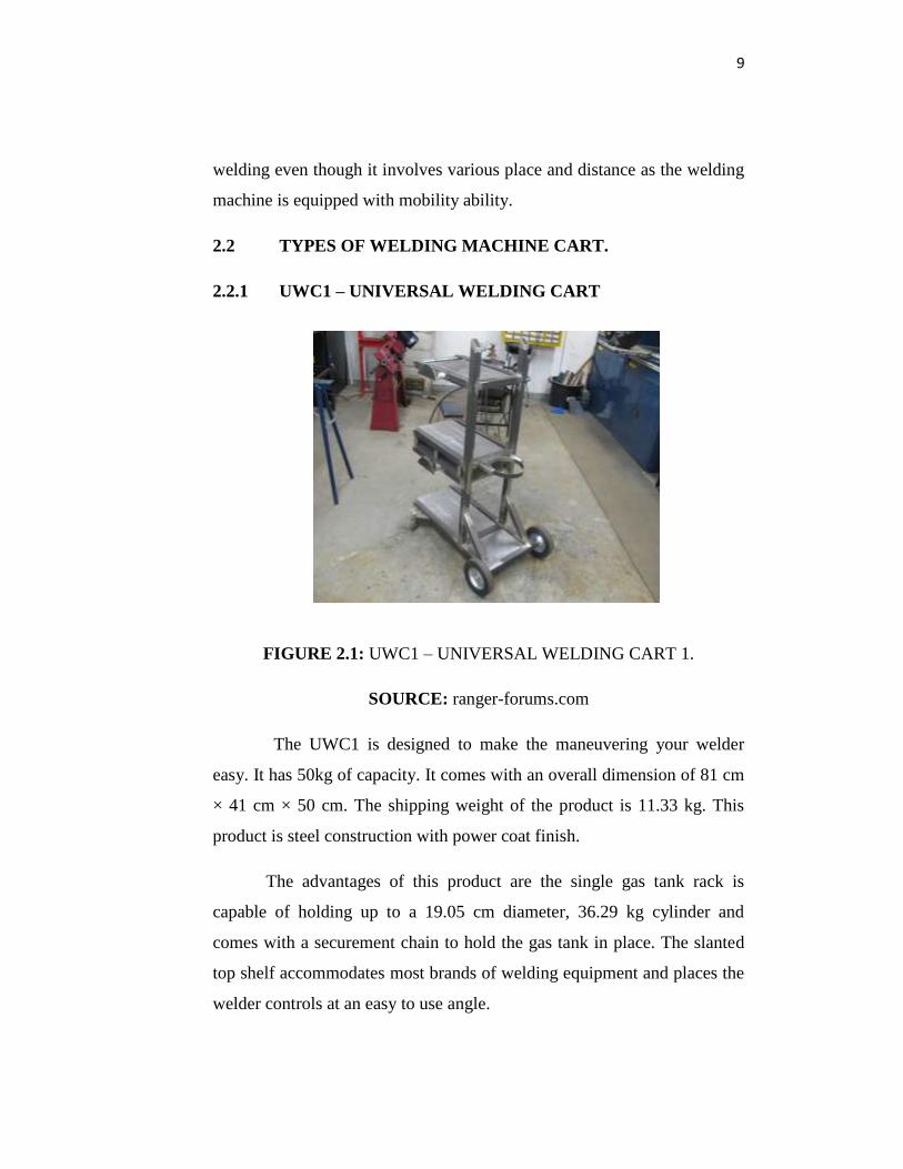
2.2.1 UWC1 – UNIVERSAL WELDING CART
FIGURE 2.1: UWC1 – UNIVERSAL WELDING CART 1.
SOURCE: ranger-forums.com
The UWC1 is designed to make the maneuvering your welder
easy. It has 50kg of capacity. It comes with an overall dimension of 81 cm
× 41 cm × 50 cm. The shipping weight of the product is 11.33 kg. This
product is steel construction with power coat finish.
The advantages of this product are the single gas tank rack is
capable of holding up to a 19.05 cm diameter, 36.29 kg cylinder and
comes with a securement chain to hold the gas tank in place. The slanted
top shelf accommodates most brands of welding equipment and places the
welder controls at an easy to use angle.

10
The disadvantage of this product is that it can only hold a small gas
tank causing a limited time of used the welding machine. This also can
cost a lot of money for changing the gas tank. These carts also do not have
a handle causing a slight of difficulty for maneuvering to a big distance.
2.2.2 TTWC – THREE – TIER WELDING CART
FIGURE 2.2: TTWC – THREE – TIER WELDING CART
SOURCE: hobartwelders.com
The Three – tier welding cart comes with 50 kg capacity with an
overall dimension of 69.85 cm × 41.18 cm × 73.025 cm. It has a shipping
weight of 14.06 kg. These welding machines cart also a steel construction
with power coat finish.
The advantages of this welding machine cart are welders control is
put at a comfortable working height and has storage shelves for all your
tools and accessories. The gas tank rack is capable of holding up to a
16.51cm diameter cylinder and comes with two securement chains to hold
the cylinder in place. The slanted top shelf accommodates most brands of
welding equipment and places the welder controls at an easy to use angle.

11
The disadvantages of this welding machine cart are it does not
have handle for the welder to hold and make it easier for the maneuvering
of the welding cart. This condition can put the welder a dangerous
situation where the welding machine might fall during the maneuvering of
the cart.
2.2.3 UWC2 – UNIVERSAL WELDING CART 2.
FIGURE 2.3: UWC2 – UNIVERSAL WELDING CART 2
SOURCE: weldingweb.com
The UWC2 is a welding machine cart for welding process that
comes with 50kg capacity and an overall dimension of 82.04 cm × 46.48
cm × 75.44 cm. This welding machine cart also has a shipping weight of
14.51kg plus it is a steel construction with coat finish.
The advantages of the welding machine cart are the single cylinder
gas tank rack is capable of holding up to a 19.05 cm diameter, 36.29 kg
cylinder and comes with a securement chain to hold the cylinder gas tank
in place. The slanted top shelf accommodates most brands of welding
equipment and places the welder control at an easy to use angle. This cart
comes with a new fold handle. The used of the handle is to easily move

12
your welding equipment in to place the fold down the handle for the easy
access to welder controls. The wrap around cable holders help keep your
cables organized.
The disadvantage of this welding machine cart is that only small
size cylinder can be place on the cart even though the amount is two. The
cart is not stable and might fall it is moved.
2.3 CHAPTER CONCLUSION.
The conclusion for this chapter is that all the information
plans for continuing this project has been collected and it is found that the
information that has been collected play an important role and will highly
contribute to the process in the chapter two which will be the phase of
producing a different product from the current one thus the will project
will running smoothly.
13
CHAPTER 3
METHODOLOGY
In designing and fabricating the welding machine cart, a flow of
methods was needed to be used for the designing. First of all, a process
planning had to be charted out. This will act as a guideline to be followed
accordingly so that, the final model sees the requirement and time could
be fared. This would determine the efficiency of the project to be done.
Regulating and analyzing these steps are very important as each of the
steps has its own criteria to be followed.

14
3.1 FLOW CHART
FIGURE 3.1: PROJECT FLOW CHART
Start
Title selection
Data collection
Literature review
Design & sketching
Concept
selection
NO
YES
Functioning
test
End
Final
Presentation
Report
Fabrication
Material selection
NO
YES
Initial
Presentation
Final concept