DESIGN AND DYNAMIC ANALYSIS OF 120 Ton ... the durability of the EOT crane Structure by finite...
8
International Research Journal of Engineering and Technology (IRJET) e-ISSN: 2395-0056 Volume: 05 Issue: 02 | Feb-2018 www.irjet.net p-ISSN: 2395-0072 © 2018, IRJET | Impact Factor value: 6.171 | ISO 9001:2008 Certified Journal | Page 1055 DESIGN AND DYNAMIC ANALYSIS OF 120 Ton CAPACITY EOT CRANE GIRDER 1 N.PAVAN KUMAR PATNAIK, 2 Dr. V. NAGA BHUSHANA RAO 1 M.tech Student, Department of Mechanical Engineering, Raghu Institute of Technology, Visakhapatnam 2 Professor, Department of Mechanical Engineering, Raghu Institute of Technology, Visakhapatnam -----------------------------------------------------------------------------***------------------------------------------------------------------------------- Abstract-Electric Overhead Travelling (EOT) Crane is one of the essential industrial equipment for material handling. Generally structural component are subjected to complex loadings in their working life and cost of the material handling equipment is depend on the weight of the material. The weight reduction has been increased that motivate me to work on optimal design of heavy electric overhead travelling crane bridges. Girder travelling crane is flexible and evident for almost any application the main component of overhead crane is girder beam that transfers load to structural member. Generally more stresses are produced at centre of girder on continuous process of loading and unloading. Due to this cyclic process of loading and unloading, the girder becomes weak and yields cracking at the centre of it. So one of the ways for reducing the failure is to reduce the concentration of stresses to improve of life of girder. The main objective of our project is to reduce the cost of girder and to optimize the performance of girder with respect to strength. Using the basic fundamentals, to do analysis of 5 m long, 120 tons capacity girder. A prototype is organized to perform the experiments. Buckling is one of the important parameter which needs to be considered separately as it may cause the complete structure to fail. Utilization of modern design optimization tools will help us to get the optimum solution. Design optimization is performed using detailed 3D finite element method of analysis by changing the geometry parameters to control any possible buckling, light weight and for safe stress and deflection. A simple procedure has been introduced to optimize various parameters of the welded box section of bridge and then comparing the analysis results with the analytically results. Keywords: EOT (Electric overhead travelling), Grider, Static Analysis, Modal Analysis, Harmonic Analysis, Vibrations, Buckling Analysis. 1. Introduction A crane is a machine that is capable of raising and lowering heavy objects and moving the objects from one place to other. Generally overhead crane composed of lifting trolley, crane moving system and metal structure. The design of overhead cranes vary widely according to their major operational specifications such as: type of motion of the crane structure, weight and type of the load, location of the crane, geometric features, operating regimes and environmental conditions. Selecting the right type of overhead crane is critical to streamline workflow and to maximize the productivity. The main component of the overhead crane is girder beam which transfers load to its structural member. 2. Literature review N. Raghu Prasad, Jeeoot Singh [1], in his paper investigates into the Buckling of the plates. Modal analysis using Finite Element Method (FEM) is used to determine natural frequencies and mode shapes. These plates are simply supported ends. Various methods of meshing were used to get optimized results. Indian Standard (807-2006) [2], in this standard describe design of structural portion for cranes, hoists, specifies permissible stress and other details of the design. In order to ensure economy in design in reliability in operation .To deal with the subject conventionally, cranes have been broadly classified into eight categories based on their nature of duty and number of hours in service per year. It is procedure or manufactures responsibility to ensure the correct classification. K.Naresh Chauhan ,P.M.Bhatt [3], in his paper, Improving the durability of the EOT crane Structure by finite element analysis and optimize the Girder material for improving its solidity states that crane is one of the most important material handling equipment and wide application in different fields of engineering. Many cranes are used beyond their lifting capacity so analysis of crane structure is essential .So the analysis has been calculated. Abhinay Suratkar and Vishal Shukal [4], in his paper Three Dimensional Modeling and finite element analysis of EOT Crane, made a comparison between the analytical calculations and FE analysis .As a result study they have proposed the design optimization method for Over head crane. Redenko N [5], in the book of material handling equipment briefed the structure of overhead travelling crane .The structure of an overhead travelling crane with a plate girder is composed of two main longitudinal girders
Transcript of DESIGN AND DYNAMIC ANALYSIS OF 120 Ton ... the durability of the EOT crane Structure by finite...

International Research Journal of Engineering and Technology (IRJET) e-ISSN: 2395-0056
Volume: 05 Issue: 02 | Feb-2018 www.irjet.net p-ISSN: 2395-0072
© 2018, IRJET | Impact Factor value: 6.171 | ISO 9001:2008 Certified Journal | Page 1055
DESIGN AND DYNAMIC ANALYSIS OF 120 Ton CAPACITY EOT CRANE GIRDER
1N.PAVAN KUMAR PATNAIK, 2Dr. V. NAGA BHUSHANA RAO
1M.tech Student, Department of Mechanical Engineering, Raghu Institute of Technology, Visakhapatnam 2Professor, Department of Mechanical Engineering, Raghu Institute of Technology, Visakhapatnam
-----------------------------------------------------------------------------***-------------------------------------------------------------------------------
Abstract-Electric Overhead Travelling (EOT) Crane is one of the essential industrial equipment for material handling. Generally structural component are subjected to complex loadings in their working life and cost of the material handling equipment is depend on the weight of the material. The weight reduction has been increased that motivate me to work on optimal design of heavy electric overhead travelling crane bridges. Girder travelling crane is flexible and evident for almost any application the main component of overhead crane is girder beam that transfers load to structural member. Generally more stresses are produced at centre of girder on continuous process of loading and unloading. Due to this cyclic process of loading and unloading, the girder becomes weak and yields cracking at the centre of it. So one of the ways for reducing the failure is to reduce the concentration of stresses to improve of life of girder. The main objective of our project is to reduce the cost of girder and to optimize the performance of girder with respect to strength. Using the basic fundamentals, to do analysis of 5 m long, 120 tons capacity girder. A prototype is organized to perform the experiments. Buckling is one of the important parameter which needs to be considered separately as it may cause the complete structure to fail. Utilization of modern design optimization tools will help us to get the optimum solution. Design optimization is performed using detailed 3D finite element method of analysis by changing the geometry parameters to control any possible buckling, light weight and for safe stress and deflection. A simple procedure has been introduced to optimize various parameters of the welded box section of bridge and then comparing the analysis results with the analytically results.
Keywords: EOT (Electric overhead travelling), Grider, Static Analysis, Modal Analysis, Harmonic Analysis, Vibrations, Buckling Analysis.
1. Introduction
A crane is a machine that is capable of raising and lowering heavy objects and moving the objects from one place to other. Generally overhead crane composed of lifting trolley, crane moving system and metal structure. The design of overhead cranes vary widely according to their major operational specifications such as: type of motion of the crane structure, weight and type of the load, location of
the crane, geometric features, operating regimes and environmental conditions. Selecting the right type of overhead crane is critical to streamline workflow and to maximize the productivity. The main component of the overhead crane is girder beam which transfers load to its structural member.
2. Literature review N. Raghu Prasad, Jeeoot Singh [1], in his paper investigates into the Buckling of the plates. Modal analysis using Finite Element Method (FEM) is used to determine natural frequencies and mode shapes. These plates are simply supported ends. Various methods of meshing were used to get optimized results. Indian Standard (807-2006) [2], in this standard describe design of structural portion for cranes, hoists, specifies permissible stress and other details of the design. In order to ensure economy in design in reliability in operation .To deal with the subject conventionally, cranes have been broadly classified into eight categories based on their nature of duty and number of hours in service per year. It is procedure or manufactures responsibility to ensure the correct classification. K.Naresh Chauhan ,P.M.Bhatt [3], in his paper, Improving the durability of the EOT crane Structure by finite element analysis and optimize the Girder material for improving its solidity states that crane is one of the most important material handling equipment and wide application in different fields of engineering. Many cranes are used beyond their lifting capacity so analysis of crane structure is essential .So the analysis has been calculated. Abhinay Suratkar and Vishal Shukal [4], in his paper Three Dimensional Modeling and finite element analysis of EOT Crane, made a comparison between the analytical calculations and FE analysis .As a result study they have proposed the design optimization method for Over head crane. Redenko N [5], in the book of material handling equipment briefed the structure of overhead travelling crane .The structure of an overhead travelling crane with a plate girder is composed of two main longitudinal girders

International Research Journal of Engineering and Technology (IRJET) e-ISSN: 2395-0056
Volume: 05 Issue: 02 | Feb-2018 www.irjet.net p-ISSN: 2395-0072
© 2018, IRJET | Impact Factor value: 6.171 | ISO 9001:2008 Certified Journal | Page 1056
assembled with end carriages which accommodate the travelling wheel. The main factor in the solution of plate girders are safe unit bending stress and permissible girder deflection. The vertical loads on the girders are weights and the force exerted by the wheel of the trolley carrying the maximum load.
3. Design of EOT Crane: Capacity 120T and span of the crane is 5m class II crane as per IS classification. 1. Type of crane = Double Girder type
2. Capacity = 120 Ton
3. Span = 5 Meters
4. Trolley weight = 4.7 Tons
5. Class of Duty = II-IS2062
6. Impact factor = 0.25
7. Panel dimension = 550 mm Height x 512 mm width x 19 mm Thick
8. Type of material= Structural steel (IS 2062 E250)
3.1 Material Properties Four different materials were used for the analysis of the EOT Crane to know the best material for the chassis. The properties of the materials are shown below.
Table 1: Material Properties
3.2 Modelling of EOT Crane Girder: Pro-E is now recreated as CREO which is software, is used to model the EOT Crane Girder. EOT Crane is designed in CREO software.
Fig 1: Created 3D Model of Crane Girder in CREO.
To find out the better design model for the Crane girder, different types of materials were used to design new models and simulate them in ANSYS. The best design was obtained based on the static analysis on the different models at different materials. Double girder is main element to carrying the load and total load acting on girder of EOT.
Fig 2: Assembly of girder These models are used for static analysis using the materials Structural Steel, FE410, Carbon steel, mild steel-2062. The best model is selected based on results and that model is used for further analysis.
3.3 Theoretical Calculation: For the material Structural Steel:
Live Load:
Bending Moment (B.M) =
Where W= Load applied on Square Girder
L= Span of EOT Crane Girder
Bending Moment (B.M) =
= 750000 N-m
Moment of inertia (I)= (a4-b4)/12
b= width of the girder = 512 mm
a= height of the girder = 550 mm
w= thickness of the girder = 19 mm
I = 1.89 x 10 -3 mm4
Deflection
=
= 0.00413 m = 4.13 mm Steel Double girder own weight is main impact factor to find out deformation and bending moment. Here total
MATERIAL Carbon steel
FE 410 MS-2062 Structural Steel
young modulus
G.Pa 207 200 210 200
Poisson ratio
0.3 0.3 0.29 0.3
density kg/m3 7860 7800 7850 7800

International Research Journal of Engineering and Technology (IRJET) e-ISSN: 2395-0056
Volume: 05 Issue: 02 | Feb-2018 www.irjet.net p-ISSN: 2395-0072
© 2018, IRJET | Impact Factor value: 6.171 | ISO 9001:2008 Certified Journal | Page 1057
mass of girder is calculated according to unit mass of girder and volume of steel. Here 4700 kg value is found.
Self Weight:
Mass of double girder = 4700 kg
WL = 47000 N
Bending Moment (B.M) =
=
= 29375 N-m
Deflection =
=
= 2.02 x
= 0.202 mm
Impact Load: Here impact load is considered according to plant standards. Here 0.25 of live load is considered in the design. 0.25 X Live Load = 0.25 x 750000 = 18750 N-m
Bending Moment (B.M) = 18750 N-m
Deflection
=
Deflection = 8.82 X mm. From the three types of loading results, the combination loading results are calculated as below.
Total Bending Moment (B.M): = Live Load + Impact Load + Self Weight
= 750000 + 18750 + 29375
= 798125 N-m
Total Deflection = 4.13 + 8.82 X + 0.20
= 4.33 mm Similarly Theoretical calculations was performed on Crane Girder using other three materials FE-410, Mild steel and Carbon steel and the results are studied.
5. The Finite Element Analysis (FEA) ANSYS 18.0 is used to run the analysis. The previously created IGS file is imported on ANSYS file geometry. Solid mesh is used to divide the geometric body in to small strips (Finite elements). Fixed boundary conditions are applied at the supports of frame. The Load applied on the exterior top of the chassis is 60000N.
Fig 3: Meshed Finite element model of girder assembly
5.1. Boundary Conditions and Loading While doing software based analysis there is need to apply boundary conditions. Fixed boundary conditions are applied at the suspension supports of the frame. The Load is applied on the exterior top of the Crane Girder.
Fig 4: Boundary Conditions and loading conditions.
5.2 Static Analysis Static analysis is used to determine the stress and deformation when the Crane Girder structure receives the loads. The above mentions models with four different material Structure steel, FE-410, Carbon steel, mild steel 2062were analysed and result are studied. The deformation of the original Crane Girder assembly is show below.

International Research Journal of Engineering and Technology (IRJET) e-ISSN: 2395-0056
Volume: 05 Issue: 02 | Feb-2018 www.irjet.net p-ISSN: 2395-0072
© 2018, IRJET | Impact Factor value: 6.171 | ISO 9001:2008 Certified Journal | Page 1058
Fig 5: Total deformation of girder assembly at 300000N loading (Original model)
Maximum deformation occurs at the hook portion. Because there is no support at the nose, so there is a major chance of the hook to get bent .Minimum deformation appears at the supports of the girder all together maximum deformation is 4.412 mm. This deformation is considerable.
Fig 6: Von-misses stresses of girder assembly at 300000 N loading (Original model).
There are more stresses occurring at the middle of girder and in hook component. There by compressive stresses occurred. The entire body is crosses the design limit. But maximum stresses are present mainly at sharp corners of the girder and between the connection of girder and support. Is 92.65 mpa.
Fig 7: Total deformation of girder assembly at 300000N loading (Carbon steel)
Maximum deformation occurs at the hook portion. Because there is no support at the nose, so there is a major chance
of the hook to get bent .Minimum deformation appears at the supports of the girder all together maximum deformation is 4.610 mm.
Fig8: Von-misses stresses of girder assembly at 300000 N loading (Carbon Steel)
There are more stresses occurring at the middle of girder and in hook component. There by compressive stresses occurred. The entire body is crosses the design limit. But maximum stresses are present mainly at sharp corners of the girder and between the connection of girder and support. Is 93.79 mpa.
Fig9: Total deformation of girder assembly at 300000N loading (FE410)
Maximum deformation occurs at the hook portion. Because there is no support at the nose, so there is a major chance of the hook to get bent .Minimum deformation appears at the supports of the girder all together maximum deformation is 4.47 mm.
Fig 10: Von-misses stresses of girder assembly at 300000 N loading (FE 410)
International Research Journal of Engineering and Technology (IRJET) e-ISSN: 2395-0056
Volume: 05 Issue: 02 | Feb-2018 www.irjet.net p-ISSN: 2395-0072
© 2018, IRJET | Impact Factor value: 6.171 | ISO 9001:2008 Certified Journal | Page 1059
There are more stresses occurring at the middle of girder and in hook component. There by compressive stresses occurred. The entire body is crosses the design limit. But maximum stresses are present mainly at sharp corners of the girder and between the connection of girder and support. Is 92.69 mpa.
Fig11: Total deformation of girder assembly at 300000N loading (MILD STEEL)
Maximum deformation occurs at the hook portion. Because there is no support at the nose, so there is a major chance of the hook to get bent .Minimum deformation appears at the supports of the girder all together maximum deformation is 4.41 mm.
Fig12: Von-misses stresses of girder assembly at 300000 N loading (MILD STEEL)
There are more stresses occurring at the middle of girder and in hook component. There by compressive stresses occurred. The entire body is crosses the design limit. But maximum stresses are present mainly at sharp corners of the girder and between the connection of girder and support. Is 92.658 mpa
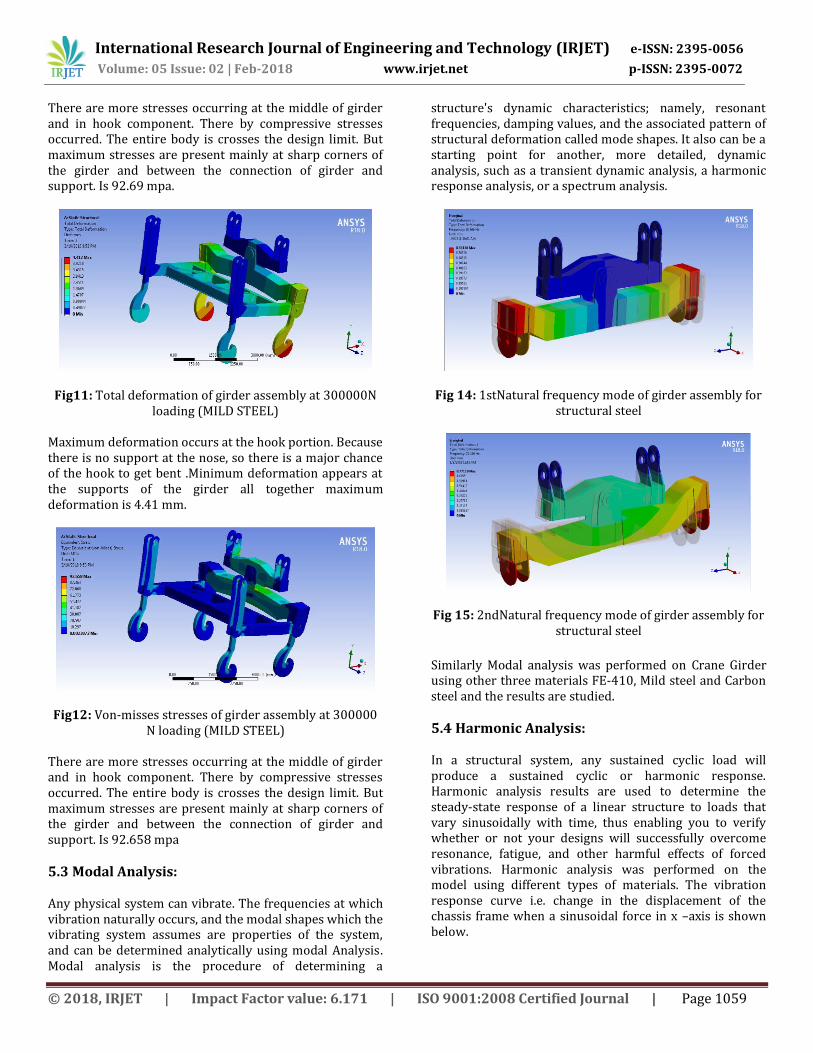
5.3 Modal Analysis: Any physical system can vibrate. The frequencies at which vibration naturally occurs, and the modal shapes which the vibrating system assumes are properties of the system, and can be determined analytically using modal Analysis. Modal analysis is the procedure of determining a
structure's dynamic characteristics; namely, resonant frequencies, damping values, and the associated pattern of structural deformation called mode shapes. It also can be a starting point for another, more detailed, dynamic analysis, such as a transient dynamic analysis, a harmonic response analysis, or a spectrum analysis.
Fig 14: 1stNatural frequency mode of girder assembly for structural steel
Fig 15: 2ndNatural frequency mode of girder assembly for structural steel
Similarly Modal analysis was performed on Crane Girder using other three materials FE-410, Mild steel and Carbon steel and the results are studied.
5.4 Harmonic Analysis: In a structural system, any sustained cyclic load will produce a sustained cyclic or harmonic response. Harmonic analysis results are used to determine the steady-state response of a linear structure to loads that vary sinusoidally with time, thus enabling you to verify whether or not your designs will successfully overcome resonance, fatigue, and other harmful effects of forced vibrations. Harmonic analysis was performed on the model using different types of materials. The vibration response curve i.e. change in the displacement of the chassis frame when a sinusoidal force in x –axis is shown below.

International Research Journal of Engineering and Technology (IRJET) e-ISSN: 2395-0056
Volume: 05 Issue: 02 | Feb-2018 www.irjet.net p-ISSN: 2395-0072
© 2018, IRJET | Impact Factor value: 6.171 | ISO 9001:2008 Certified Journal | Page 1060
Graph 1: Vibration response curve of optimum chassis along X-direction.
The above graph shows the vibration response of the Crane Girder along X-direction is shown. The graph shows the displacement or deformation of the Girder at the particular frequency. Here the maximum displacement is 0.02747 mm. Harmonic Analysis of Crane Girder using other three materials is performed and the results are studied.
5.5 Buckling analysis: There are two major categories leading to the sudden failure of a mechanical component: material failure and structural instability, which is often called buckling. For material failures we need to consider the yield stress for ductile materials and the ultimate stress for brittle material.
For Original model (Structural steel):
Fig16: Buckling mode of girder assembly for Structural steel
Here the maximum buckling load is 0.88893 mm. Buckling Analysis of Crane Girder using other three materials is performed and the results are studied.
6. Results and Discussion: Four types materials of are considered with a load of 30000N on four hooks. In static structural analysis, the results are shown below:
Analytical Calculation results:
Material Part Deformation(mm)
Stress (mm)
FE-410 Assembly 4.61 93.76
FE-410 Girder 4.61 93.76
Mild Steel Assembly 4.41 92.659
Mild Steel Girder 4.41 90.26
Carbon Steel Assembly 4.47 92.6
Carbon Steel Girder 4.47 91.5
Structural Steel Assembly 4.6 93.7
Structural Steel Girder 4.6 93.79
Table 2: Deformation and stresses at different materials
The above table shows the deformation and bending stresses of girder assembly at different materials. Here maximum deformation is 4.47 mm at Carbon steel material. And maximum bending stresses at FE-410 material.
Graph 2: Deformation of girder assembly at different materials
The above graph shows the deformation of girder assembly at 30000 N loading conditions. Deformation value is increased while increasing the load. At Model -3 with mild steel material, 4.3% of deformation has decreased as compared to remaining materials.
Graph 3: Bending stresses of girder assembly at different material

International Research Journal of Engineering and Technology (IRJET) e-ISSN: 2395-0056
Volume: 05 Issue: 02 | Feb-2018 www.irjet.net p-ISSN: 2395-0072
© 2018, IRJET | Impact Factor value: 6.171 | ISO 9001:2008 Certified Journal | Page 1061
The above graph shows the stresses of girder assembly at 30000 N loading conditions. Deformation value is increased while increasing the load. At Model -3 with mild steel and Carbon steel material 3.7% of bending stress has decreased as compared to remaining materials.
Table 3: Natural frequencies of girder assembly.
Theoretical Calculation:
Material Part Deformation(mm) FE-410 Assembly 4.33 FE-410 Girder 4.13
Mild Steel Assembly 4.13 Mild Steel Girder 3.93
Carbon Steel Assembly 4.193 Carbon Steel Girder 3.99
Structural Steel Assembly 4.33 Structural Steel Girder 4.13
Table 4: Theoretical calculation results
The above table shows the deflection of girder at different materials. Here maximum deflection for the material is 4.13 mm at FE 410 material.
Graph4: Natural frequency of girder assembly at different materials.
Graph5: Buckling factors at different materials.
The above graph shows the buckling factors of girder assembly at 30000 N loading conditions. Critical load value at Model -3 with mild steel and RST material 3.4% of critical load has increased as compared to remaining materials.
MODEL NO FACTOR CRITICALLOAD STRUCTURAL STEEL 132.42 79452000 CARBON STEEL(RST) 132.6 79560000
FE 410 133.2 79920000 MILD STEEL 94.1 76460000
Table5: Bulking Factors at different materials
The above table shows the buckling factors of girder assembly at 30000 N loading conditions. Critical load value at FE410 with structural material, 0.5 % of critical load has increased as compared to remaining models.
7. Conclusion:
To reduce the stress concentration, four types of material parameters are considered. Initially original dimensions, shape and material was modelled as same as available in industry. Second one is to change the material was provided at stress concentration. And final model prepared with joined plate with fillet. Stress concentration due to bending of girder is nearly 44.6% is reduced in FE 410 compared to original model. And deformation is reduced i.e. 12%.
Here static, vibration and buckling analysis are performed using analysis software ANSYS. Fillet and plate are joined together having main important role to reduce the deformation and stresses concentration. And main stresses are induced on main girder middle point.
Buckling analysis also performed to find out critical load to failure. Here Critical load value at FE 410 with structural steel material 0.5% of critical load has increased as compared to other materials.
Material selection is also important to increase the deformation and stresses of girder assembly. Here four types of materials are considered. Model -3 with mild steel material, 4.3% of deformation and 3.7% bending stress has decreased as compared to remaining materials.
So overall from all the results, it is concluded that model with FE-410 material is best suitable for the Crane Girder.
8. References
1. Prasad N Raghu, Singh Jeeoot, Buckling analysis of rectangular plates with cut-out and partial edge Compression, IARJSET, 2015, pp 126-129.
MODE NO FE-410 Mild steel Carbon steel ST 1 18.8 19 18.8 18.9 2 21.1 21.1 20.9 20.7 3 25.9 26 23.8 24.04 4 53.5 53.9 54.4 54.6 5 73.45 73.5 84.4 84.3

International Research Journal of Engineering and Technology (IRJET) e-ISSN: 2395-0056
Volume: 05 Issue: 02 | Feb-2018 www.irjet.net p-ISSN: 2395-0072
© 2018, IRJET | Impact Factor value: 6.171 | ISO 9001:2008 Certified Journal | Page 1062
2. Indian Standard Design, Erection and testing (Structural portion) of cranes and hoists code of practice (Second revision).IS 807:2006.
3. Naresh Chauhan, P.M.Bhatt, Improving the durability
of the EOT crane structure by finite element analysis and optimize the hook material for improving its solidity”, International Conference on modelling optimization and computing 2012.
4. AbhinaySuratkar, Vishal Shukla,"3D Modelling and
Finite Element Analysis of EOT Crane, International journal of Mechanical and Production engineering", ISSN: 2320-2092.
5. N. Rudenko, Material Handling Equipment, 2nd
edition, Envee Publishers, New Delhi.
6. Ismail Gerdemeli, Serpil Kurt, Metinyıldırım M.Sc., "Calculations, Modeling And Analysis With Finite Element Method Of Rubber Tyred Container Stacking Crane", 14th International Research/Expert Conference, Trends In The Development Of Machinery And Associated Technology, 2010.
7. C. Alkin, C. E. Imrak, H. Kocabas, "Solid Modelling and Finite Element Analysis of An Overhead Crane Bridge", Actapolytechnica Vol. 45, 2005.
8. Jiho Moon a, Jong-WonYi b, ByungH.Choi c, Hak-EunLee, “Lateral– torsion buckling of I-girder with corrugated webs under uniform bending”, Thin-Walled Structures 47 (2009) 21– 30,2009.
9. M.R.Wakchaure, A.V. Sagade, “Finite Element Analysis of Castellated Steel Beam”, International Journal of Engineering and Innovative Technology (IJEIT) 2, Issue 1, July 2012
10. Vlada Gasic, Milorad Milovancevic, Zoran Petkovic, “FEA Implementation in Moving Load Problem at Bridge Cranes", Machine design, ISSN 1821 1259, 2010.
11. R. Divahar, P. S. Joanna, “Lateral Buckling Of Cold Formed Steel Beam with Trapezoidal Corrugated Web”, International Journal Of Civil Engineering And Technology (IJCIET) Volume 5, Issue 3, March (2014), pp. 217-225.