Design and Development of the University of Wisconsin’s...
17
1 Design and Development of the University of Wisconsin’s Parallel Hybrid-Electric Sport Utility Vehicle Jason M. Helgren, Ethan K. Brodsky, Julie G. Marshaus, Glenn R. Bower University of Wisconsin–Madison ABSTRACT The University of Wisconsin – Madison FutureTruck Team has designed and built a four-wheel drive, charge sustaining, parallel hybrid-electric sport utility vehicle for entry into the FutureTruck 2002 competition. This is a two-year project with tiered goals; the base vehicle for both years is a 2002 Ford Explorer. Wisconsin’s FutureTruck, nicknamed the ‘Moolander’, weighs approximately 2050 kg. The vehicle uses a high efficiency, 2.5 liter, turbo-charged, compression ignition common rail, direct-injection engine supplying approximately 100 kW of peak power and a AC induction motor that provides an additional 33 kW of peak power. This hybrid drivetrain is an attractive alternative to the large displacement V6 drivetrain, as it provides comparable performance with similar emissions and drastically reduced fuel consumption. The PNGV Systems Analysis Toolkit (PSAT) model predicts a Federal Testing Procedure (FTP) combined driving cycle fuel economy of 16.74 km/L (39.4 mpg) with California Ultra Low Emission Vehicle (ULEV) emissions levels. These goals will be met while maintaining the full passenger/cargo capacity, appearance, and towing capacity of 2495 kg. INTRODUCTION FutureTruck is a student competition that challenges teams to build a Sport Utility Vehicle (SUV) that maintains current standards of safety, performance, comfort, utility and affordability, while at the same time improving fuel economy and reduce Greenhouse Gas (GHG) impact. Fifteen universities from North America will compete in FutureTruck 2002, which is sponsored by the US Department of Energy and Ford Motor Company. The University of Wisconsin has designed the Moolander, a charge sustaining, parallel hybrid-electric 4WD SUV for FutureTruck 2002, as depicted in figure 1. To optimize the Moolander’s design, the UW FutureTruck team used knowledge gained from the previous two years of FutureTruck competition testing on the Moollennium (a parallel hybrid-electric SUV) [1, 11], as well as testing on the Aluminum Cow (a parallel hybrid-electric sedan) [2]. A major emphasis was placed on weight reduction, as it is a key to achieving our fuel economy and emission goals. The team set an aggressive weight reduction goal cutting 50 kg for the first year and 100 kg the second year, after the addition of the hybrid drivetrain components. The UW-Madison vehicle performance goals for the first and second year of the competition are listed in Table 1. Table 1. UW FutureTruck 2002 & 2003 Goals Parameter Competition Goals 2002 Goals 2003 Goals Combined FTP Fuel Economy 25% improvement 75% 100% Emissions Calif. ULEV Calif. ULEV Calif. ULEV GHG Reduce 25% reduction 50% reduction Acceleration: 0.2 km 11.5 11.5 11.0 Range No req. 480 km 580 km Trailer Tow 907 kg 2495 kg 2495 kg Vehicle Weight 2100 kg 2050 kg 1840 kg Figure 1. Overview of the Moolander Layout.
Transcript of Design and Development of the University of Wisconsin’s...
1
Design and Development of the University of Wisconsin’s Parallel Hybrid-Electric Sport Utility Vehicle
Jason M. Helgren, Ethan K. Brodsky, Julie G. Marshaus, Glenn R. Bower
University of Wisconsin–Madison
ABSTRACT
The University of Wisconsin – Madison FutureTruck Team has designed and built a four-wheel drive, charge sustaining, parallel hybrid-electric sport utility vehicle for entry into the FutureTruck 2002 competition. This is a two-year project with tiered goals; the base vehicle for both years is a 2002 Ford Explorer. Wisconsin’s FutureTruck, nicknamed the ‘Moolander’, weighs approximately 2050 kg. The vehicle uses a high efficiency, 2.5 liter, turbo-charged, compression ignition common rail, direct-injection engine supplying approximately 100 kW of peak power and a AC induction motor that provides an additional 33 kW of peak power. This hybrid drivetrain is an attractive alternative to the large displacement V6 drivetrain, as it provides comparable performance with similar emissions and drastically reduced fuel consumption. The PNGV Systems Analysis Toolkit (PSAT) model predicts a Federal Testing Procedure (FTP) combined driving cycle fuel economy of 16.74 km/L (39.4 mpg) with California Ultra Low Emission Vehicle (ULEV) emissions levels. These goals will be met while maintaining the full passenger/cargo capacity, appearance, and towing capacity of 2495 kg.
INTRODUCTION
FutureTruck is a student competition that challenges teams to build a Sport Utility Vehicle (SUV) that maintains current standards of safety, performance, comfort, utility and affordability, while at the same time improving fuel economy and reduce Greenhouse Gas (GHG) impact. Fifteen universities from North America will compete in FutureTruck 2002, which is sponsored by the US Department of Energy and Ford Motor Company.
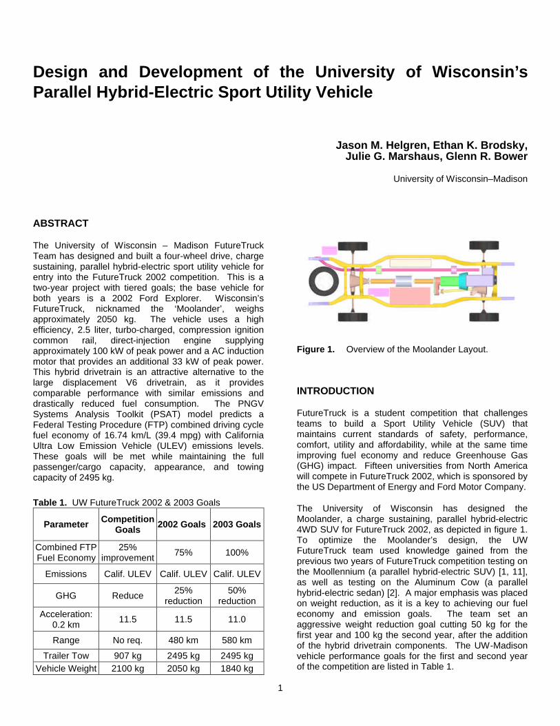
The University of Wisconsin has designed the Moolander, a charge sustaining, parallel hybrid-electric 4WD SUV for FutureTruck 2002, as depicted in figure 1. To optimize the Moolander’s design, the UW FutureTruck team used knowledge gained from the previous two years of FutureTruck competition testing on the Moollennium (a parallel hybrid-electric SUV) [1, 11], as well as testing on the Aluminum Cow (a parallel hybrid-electric sedan) [2]. A major emphasis was placed on weight reduction, as it is a key to achieving our fuel economy and emission goals. The team set an aggressive weight reduction goal cutting 50 kg for the first year and 100 kg the second year, after the addition of the hybrid drivetrain components. The UW-Madison vehicle performance goals for the first and second year of the competition are listed in Table 1.
Table 1. UW FutureTruck 2002 & 2003 Goals
Parameter Competition Goals 2002 Goals 2003 Goals
Combined FTP Fuel Economy
25% improvement 75% 100%
Emissions Calif. ULEV Calif. ULEV Calif. ULEV
GHG Reduce 25% reduction
50% reduction
Acceleration: 0.2 km 11.5 11.5 11.0
Range No req. 480 km 580 km
Trailer Tow 907 kg 2495 kg 2495 kg Vehicle Weight 2100 kg 2050 kg 1840 kg
Figure 1. Overview of the Moolander Layout.
2
TEAM ORGANIZATION
The UW FutureTruck team consists of seven groups: Mechanical, Electrical, Engine, Controls, Telematics, Business, and Information (team composition is shown in Table 2). These seven groups are overseen by a faculty advisor and a student team leader. A team RADAR acts as a liaison between the competition organizers and the UW team. There are approximately 40 team members, 15 of whom are participating in the FutureTruck project for course credit. Two team members are graduate students.
Each group is headed by a group leader. The group leaders are responsible for providing team members with guidance as well as planning and assigning projects. Group leaders are also responsible for setting and meeting project completion deadlines. The team leader oversees all of the groups to ensure that projects are completed as planned and facilitates communication between groups for multidisciplinary projects. The faculty advisor gives guidance, answers technical questions, and promotes relationships with industry.
Figure 2 is a general timeline compiled from the project completion date goals of the groups. In preparation for competition in June of 2002, the team has successfully achieved milestones depicted on the timeline.
ENERGY AND EMISSION REVIEW
In conjunction with the PNGV program, several renowned scientists have examined viable power sources for personnel transportation. These ‘well to wheels’ analyses consider the global impact of each energy source as well as its local impact from the tailpipe emissions.
A 1998 study, “Societal Impact of Fuel Options of Fuel Cell Vehicles”, [5] considered various fuels and vehicle configurations. It concluded that there were no clear winners that “The optimum fuel and optimum vehicle depend on the priority given to societal objectives…. If reduced greenhouse gases is the sole criterion, then the clear winners are natural gas or diesel parallel hybrids, with diesel parallel hybrids providing almost 15% lower greenhouse gas emissions than a direct hydrogen FCV [Fuel Cell Vehicle],….”
“On the Road in 2020” [10], a study conducted by the Massachusetts Institute of Technology, provides a framework for defining the best future power source as the effects of global warming and local air quality standards are quantified. “Vehicles with hybrid propulsion systems using either ICE [Internal Combustion Engine] or fuel cell power plants are the most efficient and lowest emitting technologies assessed. In general, ICE hybrids appear to have advantages over fuel cell hybrids with respect to life cycle GHG emissions, energy efficiency, and vehicle cost, ….”
After reviewing relevant literature, the UW team eliminated natural gas hybrids because of their inability to store enough gaseous fuel to satisfy vehicle range requirements. A series hybrid configuration was eliminated because it is not well suited for trailer towing. Also, the additional space and weight needed for its implementation would reduce the cargo capacity. As one of the main goals of FutureTruck 2002 is to reduce greenhouse gas emissions, the University of Wisconsin-Madison FutureTruck team chose to continue its research with compression ignition parallel hybrids.
KEYS TO INCREASING FUEL ECONOMY
A rudimentary model of energy requirements for a vehicle was developed [3]. This is a very simple model that does not include engine efficiency and electric motor efficiency, but gives insight into how the major parameters affect fuel economy. The UW-Madison team also used the PSAT model, which is an all-inclusive model including individual component efficiencies. Fuel economy modeling done with PSAT will be discussed later.
Table 2. Team Composition by Major.
Mechanical Engineering 60%
Electrical and Computer Engineering 20%
Industrial Engineering 4%
Materials Science 3%
Computer Science 8%
Other 5%
Figure 2. UW-Madison FutureTruck 2002 & 2003 project timeline.

3
(1) Proad = Proll + Phill + Paero + Paccel + Paux
(2) Proll = m g V Crr cos θ
(3) Phill = m g V sin θ
(4) Paero = 0.5 ρ A V3 Cd
(5) Paccel = d Ekinetic / dt = m V dV / dt
(6) Paux = f (alternator, power steering, etc.)
The road power demand Equation (1) identifies the vehicle design aspects that can be changed to improve the overall energy efficiency of the vehicle. The relative effect of reducing each parameter is depicted in figure 3 in terms of the fuel economy impact over the FTP 75 cycle for a conventional vehicle [4]. It is clear from the figure that vehicle mass is the dominant factor in vehicle energy consumption. Therefore, weight reduction was given the highest design priority.
CONVENTIONAL DRIVETRAIN COMPONENTS
Components exactly matching ‘ideal’ specifications are rarely obtainable; therefore, component availability was a dominating constraint as the team searched for a desirable combination of engine, transmission, and electric drive system. The UW team researched and identified viable component options for integration into the 2002 UW FutureTruck.
When searching for components, American manufacturers were considered first. This was done to minimize lead times and increase the feasibility of manufacturing the Moolander domestically.
Throughout the selection process, appropriately sized components were chosen to maximize energy efficiency and minimize weight. A packaging diagram of the Moolander is shown in figure 4.
Engine – With the aforementioned constraints in mind, the Wisconsin team searched for an acceptable common rail compression ignition direct-injection (CIDI) engine for its 2002 FutureTruck.
The IC engine must be sized to meet the largest continuous power demand the vehicle will experience. This occurs during towing. To meet the competition towing requirement, a minimum engine power of 65 kW (87 hp) is required. This value is based on the power required to travel up a 5% grade at 89 km/hr (55 mph) while pulling a 907 kg trailer. To meet the team’s goal of maintaining stock trailer towing capability (2495 kg), 92 kW (123 hp) is required from the engine (figure 5). This graph was generated using the power equations described in the ‘Keys to Increasing Fuel Economy’ section.
100 kW TDI Engine
5 speed Transmission
Transfer Case
33 kW Motor
High Voltage Interface
1.78 kW-hr NiMH Battery
78 kW Inverter
Fuel Tank 30.3 L
Figure 4. Packaging diagram for the Moolander.
20 40 60 80 100 1200
25
50
75
100
125
150
Req
uire
d P
ower
(kW
)
Vehicle Speed (km/hr)
5% grade, zero head wind, with 2495 kg Trailer 5% grade, zero head wind, with 907 kg Trailer 1% grade, 48 km/hr head wind, with 907 kg Trailer 1% grade, 48 km/hr head wind, with 2495 kg Trailer Land Rover Engine Power (100 kW)
Figure 5. Power requirements for the Moolander to tow a 907 kg and a 2495 kg trailer under different conditions.
0 10 20 30 40 501.00
1.05
1.10
1.15
1.20
1.25
1.30
EP
A C
ombi
ned
Fue
l Eco
nom
y M
agni
tude
Parameter Reduction (%)
Mass Aero Tires Accessories
Figure 3. Fuel economy gain vs. parameter reduction.
4
As traditional transmissions have discrete gear ratios, it is imperative that the peak trailer tow power requirement can be achieved throughout the upper 25% of the engine’s operating range (1000 rpm band) because engines cannot be operated at peak power under all conditions. Due to the torque-rise characteristic of the CIDI engine, a 25% peak power margin will ensure that power demands can be achieved during extended hill climbs.
Ideal midrange diesels that provide the optimal power are currently unavailable domestically. An increase over the ideal engine size would consume more fuel and increase vehicle weight, defeating the purpose of a hybrid vehicle. Therefore, it was determined that a midsize European CIDI engine would best suit the hybrid powertrain design of the University of Wisconsin team. Table 3 lists the engines that were considered.
The 2.5L LandRover was used in the Moollennium for FutureTruck 2001. This engine provided excellent low-end torque and a relatively flat torque curve. In addition to its favorable torque characteristics, the inline 5-cylinder, turbo-charged, common rail, CIDI engine has a maximum thermal efficiency of 42%. This engine has more than enough torque to meet the FutureTruck 2002 competition requirements and will ensure that the UW team’s performance goals are met. A complete list of the engine specifications are shown in Table 4.
Transmission – The Wisconsin FutureTruck team has chosen to use a manual transmission because of the inherent high efficiency, low mass, and control flexibility of this type of transmission. Since all drivers do not desire manual transmissions, a hydraulic auto-shift unit could be an option in a production vehicle. The auto-
shift manual transmission is a proven design, which has been incorporated into many high-end European vehicles. The UW FutureTruck team chose not to integrate an auto-shifting feature with the manual transmission to reduce drivetrain control complexity.
Two manual transmission options were considered for the Moolander. The first option was the Richmond Gear transmission used in the Moollennium for FutureTruck 2001. This transmission is a high performance racing transmission designed for high-torque applications. It performed very well in the Moollennium, but due to the side mounted rod shifters and packaging constraints, designing a reliable shifting system proved difficult. The second option was a 5-speed Borg Warner transmission. This transmission has been in service for over 20 years and is readily available. The top-load shifter aligned with the stock Explorer shifter access panel and would produce the quietest, smoothest shifting option. In addition, the Borg Warner option was 20 kg lighter than the Richmond transmission.
The Borg Warner World Class T5 transmission containing an integral reverse gear was chosen as the best option for the Moolander. The gear ratios are shown in Table 5. Lower gear ratios were selected for 1st – 4th gear to provide additional low-end torque to aid in towing capabilities. High-end gearing for 5th gear has been chosen to optimize engine efficiency during highway driving. The placement of the transmission in the Wisconsin FutureTruck is displayed in the packaging diagram (figure 4).
Table 3. Engine Comparison Engine Type
Power (kW)
Torque (Nm)
Weight (kg)
Deciding Factors
2.5L Land Rover Td5 100 325 249 Available &
Tested 2.0L Land
Rover 82 260 187 Not Available
1.8L Ford Lynx TDCi 90 250 158 Not Immediately
Available
2.4L Ford Puma
92 285 220 Unacceptable Power/ Torque
Table 4. Engine Build Details for the 2.5L Td5 LandRover Engine. Engine Component Specification Rated Power 100 kW at 4200 rpm Maximum Torque 325 Nm @ 1950 rpm Speed Range 1000 – 4800 rpm Bore 90.47 mm Stroke 97.0 mm Displacement 2495 cc Control System Land Rover ECM
Table 5. Gear Ratios for Borg Warner Transmission.
Gear Ratio 1st 3.97:1 2nd 2.34:1 3rd 1.46:1 4th 1.0:1 5th 0.79:1
Reverse 3.70:1
Differential 3.73:1
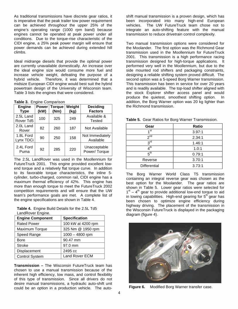
Figure 6. Modified Borg Warner transfer case.
5
Hybrid Transfer Case – The UW-Madison team developed a custom single-speed silent chain transfer case by modifying a stock Borg Warner 1354 transfer case. The 1354 has been utilized in the Ford Ranger for the last decade. To save weight and space while reducing driveline losses, the low-range section of the transfer case was eliminated.
The 2001 Moollennium drive train featured an all-in-one, inline drive train consisting of the engine, transmission, transfer case, and through-shaft electric motor. In addition to interfering with the stock shifting components, this design had significant noise vibration harshness (NVH) issues because of the direct linkage between all components. In order to reduce these effects in 2002 the decision was made to use a ‘divorced’ motor. Only one half of the transfer case required modification; the mounting holes were rotated to locate the transfer case on the passenger side of the vehicle to allow room for the exhaust. A new enclosure was CNC machined from billet aluminum. The stock Explorer shifting motor and controls are utilized to shift from 2WD to 4WD.
Fuel Tank – A single fuel tank, holding 30.28 liters, is required by the competition rules. This will provide a ‘tank’ range of 480 km. The tank is constructed from 1.27 mm thick 5052 H32 aluminum with TIG-welded seams. The tank uses the stock Land Rover in-line lift pump/filter to transport the fuel to the engine. The fuel system is compatible with both regular diesel and biodiesel fuel.
ELECTRIC DRIVE SYSTEM
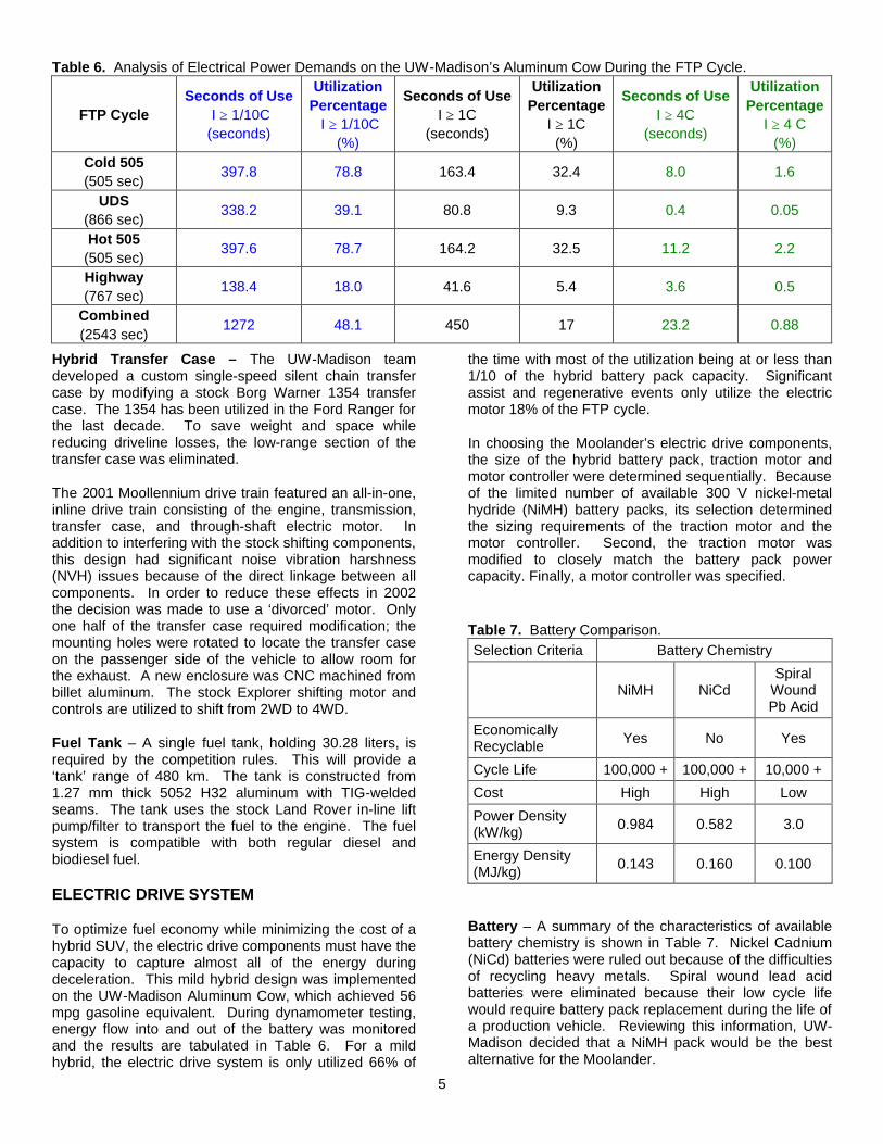
To optimize fuel economy while minimizing the cost of a hybrid SUV, the electric drive components must have the capacity to capture almost all of the energy during deceleration. This mild hybrid design was implemented on the UW-Madison Aluminum Cow, which achieved 56 mpg gasoline equivalent. During dynamometer testing, energy flow into and out of the battery was monitored and the results are tabulated in Table 6. For a mild hybrid, the electric drive system is only utilized 66% of
the time with most of the utilization being at or less than 1/10 of the hybrid battery pack capacity. Significant assist and regenerative events only utilize the electric motor 18% of the FTP cycle.
In choosing the Moolander’s electric drive components, the size of the hybrid battery pack, traction motor and motor controller were determined sequentially. Because of the limited number of available 300 V nickel-metal hydride (NiMH) battery packs, its selection determined the sizing requirements of the traction motor and the motor controller. Second, the traction motor was modified to closely match the battery pack power capacity. Finally, a motor controller was specified.
Battery – A summary of the characteristics of available battery chemistry is shown in Table 7. Nickel Cadnium (NiCd) batteries were ruled out because of the difficulties of recycling heavy metals. Spiral wound lead acid batteries were eliminated because their low cycle life would require battery pack replacement during the life of a production vehicle. Reviewing this information, UW-Madison decided that a NiMH pack would be the best alternative for the Moolander.
Table 7. Battery Comparison. Selection Criteria Battery Chemistry
NiMH NiCd
Spiral Wound Pb Acid
Economically Recyclable Yes No Yes
Cycle Life 100,000 + 100,000 + 10,000 +
Cost High High Low
Power Density (kW/kg) 0.984 0.582 3.0
Energy Density (MJ/kg) 0.143 0.160 0.100
Table 6. Analysis of Electrical Power Demands on the UW-Madison’s Aluminum Cow During the FTP Cycle.
FTP Cycle Seconds of Use
I ≥ 1/10C (seconds)
Utilization Percentage I ≥ 1/10C
(%)
Seconds of Use I ≥ 1C
(seconds)
Utilization Percentage
I ≥ 1C (%)
Seconds of Use I ≥ 4C
(seconds)
Utilization Percentage
I ≥ 4 C (%)
Cold 505 (505 sec)
397.8 78.8 163.4 32.4 8.0 1.6
UDS (866 sec)
338.2 39.1 80.8 9.3 0.4 0.05
Hot 505 (505 sec)
397.6 78.7 164.2 32.5 11.2 2.2
Highway (767 sec)
138.4 18.0 41.6 5.4 3.6 0.5
Combined (2543 sec)
1272 48.1 450 17 23.2 0.88
6
Historically, appropriately sized nickel based batteries for mild hybrid designs are not commercially available. UW-Madison has previously addressed this issue by packaging hundreds of NiMH sub-C cells. For the projected mass of the Moolander, a pack regenerative power capacity of approximately 45 kW was established.
Three different options were considered: a prototype pack consisting of either 720 (three parallel strings) or 960 (four parallel strings) Moltech Power Systems sub-C batteries or a production battery pack made up of Panasonic prismatic cells used in the Toyota Prius. Table 8 summarizes their specifications. Because of the assembly technique, the prismatic cells have a 25% power density advantage – the single most important factor for a mild hybrid. In addition to its power density advantage, the Prius battery pack was pre-assembled, designed for hybrid vehicle use, and was volumetrically 30% smaller than any other option.
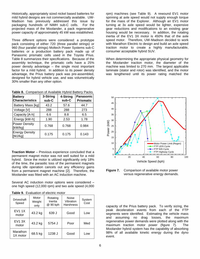
Traction Motor – Previous experience concluded that a permanent magnet motor was not well suited for a mild hybrid. Since the motor is utilized significantly only 18% of the time, the parasitic loss of the permanent magnets during idle operation cancels out any efficiency gains from a permanent magnet machine [2]. Therefore, the Moolander was fitted with an AC induction machine.
Several AC induction motor options were considered – one high speed (12,000 rpm) and two axle speed (4,000
rpm) machines (see Table 9). A rewound EV1 motor spinning at axle speed would not supply enough torque for the mass of the Explorer. Although an EV1 motor turning at 3x axle speed would be lighter, expensive gear reductions and modifications to an existing gear housing would be necessary. In addition, the rotating inertia of the EV1 3X motor is 450% that of the axle speed motor. Therefore, UW-Madison decided to work with Marathon Electric to design and build an axle speed traction motor to create a highly manufacturable, consumer acceptable hybrid SUV.
When determining the appropriate physical geometry for the Moolander traction motor, the diameter of the machine was limited to 270 mm. The largest applicable laminate (stator and rotor) was identified, and the motor was lengthened until its power rating matched the
capacity of the Prius battery pack. To verify sizing, the peak deceleration events from each of the FTP segments were identified. Estimating the vehicle mass and assuming no drag losses, the maximum regenerative power demands were plotted along with the maximum traction motor power (figure 7). The Moolander hybrid system has the capability of absorbing 98% of all available kinetic energy during the dyno event.
0 20 40 60 80 1000
5
10
15
20
25
30
35
40
45
50
Pow
er (
kW)
Vehicle Speed (kph)
Motor Power Limit (Regen) FTP UDS Cycle FTP 505 Cycle FTP Highway Cycle
Figure 7. Comparison of available motor power
versus regenerative energy demands.
Table 9. Evaluation of electric motor
Driveshaft Speed
Motor Weight
only
Rotating Inertia
@ 90 kph
Noise Vibration
Harshness
System Cost
EV1 1X motor 43.2 kg 639 J Good Low
EV1 3X motor 43.2 kg 5754 J Poor Med
Marathon 1X motor 68.5 kg 1238 J Good Low
Table 8. Comparison of Available Hybrid Battery Packs. Battery Characteristics
3-String sub-C
4-String sub-C
Panasonic Prismatic
Battery Mass [kg] 43.2 57.6 44.7 Voltage [V] 288 288 273 Capacity [A-h] 6.6 8.8 6.5 Energy [kW-h] 1.90 2.53 1.78 Power Density [kW/kg] 0.768 0.768 0.984
Energy Density [MJ/kg] 0.175 0.175 0.143
7
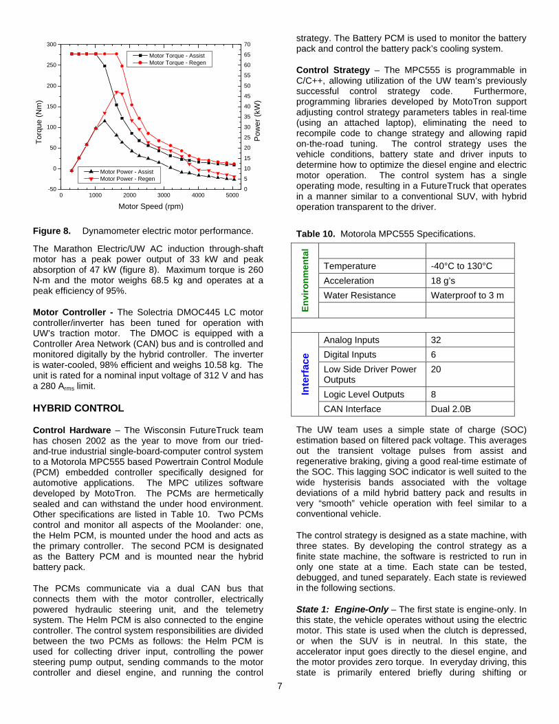
The Marathon Electric/UW AC induction through-shaft motor has a peak power output of 33 kW and peak absorption of 47 kW (figure 8). Maximum torque is 260 N-m and the motor weighs 68.5 kg and operates at a peak efficiency of 95%.
Motor Controller - The Solectria DMOC445 LC motor controller/inverter has been tuned for operation with UW’s traction motor. The DMOC is equipped with a Controller Area Network (CAN) bus and is controlled and monitored digitally by the hybrid controller. The inverter is water-cooled, 98% efficient and weighs 10.58 kg. The unit is rated for a nominal input voltage of 312 V and has a 280 Arms limit.
HYBRID CONTROL
Control Hardware – The Wisconsin FutureTruck team has chosen 2002 as the year to move from our tried-and-true industrial single-board-computer control system to a Motorola MPC555 based Powertrain Control Module (PCM) embedded controller specifically designed for automotive applications. The MPC utilizes software developed by MotoTron. The PCMs are hermetically sealed and can withstand the under hood environment. Other specifications are listed in Table 10. Two PCMs control and monitor all aspects of the Moolander: one, the Helm PCM, is mounted under the hood and acts as the primary controller. The second PCM is designated as the Battery PCM and is mounted near the hybrid battery pack.
The PCMs communicate via a dual CAN bus that connects them with the motor controller, electrically powered hydraulic steering unit, and the telemetry system. The Helm PCM is also connected to the engine controller. The control system responsibilities are divided between the two PCMs as follows: the Helm PCM is used for collecting driver input, controlling the power steering pump output, sending commands to the motor controller and diesel engine, and running the control
strategy. The Battery PCM is used to monitor the battery pack and control the battery pack’s cooling system.
Control Strategy – The MPC555 is programmable in C/C++, allowing utilization of the UW team’s previously successful control strategy code. Furthermore, programming libraries developed by MotoTron support adjusting control strategy parameters tables in real-time (using an attached laptop), eliminating the need to recompile code to change strategy and allowing rapid on-the-road tuning. The control strategy uses the vehicle conditions, battery state and driver inputs to determine how to optimize the diesel engine and electric motor operation. The control system has a single operating mode, resulting in a FutureTruck that operates in a manner similar to a conventional SUV, with hybrid operation transparent to the driver.
The UW team uses a simple state of charge (SOC) estimation based on filtered pack voltage. This averages out the transient voltage pulses from assist and regenerative braking, giving a good real-time estimate of the SOC. This lagging SOC indicator is well suited to the wide hysterisis bands associated with the voltage deviations of a mild hybrid battery pack and results in very “smooth” vehicle operation with feel similar to a conventional vehicle.
The control strategy is designed as a state machine, with three states. By developing the control strategy as a finite state machine, the software is restricted to run in only one state at a time. Each state can be tested, debugged, and tuned separately. Each state is reviewed in the following sections.
State 1: Engine-Only – The first state is engine-only. In this state, the vehicle operates without using the electric motor. This state is used when the clutch is depressed, or when the SUV is in neutral. In this state, the accelerator input goes directly to the diesel engine, and the motor provides zero torque. In everyday driving, this state is primarily entered briefly during shifting or
0
5
10
15
20
25
30
35
40
45
50
55
60
65
70
0 1000 2000 3000 4000 5000-50
0
50
100
150
200
250
300
Pow
er (
kW)
Motor Power - Assist Motor Power - Regen
T
orqu
e (N
m)
Motor Speed (rpm)
Motor Torque - Assist Motor Torque - Regen
Figure 8. Dynamometer electric motor performance. Table 10. Motorola MPC555 Specifications.
Temperature -40°C to 130°C
Acceleration 18 g’s
Water Resistance Waterproof to 3 m E
nvi
ron
men
tal
Analog Inputs 32
Digital Inputs 6
Low Side Driver Power Outputs
20
Logic Level Outputs 8 Inte
rfac
e
CAN Interface Dual 2.0B
8
“launch” from a complete stop. For longer periods, the engine may be completely shut down, as discussed later in the “Idle Stop” section.
State 2: Regenerative Braking – The second state is the regenerative braking state. Regenerative braking (regen) is the act of using the mechanical energy from the wheels to drive the motor, generating electricity for storage in the battery. This process recharges the battery while decreasing the vehicle speed. The vehicle goes into the regenerative braking state only if the brake pedal is depressed and the battery pack is not excessively charged. The brake pedal travel is split into two portions. The first 2 cm of travel does not engage the hydraulic brakes – only regenerative braking is used. After 2 cm, regenerative braking is fully saturated and the stock hydraulic brakes engage to help slow the vehicle. This allows the driver to regenerate large amounts of kinetic energy during braking, which increases fuel economy in stop-and-go driving. At the same time, ‘hard’ braking must still cause the conventional brakes to invoke the ABS system.
The goal of the regen brake system is to maintain ‘normal’ brake pedal feel during regen events. This year, small orifices are being added to the internal bore of the master cylinder with relief to the brake fluid reservoir. Relief holes are being added to the front and rear chambers so that the original brake biasing is maintained. The holes are being positioned so that a slow depression of the brake pedal allows 25 mm of pedal travel before the conventional brakes are activated. If the holes are sized appropriately, fluid flow will be restricted and rapid activation of the brake pedal will cause the brake line pressure to rise during the first 25 mm of travel. Under slow depression, the fluid will be relieved and the regenerative system will provide the majority of the braking. The control system measures the brake pedal position using a rotary potentiometer mounted on the pedal and adjusts the regenerative braking level accordingly.
State 3: HEV – The HEV state is the third and most common state in the control strategy. This state contains the battery SOC regulating control code, which attempts to keep the battery SOC between 20% and 80% for optimal operation (below 20%, the battery is incapable of delivering useful assist power, and while above 80%, the battery cannot efficiently absorb adequate regen power). The HEV state implements an internal hysteresis-based state machine that, based on SOC, switches between several curves specifying engine/motor torque versus pedal position. The strategy behavior is filtered during state transitions to give seamless, smooth operation. The use of multiple transfer functions allows the strategy to automatically adapt to maintain SOC for different styles of driving.
Safety is ensured by range checking all inputs and outputs. If a value entering or leaving the hybrid control system is too low or too high, the control system will
adjust the value to the closest bound, or, if the values are far out of range (indicating a serious hardware error), the control strategy will disable the electric motor to prevent hazardous operation.
To further improve fuel economy in city driving and reduce GHG emissions, the control strategy implements intermittent engine operation. When the driver does not need the engine (for example, when coasting or stopped at a red light), the control strategy shuts the engine down. The engine is automatically restarted when it is needed again. This technique has been successfully demonstrated in the Aluminum Cow and will be discussed later in the paper.
ENVIRONMENTAL IMPACT
Greenhouse Gas – Reducing GHG is a global initiative and a primary goal of the FutureTruck competition. The EPA has developed a standardized method to quantify the greenhouse gas index (GHGI), which uses the following formula:
(7) GHGI = CO2 + 21*CH4 + 310*N2O For any ICE, CO2, the dominant GHGI contributor, is directly related to the quantity of fuel consumed. Once a fuel is determined, the only way to minimize CO2 emissions from an engine is to maximize fuel economy. This was one of the primary reasons for selecting CIDI.
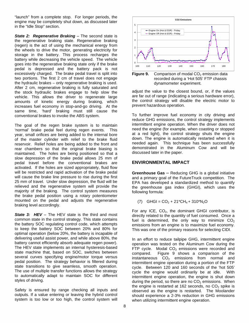
In an effort to reduce tailpipe GHG, intermittent engine operation was tested on the Aluminum Cow during the FTP cycle. Modal CO2 emissions were recorded and compared. Figure 9 shows a comparison of the instantaneous CO2 emissions from normal and intermittent engine operation during a portion of the FTP cycle. Between 120 and 160 seconds of the ‘hot 505’ cycle the engine would ordinarily be at idle. With intermittent engine operation, the engine is shut down during the period, so there are no CO2 emissions. When the engine is restarted at 162 seconds, no CO2 spike is observed as the engine is restarted. The Moolander should experience a 2-3% reduction in GHG emissions when utilizing intermittent engine operation.
CO2 Emissions
0
1
2
3
4
5
100 110 120 130 140 150 160 170 180
Engine On (Hot & EGR) - FridayEngine Off (Hot & EGR) - Friday
Figure 9. Comparison of modal CO2 emission data recorded during a ‘Hot 505’ FTP chassis dynamometer experiment.
9
The other technique for reducing GHG is to use an alternative fuel source which has a large GHG credit. The GHG credit accounts for CO2 recaptured annually by soybeans, corn, or rape seed used in producing the fuel. For CIDI applications, the only renewable alternative is a blend of 50% biodiesel. Since biodiesel is an oxygenated fuel, there is a slight energy density penalty. When comparing standard diesel fuel to a typical soybean based B-50 blend [8], the engine power will be reduced by 4.2% while decreasing GHG by 35%. For the aforementioned reasons, the Moolander will be a grain-fed hybrid SUV.
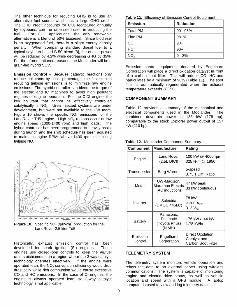
Emission Control – Because catalytic reactions only reduce pollutants by a set percentage, the first step to reducing tailpipe emissions is to minimize raw engine emissions. The hybrid controller can blend the torque of the electric and IC machines to avoid high pollutant regimes of engine operation. For the CIDI engine, the key pollutant that cannot be effectively controlled catalytically is NOx. Urea injected systems are under development, but were not available to the UW team. Figure 10 shows the specific NOx emissions for the LandRover Td5 engine. High NOx regions occur at low engine speed (1000-1400 rpm) and high loads. The hybrid controller has been programmed to heavily assist during launch and the shift schedule has been adjusted to maintain engine RPMs above 1400 rpm, minimizing tailpipe NOx.
Historically, exhaust emission control has been developed for spark ignition (SI) engines. These engines use closed-loop controls to keep the air/fuel ratio stoichiometric, in a region where the 3-way catalyst technology operates effectively. If the engine were operated lean, the NOx conversion efficiency would drop drastically while rich combustion would cause excessive CO and HC emissions. In the case of CI engines, the engine is always operated lean, so 3-way catalyst technology is not applicable.
Emission control equipment donated by Engelhard Corporation will place a direct oxidation catalyst in front of a carbon soot filter. This will reduce CO, HC and particulates by a minimum of 90% (Table 11). The soot filter is automatically regenerated when the exhaust temperature exceeds 385° C.
COMPONENT SUMMARY
Table 12 provides a summary of the mechanical and electrical components used in the Moolander. The combined drivetrain power is 133 kW (178 hp), comparable to the stock Explorer power output of 157 kW (210 hp).
TELEMETRY SYSTEM
The telemetry system monitors vehicle operation and relays the data to an external server using wireless communications. The system is capable of monitoring engine and electric drive status, as well as vehicle location and speed with a GPS module. A laptop computer is used to view and log telemetry data.
Table 12. Moolander Component Summary.
Component Manufacturer Rating
Engine Land Rover (2.5L DICI)
100 kW @ 4000 rpm 325 N-m @ 1950
Transmission Borg Warner 5-speed 3.73:1 Diff. Ratio
Motor UW-Madison/
Marathon Electric (AC induction)
47 kW peak 33 kW continuous
Inverter Solectria (DMOC 445LC)
78 kW ≤ 280 Arms
312 Vdc
Battery
Panasonic Prismatic
(Toyota Prius) (NiMH)
+76 kW / -44 kW 1.78 kWhr
Emission Control
Engelhard Corporation
Direct Oxidation Catalyst and Carbon Soot Filter
Table 11. Efficiency of Emission Control Equipment
Emission Reduction
Total PM 90 - 95%
Fine PM 98+%
CO 90+
HC 90+
NOx 0 - 3%
Figure 10. Specific NOx (g/kWhr) production for the LandRover 2.5 liter Td5.
10
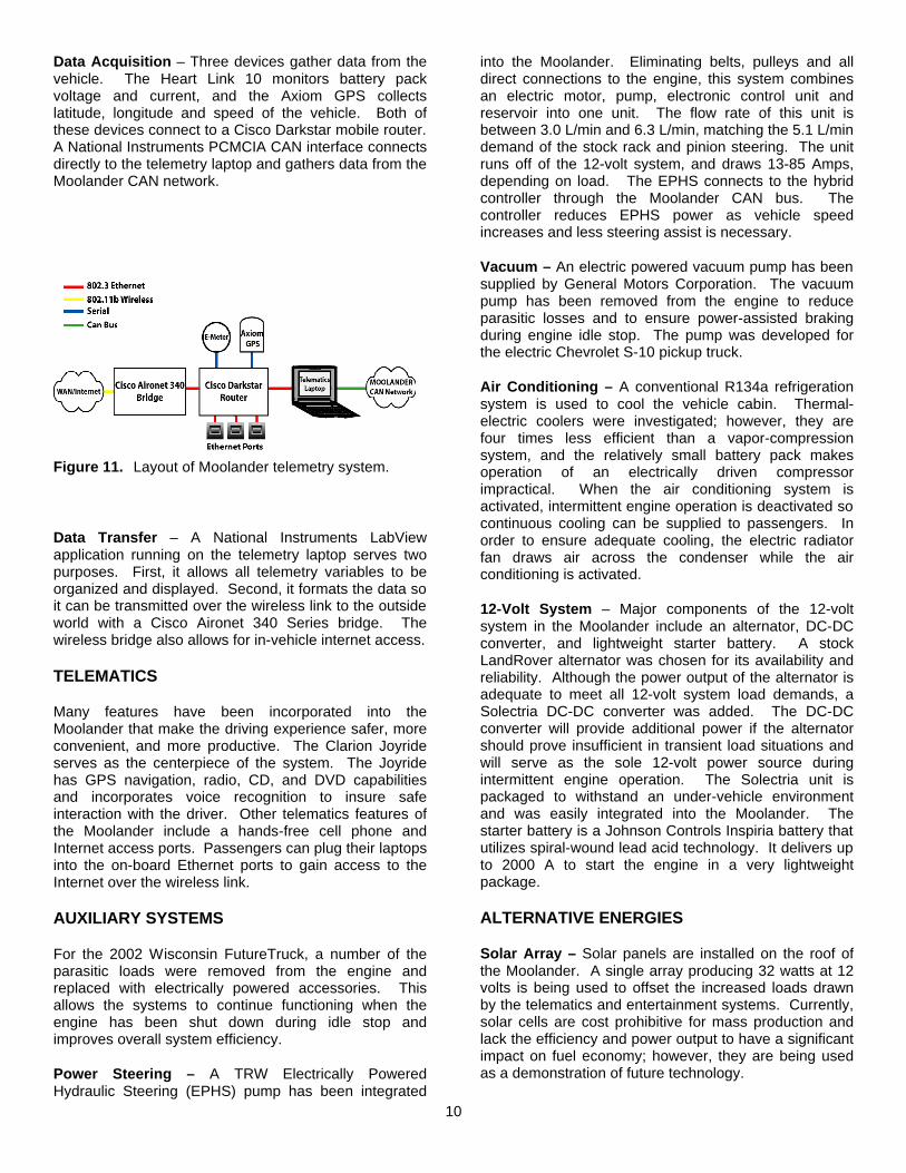
Data Acquisition – Three devices gather data from the vehicle. The Heart Link 10 monitors battery pack voltage and current, and the Axiom GPS collects latitude, longitude and speed of the vehicle. Both of these devices connect to a Cisco Darkstar mobile router. A National Instruments PCMCIA CAN interface connects directly to the telemetry laptop and gathers data from the Moolander CAN network.
Data Transfer – A National Instruments LabView application running on the telemetry laptop serves two purposes. First, it allows all telemetry variables to be organized and displayed. Second, it formats the data so it can be transmitted over the wireless link to the outside world with a Cisco Aironet 340 Series bridge. The wireless bridge also allows for in-vehicle internet access.
TELEMATICS
Many features have been incorporated into the Moolander that make the driving experience safer, more convenient, and more productive. The Clarion Joyride serves as the centerpiece of the system. The Joyride has GPS navigation, radio, CD, and DVD capabilities and incorporates voice recognition to insure safe interaction with the driver. Other telematics features of the Moolander include a hands-free cell phone and Internet access ports. Passengers can plug their laptops into the on-board Ethernet ports to gain access to the Internet over the wireless link.
AUXILIARY SYSTEMS
For the 2002 Wisconsin FutureTruck, a number of the parasitic loads were removed from the engine and replaced with electrically powered accessories. This allows the systems to continue functioning when the engine has been shut down during idle stop and improves overall system efficiency.
Power Steering – A TRW Electrically Powered Hydraulic Steering (EPHS) pump has been integrated
into the Moolander. Eliminating belts, pulleys and all direct connections to the engine, this system combines an electric motor, pump, electronic control unit and reservoir into one unit. The flow rate of this unit is between 3.0 L/min and 6.3 L/min, matching the 5.1 L/min demand of the stock rack and pinion steering. The unit runs off of the 12-volt system, and draws 13-85 Amps, depending on load. The EPHS connects to the hybrid controller through the Moolander CAN bus. The controller reduces EPHS power as vehicle speed increases and less steering assist is necessary.
Vacuum – An electric powered vacuum pump has been supplied by General Motors Corporation. The vacuum pump has been removed from the engine to reduce parasitic losses and to ensure power-assisted braking during engine idle stop. The pump was developed for the electric Chevrolet S-10 pickup truck.
Air Conditioning – A conventional R134a refrigeration system is used to cool the vehicle cabin. Thermal-electric coolers were investigated; however, they are four times less efficient than a vapor-compression system, and the relatively small battery pack makes operation of an electrically driven compressor impractical. When the air conditioning system is activated, intermittent engine operation is deactivated so continuous cooling can be supplied to passengers. In order to ensure adequate cooling, the electric radiator fan draws air across the condenser while the air conditioning is activated.
12-Volt System – Major components of the 12-volt system in the Moolander include an alternator, DC-DC converter, and lightweight starter battery. A stock LandRover alternator was chosen for its availability and reliability. Although the power output of the alternator is adequate to meet all 12-volt system load demands, a Solectria DC-DC converter was added. The DC-DC converter will provide additional power if the alternator should prove insufficient in transient load situations and will serve as the sole 12-volt power source during intermittent engine operation. The Solectria unit is packaged to withstand an under-vehicle environment and was easily integrated into the Moolander. The starter battery is a Johnson Controls Inspiria battery that utilizes spiral-wound lead acid technology. It delivers up to 2000 A to start the engine in a very lightweight package.
ALTERNATIVE ENERGIES
Solar Array – Solar panels are installed on the roof of the Moolander. A single array producing 32 watts at 12 volts is being used to offset the increased loads drawn by the telematics and entertainment systems. Currently, solar cells are cost prohibitive for mass production and lack the efficiency and power output to have a significant impact on fuel economy; however, they are being used as a demonstration of future technology.
Figure 11. Layout of Moolander telemetry system.
11
WEIGHT REDUCTION
In an effort to reduce the weight of the vehicle, many components were redesigned using lightweight materials, such as aluminum, or replaced with lighter stock components from other vehicles. According to the aluminum industry, a 20 percent weight reduction will increase fuel economy 12 to 16 percent. Over its lifetime, an aluminum-intensive vehicle would save 500 to 700 gallons (2,270 to 3,180 liters) of fuel, worth about $800 in the U.S., and three to four times that in Europe and Japan, over its lifetime. A more complete description of the benefits and uses of aluminum can be found in Appendix C.
Frame – The University of Wisconsin–Madison is in the process of fabricating an aluminum frame as a means of reducing the vehicle mass by 3-4%. The UW team is still working on forming industry partnership and the frame will not be completed in time for the 2002 FutureTruck competition. As an interim solution, a hybrid steel-aluminum frame (figure 12) has been developed which will utilize aluminum bumper beams
and crush zones while retaining the stock suspension mounting points. The methodologies and ideologies successfully implemented in the UW’s 430 and 830 aluminum frames designed for the 2000 Suburban [12], were implemented in the development of the UW 152 hybrid frame.
The front 12-inches of the steel frame has been removed and replaced with 5052 H34 aluminum crush zone. The front body mounts, an aluminum extruded bumper beam, and crush zones have been integrated into one component. To minimize the cost of repairs after minor accidents, the front section is now completely replaceable. Similarly, the rear 18-inches of the frame have been removed and replaced with 6061 T-6 aluminum extrusion. The rear bumper beam/trailer hitch and body mounts have been integrated into one component. In addition, the transmission, fuel tank and battery pack cross-members have been fabricated from 6061-T6 aluminum extrusions. The UW 152 frame design saves a total of 19 kg.
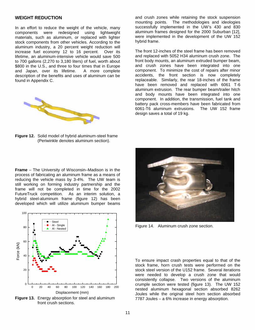
To ensure impact crash properties equal to that of the stock frame, horn crush tests were performed on the stock steel version of the U152 frame. Several iterations were needed to develop a crush zone that would consistently collapse. Two versions of the aluminum crumple section were tested (figure 13). The UW 152 nested aluminum hexagonal section absorbed 8262 Joules while the original steel horn section absorbed 7787 Joules – a 6% increase in energy absorption.
0 20 40 60 80 100 120 140 160 180 2000
20
40
60
80
100
For
ce (
kN)
Displacement (mm)
Steel Al - Single Al - Nested
Figure 13. Energy absorption for steel and aluminum front crush sections.
Figure 14. Aluminum crush zone section.
Figure 12. Solid model of hybrid aluminum-steel frame (Periwinkle denotes aluminum section).
12
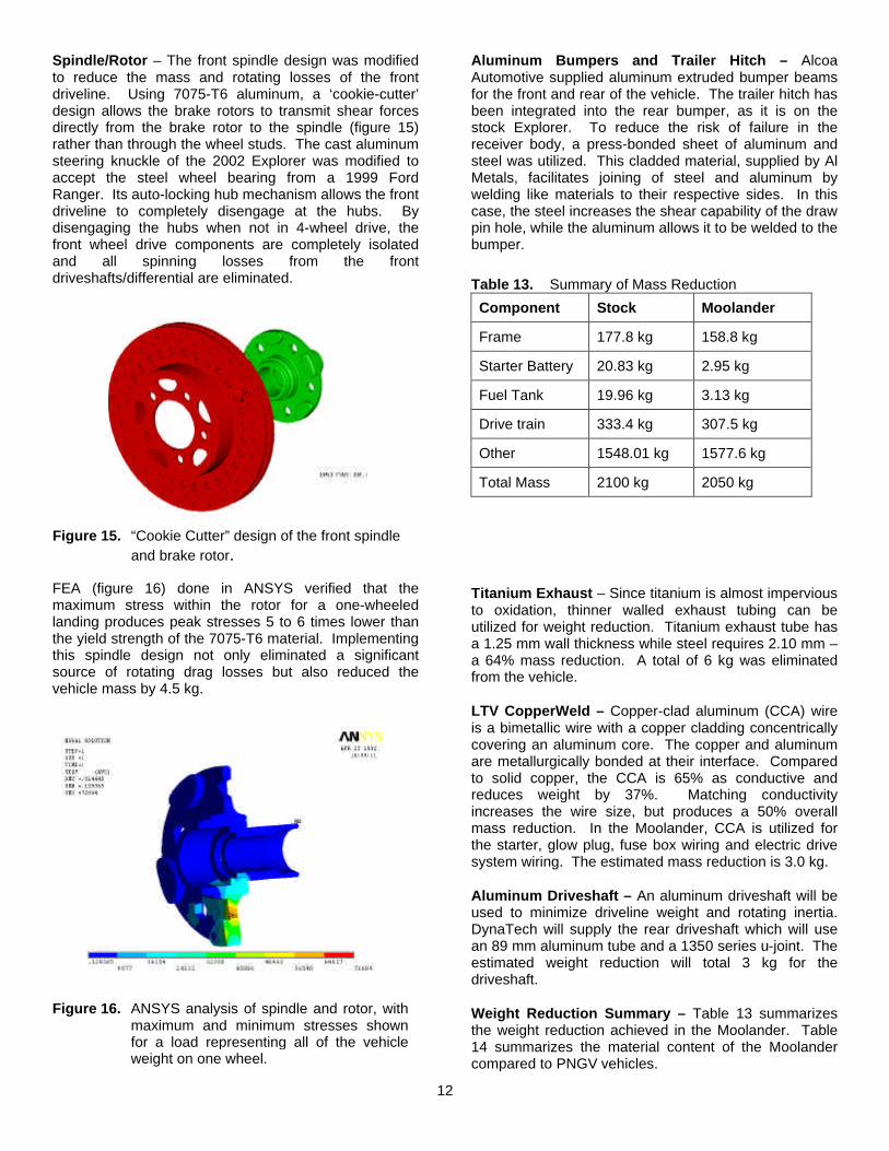
Spindle/Rotor – The front spindle design was modified to reduce the mass and rotating losses of the front driveline. Using 7075-T6 aluminum, a ‘cookie-cutter’ design allows the brake rotors to transmit shear forces directly from the brake rotor to the spindle (figure 15) rather than through the wheel studs. The cast aluminum steering knuckle of the 2002 Explorer was modified to accept the steel wheel bearing from a 1999 Ford Ranger. Its auto-locking hub mechanism allows the front driveline to completely disengage at the hubs. By disengaging the hubs when not in 4-wheel drive, the front wheel drive components are completely isolated and all spinning losses from the front driveshafts/differential are eliminated.
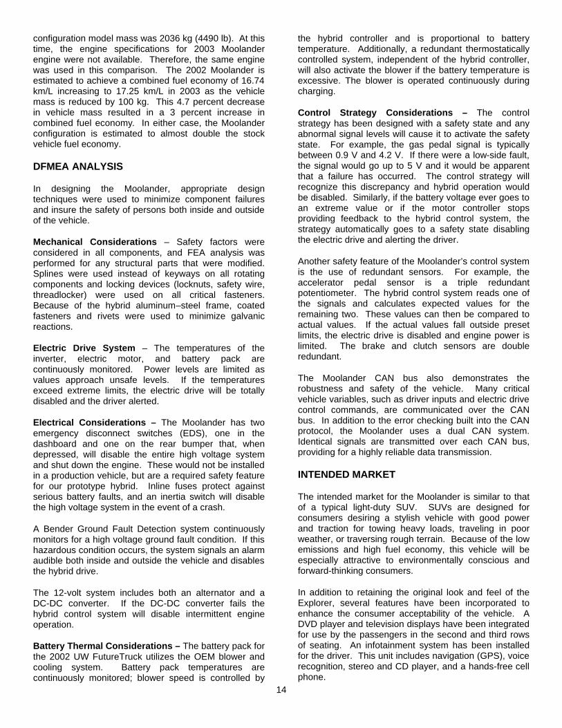
FEA (figure 16) done in ANSYS verified that the maximum stress within the rotor for a one-wheeled landing produces peak stresses 5 to 6 times lower than the yield strength of the 7075-T6 material. Implementing this spindle design not only eliminated a significant source of rotating drag losses but also reduced the vehicle mass by 4.5 kg.
Aluminum Bumpers and Trailer Hitch – Alcoa Automotive supplied aluminum extruded bumper beams for the front and rear of the vehicle. The trailer hitch has been integrated into the rear bumper, as it is on the stock Explorer. To reduce the risk of failure in the receiver body, a press-bonded sheet of aluminum and steel was utilized. This cladded material, supplied by Al Metals, facilitates joining of steel and aluminum by welding like materials to their respective sides. In this case, the steel increases the shear capability of the draw pin hole, while the aluminum allows it to be welded to the bumper.
Titanium Exhaust – Since titanium is almost impervious to oxidation, thinner walled exhaust tubing can be utilized for weight reduction. Titanium exhaust tube has a 1.25 mm wall thickness while steel requires 2.10 mm – a 64% mass reduction. A total of 6 kg was eliminated from the vehicle.
LTV CopperWeld – Copper-clad aluminum (CCA) wire is a bimetallic wire with a copper cladding concentrically covering an aluminum core. The copper and aluminum are metallurgically bonded at their interface. Compared to solid copper, the CCA is 65% as conductive and reduces weight by 37%. Matching conductivity increases the wire size, but produces a 50% overall mass reduction. In the Moolander, CCA is utilized for the starter, glow plug, fuse box wiring and electric drive system wiring. The estimated mass reduction is 3.0 kg.
Aluminum Driveshaft – An aluminum driveshaft will be used to minimize driveline weight and rotating inertia. DynaTech will supply the rear driveshaft which will use an 89 mm aluminum tube and a 1350 series u-joint. The estimated weight reduction will total 3 kg for the driveshaft.
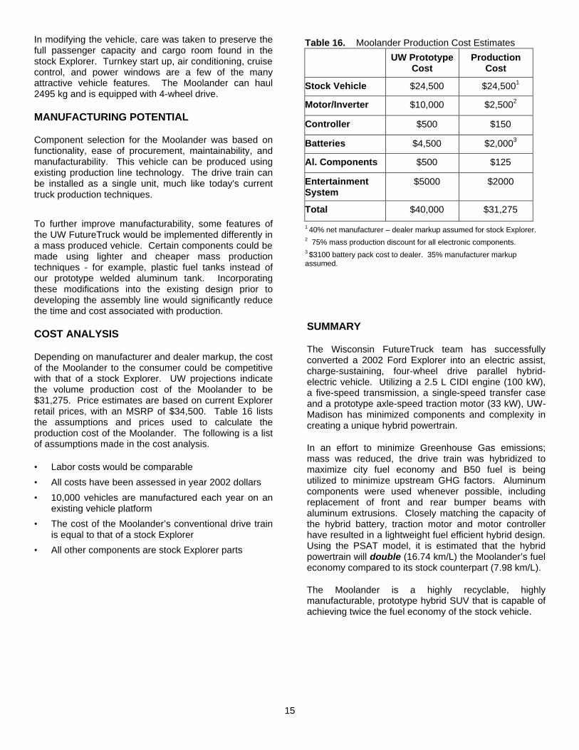
Weight Reduction Summary – Table 13 summarizes the weight reduction achieved in the Moolander. Table 14 summarizes the material content of the Moolander compared to PNGV vehicles.
Figure 16. ANSYS analysis of spindle and rotor, with
maximum and minimum stresses shown for a load representing all of the vehicle weight on one wheel.
Table 13. Summary of Mass Reduction
Component Stock Moolander
Frame 177.8 kg 158.8 kg
Starter Battery 20.83 kg 2.95 kg
Fuel Tank 19.96 kg 3.13 kg
Drive train 333.4 kg 307.5 kg
Other 1548.01 kg 1577.6 kg
Total Mass 2100 kg 2050 kg
Figure 15. “Cookie Cutter” design of the front spindle and brake rotor.

13
DRAG REDUCTION
As shown in Equation 4 of the Keys to Increasing Fuel Economy section, the second most significant factor that contributes to a vehicle’s power demand is aerodynamic drag. This loss is dependent on several factors; however, frontal area profile, drag coefficient, and rolling resistance are the only factors that can be influenced by design.
Ride Height Adjustment – The competition rules do not allow modification to the overall vehicle length or width, thus limiting the aerodynamic improvements that can be made. Lowering the overall height of the vehicle reduces the frontal area, which reduces the drag coefficient. The effects of lowering the vehicle were modeled in FLUENT (figure 17), a computational fluid dynamics analysis package. Using a 2-dimensional representation of the Explorer, FLUENT predicts a 15% reduction in aerodynamic drag for a 10 cm reduction in vehicle ride height. UW-Madison is investigating an active ride-height adjustment system for FutureTruck 2003.
Tires – Equation 2 shows that the vehicle power loss is directly related to the tires’ rolling resistance. The UW FutureTruck team has opted to use Goodyear’s low rolling resistance tires. The coefficient of rolling resistance is estimated to be 0.006 compared to the stock value of 0.010.
PSAT MODEL
The University of Wisconsin-Madison FutureTruck team utilized PSAT to estimate the performance characteristics of the Moolander. PSAT is a zero-dimensional forward-looking vehicle model, which operates within MATLAB v5.3 and Simulink v3. Each individual vehicle component/ parameter is characterized using a separate module. This allows each module to be modified and verified independently as parametric changes are implemented.
Modeling Approach – To verify the accuracy of PSAT, a stock V-6 Explorer 4x4 was modeled. As reviewed in Table 15, the PSAT urban fuel-economy prediction almost matched the published EPA values. The highway prediction was 12.8% low. Once the accuracy of the PSAT architecture was verified, a hybrid model of the Moolander was developed.
Modeling Results – Once a PSAT model was developed for the Moolander, the model was exercised to study the effects of different vehicle masses and shift schedules on fuel economy. It was quickly discovered that the shift schedule is predetermined by EPA protocol and therefore cannot be easily modified within PSAT. Finally, the Moolander configurations corresponding to the 2002 and planned 2003 vehicle configurations were compared. The 2002 configuration was modeled at a vehicle mass of 2136 kg (4700 lb), while the 2003
Figure 17. Aerodynamic drag modeling of the Ford
Explorer using FLUENT.
Table 15. PSAT Fuel Economy Results
Urban
(km/L)
Highway
(km/L)
EPA Composite
(km/L)
Stock Explorer
Published 7.09 10.90 8.41
Stock Explorer PSAT
7.06 9.50 7.98
Moolander PSAT 15.92 17.85 16.74
Table 14. Summary of Materials in the Moollennium versus a PNGV vehicle. Material % in PNGV
by Mass % in UW by Mass PNGV Mass (kg) UW Mass (kg)
Ferrous Metals 24.0 66.8 217.8 1370.1 Aluminum 37.0 12.8 332.5 265.0
Magnesium 4.3 0.04 39 0.8 Titanium 0.6 0.9 5 2.0 Plastic 13.0 11.6 122.0 238.2 Other 11.1 1.9 101 39.8
Rubber 6.0 3.9 55.8 79.5 Glass 1.8 2.6 16.3 52.4 Lexan 1.5 0.06 13.6 1.3
Carbon Fiber 0.3 0.04 3.6 0.9 Total Mass 100 100 907 2050
14
configuration model mass was 2036 kg (4490 lb). At this time, the engine specifications for 2003 Moolander engine were not available. Therefore, the same engine was used in this comparison. The 2002 Moolander is estimated to achieve a combined fuel economy of 16.74 km/L increasing to 17.25 km/L in 2003 as the vehicle mass is reduced by 100 kg. This 4.7 percent decrease in vehicle mass resulted in a 3 percent increase in combined fuel economy. In either case, the Moolander configuration is estimated to almost double the stock vehicle fuel economy.
DFMEA ANALYSIS
In designing the Moolander, appropriate design techniques were used to minimize component failures and insure the safety of persons both inside and outside of the vehicle.
Mechanical Considerations – Safety factors were considered in all components, and FEA analysis was performed for any structural parts that were modified. Splines were used instead of keyways on all rotating components and locking devices (locknuts, safety wire, threadlocker) were used on all critical fasteners. Because of the hybrid aluminum–steel frame, coated fasteners and rivets were used to minimize galvanic reactions.
Electric Drive System – The temperatures of the inverter, electric motor, and battery pack are continuously monitored. Power levels are limited as values approach unsafe levels. If the temperatures exceed extreme limits, the electric drive will be totally disabled and the driver alerted.
Electrical Considerations – The Moolander has two emergency disconnect switches (EDS), one in the dashboard and one on the rear bumper that, when depressed, will disable the entire high voltage system and shut down the engine. These would not be installed in a production vehicle, but are a required safety feature for our prototype hybrid. Inline fuses protect against serious battery faults, and an inertia switch will disable the high voltage system in the event of a crash.
A Bender Ground Fault Detection system continuously monitors for a high voltage ground fault condition. If this hazardous condition occurs, the system signals an alarm audible both inside and outside the vehicle and disables the hybrid drive.
The 12-volt system includes both an alternator and a DC-DC converter. If the DC-DC converter fails the hybrid control system will disable intermittent engine operation.
Battery Thermal Considerations – The battery pack for the 2002 UW FutureTruck utilizes the OEM blower and cooling system. Battery pack temperatures are continuously monitored; blower speed is controlled by
the hybrid controller and is proportional to battery temperature. Additionally, a redundant thermostatically controlled system, independent of the hybrid controller, will also activate the blower if the battery temperature is excessive. The blower is operated continuously during charging.
Control Strategy Considerations – The control strategy has been designed with a safety state and any abnormal signal levels will cause it to activate the safety state. For example, the gas pedal signal is typically between 0.9 V and 4.2 V. If there were a low-side fault, the signal would go up to 5 V and it would be apparent that a failure has occurred. The control strategy will recognize this discrepancy and hybrid operation would be disabled. Similarly, if the battery voltage ever goes to an extreme value or if the motor controller stops providing feedback to the hybrid control system, the strategy automatically goes to a safety state disabling the electric drive and alerting the driver.
Another safety feature of the Moolander’s control system is the use of redundant sensors. For example, the accelerator pedal sensor is a triple redundant potentiometer. The hybrid control system reads one of the signals and calculates expected values for the remaining two. These values can then be compared to actual values. If the actual values fall outside preset limits, the electric drive is disabled and engine power is limited. The brake and clutch sensors are double redundant.
The Moolander CAN bus also demonstrates the robustness and safety of the vehicle. Many critical vehicle variables, such as driver inputs and electric drive control commands, are communicated over the CAN bus. In addition to the error checking built into the CAN protocol, the Moolander uses a dual CAN system. Identical signals are transmitted over each CAN bus, providing for a highly reliable data transmission.
INTENDED MARKET
The intended market for the Moolander is similar to that of a typical light-duty SUV. SUVs are designed for consumers desiring a stylish vehicle with good power and traction for towing heavy loads, traveling in poor weather, or traversing rough terrain. Because of the low emissions and high fuel economy, this vehicle will be especially attractive to environmentally conscious and forward-thinking consumers.
In addition to retaining the original look and feel of the Explorer, several features have been incorporated to enhance the consumer acceptability of the vehicle. A DVD player and television displays have been integrated for use by the passengers in the second and third rows of seating. An infotainment system has been installed for the driver. This unit includes navigation (GPS), voice recognition, stereo and CD player, and a hands-free cell phone.
15
Table 16. Moolander Production Cost Estimates
UW Prototype
Cost Production
Cost
Stock Vehicle $24,500 $24,5001
Motor/Inverter $10,000 $2,5002
Controller $500 $150
Batteries $4,500 $2,0003
Al. Components $500 $125
Entertainment System
$5000 $2000
Total $40,000 $31,275
1 40% net manufacturer – dealer markup assumed for stock Explorer.
2 75% mass production discount for all electronic components. 3 $3100 battery pack cost to dealer. 35% manufacturer markup assumed.
In modifying the vehicle, care was taken to preserve the full passenger capacity and cargo room found in the stock Explorer. Turnkey start up, air conditioning, cruise control, and power windows are a few of the many attractive vehicle features. The Moolander can haul 2495 kg and is equipped with 4-wheel drive.
MANUFACTURING POTENTIAL
Component selection for the Moolander was based on functionality, ease of procurement, maintainability, and manufacturability. This vehicle can be produced using existing production line technology. The drive train can be installed as a single unit, much like today's current truck production techniques.
To further improve manufacturability, some features of the UW FutureTruck would be implemented differently in a mass produced vehicle. Certain components could be made using lighter and cheaper mass production techniques - for example, plastic fuel tanks instead of our prototype welded aluminum tank. Incorporating these modifications into the existing design prior to developing the assembly line would significantly reduce the time and cost associated with production.
COST ANALYSIS
Depending on manufacturer and dealer markup, the cost of the Moolander to the consumer could be competitive with that of a stock Explorer. UW projections indicate the volume production cost of the Moolander to be $31,275. Price estimates are based on current Explorer retail prices, with an MSRP of $34,500. Table 16 lists the assumptions and prices used to calculate the production cost of the Moolander. The following is a list of assumptions made in the cost analysis.
• Labor costs would be comparable
• All costs have been assessed in year 2002 dollars
• 10,000 vehicles are manufactured each year on an existing vehicle platform
• The cost of the Moolander’s conventional drive train is equal to that of a stock Explorer
• All other components are stock Explorer parts
SUMMARY
The Wisconsin FutureTruck team has successfully converted a 2002 Ford Explorer into an electric assist, charge-sustaining, four-wheel drive parallel hybrid-electric vehicle. Utilizing a 2.5 L CIDI engine (100 kW), a five-speed transmission, a single-speed transfer case and a prototype axle-speed traction motor (33 kW), UW-Madison has minimized components and complexity in creating a unique hybrid powertrain.
In an effort to minimize Greenhouse Gas emissions; mass was reduced, the drive train was hybridized to maximize city fuel economy and B50 fuel is being utilized to minimize upstream GHG factors. Aluminum components were used whenever possible, including replacement of front and rear bumper beams with aluminum extrusions. Closely matching the capacity of the hybrid battery, traction motor and motor controller have resulted in a lightweight fuel efficient hybrid design. Using the PSAT model, it is estimated that the hybrid powertrain will double (16.74 km/L) the Moolander’s fuel economy compared to its stock counterpart (7.98 km/L).
The Moolander is a highly recyclable, highly manufacturable, prototype hybrid SUV that is capable of achieving twice the fuel economy of the stock vehicle.

16
REFERENCES
1. Marshaus, Ramnarine, et al., “Development of the University of Wisconsin's Parallel Hybrid-Electric Sport Utility Vehicle,” SAE Special Publications March 2000, SAE.
2. Bayer, Koplin, et al., “Optimizing the University of Wisconsin’s Parallel Hybrid-Electric Aluminum Intensive Vehicle,” SAE Publications March 1999, SAE.
3. Bower, G.R., et al., “Design of a Charge Regulating, Parallel Hybrid Electric FutureCar,” SAE Publications February 1998, SAE 980488.
4. Johnston, Brian, et al., “The Continued Design and Development of the University of California, Davis FutureCar,” SAE Publications February 1998, SAE 980487.
5. Thomas, C.E., et al., “Societal Impacts of Fuel Options for Fuel Cell Vehicles,” SAE Publications October 1998, SAE 982496.
6. PNGV Battery Test Manual, U.S. DOE, Idaho National Engineering Laboratory, DOE/ID-10597, Jan. 1997.
7. Wiegman, H., Vandenput, A., "Battery State Control Techniques for Charge Sustaining Applications," SAE Publ. 981129, SP-1331, 1998, pp 65-75 , and 1999 SAE Transactions.
8. Scholl, K. and Sorenson, S., “Combustion of Soybean Oil Methyl Ester in a Direct Injection Diesel Engine,” 1993, SAE 930934.
9. Tree, D., et al; “Emission Tests of Diesel Fuel with NOx Reduction Additives,” 1993, SAE 932736.
10. Weiss, M.A., et al., “On the Road in 2020: A life-cycle analysis of new automobile technologies,” 2000, Energy Laboratory Report #MIT EL 00-003.
11. Rowe, R.F., et al., “Design and Optimization of the University of Wisconsin's Parallel Hybrid-Electric Sport Utility Vehicle” SAE Publications March, 2002, SAE 2002-01-1211.
12. Marshaus, J.G., et al., “Safety Aspects Related to the Development of a Full Aluminum Frame for the year 2000, 1500 Series Chevy Suburban,” Crashworthiness of Composites and Light Weight Structures, AMD Vol. 205 MD Vol. 96, ASME 2001.

17
APPENDIX
A. SYMBOL LIST m = mass of vehicle (kg)
g = gravitational acceleration (9.8 m/s^2)
V = velocity (m/s)
θ = inclination of road (rad)
ρ = density of air (~ 1.3 kg/m^3)
A = frontal area of Truck (~4.169 m^2)
Cd = drag coefficient (~.446)
Crr = coefficient of rolling resistance (~.006)
B. EXHAUST GAS RECIRCULATION
One of the main drawbacks of compression ignition (CI) engines is the high oxides of nitrogen emission levels. CI engines utilize high compression ratios (15-18:1) to achieve high thermal efficiency. Unfortunately, high in-cylinder temperatures promote the formation of NOx during combustion. It has been found that NOx emissions can be reduced by introducing exhaust gas into the intake charge. This practice is known as exhaust gas recirculation (EGR). NOx emissions can further be reduced by cooling this recirculated exhaust gas.
The 2.5 L LandRover engine was not originally equipped with an EGR intercooler. The purpose of an EGR intercooler is for the heat exchanger to lower the temperature of the EGR stream by using the cooling system as its heat sink. This exchange of heat results in two advantages. First, cooling of the exhaust gas produces lower NOx emissions. Second, the coolant that is heated is then pumped directly to the heating system for the vehicle. Because of the benefits of EGR intercoolers, the LandRover engine has been fit with an intercooler. It will provide heat to the cabin much more quickly and efficiently than the stock heating system alone.
C. USE OF ALUMINUM
Aluminum provides many advantages over alternative materials in vehicle production. Beneficial characteristics of aluminum include desirable energy absorption and crashworthiness, versatility in design, high elasticity, high strength-to-weight ratio, reduced noise and vibration, and resistance to corrosion and rust-related failures. In the manufacturing process, lighter aluminum can mean easier mobility of material. In addition, dies used for aluminum are less expensive than those used for harder steel due to the ease of working and forming aluminum. Production and development of aluminum-intensive vehicles have generated the following results:
• 45-55% body structure weight reduction • 25-35% increased torsional rigidity • Up to 50% assembly parts consolidation • Improved crash performance • Dramatic reduction in tooling costs Issues to address with aluminum include the higher cost of raw material and lower stiffness (by a factor of three) in comparison to steel.
Companies such as ALCOA and BMW are developing new manufacturing processes for aluminum. The BMW 500 series axles were hydroformed for higher stiffness and fatigue strength, and then GMA welded together. Aluminum tends to respond well to GMA and GMA-impulse welding. For high-quality joints, TIG welding is also used.
Table A.1 - Material Properties for Aluminum and Steel.
Alloy & Temper Ultimate Strength
(ksi)
Yield Strength
(ksi)
Modulus of Elasticity
(ksi)
Alum. 2014-T6, T651
70 60 10.6
Alum. 6061-T6, T651
42 37 10.0
Alum. 7075-T6, T651
83 73 10.4
Steel 1020 HR 66 42 30 Steel 1018 A 49.5 32 30