DESIGN AND DEVELOPMENT OF THE MESSENGER PROPULSION...
17
1 American Institute of Aeronautics and Astronautics DESIGN AND DEVELOPMENT OF THE MESSENGER PROPULSION SYSTEM Sam Wiley , Katie Dommer † Aerojet-General Corporation, Sacramento, CA Larry Mosher ‡ The Johns Hopkins University Applied Physics Laboratory, Laurel, MD ABSTRACT A Mercury orbiter mission has been out of reach for over 20 years due to the thermal, Delta V, and resulting spacecraft mass constraints. MESSENGER’s ceramic cloth sunshade solves the thermal issue, its newly developed mission trajectory reduces the Delta V requirements, and the subject of this paper, MESSENGER’s integral propulsion system/composite structure, yields a mission- enabling reduction in spacecraft mass. Propulsion system mass was further reduced via the development and qualification of a new propellant tank resulting in a tank dry/wet mass ratio of just 0.03. The use of a refillable, auxiliary tank for propellant settling and small Delta V maneuvers enabled the main tanks to be devoid of positive expulsion devices. The large (2300 m/sec) mission Delta V requirements of this interplanetary mission dictated the use of a regulated dual-mode propulsion system. A unique sequencing of individual tank outlet latch valves maintains the spacecraft X and Y center of mass well within the requirements of the mission during expulsion of the nearly 600 kg propellant load. The use of flight- proven components, a sequential proto-flight test philosophy, and a small Integrated Product Team approach have resulted in the recent successful development, manufacture, test, and integration of the propulsion system into the spacecraft. INTRODUCTION Understanding the make-up of the planet Mercury is fundamental to acquiring insight into the evolution of the inner solar system. MESSENGER is a MErcury Surface, Space ENvironment, GEochemistry, and Ranging mission focused on providing long-sought-after, high-yield scientific data on the planet closest to the Sun. MESSENGER will peel back Mercury's veil of mystery. The MESSENGER mission is the 7 th in the series of NASA Discovery missions. MESSENGER will investigate key science questions using an optimized set of miniaturized instruments: What is the origin of Mercury's high density? What are the composition and structure of its crust? What is Mercury's tectonic history, and is its surface shaped by volcanism? What are the characteristics of the thin atmosphere and miniature magnetosphere? And what is the nature of the mysterious polar deposits? A mission to orbit Mercury has long been a dream of planetary scientists. However the large Delta V required, coupled with the severe thermal environment, has stood in the way. That was, until the engineers and mission designers at JHU/APL and Aerojet conceived the MESSENGER spacecraft and mission. MESSENGER solves the heretofore insurmountable thermal and mass challenges with innovation. The early mission designs required a high but achievable Delta V of 2700 m/sec. This was later reduced to 2300 m/sec through innovative refinement of the mission trajectory. Non-Member AIAA, Chief Engr., Spacecraft Propulsion PRA-053-03-14 July 2003 †Non-Member AIAA, Engineering Specialist ‡Senior Member AIAA, Principal Staff – Propulsion
Transcript of DESIGN AND DEVELOPMENT OF THE MESSENGER PROPULSION...
1American Institute of Aeronautics and Astronautics
DESIGN AND DEVELOPMENT OF THE MESSENGER PROPULSION SYSTEM
Sam Wiley ∗, Katie Dommer †Aerojet-General Corporation, Sacramento, CA
Larry Mosher ‡The Johns Hopkins University Applied Physics Laboratory, Laurel, MD
ABSTRACT
A Mercury orbiter mission has been out of reach for over 20 years due to the thermal, Delta V, and resulting spacecraft mass constraints. MESSENGER’s ceramic cloth sunshade solves the thermal issue, its newly developed mission trajectory reduces the Delta V requirements, and the subject of this paper, MESSENGER’s integral propulsion system/composite structure, yields a mission-enabling reduction in spacecraft mass. Propulsion system mass was further reduced via the development and qualification of a new propellant tank resulting in a tank dry/wet mass ratio of just 0.03. The use of a refillable, auxiliary tank for propellant settling and small Delta V maneuvers enabled the main tanks to be devoid of positive expulsion devices. The large (2300 m/sec) mission Delta V requirements of this interplanetary mission dictated the use of a regulated dual-mode propulsion system. A unique sequencing of individual tank outlet latch valves maintains the spacecraft X and Y center of mass well within the requirements of the mission during expulsion of the nearly 600 kg propellant load. The use of flight-proven components, a sequential proto-flight test philosophy, and a small Integrated Product Team approach have resulted in the recent successful development, manufacture, test, and integration of the propulsion system into the spacecraft.
INTRODUCTION
Understanding the make-up of the planet Mercury is fundamental to acquiring insight into the evolution of the inner solar system.
MESSENGER is a MErcury Surface, Space ENvironment, GEochemistry, and Ranging mission focused on providing long-sought-after, high-yield scientific data on the planet closest to the Sun. MESSENGER will peel back Mercury's veil of mystery. The MESSENGER mission is the 7th in the series of NASA Discovery missions. MESSENGER will investigate key science questions using an optimized set of miniaturized instruments:
• What is the origin of Mercury's high density?• What are the composition and structure of its crust?• What is Mercury's tectonic history, and is its
surface shaped by volcanism?• What are the characteristics of the thin atmosphere
and miniature magnetosphere?• And what is the nature of the mysterious polar
deposits?
A mission to orbit Mercury has long been a dream of planetary scientists. However the large Delta V required, coupled with the severe thermal environment, has stood in the way. That was, until the engineers and mission designers at JHU/APL and Aerojet conceived the MESSENGER spacecraft and mission.
MESSENGER solves the heretofore insurmountable thermal and mass challenges with innovation. The early mission designs required a high but achievable Delta V of 2700 m/sec. This was later reduced to 2300 m/sec through innovative refinement of the mission trajectory.
∗Non-Member AIAA, Chief Engr., Spacecraft Propulsion PRA-053-03-14 July 2003†Non-Member AIAA, Engineering Specialist‡Senior Member AIAA, Principal Staff – Propulsion

2American Institute of Aeronautics and Astronautics
The protection provided by the sunshade coupled with the tailoring of the Mercury orbit size and inclination produced a benign thermal environment for the spacecraft and instruments (Santo et al, Ref 2). It remained for the structure and propulsion engineers to package the propellants and components needed to generate the required Delta V for the 1130-kg spacecraft in a mass efficient manner. 1130 kg is the Delta II 7925H-9.5 maximum lift mass to the 15.7 km2/sec2 earth departure C3. This paper discusses the evolution of the Point-of-Departure (POD) propulsion system design, its progression into a preliminary design, the development of the mission enabling low-mass propellant tanks, a description of the final system, the system flight operations and the assembly and test approach. The spacecraft will be launched in March 2004. After a five-year journey, including two Venus and two Mercury flybys, the propulsion system will inject the spacecraft into Mercury orbit (April 2009) where it will spend one year gathering the data to answer the key science questions.
EVOLUTION OF THE POINT-OF-DEPARTURE DESIGN
The key to achieving a lightweight spacecraft was recognized early in the conceptual design phase and was based on using a dual-mode bipropellant propulsion system directly integrated with the spacecraft structure. The use of a high-performing thruster for large Delta V maneuvers and monopropellant thrusters for propellant setting, momentum management, and attitude control was recognized as a means to minimize the necessary propellant load. An integral propulsion system/
structure could achieve a significant mass benefit by reducing the secondary structure required for mounting of propulsion system components. To best capitalize on the integrated approach, a tank configuration trade study was undertaken to determine the most mass efficient integrated configuration. The concept selected provided the basis of the MESSENGER integrated propulsion system/spacecraft structure POD design.
Figure 1 shows the evolution of the concepts considered during this early trade study. Coarse NASTRANTM structure models were developed. These models provided the means for evaluating stress and load distribution, first mode frequency, and mass for each concept. This was important because although a tank concept might appear light, the mounting approach and the manner in which the tank loads were transmitted through the structure to the 940-mm (37-inch) diameter Delta II adapter greatly affected the combined structure/ propulsion mass. To keep the future development of the structure decoupled from the main tank development activity, it was also ground-ruled that no structure loads could be transmitted through the tanks. The concepts varied from the all-spherical tank “oil derrick” approach, to the four-equal-length two-different-diameter cylindrical tanks, to the four-equal-diameter two-different-length cylindrical tanks, to the finally adopted three-equal-volume cylindrical tank configuration. The oil derrick approach was mass efficient but required a large, and therefore heavy, sunshade.
Figure 1 MESSENGER Structure/Propulsion System Conceptual Trade Study Concepts
3American Institute of Aeronautics and Astronautics
The four-tank approaches used polar mounts that allowed direct load transmission to the Delta II interface ring, but the resulting point loads were outside the spacecraft adapter’s capability. The three-equal-volume tank concept was made viable when the tank side-mount concept was developed. This allowed the three tanks to be mounted to three sides of the spacecraft structure center box, resulting in improved load transmission. Tank loads were transferred through the side panel, into the spacecraft square-to-round adapter, and to the Delta II interface ring, resulting in an acceptable load distribution at the Delta II interface ring.
The configuration required the development of a new lightweight propellant tank design that was consistent with the available spacecraft envelope. As a cost containment consideration, the tank development was constrained such that the resulting design allowed the use of existing tooling for tank hemisphere fabrication.
With the tank configuration defined, early structure/propulsion system trades continued with the packaging of the spacecraft large velocity adjustment (LVA) thruster. Locating the LVA thruster on the spacecraft top deck resulted in a short, mass-efficient spacecraft adapter. In addition, the now free spacecraft adapter space provided a convenient mounting deck for the majority of the spacecraft instruments. A consequence of this configuration was that the in-flight propulsion system now had to be launched in the "upside down” position. This orientation required that the propellant tank outlets be located in the upward direction during launch and meant that the pressurization gas would be adjacent to the tank outlet. This in turn prevented the use of screen-type propellant management devices (PMDs) in the main tanks. An alternate approach to providing gas-free propellant during the mission was required.
The concept of using a positive expulsion diaphragm tank combined with monopropellant settling thrusters was developed to solve the problem. Using the diaphragm tank as the propellant source, monopropellant thrusters could be operated to settle the propellant in the main tanks. This diaphragm tank could store not only the fuel required for settling, but also the fuel needed for spacecraft momentum management, fine Delta V, and attitude control functions. The size of the tank was the subject of the next trade. A tank of sufficient size to contain all the propellant required for these mission functions was evaluated but was determined to be very heavy. And so, the next innovation was born. Propulsion system operational studies determined
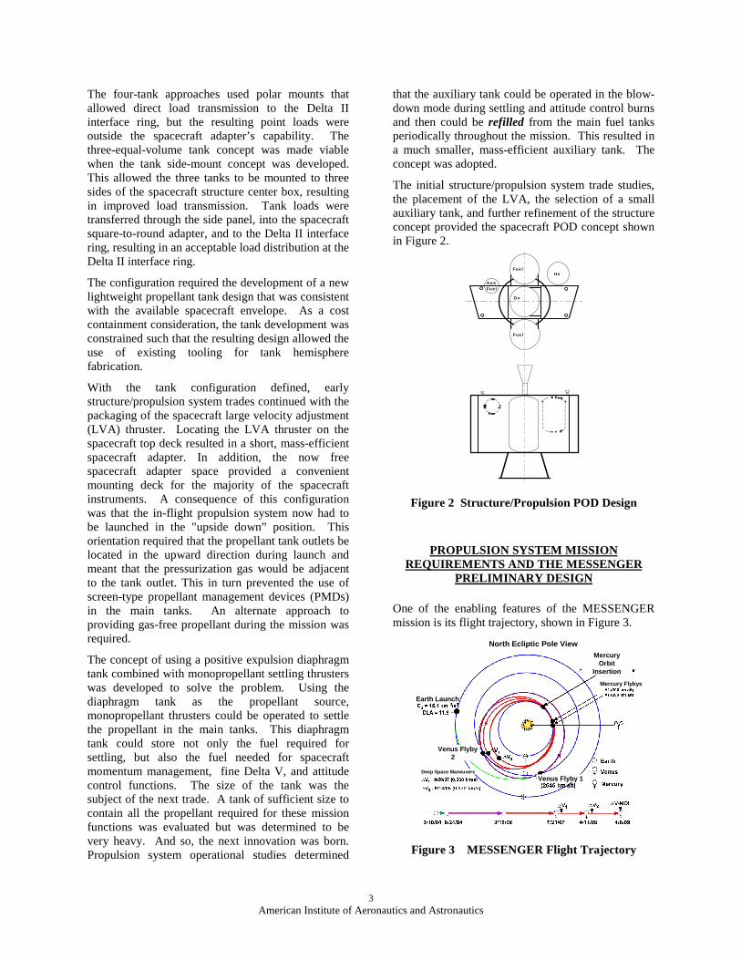
that the auxiliary tank could be operated in the blow-down mode during settling and attitude control burns and then could be refilled from the main fuel tanks periodically throughout the mission. This resulted in a much smaller, mass-efficient auxiliary tank. The concept was adopted.
The initial structure/propulsion system trade studies, the placement of the LVA, the selection of a small auxiliary tank, and further refinement of the structure concept provided the spacecraft POD concept shown in Figure 2.
Figure 2 Structure/Propulsion POD Design
PROPULSION SYSTEM MISSION REQUIREMENTS AND THE MESSENGER
PRELIMINARY DESIGN
One of the enabling features of the MESSENGER mission is its flight trajectory, shown in Figure 3.
Figure 3 MESSENGER Flight Trajectory
North Ecliptic Pole ViewMercury
OrbitInsertion
Mercury Flybys
Earth Launch
Venus Flyby2
Venus Flyby 1Deep Space Maneuvers
HeFue l
O x
Fue l
Fue lA u x

4American Institute of Aeronautics and Astronautics
While this innovative flight plan significantly reduces the launch vehicle C3 requirements and the total spacecraft Delta V requirements, it increases the total flight time and necessitates a number of mid-course corrections and post Mercury Orbit Insertion (MOI) maneuvers. Mission designers produced the detailed propulsion maneuver requirements outlined in Table 1. Note that in Table 1, highlighted events are conducted using the bipropellant LVA thruster while all other events are conducted using the monopropellant thrusters. The LVA thruster is used a minimum of six times throughout the mission. For a dual-mode propulsion system, this directly affects the propulsion system fuel and oxidizer system pressurization scheme and its ability to limit the diffusion of nitrogen tetroxide (N2O4 or NTO). NTO diffusion is a design consideration for long-duration missions. NTO vapor migration, resulting in NTO accumulation in the fuel pressurization system, could result in energetic reaction and hardware failure. The MESSENGER propulsion system configuration had to address this potential occurrence.
Four pressurization schemes were traded, as shown in Figure 4. These included single helium tank pressurization (based on the Near Earth Asteroid Rendezvous (NEAR) spacecraft), separate fuel and oxidizer helium tanks, pyro ladder oxidizer tank isolation, and single tank/dual circuit pressurization concepts. The figures of merit were based on acceptable NTO diffusion prevention, mass efficiency, packaging capability, and operational flexibility.
The single helium tank concept, while efficient from a mass and packaging standpoint, did not provide adequate NTO diffusion protection since the fuel and oxidizer tanks shared the same pressurization path.
Table 1 Propulsion System Propulsive Maneuver Requirements
Date Event ∆V(m/s)
3/10/04 DELTA Despin 03/10/04 Separate From DELTA 03/20/04 Injection Correction 11.096/10/04 #1 Venus Swingby Nav 2.856/22/04 Extra Nav Burn 0.163/2/06 #2 Venus Swingby Nav 2.97
3/14/06 Extra Nav Burn 6.267/11/07 #1 Mercury Swingby Nav 6.319/19/07 DSM 1 37.2210/3/07 DSM 1 Cleanup 0.544/1/08 Mercury #2 Swingby Nav 6.18
6/12/08 DSM 2 275.228/7/08 DSM 2 Cleanup 17.668/7/08 DSM 2 Cleanup - Sunward 1.94
3/22/09 Mercury Orbit Insertion Nav 4.554/5/09 MOI 1589.964/8/09 MOI Cleanup 35.94
7/3-12/28/09 3 Periapse Lower Maneuv. 75.187/4-12/29/09 3 Orbit Period Adjust Maneuv. 11.69
4/5/10 N2H4 Nav ∆V Reserve 121.114/5/10 N2H4 ∆V Reserve 43.174/5/10 Biprop ∆V Reserve 50
TOTAL 2300
Figure 4 Pressurization System Trades.
Ox
Fu Fu
GHeTank
GHeTank
Ox
NO NC
NO NC
NO NC
NO NC
Fu Fu
Baseline System
Pyro Ladder
Separate PressurizationMultiple He Tanks
GHeTank
Ox
Fu Fu
GHeTank
GHeTank
GHeTank
Ox
Fu Fu
Separate Pressurization
Single He Tanks
5American Institute of Aeronautics and Astronautics
Both the separate helium tanks and pyro-ladder isolation concepts provided excellent NTO diffusion prevention but were either heavy, required more packaging volume, or limited operational flexibility. Again, another innovation was required. The MESSENGER solution was the use of a single helium tank with dedicated fuel and oxidizer outlets. This configuration made use of the helium tank as an NTO barrier. In addition, two isolation valves were added to provide pressurization system cross-strapping capability in the event of a high-pressure latch valve or regulator failure. This provided additional system redundancy for very little mass.
The final set of system trades focused on the thruster selection. Two bipropellant thrusters were evaluated for use as the LVA thruster. The higher performing, lower thrust Leros-1c was traded against the lower performing, higher thrust Leros-1b. The model with the higher thrust traded more favorably when gravity losses during the MOI burn were considered, and the Leros-1b was selected. In addition, the Leros-1b had a larger and more thermally tolerant operating box. Settling thrusters were also traded. Dedicated small 4.4-N settling thrusters were traded against using the existing 22-N LVA thrust vector control (LVA-TVC) thrusters. While the smaller settling thrusters were more mass efficient, a combination of cost and limited packaging space ruled out their use.
MISSION ENABLING LOW MASS PROPELLANT TANK DEVELOPMENT
As discovered during the earlier system trades, development of a low-mass, side-mounted tank was key to meeting the spacecraft mass requirements. Early in the MESSENGER program, a joint JHU/APL, Aerojet and Pressure Systems Incorporated (PSI) tank development program was initiated. Preliminary tank requirements outlined in Table 2 provided the starting point.
Table 2 Main Propellant Tank Preliminary Requirements
Requirement ValueTank Volume 200 Liters (12,200 in3)
Tooling Existing
Mounting Side
Tank Structural Load Sharing None
Nutation Control Features Delta II Users Manual
Tank Design EWR 127-1, Oct 1997
The planned spacecraft test approach surfaced another design consideration. The test approach included a spacecraft-level proto-flight sine vibration test. To allow decoupling of the tank and spacecraft structure primary modes during this test, a minimum
fundamental frequency goal of 85 Hz was levied on the propellant tank as an additional design consideration.
Tank trades began with determining the required side-mounting scheme. Over 50 concepts were evaluated using simplified finite element models to assess tank mass and fundamental frequency trends. The minimum fundamental frequency goal of 85 Hz was found not to be achievable without transmitting structure loads to the tank. The spacecraft proto-flight sine test approach was thus modified to eliminate the full sine test at the spacecraft level and to perform proto-flight testing at the piece part and subassembly levels. The tank concept selected had an estimated 50-Hz fundamental frequency and a calculated mass of 9.5 kg (20.9 lb).
In parallel to the concept study, analytically-based nutation control assessments were made using the preliminary tank configuration and propellant load. The 559-mm (22-inch) diameter, 200-liter (12200-in3) tank was required to be compliant with the Delta II nutation requirements at the planned propellant load range. Nutation is caused by the presence of energy sinks in a stack spinning about its minor moment of inertia. Propellant movement in the MESSENGER tanks creates energy sinks, and the Delta II 3rd Stage/MESSENGER spacecraft stack spins about its minor moment of inertia. The study concluded that nutation control features (baffles) were likely required within the propellant tanks and that sub-scale drop tests should be performed to determine empirically the configuration of those features. The propellant tank design activity was stopped until the baffle configuration was defined.
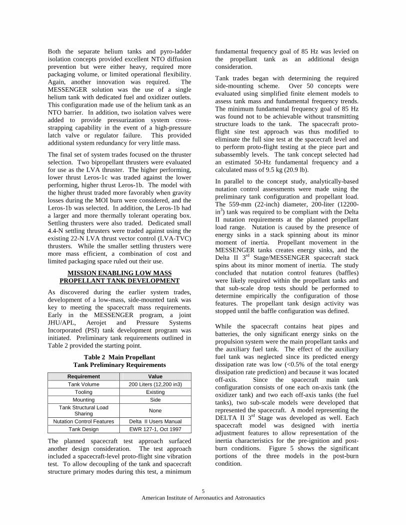
While the spacecraft contains heat pipes and batteries, the only significant energy sinks on the propulsion system were the main propellant tanks and the auxiliary fuel tank. The effect of the auxiliary fuel tank was neglected since its predicted energy dissipation rate was low (<0.5% of the total energy dissipation rate prediction) and because it was located off-axis. Since the spacecraft main tank configuration consists of one each on-axis tank (the oxidizer tank) and two each off-axis tanks (the fuel tanks), two sub-scale models were developed that represented the spacecraft. A model representing the DELTA II 3rd Stage was developed as well. Each spacecraft model was designed with inertia adjustment features to allow representation of the inertia characteristics for the pre-ignition and post-burn conditions. Figure 5 shows the significant portions of the three models in the post-burn condition.
6American Institute of Aeronautics and Astronautics
Figure 5 Main Propellant Tank Sub-scale Models
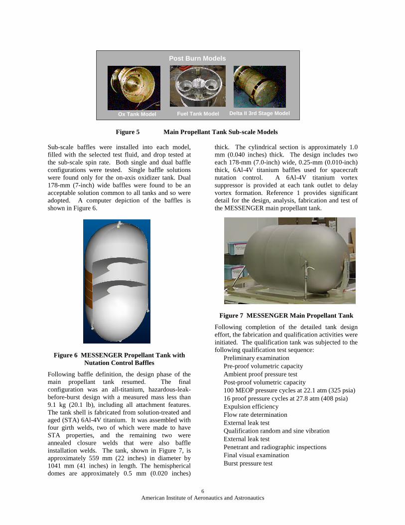
Sub-scale baffles were installed into each model, filled with the selected test fluid, and drop tested at the sub-scale spin rate. Both single and dual baffle configurations were tested. Single baffle solutions were found only for the on-axis oxidizer tank. Dual 178-mm (7-inch) wide baffles were found to be an acceptable solution common to all tanks and so were adopted. A computer depiction of the baffles is shown in Figure 6.
Figure 6 MESSENGER Propellant Tank with Nutation Control Baffles
Following baffle definition, the design phase of the main propellant tank resumed. The final configuration was an all-titanium, hazardous-leak-before-burst design with a measured mass less than 9.1 kg (20.1 lb), including all attachment features. The tank shell is fabricated from solution-treated and aged (STA) 6Al-4V titanium. It was assembled with four girth welds, two of which were made to have STA properties, and the remaining two were annealed closure welds that were also baffle installation welds. The tank, shown in Figure 7, is approximately 559 mm (22 inches) in diameter by 1041 mm (41 inches) in length. The hemispherical domes are approximately 0.5 mm (0.020 inches)
thick. The cylindrical section is approximately 1.0 mm (0.040 inches) thick. The design includes two each 178-mm (7.0-inch) wide, 0.25-mm (0.010-inch) thick, 6Al-4V titanium baffles used for spacecraft nutation control. A 6Al-4V titanium vortex suppressor is provided at each tank outlet to delay vortex formation. Reference 1 provides significant detail for the design, analysis, fabrication and test of the MESSENGER main propellant tank.
Figure 7 MESSENGER Main Propellant Tank
Following completion of the detailed tank design effort, the fabrication and qualification activities were initiated. The qualification tank was subjected to the following qualification test sequence:• Preliminary examination• Pre-proof volumetric capacity• Ambient proof pressure test• Post-proof volumetric capacity• 100 MEOP pressure cycles at 22.1 atm (325 psia)• 16 proof pressure cycles at 27.8 atm (408 psia)• Expulsion efficiency• Flow rate determination • External leak test• Qualification random and sine vibration• External leak test• Penetrant and radiographic inspections• Final visual examination• Burst pressure test
Fuel Tank ModelOx Tank Model Delta II 3rd Stage Model
Post Burn Models
7American Institute of Aeronautics and Astronautics
The vibration tests were performed with deionized water. Although a test fluid having the same specific gravity (s.g.) as N2O4 (s.g. ~1.44) would be optimal for testing purposes, no test fluid could be found that matched the s.g. and also had existing fracture-related data. Having fracture data is not generally required for a consumable qualification unit, but since the overall MESSENGER test approach was to perform flight tank proto-flight sine vibration testing consistent with the qualification test approach, the decision was made to test with an alternate test fluid. Deionized water was selected. The required vibration levels were adjusted to account for the fluid density difference.
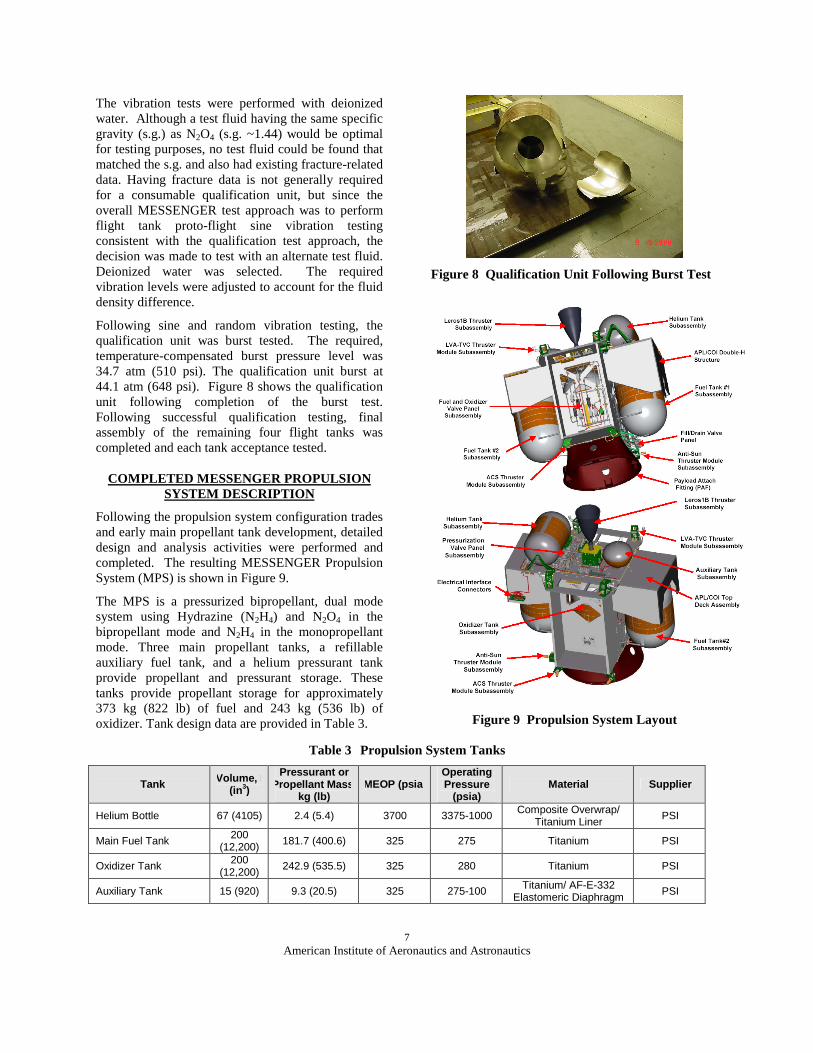
Following sine and random vibration testing, the qualification unit was burst tested. The required, temperature-compensated burst pressure level was 34.7 atm (510 psi). The qualification unit burst at 44.1 atm (648 psi). Figure 8 shows the qualification unit following completion of the burst test. Following successful qualification testing, final assembly of the remaining four flight tanks was completed and each tank acceptance tested.
COMPLETED MESSENGER PROPULSION SYSTEM DESCRIPTION
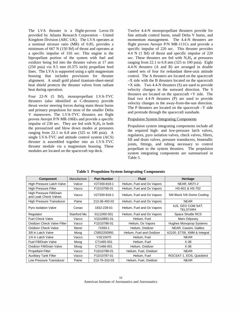
Following the propulsion system configuration trades and early main propellant tank development, detailed design and analysis activities were performed and completed. The resulting MESSENGER Propulsion System (MPS) is shown in Figure 9.
The MPS is a pressurized bipropellant, dual mode system using Hydrazine (N2H4) and N2O4 in the bipropellant mode and N2H4 in the monopropellant mode. Three main propellant tanks, a refillable auxiliary fuel tank, and a helium pressurant tank provide propellant and pressurant storage. These tanks provide propellant storage for approximately 373 kg (822 lb) of fuel and 243 kg (536 lb) of oxidizer. Tank design data are provided in Table 3.
Figure 8 Qualification Unit Following Burst Test
Figure 9 Propulsion System Layout
Table 3 Propulsion System Tanks
Tank Volume, l (in3)
Pressurant or Propellant Mass,
kg (lb)MEOP (psia)
Operating Pressure
(psia)Material Supplier
Helium Bottle 67 (4105) 2.4 (5.4) 3700 3375-1000 Composite Overwrap/ Titanium Liner
PSI
Main Fuel Tank 200 (12,200) 181.7 (400.6) 325 275 Titanium PSI
Oxidizer Tank 200 (12,200)
242.9 (535.5) 325 280 Titanium PSI
Auxiliary Tank 15 (920) 9.3 (20.5) 325 275-100 Titanium/ AF-E-332 Elastomeric Diaphragm PSI

8American Institute of Aeronautics and Astronautics
The required spacecraft velocity changes, attitude control, thrust vector control, and momentum management functions are accomplished with a total of 17 thrusters. Propellant and pressurant control is provided by existing off-the-shelf integrating components. A thermal management system consisting of heaters and thermostats maintains the system temperature within the required range. A dual-string electrical system interfaces the MPS to the spacecraft power and control systems
The MPS hydraulic schematic, shown in Figure 10, consists of four main elements: the pressurization system, fuel feed system, oxidizer feed system, and thruster modules. Additional MPS constituents include secondary structures, electrical subsystem, and the thermal management subsystems.
The pressurant system includes the helium tank, high-pressure latch valves, regulators, cross-strapping pyro valves, check valves, low-pressure latch valve, fill and drain valves, filters, and pressure transducers. Helium, pressurized to approximately 3375 psia, is contained using a triple seal fill and drain valve and high-pressure latch valves. When the fuel-side pressurization system is activated, helium flows
down the fuel leg, through a 5-µm filter, high-pressure latch valve, series redundant regulators, and two sets of parallel redundant check valves prior to entering the two main fuel tanks. When the oxidizer-side pressurization system is activated, helium flows down the oxidizer leg, through a 5-µm filter, high-pressure latch valve, series redundant regulator, filter, set of parallel redundant check valves, and low-pressure latch valve prior to entering the oxidizer tank. Cross strapping pyro valves are included both upstream and downstream of the fuel and oxidizer regulators. These pyro valves are risk-mitigation features and are in place to provide pressurization system cross strapping capability in the event of a high-pressure latch valve or regulator failure.
The fuel supply system includes two main fuel tanks, a diaphragm auxiliary fuel tank, tank outlet latch valves, fill and drain valves, filters, and pressure transducers. The three fuel tanks are connected to a common manifold that feeds the thrusters. To initiate use of the fuel system, the auxiliary tank outlet bleed valve is opened to fill the fuel manifold slowly, mitigating water hammer and adiabatic detonation concerns.
Figure 10 Propulsion System Hydraulic Schematic
MESSENGERPropulsion
SystemSchematic
Fuel Tank
#1
PFT1
TFT1A
FT1HSV
FT1PSVFT1F
PAUX A
Tank
HPLVF HPLVO
OHPFFHPF
OxidizerTank
POREGPFREG
PFT2
TLVAV
POT
TLVAF
TFT2ATOTB
OTLV
LVAF
HPPV
LPPV
FREG OREG
HFTP HOTP
OCKV1
OTHSV
OTPSV
OTF
FT2PSV
FT2F
S
GHe
Auxiliary FuelTank
PGHE
PAUX B
TGHEC2
TAUX A
TAUX B
AFTLV1
HeSV
FT2HSV
15µ AFTF
AFTPSV
AFTHSV
AFTLV2
5µ 5µ
TBD µ TBD µ
10 µ
S
FT2CKV10 µFT1CKV
10 µ
40µ
Fuel Tank
#2
40µ
15µ 15µ
35µ35µ
40µ
40µ
15µ
sc
dcdc
dc dcFTLV2
40µdc
FTLV1
40µdcdc
sc
FCKTP
sc40µ 40µ
FCKV 10 µ
OCKV2
TemperatureSensor
Service Valve
Filter
PyrotechnicIsolation Valve
Dual SeriesRegulator withIntegral Filter
sc
dc
S
PressureTransducer
Dual ParallelCheck ValvewithIntegral Filter
StererCheckValve
Dual CoilLatch Valvewith IntegralFilter
Single CoilLatch Valvewith IntegralFilter
Mono-PropellantThruster withIntegral Filter
Bi-PropellantThruster withIntegral FilterKEY
S2
20µ
A4
20µ
B4
20µ
B3
20µ
A3
A2
20µ
S1
20µ
C2C1
B120µ
C3B2
20µ
C4
A1
20µ
TFT2A
TFT2T
TFT1A
TFT1T
TOTT
TOTA
TGHETCTGHEC1
TGHEU
Module CA2
Module CA1
Module CB3
Module CB4
25µ
25µ
25µ
25µ
OPIF
PFF
TS1V
TB4V
TC2V
TB1V
20µ
TAUX T
40 µ
OPILVdc
P1
20µTP1V
P220µTP2V
TP1C
TP2C

9American Institute of Aeronautics and Astronautics
The remaining auxiliary tank latch valve is opened for all thruster and refill operations. If access to the main fuel tanks is required, the latch valve associated with the selected source tank is opened. An additional fuel latch valve located upstream of the LVA thruster is opened when LVA thruster operation is required.
The oxidizer system includes the main oxidizer tank, an outlet latch valve, fill and drain valves, a filter, and a pressure transducer. When using the system in the bipropellant mode, oxidizer flows out of the tank through the tank filter and latch valve to the LVA thruster valve.
MPS Propellant and Pressurant Tanks
The helium tank is a titanium-lined composite over-wrapped leak-before-burst pressure vessel (COPV) based on the flight-proven A2100 helium tank. A second outlet was added to the existing helium tank to provide a dual pressurization capability for the fuel and oxidizer systems. The helium tank is supported by two brackets - an aluminum fixed bracket and a magnesium floating bracket. The fixed bracket is machined from 7075-T73 aluminum and is secured to the helium tank using a jam nut. The fixed bracket secures the helium in all three axes and rotations. The floating bracket is machined from ZK60A-T5 magnesium and includes a mono-ball bearing that allows for tank axial growth and slight rotations. Both the fixed and floating brackets are secured to the spacecraft composite structure using a total of ten #10 A286 fasteners.
The main propellant tanks are symmetrically positioned about the spacecraft's centerline to maintain mass control during propellant expulsion in flight. Two fuel tanks flank the center oxidizer tank. Each tank’s main load path is through a Custom 455 steel bearing pin that interfaces to a titanium receiver fitting in the composite center box structure. The four titanium struts, two each boss mounted and two each side mounted, provide for tank lateral support.
A small 6Al-4V titanium auxiliary tank is a hazardous-leak-before-burst design. It has an internal diaphragm to allow positive expulsion of propellant for use in attitude control, fine Delta V, and settling burns. The auxiliary tank has an internal volume of 15.1 liters (920 in3). The auxiliary tank is flange mounted to the composite structure top deck. The tank operates in blow down mode between 280 and 110 psia and is recharged in flight. The auxiliary tank is flight proven and has flown on numerous missions including the Defense Meteorological Satellite Program (DMSP), Television and Infrared
Observation Satellite (TRIOS), Miniature Sensor Technology Integration Program (MSTI), Small Spacecraft Technology Initiative Program (SSTI), and Television Infrared Observation Satellite (TIROS).
MPS Thrusters
The MPS includes a total of 17 thrusters. Three thruster types, arranged in five different thruster module configurations, provide the required spacecraft forces. The MPS thruster arrangement is shown in Figure 11. Table 4 describes the thruster modules and identifies the thrusters contained within each.
+X
+Z
+Y
B2B1
A4A3
A2A1
C4
C3
C2
C1
S2
S1
B4B3
P2
P1
LVA
Figure 11 MPS Thruster Arrangement
Table 4 MPS Thruster Module Definition
Module Type Module Name ThrustersLVA LVA LVA (660 N)
LVA-TVC CA1C1 (22 N) A1 (4.4 N)
LVA-TVC CA2C2 (22 N)A2 (4.4 N)
LVA-TVC CB3C3 (22 N) B1 (4.4 N)
LVA-TVC CB4C4 (22 N) B2 (4.4 N)
ACS A3 A3 (4.4 N)
ACS A4 A4 (4.4 N)
ACS B3 B3 (4.4 N)
ACS B4 B4 (4.4 N)
Anti-Sun S1 S1 (4.4 N)
Anti-Sun S2 S2 (4.4 N)
Pro-Sun P1 P1 (4.4 N)
Pro-Sun P2 P2 (4.4 N)
10American Institute of Aeronautics and Astronautics
The LVA thruster is a flight-proven Leros-1b provided by Atlanta Research Corporation – United Kingdom Division (ARC UK). The LVA operates at a nominal mixture ratio (MR) of 0.85, provides a minimum of 667 N (150 lbf) of thrust and operates at a specific impulse of 316 sec. This engine is the bipropellant portion of the system with fuel and oxidizer being fed into the thruster valves at 17 atm (250 psia) via 9.5 mm (0.375 inch) propellant feed lines. The LVA is supported using a split magnesium housing that includes provisions for thruster alignment. A small gold plated titanium-sheet-metal heat shield protects the thruster valves from radiant heat during operation.
Four 22-N (5 lbf), monopropellant LVA-TVC thrusters (also identified as C-thrusters) provide thrust vector steering forces during main thrust burns and primary propulsion for most of the smaller Delta V maneuvers. The LVA-TVC thrusters are flight proven Aerojet P/N MR-106Es and provide a specific impulse of 230 sec. They are fed with N2H4 in both the pressurized and blow down modes at pressures ranging from 22.1 to 6.8 atm (325 to 100 psia). A single LVA-TVC and attitude control system (ACS) thruster is assembled together into an LVA-TVC thruster module via a magnesium housing. These modules are located on the spacecraft top deck.
Twelve 4.4-N monopropellant thrusters provide for fine attitude control burns, small Delta V burns, and momentum management. The 4.4-N thrusters are flight proven Aerojet P/N MR-111Cs and provide a specific impulse of 220 sec. This thruster provides 4.4 N (1 lbf) of thrust and specific impulse of 220 sec. These thrusters are fed with N2H4 at pressures ranging from 22.1 to 6.8 atm (325 to 100 psia). Eight 4.4-N thrusters (A and B) are arranged in double canted sets of four for redundant three-axis attitude control. The A thrusters are located on the spacecraft –X side with the B thrusters located on the spacecraft +X side. Two 4.4-N thrusters (S) are used to provide velocity changes in the sunward direction. The S thrusters are located on the spacecraft +Y side. The final two 4.4-N thrusters (P) are used to provide velocity changes in the away-from-the-sun direction. The P thrusters are located on the spacecraft –Y side and protrude through the spacecraft sunshade.
Propulsion System Integrating Components
Propulsion system integrating components include all the required high- and low-pressure latch valves, regulators, pyro isolation valves, check valves, filters, fill and drain valves, pressure transducers, bimetallic joints, fittings, and tubing necessary to control propellant to the system thrusters. The propulsion system integrating components are summarized in Table 5.
Table 5 Propulsion System Integrating Components
Component Manufacturer Part Number Fluid Heritage
High Pressure Latch Valve Valcor V27200-818-1 Helium, Fuel and Ox Vapors NEAR, MSTI-2
High Pressure Filter Vacco F1D10785-01 Helium, Fuel and Ox Vapors HS-601 & HS-702
High Pressure Fill/Drain and Leak Check Valves Vacco V27200-818-1 Helium, Fuel and Ox Vapors SM Block IVb Dome Cooling
High Pressure Transducer Paine 213-36-450-02 Helium, Fuel and Ox Vapors NEAR
Pyro Isolation Valve Conax 1832-228-01 Helium, Fuel and Ox VaporsIUS, GEO COM SAT,
TELSTAR4
Regulator Stanford Mu 0111000-501 Helium, Fuel and Ox Vapors Space Shuttle RCS
Fuel Check Valve Vacco V1D10891-01 Helium, Fuel Mars Odyssey
Oxidizer Check Valve Filter Vacco F1D10786-01 Helium, Ox Vapors Hughes Monoprop Systems
Oxidizer Check Valve Sterer 71593-1 Helium, Oxidizer NEAR, Cassini, Galileo
3/8 in Latch Valve Moog C5852200991 Helium, Fuel and Oxidizer A2100, ETS8, XMM & Integral
1/4 in Latch Valve Vacco V1E10470 Helium, Fuel NEAR
Fuel Fill/Drain Valve Moog C71465-001 Helium, Fuel X-38
Oxidizer Fill/Drain Valve Moog C71466-001 Helium, Oxidizer X-38
Propellant Filter Vacco F1D10788-01 Helium, Fuel, Oxidizer NEAR
Auxiliary Tank Filter Vacco F1D10787-01 Helium, Fuel ROCSAT-1, EOS, Quickbird
Low Pressure Transducer Paine 213-76-310-03 Helium, Fuel, Oxidizer NEAR

11American Institute of Aeronautics and Astronautics
Secondary Structures
The MPS includes secondary structures/ brackets to support thrusters, fill and drain valves, and electrical interface connectors. Propulsion system secondary structures are identified in Table 6.
Table 6 MPS Secondary Structures
Bracket Material
Helium Tank Fixed Bracket 7075-T73 Aluminum
Helium Tank Floating Bracket ZK60A-T5 Magnesium
LVA Thruster Housing ZK60A-T5 Magnesium
LVA-TVC Thruster Housing ZK60A-T5 Magnesium
ACS Thruster Bracket ZK60A-T5 Magnesium
Anti-Sun Thruster Bracket ZK60A-T5 Magnesium
Pro-Sun Thruster Bracket ZK60A-T5 Magnesium
Fill/Drain Valve Bracket ZK60A-T5 Magnesium
Leak Check Bracket ZK60A-T5 Magnesium
Electrical Connector Bracket ZK60A-T5 Magnesium
MPS Electrical Subsystem
The MPS includes a dual string electrical system with harnesses, diode terminal boards, and connectors that are used to control individual propulsion elements. The MPS electrical interface is provided in Table 7.
MPS Thermal Subsystem
The MPS thermal system employs heaters to maintain acceptable system temperatures. Heaters are used during the cruise phase to maintain propellant temperatures and in the operational phases to pre-heat thrusters in preparation for operation. Propulsion system heater power is outlined in Table 8. Cruise-phase heaters are installed on the propellant and pressurant tanks, thruster valves, valve panel, fill and drain valve bracket, and various propellant manifolds. Cruise-phase heaters are controlled by spacecraft software (helium and main
propellant tanks) and with mechanical thermostats (all remaining cruise-phase heaters).
Operational phase heaters include monopropellant thruster catalyst bed heaters and the LVA flange heater. All catalyst bed heaters are time controlled while, when enabled, the LVA flange heater is controlled with mechanical thermostats.
Table 7 MPS Electrical Interface
Interface Electrical Function
PMX-J1 Primary Instrumentation
PMX-J2 Secondary Instrumentation
PMX-J3 Primary Fuel Tank Latch Valves, A and B Thrusters
PMX-J4 Secondary Fuel Tank Latch Valves, A and B Thrusters
PMX-J5 Primary Helium and Ox Tank and LVA Latch Valves, LVA, C, S and P Thrusters
PMX-J6 Secondary Helium and Ox Tank and LVA Latch Valves, LVA, C, S and P Thrusters
PMX-J7 HPPV and LPPL Primary Initiators
PMX-J8 HPPV and LPPL Secondary Initiators
PMX-J9 MPS Test Connector
PMX-J10 MPS Umbilical Connector
PMX-J11 Primary Instrumentation and Heater Power
PMX-J12 Secondary Instrumentation and Heater Power
PROPULSION SYSTEM OPERATION
MPS operational definition was initiated early in the program to allow time for design modifications and to define test requirements for the MPS hydraulic test discussed in the next section. This section discusses the primary MPS operational modes.
Table 8 MPS Heater Power
Heater Quantity Primary Control Secondary Control Power Total, Watts
Main Propellant Tank 3 Spacecraft Thermostat 61.6
Auxiliary Tank 1 Thermostat Thermostat 6.2
Helium Tank 1 Spacecraft Thermostat 10.1
Valve and Lines 31 Thermostat Thermostat 65.1
LVA Flange 1 Thermostat Thermostat 19
C Catbed Heaters 4 Time Time 17.1
ABS Catbed Heaters 10 Time Time 27.4
P Catbed Heaters 2 Time Time 5.6
12American Institute of Aeronautics and Astronautics
MPS operation is divided into a Launch Mode, an Idle Mode, and three active operational modes. A unique element of MPS active operation is the periodic refill of the positive-expulsion diaphragm auxiliary tank from the two main fuel tanks. This innovative operational approach was adopted to allow utilization of a small low-mass auxiliary tank. The modes are described below.
Launch Mode: Launch mode begins one hour prior to launch with temperature conditioning of the main propellant tanks, transitions to launch and spacecraft separation, continues through fuel-feed manifold evacuation and bleed-in in preparation for first thruster operation, and ends with spacecraft de-tumble.
Idle Mode: The MPS is in idle mode when the propulsion system is disabled and no preparation for operation is in process. The idle phase begins immediately following the launch phase and spacecraft de-tumble. Idle Mode is the predominant mode during the long journey to Mercury.
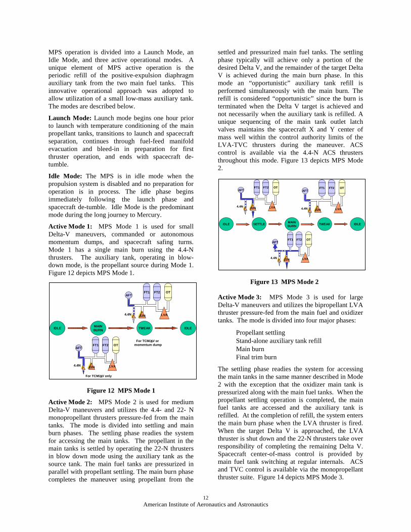
Active Mode 1: MPS Mode 1 is used for small Delta-V maneuvers, commanded or autonomous momentum dumps, and spacecraft safing turns. Mode 1 has a single main burn using the 4.4-N thrusters. The auxiliary tank, operating in blow-down mode, is the propellant source during Mode 1. Figure 12 depicts MPS Mode 1.
Figure 12 MPS Mode 1
Active Mode 2: MPS Mode 2 is used for medium Delta-V maneuvers and utilizes the 4.4- and 22- N monopropellant thrusters pressure-fed from the main tanks. The mode is divided into settling and main burn phases. The settling phase readies the system for accessing the main tanks. The propellant in the main tanks is settled by operating the 22-N thrusters in blow down mode using the auxiliary tank as the source tank. The main fuel tanks are pressurized in parallel with propellant settling. The main burn phase completes the maneuver using propellant from the
settled and pressurized main fuel tanks. The settling phase typically will achieve only a portion of the desired Delta V, and the remainder of the target Delta V is achieved during the main burn phase. In this mode an “opportunistic” auxiliary tank refill is performed simultaneously with the main burn. The refill is considered “opportunistic” since the burn is terminated when the Delta V target is achieved and not necessarily when the auxiliary tank is refilled. A unique sequencing of the main tank outlet latch valves maintains the spacecraft X and Y center of mass well within the control authority limits of the LVA-TVC thrusters during the maneuver. ACS control is available via the 4.4-N ACS thrusters throughout this mode. Figure 13 depicts MPS Mode 2.
Figure 13 MPS Mode 2
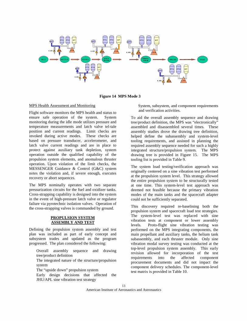
Active Mode 3: MPS Mode 3 is used for large Delta-V maneuvers and utilizes the bipropellant LVA thruster pressure-fed from the main fuel and oxidizer tanks. The mode is divided into four major phases:
• Propellant settling• Stand-alone auxiliary tank refill• Main burn• Final trim burn
The settling phase readies the system for accessing the main tanks in the same manner described in Mode 2 with the exception that the oxidizer main tank is pressurized along with the main fuel tanks. When the propellant settling operation is completed, the main fuel tanks are accessed and the auxiliary tank is refilled. At the completion of refill, the system enters the main burn phase when the LVA thruster is fired. When the target Delta V is approached, the LVA thruster is shut down and the 22-N thrusters take over responsibility of completing the remaining Delta V. Spacecraft center-of-mass control is provided by main fuel tank switching at regular internals. ACS and TVC control is available via the monopropellant thruster suite. Figure 14 depicts MPS Mode 3.
IDLE MAINBURN
TWEAK IDLE
FT1 OTFT2AFT
LVA22N4.4N
FT1 OTFT2AFT
LVA22N4.4N
For TCM/∆∆∆∆V only
For TCM/∆∆∆∆V or momentum dump
IDLE SETTLEMAINBURN
TWEAK IDLE
FT1 OTFT2AFT
LVA22N4.4N
FT1 OTFT2AFT
LVA22N4.4N
FT1 OTFT2AFT
LVA22N4.4N
13American Institute of Aeronautics and Astronautics
Figure 14 MPS Mode 3
MPS Health Assessment and Monitoring
Flight software monitors the MPS health and status to ensure safe operation of the system. System monitoring during the idle mode utilizes pressure and temperature measurements and latch valve tel-tale position and current readings. Limit checks are invoked during active modes. These checks are based on pressure transducer, accelerometer, and latch valve current readings and are in place to protect against auxiliary tank depletion, system operation outside the qualified capability of the propulsion system elements, and anomalous thruster operation. Upon violation of the limit checks, the MESSENGER Guidance & Control (G&C) system notes the violation and, if severe enough, executes recovery or abort sequences.
The MPS nominally operates with two separate pressurization circuits for the fuel and oxidizer tanks. Cross-strapping capability is designed into the system in the event of high-pressure latch valve or regulator failure via pyrotechnic isolation valves. Operation of the cross-strapping valves is commanded by ground.
PROPULSION SYSTEM ASSEMBLY AND TEST
Defining the propulsion system assembly and test plan was included as part of early concept and subsystem trades and updated as the program progressed. The plan considered the following:
• Overall assembly sequence and drawing tree/product definition
• The integrated nature of the structure/propulsion system
• The “upside down” propulsion system• Early design decisions that affected the
JHU/APL sine vibration test strategy
• System, subsystem, and component requirements and verification activities.
To aid the overall assembly sequence and drawing tree/product definition, the MPS was “electronically” assembled and disassembled several times. These assembly studies drove the drawing tree definition, helped define the subassembly and system-level tooling requirements, and assisted in planning the required assembly sequence needed for such a highly integrated structure/propulsion system. The MPS drawing tree is provided in Figure 15. The MPS tooling list is provided in Table 9.
The system load testing/verification approach was originally centered on a sine vibration test performed at the propulsion system level. This strategy allowed the entire propulsion system to be structurally tested at one time. This system-level test approach was deemed not feasible because the primary vibration modes of the main tanks and the spacecraft adapter could not be sufficiently separated.
This discovery required re-baselining both the propulsion system and spacecraft load test strategies. The system-level test was replaced with sine vibration tests at component or lower assembly levels. Proto-flight sine vibration testing was performed on the MPS integrating components, the main propellant and auxiliary tanks, the helium tank subassembly, and each thruster module. Only sine vibration modal survey testing was conducted at the top-level propulsion system assembly. This early revision allowed for incorporation of the test requirements into the affected component procurement documents and did not impact the component delivery schedules. The component-level test matrix is provided in Table 10.
F T 1 O TF T 2A F T
L V A2 2 N4 .4 N
T W E A K ID L EF IN A LT R IM
F T 1 O TF T 2A F T
L V A2 2 N4 .4 N
F T 1 O TF T 2A F T
L V A2 2N4 .4 N
F T 1 O TF T 2A F T
L V A2 2 N4 .4 N
ID L E S E T T L EM A INB U R NR E F IL L
F T 1 O TF T 2A F T
L V A2 2 N4 .4N

14American Institute of Aeronautics and Astronautics
Figure 15 MPS Drawing Tree
Table 9 MPS Tooling List
Tool Function
Tank Valve Panel
Supports Tank During Propellant Tank Subassembly Fabrication
Top Deck Weld Plate
Fabricate and Proof/Leak Test the Pressurant Panel, LVA-TVC and Anti-Sun Thruster Modules, LVA Thruster Module and Top Deck Thruster Module Assembly
Valve Panel Weld Plate
Fabricate and Proof/Leak Test the Propellant Valve Panel
Fuel Check Valve Weld
Plate
Used to Fabricate and Proof/Leak Test the Fuel Check Valve Panel and Fill/Drain Manifolds
Bottom Deck Weld
Plate
Fabricate and Proof/Leak the ACS and Anti-Sun Thruster Modules and Bottom Deck Thruster Module Assembly
Assembly/
Rotation Fixture
Supports Propulsion System During Assembly and Allows 360° of Rotation About the Spin Axis and Lateral Axis. Supports System in the Upside Down Position During System Hydraulic Testing
Valve Saver Panel
Allows Connection to the MPS Using Facility Type Valves and Filters
EGSE Provides Power, Command and Control of the MPS via Eight Separate Graphical User Interfaces (GUIs)
Hydraulic/
Pneumatic Cart
Provides Control of Gases and Fluid to be Introduced to the Propulsion System
Protective Covers
Non-Flight Protective Covers for the Thruster Modules and Tanks
Table 10 MPS Component Test Matrix
Component or subassembly
Fu
nct
ion
al
Tes
tin
g
Pro
of
Tes
tin
g
Lea
k T
esti
ng
Ran
do
m
vib
rati
on
Sin
e V
ibra
tio
n
High Pres. Fill/Drain Valves √ √ √High Pressure Latch Valve √ √ √ √High Pressure Filter √ √ √Regulators √ √ √ √Pyro Valves √ √ √ √Pressure Transducers √ √ √ √Oxidizer Check Valves √ √ √ √Fuel Check Valves √ √ √ √Moog 3/8 in Latch Valves √ √ √ √Vacco ¼ in. Latch Valves √ √ √ √Propellant Filters √ √ √Propellant Fill/Drain Valves √ √ √BiPropellant Thruster √ √ √ √ √Monopropellant Thrusters √ √ √ √Auxiliary Tank √ √ √Main Propellant Tank √ √ √Helium Tank √ √Helium Tank Subassembly √ √ √Thruster Modules √ √
PS Top Level AssemblyP/N 1224870
PS Top Level Mechanical AssemblyP/N 1224868
PS Hydraulic AssemblyP/N 1224842
Tank/Structure AssemblyP/N 1224838
COI Double-H Structure Assembly
Electrical Components
Electrical Components
Fuel Tank #1Fuel Tank #2Fuel Valve PanelFuel CV AssyManifolds & Brackets
LVA Thruster Module AssyP/N 1224866
PS Hydraulic-Mechanical AssemblyP/N 1224842
Oxidizer TankOxidizer Manifold
Top Deck Thruster Module AssyP/N 1224865
Bottom Deck Thruster Module AssyP/N 1224857
Thruster Module CA1Thruster Module CA2Thruster Module CB3Thruster Module CB4Thruster Module S1
Thruster Module A3Thruster Module A4Thruster Module B3Thruster Module B4Thruster Module S2
Helium Tank AssyAux Tank/Manifold AssyPressurization PanelAPL-Top Deck Assy
Thruster Module P1Thruster Module P2
15American Institute of Aeronautics and Astronautics
Assembly of the MPS at Aerojet started with the fill-and-drain valve manifolds, propellant valve panels, check valve panel, and pressurization panel assembly and welding. The first fill-and-drain valve manifold weld was completed on 24 May 2002. All of these subassemblies were fabricated on weld plates and subjected to weld X-ray, proof testing, internal and external leak testing, and weld penetrant inspections.
In parallel, the main propellant tank subassemblies, auxiliary tank subassembly, and helium tank subassembly were completed. All of these subassemblies were then set aside in preparation for structure delivery.
Thruster modules were mechanically assembled and propellant manifolds welded. As with the manifolds and valve panels, all welds were X-rayed, proof/leak tested, and penetrant inspected. Thruster module wiring was completed and test connectors installed. Using the test connectors and electrical ground support equipment (EGSE), each thruster module underwent electrical functional testing. The thruster modules were then shipped to JHU/APL and subjected to proto-flight sine vibration testing followed by electrical functional testing. The LVA-TVC, ACS, and Anti-Sun thruster modules were then welded into the top- and bottom-deck thruster module assemblies.
Integrated structure/propulsion system assembly started with delivery of the spacecraft structure to Aerojet on 28 October 2002. Following integration of the structure to the assembly fixture and removal of the structure top deck, the main propellant tanks were installed and aligned. Propellant tank alignments, critical to spacecraft center of mass control, were completed using a laser tracker measurement system. Propellant valve panels, fuel check valve panel, and fill-and-drain manifolds were installed, and interconnecting welds were completed and X-ray inspected, completing the tank/ structure subassembly.
The structure top deck was re-installed. Installation of the auxiliary tank, helium tank, and pressurization panel followed. Interconnecting welds were completed and X-ray inspected, completing the hydraulic/ mechanical subassembly.
Terminal boards, electrical busing components, and electrical interface connectors were installed and hydraulic-test-assembly-level harnessing was completed. Following safe-to-mate resistance testing, electrical functional testing of the hydraulic assembly was conducted using EGSE and the hydraulic test Graphical User Interface (GUI).
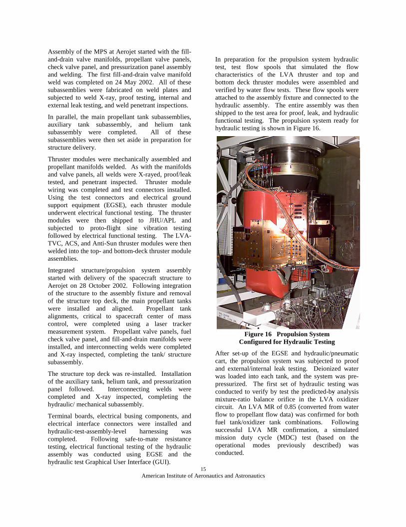
In preparation for the propulsion system hydraulic test, test flow spools that simulated the flow characteristics of the LVA thruster and top and bottom deck thruster modules were assembled and verified by water flow tests. These flow spools were attached to the assembly fixture and connected to the hydraulic assembly. The entire assembly was then shipped to the test area for proof, leak, and hydraulic functional testing. The propulsion system ready for hydraulic testing is shown in Figure 16.
Figure 16 Propulsion System Configured for Hydraulic Testing
After set-up of the EGSE and hydraulic/pneumatic cart, the propulsion system was subjected to proof and external/internal leak testing. Deionized water was loaded into each tank, and the system was pre-pressurized. The first set of hydraulic testing was conducted to verify by test the predicted-by- analysis mixture-ratio balance orifice in the LVA oxidizer circuit. An LVA MR of 0.85 (converted from water flow to propellant flow data) was confirmed for both fuel tank/oxidizer tank combinations. Following successful LVA MR confirmation, a simulated mission duty cycle (MDC) test (based on the operational modes previously described) was conducted.
16American Institute of Aeronautics and Astronautics
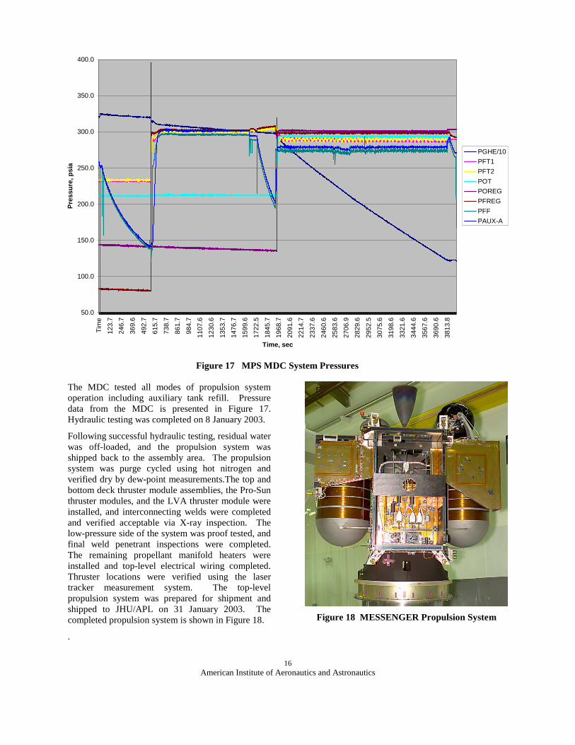
Figure 17 MPS MDC System Pressures
The MDC tested all modes of propulsion system operation including auxiliary tank refill. Pressure data from the MDC is presented in Figure 17. Hydraulic testing was completed on 8 January 2003.
Following successful hydraulic testing, residual water was off-loaded, and the propulsion system was shipped back to the assembly area. The propulsion system was purge cycled using hot nitrogen and verified dry by dew-point measurements.The top and bottom deck thruster module assemblies, the Pro-Sun thruster modules, and the LVA thruster module were installed, and interconnecting welds were completed and verified acceptable via X-ray inspection. The low-pressure side of the system was proof tested, and final weld penetrant inspections were completed. The remaining propellant manifold heaters were installed and top-level electrical wiring completed. Thruster locations were verified using the laser tracker measurement system. The top-level propulsion system was prepared for shipment and shipped to JHU/APL on 31 January 2003. The completed propulsion system is shown in Figure 18.
.
Figure 18 MESSENGER Propulsion System
50.0
100.0
150.0
200.0
250.0
300.0
350.0
400.0
Tim
e
123.
7
246.
7
369.
6
492.
7
615.
7
738.
7
861.
7
984.
7
1107
.6
1230
.6
1353
.7
1476
.7
1599
.6
1722
.5
1845
.7
1968
.7
2091
.6
2214
.7
2337
.6
2460
.6
2583
.6
2706
.9
2829
.6
2952
.5
3075
.6
3198
.6
3321
.6
3444
.6
3567
.6
3690
.6
3813
.8
Time, sec
Pre
ssu
re, p
sia
PGHE/10
PFT1
PFT2
POT
POREG
PFREG
PFF
PAUX-A

17American Institute of Aeronautics and Astronautics
Upon arrival at JHU/APL, the propulsion system was removed from its shipping pallet and visually inspected. Thermocouples were installed, and the system was placed in JHU/APL’s thermal vacuum chamber and subjected to an 86 hour, 50°C (122oF) thermal bake-out. After completing bake-out, the propulsion system was removed from the thermal vacuum chamber and placed on a handling dolly. Accelerometers were installed, and the propellant tanks were mass loaded with de-ionized water and pre-pressurized. The propulsion system was then subjected to a 5-150 Hz, 0.25-G sine modal survey in all three spacecraft axes. During vibration testing, the propulsion system was powered using the EGSE. After successful sine modal survey testing, the system was de-pressurized, water was off-loaded, and the system was again dried via purge cycling and warm GN2 flow through until a -40° C dew-point reading was obtained. Following a final set of electrical functional testing and internal leak checks, the propulsion system was handed over to the spacecraft integration team on 3 February 2003
CONCLUSION
This paper has described the design process from concept through delivery that produced one of the most robust, mass-efficient, highest Delta V propulsion systems developed to date. Preparation for the MESSENGER orbiter mission to the planet Mercury is well on its way. Following successful development, manufacture, test and integration of the propulsion system into the spacecraft structure, the integrated unit has been delivered to JHU/APL where the remaining spacecraft integration tasks are in process. The MESSENGER spacecraft, scheduled for launch in March 2004, will be powered by the MESSENGER propulsion system as it makes its five-year journey to Mercury, is inserted into the planet’s orbit, and remains there for one year, gathering key scientific data.
REFERENCES
1. W. H. Tam, K. T. Dommer, L. E. Mosher, D. F. Persons, and S. R. Wiley, “Design and Manufacture of the MESSENGER Propellant Tank Assembly,” AIAA Joint Propulsion Conference Paper #AIAA 2002-4139, July 2002.
2. Santo, A. G., R. E. Gold, R. L. McNutt, Jr., S. C. Solomon, C. J. Ercol, R. W. Farquhar, T. J. Hartka, J. E. Jenkins, J. V. McAdams, L. E. Mosher, D. F. Persons, D. A. Artis, R. S. Bokulic, R. F. Conde, G. Dakermanji, M. E. Goss, Jr., D. R. Haley, K. J. Heeres, R. H. Maurer, R. C. Moore, E. H. Rodberg, T. G. Stern, S. R. Wiley, B. G. Williams, C. L. Yen, and M. R. Peterson, The MESSENGER mission to Mercury: Spacecraft and mission design, Planet. Space Sci., 49, 1481-1500, 2001.