Design and Development of Sheet-Metal Elbows Using ...
23
symmetry S S Article Design and Development of Sheet-Metal Elbows Using Programming with Visual Basic for Applications in CATIA José Ignacio Rojas-Sola 1, * , Gloria del Río-Cidoncha 2 , Rafael Ortíz-Marín 2 and José MaríaLópez-Pedregal 3 Citation: Rojas-Sola, J.I.; del Río-Cidoncha, G.; Ortíz-Marín, R.; López-Pedregal, J.M. Design and Development of Sheet-Metal Elbows Using Programming with Visual Basic for Applications in CATIA. Symmetry 2021, 13, 33. https://dx. doi.org/10.3390/sym13010033 Received: 25 November 2020 Accepted: 24 December 2020 Published: 28 December 2020 Publisher’s Note: MDPI stays neu- tral with regard to jurisdictional claims in published maps and institutional affiliations. Copyright: © 2020 by the authors. Li- censee MDPI, Basel, Switzerland. This article is an open access article distributed under the terms and conditions of the Creative Commons Attribution (CC BY) license (https://creativecommons.org/ licenses/by/4.0/). 1 Department of Engineering Graphics, Design and Projects, University of Jaen, 23071 Jaen, Spain 2 Department of Engineering Graphics, University of Seville, 41092 Seville, Spain; [email protected] (G.d.R.-C.); [email protected] (R.O.-M.) 3 University of Seville, 41092 Seville, Spain; [email protected] * Correspondence: [email protected]; Tel.: +34-953-212452 Abstract: This article introduces an innovative application of Visual Basic for Applications (VBA) (Visual Basic macro language) developed in CATIA (Computer-Aided Three-Dimensional Interactive Application), computer-aided manufacturing and engineering design software. Said application enables the three-dimensional (3D) representation and development to be obtained on a plane of the surfaces of cylindrical and conical elbows utilised to join two conduits, since CATIA lacks tools for the design of elements of metal fabrication. The application permits the geometric and dimensional parameters necessary for the creation and development of the analysed elbows to be introduced via a keyboard. Once these values have been entered and it has been verified that the design of the elbow is possible, then the application is programmed within the CATIA “Wireframe and Surface Design” module to obtain the 3D representation of said elbows, and the development of their surface is projected in the CATIA “Drafting” module. Consequently, the incorporation of this tool into CATIA software could increase technical-design productivity by eliminating certain intermediate operations, such as symmetry, and through improving the geometry training of less skilled users. Keywords: elbows; computer-aided design; sheet metal; development; Visual Basic; CATIA 1. Introduction Advances in engineering graphics, as a fundamental part of the computer-aided design process, are ongoing [1], as are the advances in the use of computer-aided design (CAD) techniques in the geometric modelling process [2–4]. One of its main applications involves obtaining the development stamped onto metal sheet (metal fabrication) to form surfaces that can be used in industry; subsequently and by means of computer-aided manufacturing (CAM) software, this stamped development can be adapted to cutting machines using computer numerical control (CNC). Metal fabrication is the branch of the industry in which the most diverse constructions are made in metal or in metallic alloys, from sheets of various shapes and thicknesses. It is subdivided into three large sectors depending on the thickness of the sheet or plate used and the dimensions of the profiles: light, medium, and heavy metal fabrication, and consists of the manufacture and assembly of conduits and containers used in the storage and conduction of aggregates and fluids [5]. The most common elements are cylindrical and polygonal conduits, concentric and eccentric reductions, adapter surfaces, hoppers, and elbows. These can be classified into two groups: developable and warped surfaces (parts). The first are those that can be extended on a single plane to obtain the form of the material before shaping; the latter are those that cannot be extended on a plane and, therefore, are obtained by approximate drawing methods, and require special shaping operations such as embossing, stamping, and pumping. Symmetry 2021, 13, 33. https://dx.doi.org/10.3390/sym13010033 https://www.mdpi.com/journal/symmetry
Transcript of Design and Development of Sheet-Metal Elbows Using ...

symmetryS S
Article
Design and Development of Sheet-Metal Elbows UsingProgramming with Visual Basic for Applications in CATIA
José Ignacio Rojas-Sola 1,* , Gloria del Río-Cidoncha 2, Rafael Ortíz-Marín 2 and José María López-Pedregal 3
�����������������
Citation: Rojas-Sola, J.I.; del
Río-Cidoncha, G.; Ortíz-Marín, R.;
López-Pedregal, J.M. Design and
Development of Sheet-Metal Elbows
Using Programming with Visual
Basic for Applications in CATIA.
Symmetry 2021, 13, 33. https://dx.
doi.org/10.3390/sym13010033
Received: 25 November 2020
Accepted: 24 December 2020
Published: 28 December 2020
Publisher’s Note: MDPI stays neu-
tral with regard to jurisdictional claims
in published maps and institutional
affiliations.
Copyright: © 2020 by the authors. Li-
censee MDPI, Basel, Switzerland. This
article is an open access article distributed
under the terms and conditions of the
Creative Commons Attribution (CC BY)
license (https://creativecommons.org/
licenses/by/4.0/).
1 Department of Engineering Graphics, Design and Projects, University of Jaen, 23071 Jaen, Spain2 Department of Engineering Graphics, University of Seville, 41092 Seville, Spain; [email protected] (G.d.R.-C.);
[email protected] (R.O.-M.)3 University of Seville, 41092 Seville, Spain; [email protected]* Correspondence: [email protected]; Tel.: +34-953-212452
Abstract: This article introduces an innovative application of Visual Basic for Applications (VBA)(Visual Basic macro language) developed in CATIA (Computer-Aided Three-Dimensional InteractiveApplication), computer-aided manufacturing and engineering design software. Said applicationenables the three-dimensional (3D) representation and development to be obtained on a plane of thesurfaces of cylindrical and conical elbows utilised to join two conduits, since CATIA lacks tools forthe design of elements of metal fabrication. The application permits the geometric and dimensionalparameters necessary for the creation and development of the analysed elbows to be introducedvia a keyboard. Once these values have been entered and it has been verified that the design of theelbow is possible, then the application is programmed within the CATIA “Wireframe and SurfaceDesign” module to obtain the 3D representation of said elbows, and the development of their surfaceis projected in the CATIA “Drafting” module. Consequently, the incorporation of this tool into CATIAsoftware could increase technical-design productivity by eliminating certain intermediate operations,such as symmetry, and through improving the geometry training of less skilled users.
Keywords: elbows; computer-aided design; sheet metal; development; Visual Basic; CATIA
1. Introduction
Advances in engineering graphics, as a fundamental part of the computer-aideddesign process, are ongoing [1], as are the advances in the use of computer-aided design(CAD) techniques in the geometric modelling process [2–4].
One of its main applications involves obtaining the development stamped onto metalsheet (metal fabrication) to form surfaces that can be used in industry; subsequently andby means of computer-aided manufacturing (CAM) software, this stamped developmentcan be adapted to cutting machines using computer numerical control (CNC).
Metal fabrication is the branch of the industry in which the most diverse constructionsare made in metal or in metallic alloys, from sheets of various shapes and thicknesses.It is subdivided into three large sectors depending on the thickness of the sheet or plateused and the dimensions of the profiles: light, medium, and heavy metal fabrication, andconsists of the manufacture and assembly of conduits and containers used in the storageand conduction of aggregates and fluids [5].
The most common elements are cylindrical and polygonal conduits, concentric andeccentric reductions, adapter surfaces, hoppers, and elbows. These can be classified intotwo groups: developable and warped surfaces (parts). The first are those that can beextended on a single plane to obtain the form of the material before shaping; the latterare those that cannot be extended on a plane and, therefore, are obtained by approximatedrawing methods, and require special shaping operations such as embossing, stamping,and pumping.
Symmetry 2021, 13, 33. https://dx.doi.org/10.3390/sym13010033 https://www.mdpi.com/journal/symmetry

Symmetry 2021, 13, 33 2 of 23
A number of the scientific publications on the development and manufacture of sheet-metal parts have dealt with the subject from different points of view. These range from toolsfor the design of sheet-metal parts with Solid Edge as educational tools [6], and assistedmanufacturing for drawing sheet-metal parts [7], to visual inspection techniques with CADdata [8], manufacturing technologies from CAD files [9], the application of CAD/CAMtechnology in the development and lofting of complex sheet parts [10], robot-assistedsheet-metal bending with off-line programming and simulation from CAD drawings [11],and the automatic import of XML files with optimised geometric information from 3DCAD models of sheet-metal parts [12].
State-of-the-Art of the Existing Related Software
At present there are various commercial tools in different graphic environments thatenable the true magnitude developments of various elements used in industrial metalfabrication in order to automate sheet-metal cutting processes. To this end, these tools basetheir operation on the selection of the specific type of element, and on the introduction ofthe geometric data necessary for its definition and the procurement of its development.
After an exhaustive review of these tools, the main applications to obtain sheet-metaldevelopments are listed below.
• Galileo [13]
This is a vertical application designed to trace the developments of the most commonlyused elements (hoppers, elbows, bifurcations, and various cuts by planes, among others)in the metal fabrication industry. This application works entirely within the AutoCAD andMicroStation environment, with an AutoCAD drawing file (.dwg) output format and canbe exported by means of an interchange file (neutral file) (.dxf).
In this way, by means of a plotter output, either an optical copier is employed toautomatically generate the cutting path, or this file can be sent to a numerical controlmachine for greater automation.
• Lantek Expert [14]
This is a powerful module for the automatic tracing of sheet-metal elements. It in-cludes an extensive library of parameterised figures that follow DIN and SMACNA stan-dards (hoppers, cones, cylinders, elbows, etc.), where practically all the elements used canbe found.
This tool integrates a two-dimensional (2D) CAD module for the design of any part,as well as for the geometric modification of the drawings. Lantek Expert also enablescutting or punching the development of the figure based on flanges, notches, and fold linesfor marking.
This module connects with many CAD systems through a variety of formats (such as.dwg), or via neutral files (such as .dxf and .iges).
• LogiTRACE [15]
This is software for the design of conduits, components, and tools for ventilationand heating systems. It is an application designed to help in the metalworking industry.Elbows, reductions, conductors, and transitions are included in the many elements thatcan be designed with LogiTRACE.
The program asks the user for the data necessary for its design, so that LogiTRACEcan automatically calculate, draw, and dimension out the development of the element tocut the metal sheet.
• LITIO 2.0 [16]
This is a design software that obtains the development in sheet metal (with metalssuch as iron, stainless steel, brass, copper, and aluminium) of multiple metal fabricationelements. It is a program for AutoCAD/GStarCAD and is used to design hoppers, cyclones,conduits, silos, tubes, air conditioning, ventilation and heating installations, dust-extractioninstallations, and transport systems.

Symmetry 2021, 13, 33 3 of 23
• Plate’n’Sheet [17]
This is manufacturing software for metal fabrication designs. The result can beexported in neutral format (.dxf) to the machining software of a numerical control machine.The design can also be printed on a 1:1 scale to create a template or to obtain a table ofpoints to mark directly onto a metal plate to be cut with a manual machine. It has anextensive library with almost 200 elements.
First, the user selects the element to trace and enters its dimensions. Likewise, param-eters are established such as sheet thickness, separation for cutting, type of joint, and theconstruction parameters: type of development and number of bending lines.
The software then analyses the coherence of the values entered and reports on anyinconsistencies. The outputs it provides include the 3D view, the design to optimise thematerial, the design to align joins, templates, measurements, and design dimensioning.
Having carried out the review, it was revealed that none of said software applicationshas been programmed in the CATIA (Computer-Aided Three-Dimensional InteractiveApplication) environment, which is one of the most widely used commercial computer-aided design, manufacturing and engineering software. Hence, the convenience andoriginality of this research lies in including this environment for the manufacture of sheet-metal elbows.
This research makes it possible to underline the importance of the application devel-oped both from a commercial and educational point of view, since it could be used for CADteaching purposes in design-related schools and institutions worldwide. Consequently,the incorporation of this tool into CATIA could increase technical-design productivityby eliminating certain intermediate operations, such as symmetry, and by improving thegeometry training of less skilled users.
The remainder of the paper is structured as follows: Section 2 presents the sheet-metalelbows. Section 3 shows the materials and methods used in this investigation. Section 4includes the main results and discussion, while Section 5 states the main conclusions.
2. Sheet-Metal Elbows
Undoubtedly, one of the numerous and most important examples that can be shownin metal fabrication involves the elbows or union of two conduits. For example, whentheir axes cross and a change of direction is produced, this can be carried out directly byextending the conduits until they intersect.
However, if the angle between the axes of the conduits is not very large, then thisconstruction is not feasible since blockages, load losses, and hydraulic shock could occurwhen aggregates or fluids circulate. Therefore, in the majority of cases, it is decided to placeone or more intermediate parts (ferrules) that aid circulation. The set of these intermediateparts is called an elbow, and for economic reasons, said elbow is made with the leastnumber of ferrules possible.
The elbows can be cylindrical or conical, depending on whether the conduits tobe joined are cylinders of the same diameter or of different diameters, respectively and,whenever possible, they will be resolved by cylinders and cones of revolution [18].
2.1. Cylindrical Elbow
The theoretical foundation for the resolution of this type of elbow is based on thepossibility of obtaining the number of parts necessary for the construction of the elbowfrom the same cylinder (Figure 1). Although cylindrical elbows can be solved by means ofrevolution cylinders or by oblique cylinders with a circular base, it is more advisable to userevolution cylinders due to their easy construction, despite the drawback that none of theparts of the elbow are the same size. The oblique cylinder with a circular base, however,has the drawback of its constructional difficulty, despite the fact that all the parts of theelbow are of the same size [18].

Symmetry 2021, 13, 33 4 of 23
Symmetry 2021, 13, x FOR PEER REVIEW 4 of 24
the parts of the elbow are the same size. The oblique cylinder with a circular base, how-ever, has the drawback of its constructional difficulty, despite the fact that all the parts of the elbow are of the same size [18].
Figure 1. Theoretical foundation of a cylindrical elbow.
If said cylinder is cut by a vertical projecting plane (𝛼′) that passes through half its height, then the cylinder will be divided into two parts (I and II). If the upper part (IIg) is rotated so that both parts are symmetrical with respect to the projecting plane, then it can be observed that the angle 𝜔 formed by the axes of both parts is: 𝜔 = 2𝛽 (1)
Likewise, it can be observed that between the part (II) and its rotated part (II𝑔) there is an axial symmetry with respect to an axis perpendicular to the cutting plane that passes through the intersection point of the axes (O′). Therefore, the angle (θ) formed by the planes of the circular openings is supplementary to the angle 𝜔 formed by the axes: θ = 180° − 𝜔 = 180° − 2𝛽 (2)
Either of expressions (1) or (2) enable the calculation of the angle of inclination 𝛽 of the cutting plane 𝛼′ in order to obtain a two-part elbow whose axes form angle 𝜔 or whose circular openings form angle θ.
Furthermore, it is verified that the development of a cylindrical elbow can be ob-tained from a single cylinder of revolution of height ℎ, by cutting it across a vertical pro-jecting plane (𝛼′) that passes through the midpoint of its axis, thereby forming angle 𝛽 with said axis.
To this end, starting from a rectangular metal sheet of dimensions (2𝜋𝑅) × (ℎ), it is cut by the transform of the section of the plane 𝛼′ (a sine curve), and the sheet is then rolled to the diameter of the cylinder (Figure 2).
Figure 1. Theoretical foundation of a cylindrical elbow.
If said cylinder is cut by a vertical projecting plane (α′) that passes through half itsheight, then the cylinder will be divided into two parts (I and II). If the upper part (IIg) isrotated so that both parts are symmetrical with respect to the projecting plane, then it canbe observed that the angleω formed by the axes of both parts is:
ω = 2β (1)
Likewise, it can be observed that between the part (II) and its rotated part (IIg) there isan axial symmetry with respect to an axis perpendicular to the cutting plane that passesthrough the intersection point of the axes (O′). Therefore, the angle (θ) formed by theplanes of the circular openings is supplementary to the angleω formed by the axes:
θ = 180◦ − ω = 180◦ − 2β (2)
Either of expressions (1) or (2) enable the calculation of the angle of inclination β ofthe cutting plane α′ in order to obtain a two-part elbow whose axes form angleω or whosecircular openings form angle θ.
Furthermore, it is verified that the development of a cylindrical elbow can be obtainedfrom a single cylinder of revolution of height h, by cutting it across a vertical projectingplane (α′) that passes through the midpoint of its axis, thereby forming angle β withsaid axis.
To this end, starting from a rectangular metal sheet of dimensions (2πR) × (h), it is cutby the transform of the section of the plane α′ (a sine curve), and the sheet is then rolled tothe diameter of the cylinder (Figure 2).

Symmetry 2021, 13, 33 5 of 23Symmetry 2021, 13, x FOR PEER REVIEW 5 of 24
Figure 2. Theoretical development of a cylindrical elbow.
2.2. Conical Elbow This type of elbow is used to join two cylindrical conduits that present different di-
ameters. Conical elbows are always solved by cones of revolution of the same conicity, either by the procedure of circumscribed traverse elbows (the elbow elements are different sizes) or inscribed traverse elbows (the elbow elements are of the same height).
The procedure for drawing circumscribed polygonal elbows (Figure 3) consists, as in the case of a circumscribed cylindrical elbow, of dividing the angle formed by the planes of the circular openings (δ) by twice the number of ferrules (n) minus two: 𝑝 = 𝛿2𝑛 − 2 (3)
By the points of equal division, tangents to the arc of the elbow are drawn, and by the points (O’I) and (O’II) they are drawn perpendicular to the circular openings, thereby obtaining the circumscribed polygonal (O’I, O’1, O’2, O’3, O’II).
Subsequently, a truncated cone is built whose height is the perimeter of the polygon and the diameter of the conduits as the bases. Through the points (O’1, O’2, O’3), spheres are drawn inscribed onto the truncated cone of radii (R1, R2, R3).
Finally, the tangents to these spheres are drawn, thereby obtaining the apparent con-tour of the elbow, and in this way, through the intersections of the generatrices of the cone trunks, the ferrules are obtained [18].
Figure 2. Theoretical development of a cylindrical elbow.
2.2. Conical Elbow
This type of elbow is used to join two cylindrical conduits that present differentdiameters. Conical elbows are always solved by cones of revolution of the same conicity,either by the procedure of circumscribed traverse elbows (the elbow elements are differentsizes) or inscribed traverse elbows (the elbow elements are of the same height).
The procedure for drawing circumscribed polygonal elbows (Figure 3) consists, as inthe case of a circumscribed cylindrical elbow, of dividing the angle formed by the planes ofthe circular openings (δ) by twice the number of ferrules (n) minus two:
p =δ
2n− 2(3)
By the points of equal division, tangents to the arc of the elbow are drawn, and bythe points (O’I) and (O’II) they are drawn perpendicular to the circular openings, therebyobtaining the circumscribed polygonal (O’I, O’1, O’2, O’3, O’II).
Subsequently, a truncated cone is built whose height is the perimeter of the polygonand the diameter of the conduits as the bases. Through the points (O’1, O’2, O’3), spheresare drawn inscribed onto the truncated cone of radii (R1, R2, R3).
Finally, the tangents to these spheres are drawn, thereby obtaining the apparentcontour of the elbow, and in this way, through the intersections of the generatrices of thecone trunks, the ferrules are obtained [18].
It is observed that the development of the conical elbow can be obtained from thesurface of the single truncated cone (Figure 4).

Symmetry 2021, 13, 33 6 of 23Symmetry 2021, 13, x FOR PEER REVIEW 6 of 24
Figure 3. Theoretical foundation of a conical elbow.
It is observed that the development of the conical elbow can be obtained from the surface of the single truncated cone (Figure 4).
Figure 3. Theoretical foundation of a conical elbow.

Symmetry 2021, 13, 33 7 of 23Symmetry 2021, 13, x FOR PEER REVIEW 7 of 24
Figure 4. Theoretical development of a conical elbow.
3. Material and Methods 3.1. Design and Development of Sheet-Metal Elbows in CATIA 3.1.1. Cylindrical Elbows
In order to explain the steps necessary to draw and develop a cylindrical elbow, an elbow of 90° formed of 4 ferrules has been chosen as an example [19]. Design
Figure 5 shows the various steps to follow. In order to create the design, it is necessary to first draw the inlet and outlet of the
conduits to be connected. In Figure 5a, it can be observed that the horizontal and vertical distances between the
centres of the two conduits are not equal, and therefore the elbow is extruded through the opening of conduit 2 until an arc can be traced that is tangent at the midpoint of both conduits.
In accordance with Equation (3), the angle between the two conduits (90°) is divided into twice the number of ferrules (4) minus two, resulting in an angle of 15°.
In Figure 5b, the six divisions needed to draw the elbow can be observed. Note that auxiliary lines perpendicular to the equal divisions of the 90° angle have also been drawn, which represent the axes of the ferrules; these will be used later.
Finally, in Figure 5c, the last step, which consists of extending the conduits to the divisions, is observed, thereby forming the 4 ferrules, and obtaining the final result of the elbow. The inlet and outlet conduits are extended to their first division and form simple ferrules. However, the two intermediate ferrules are drawn parallel to the axes described above and are considered to be double ferrules due to the fact that they each contain two divisions.
Figure 4. Theoretical development of a conical elbow.
3. Material and Methods3.1. Design and Development of Sheet-Metal Elbows in CATIA3.1.1. Cylindrical Elbows
In order to explain the steps necessary to draw and develop a cylindrical elbow,an elbow of 90◦ formed of 4 ferrules has been chosen as an example [19].
Design
Figure 5 shows the various steps to follow.In order to create the design, it is necessary to first draw the inlet and outlet of the
conduits to be connected.In Figure 5a, it can be observed that the horizontal and vertical distances between
the centres of the two conduits are not equal, and therefore the elbow is extruded throughthe opening of conduit 2 until an arc can be traced that is tangent at the midpoint of bothconduits.
In accordance with Equation (3), the angle between the two conduits (90◦) is dividedinto twice the number of ferrules (4) minus two, resulting in an angle of 15◦.
In Figure 5b, the six divisions needed to draw the elbow can be observed. Note thatauxiliary lines perpendicular to the equal divisions of the 90◦ angle have also been drawn,which represent the axes of the ferrules; these will be used later.
Finally, in Figure 5c, the last step, which consists of extending the conduits to thedivisions, is observed, thereby forming the 4 ferrules, and obtaining the final result of theelbow. The inlet and outlet conduits are extended to their first division and form simpleferrules. However, the two intermediate ferrules are drawn parallel to the axes describedabove and are considered to be double ferrules due to the fact that they each contain twodivisions.

Symmetry 2021, 13, 33 8 of 23Symmetry 2021, 13, x FOR PEER REVIEW 8 of 24
(a) (b)
(c)
Figure 5. Steps to follow when drawing a 90° cylindrical elbow with four ferrules.
Development At this stage, we proceed to explain how to develop said cylindrical elbow on the
plane, by using the necessary metal sheet for its construction (Figure 6). First, the conduit inlet is drawn, and the semicircle is divided into eight equal parts,
that is, it is divided into eight angles of 22.5° each (Figure 6a). On the other hand, a rec-tangle is drawn, which represents the sheet necessary for the manufacture of the elbow, whose base is the length of the circumference and whose height is the same as that of the complete cylinder. This sheet is divided with vertical lines into 16 equal parts; only the first 8 divisions are shown, however, since the right-hand side will be symmetrical to the left-hand side. For clarification, the height of the cylinder (H) is obtained as the sum of all the segments of the axes of the ferrules.
Subsequently, vertical lines are drawn from the divisions of the semicircle to the cut between the first and second ferrules, and these points are projected horizontally onto the divisions made on the sheet (Figure 6b).
These last intersection points are then joined, thereby forming the design of the joint between the first two ferrules. It should be borne in mind that by increasing the number of divisions of the circumference, a greater number of points would be obtained and, therefore, greater precision in the design.
Opening 2
Opening 1
Figure 5. Steps to follow when drawing a 90◦ cylindrical elbow with four ferrules.
Development
At this stage, we proceed to explain how to develop said cylindrical elbow on theplane, by using the necessary metal sheet for its construction (Figure 6).
First, the conduit inlet is drawn, and the semicircle is divided into eight equal parts,that is, it is divided into eight angles of 22.5◦ each (Figure 6a). On the other hand, arectangle is drawn, which represents the sheet necessary for the manufacture of the elbow,whose base is the length of the circumference and whose height is the same as that of thecomplete cylinder. This sheet is divided with vertical lines into 16 equal parts; only thefirst 8 divisions are shown, however, since the right-hand side will be symmetrical to theleft-hand side. For clarification, the height of the cylinder (H) is obtained as the sum of allthe segments of the axes of the ferrules.
Subsequently, vertical lines are drawn from the divisions of the semicircle to the cutbetween the first and second ferrules, and these points are projected horizontally onto thedivisions made on the sheet (Figure 6b).
These last intersection points are then joined, thereby forming the design of the jointbetween the first two ferrules. It should be borne in mind that by increasing the number ofdivisions of the circumference, a greater number of points would be obtained and, therefore,greater precision in the design.
Once that part of the design has been drawn, the rest can be obtained thanks tosymmetry. In this way, it can be deduced that the design of the subsequent ferrules willbe symmetrical with respect to the dividing lines of the arc, that is to say, if these lines areprojected onto the metal sheet, then the rest of the design can be obtained (Figure 6c).

Symmetry 2021, 13, 33 9 of 23Symmetry 2021, 13, x FOR PEER REVIEW 9 of 24
(a) (b)
(c) (d)
Figure 6. Steps to follow in the development of a 90° cylindrical elbow with four ferrules.
Once that part of the design has been drawn, the rest can be obtained thanks to sym-metry. In this way, it can be deduced that the design of the subsequent ferrules will be symmetrical with respect to the dividing lines of the arc, that is to say, if these lines are projected onto the metal sheet, then the rest of the design can be obtained (Figure 6c).
Finally, the same procedure is repeated until the design of all the ferrules is obtained. In Figure 6d, the final result of the development of this cylindrical elbow is shown, and the shape of the metal sheet of each of the ferrules can be appreciated.
3.1.2. Conical Elbows In this section, the same procedure will be carried out to explain the design and de-
velopment of a conical elbow [19]. As an example, a 90° conical elbow with 4 ferrules has been selected, whose inlet conduit is twice the diameter of the outlet conduit. Design
In Figure 7, the different steps to follow can be observed. Actually, it is the application of the method of bitangent spheres that determine elements constituted by cones of revo-lution, and which is based on the property that two equal cones of revolution tangent to the same sphere, can be made to coincide by turning the ellipse section 180° on its same plane, around its centre.
In the auxiliary construction where the truncated cone of revolution which axis is equal to the sum of the sides of the polygonal formed by opening 1 + A + B + C + opening 2 and which base are the diameters of opening 1 and 2 has been drawn, then the spheres of centres A, B and C inscribed in it are drawn. It is evident that the four ferrules belong to the truncated cone since they are circumscribed to the spheres of centres A, B and C.
Figure 6. Steps to follow in the development of a 90◦ cylindrical elbow with four ferrules.
Finally, the same procedure is repeated until the design of all the ferrules is obtained.In Figure 6d, the final result of the development of this cylindrical elbow is shown, and theshape of the metal sheet of each of the ferrules can be appreciated.
3.1.2. Conical Elbows
In this section, the same procedure will be carried out to explain the design anddevelopment of a conical elbow [19]. As an example, a 90◦ conical elbow with 4 ferruleshas been selected, whose inlet conduit is twice the diameter of the outlet conduit.
Design
In Figure 7, the different steps to follow can be observed. Actually, it is the applicationof the method of bitangent spheres that determine elements constituted by cones of revolu-tion, and which is based on the property that two equal cones of revolution tangent to thesame sphere, can be made to coincide by turning the ellipse section 180◦ on its same plane,around its centre.
In the auxiliary construction where the truncated cone of revolution which axis isequal to the sum of the sides of the polygonal formed by opening 1 + A + B + C + opening2 and which base are the diameters of opening 1 and 2 has been drawn, then the spheres ofcentres A, B and C inscribed in it are drawn. It is evident that the four ferrules belong tothe truncated cone since they are circumscribed to the spheres of centres A, B and C. Forthis reason, the common mouths of the ferrules can be made to coincide by turning them180◦ and so on until obtaining the truncated cone.
Likewise, the sides of the polygonal (opening 1 + A + B + C + opening 2) will coincidewith the axes of the cones, as they are the lines that join the centres of the spheres inscribedin them.
Symmetry 2021, 13, 33 10 of 23
Symmetry 2021, 13, x FOR PEER REVIEW 10 of 24
For this reason, the common mouths of the ferrules can be made to coincide by turning them 180° and so on until obtaining the truncated cone.
Likewise, the sides of the polygonal (opening 1 + A + B + C + opening 2) will coincide with the axes of the cones, as they are the lines that join the centres of the spheres inscribed in them.
(a) (b)
(c) (d)
Figure 7. Steps to follow when designing a 90° conical elbow with four ferrules.
In Figure 7a, it can be appreciated how these conduits are positioned. In this case, the horizontal and vertical distances between the centres of the two conduits are equal, and hence neither conduit requires extrusion.
As in the case of the cylindrical elbow, the arc that joins the two conduits is divided into angles of 15° (3), thereby drawing the auxiliary lines perpendicular to the equal divi-sions of the angle.
As explained previously, these lines represent the axes of the ferrules, and therefore, they are transferred to construct the truncated cone with bases the diameters of the con-duits (Figure 7b).
Inscribed circumferences are subsequently drawn on the truncated cone at points A, B, and C, in such a way that the diameter of the inscribed circumferences on the ferrules is obtained. In the next step, these circumferences are transferred to the centres B’ and C’, so that the ferrules can be drawn.
C
C’
B B’
A
Figure 7. Steps to follow when designing a 90◦ conical elbow with four ferrules.
In Figure 7a, it can be appreciated how these conduits are positioned. In this case, thehorizontal and vertical distances between the centres of the two conduits are equal, andhence neither conduit requires extrusion.
As in the case of the cylindrical elbow, the arc that joins the two conduits is dividedinto angles of 15◦ (3), thereby drawing the auxiliary lines perpendicular to the equaldivisions of the angle.
As explained previously, these lines represent the axes of the ferrules, and therefore,they are transferred to construct the truncated cone with bases the diameters of the conduits(Figure 7b).
Inscribed circumferences are subsequently drawn on the truncated cone at points A,B, and C, in such a way that the diameter of the inscribed circumferences on the ferrules isobtained. In the next step, these circumferences are transferred to the centres B’ and C’, sothat the ferrules can be drawn.
In Figure 7c, it can be observed that the inscribed circumferences have been transferredand that the tangent lines between them have also been drawn. After tracing these lines,drawing can start on the ferrules by simply joining the intersection points between thetangent lines.
Finally, the same procedure is carried out for the remaining ferrules, thereby obtainingthe conical elbow (Figure 7d).
Symmetry 2021, 13, 33 11 of 23
Development
In this section, it is explained how to develop said conical elbow on the plane, giventhe necessary metal sheet for its construction (Figure 8). On this occasion, the elbow comesfrom a truncated cone, and not from a cylinder as in the previous case. Therefore, thedevelopment to be obtained will not be on a rectangle, but instead will be obtained on thesurface of a truncated cone.
Symmetry 2021, 13, x FOR PEER REVIEW 11 of 24
In Figure 7c, it can be observed that the inscribed circumferences have been trans-ferred and that the tangent lines between them have also been drawn. After tracing these lines, drawing can start on the ferrules by simply joining the intersection points between the tangent lines.
Finally, the same procedure is carried out for the remaining ferrules, thereby obtain-ing the conical elbow (Figure 7d).
Development In this section, it is explained how to develop said conical elbow on the plane, given
the necessary metal sheet for its construction (Figure 8). On this occasion, the elbow comes from a truncated cone, and not from a cylinder as in the previous case. Therefore, the development to be obtained will not be on a rectangle, but instead will be obtained on the surface of a truncated cone.
(a) (b)
(c) (d)
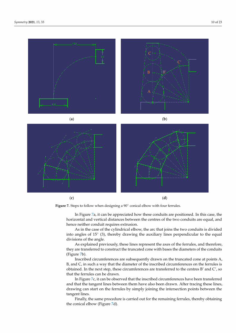
Figure 8. Steps to follow in developing a 90° conical elbow with four ferrules.
First, the truncated cone is drawn by transferring the construction of the drawing (Figure 8a).
𝑉 𝑉’
2𝜋𝑑
2𝜋𝐷
Figure 8. Steps to follow in developing a 90◦ conical elbow with four ferrules.
First, the truncated cone is drawn by transferring the construction of the drawing(Figure 8a).
Subsequently, in a similar way to the case of the cylindrical elbow, a semicircle of thelargest diameter is drawn and divided into 4 equal parts, that is, at 45◦ angles.
On the other hand, the vertex (V) of the cone is obtained by prolonging the generatrices.This vertex is transferred towards point V”, and the development is created on the plane ofthe truncated cone, by dividing it into 8 equal parts (Figure 8b).
In the next step (Figure 8c), the divisions of the semicircle are projected vertically ontothe base, and then to the vertex of the cone. The intersection points that are produced with
Symmetry 2021, 13, 33 12 of 23
the separations between the ferrules are projected horizontally up to the development ofthe cone. These last intersection points are joined to form the development of the jointbetween the ferrules.
Finally (Figure 8d), the same procedure is followed and the symmetry regardingthe central generatrix of the development of the cone is employed in order to obtain thedevelopment of the ferrules of the conical elbow.
3.2. Programming Environment with Visual Basic for Applications (VBA)
Microsoft Visual Basic (VB) is an event-driven programming language, developedby Alan Cooper for Microsoft, while Microsoft VBA (Visual Basic for Applications) is themacro language for Microsoft Visual Basic. Its main utility is to automate daily tasks, andto create applications and database services for the desktop.
In 1998, CATIA, in the V5 version, incorporated VBA into its environment, and wasable to carry out macros in Visual Basic [20] and in the C++ language; these remain themacro programming languages available in the V6 version.
A macro consists of a series of functions written in a programming language thatgroups together a series of commands that allow the required operations to be carried outautomatically.
The use of macros for automation in the design process is practically unlimited.Examples thereof include the import of points from Excel to a 3D CAD model, the automaticgeneration of geometries, and the creation of 3D model drawings, among others.
As indicated, CATIA V5 has the ability to work in the VBA environment. This canbe carried out from any module by opening the “Tools” tab, where the “Macro” optionappears, within which it is possible to start recording a macro or access the macros alreadycreated, and to access libraries or the Visual Basic editor [20].
CATIA macros are stored in macro libraries in one of three ways: Folders (vbscriptand CATScript); Project files (catvba); or as documents such as CATParts, CATProducts, andCATDrawings. Only one of these three macro libraries can be used at a time.
In this way, the CATScript files will be saved in the library created. This only needsto be carried out once, and from then on, the library remains loaded even after restartingCATIA [18].
One method of creating macros is to record actions performed with the mouse. Formacros recorded in a file, in a CATpart or CATproduct, the declared statements (instructionscontaining mathematical operators, variables, constants, expressions, loops, functions, andsub-functions) will be recorded for CATScript, but not for MSVBscript. However, macroscannot be recorded using CATIA ‘Drafting’ module.
In the present investigation, all the codes have been carried out using the option todevelop macros that CATIA V5 presents, that is, by means of the Visual Basic editor [20].
3.3. Steps to Follow3.3.1. Work Environment
In order to start on the code, the work environment is first set to CATIA. In this way, anew element Part can be initiated directly from the application. The necessary statementsare the following:
Dim documents1 As DocumentsSet documents1 = CATIA.DocumentsDim partDocument1 As PartDocumentSet partDocument1 = documents1.Add(“Part”)Dim part1 As PartSet part1 = partDocument1.Part
A new document, the PartDocument object, is created with the Documents object, whichenables the CATIA ‘Wireframe and Surface Design’ module to be activated and, finally,the file where the elbow will be designed is created with the Part object. Subsequently, the

Symmetry 2021, 13, 33 13 of 23
operations tree is defined where all the operations and objects that are created in the filewill be reflected. In this way, the Bodies object is established and within it a Body is defined.
3.3.2. Definition of Sketch
In order to start drawing any part in CATIA, a sketch on the plane must first be madeto later generate the part in 3D.
The Sketch is created within the previous Body and the reference system refers to wherethe Sketch is to be located. Subsequently, the directions that form the Sketch plane areindicated with a matrix.
Dim sketches1 As SketchesSet sketches1 = body1.SketchesDim originElements1 As OriginElementsSet originElements1 = part1.OriginElements Dim reference1 As ReferenceSet reference1 = originElements1.PlaneXY Dim sketch1 As SketchSet sketch1 = sketches1.Add(reference1)Dim arrayOfVariantOfDouble1(8) arrayOfVariantOfDouble1(0) = 0#arrayOfVariantOfDouble1(1) = 0#arrayOfVariantOfDouble1(2) = 0#arrayOfVariantOfDouble1(3) = 1#arrayOfVariantOfDouble1(4) = 0#arrayOfVariantOfDouble1(5) = 0#arrayOfVariantOfDouble1(6) = 0#arrayOfVariantOfDouble1(7) = 1#arrayOfVariantOfDouble1(8) = 0#Set sketch1Variant = sketch1 sketch1Variant.SetAbsoluteAxisData arrayOfVariantOfDouble1part1.InWorkObject = sketch1
With the InWorkObject command, it is defined that the workplace from then on isinside sketch1. Finally, to finish defining the sketch, the set of geometric elements and tools,axes and directions are established.
Dim factory2D1 As Factory2DSet factory2D1 = sketch1.OpenEdition()Dim geometricElements1 As GeometricElementsSet geometricElements1 = sketch1.GeometricElementsDim axis2D1 As Axis2DSet axis2D1 = geometricElements1.Item(“AbsoluteAxis”)Dim line2D1 As Line2DSet line2D1 = axis2D1.GetItem(“HDirection”) Dim line2D2 As Line2DSet line2D2 = axis2D1.GetItem(“VDirection”)
Within the factory2D object, all the necessary methods to be able to work and createthe geometries are included (point, line, circumference, projection, spline, closed circle,ellipse, closed ellipse, hyperbola, parabola, control point, intersection, etc.). The followingexamples show lines of code for the creation of three of these geometries:
Creation of a point (using its coordinates)
Dim point2D1 As Point2DSet point2D1 = factory2D1.CreatePoint(coord_x, coord_y)point2D1.Construction = False
Creation of a line (using two points)Dim line2D1 As Line2DSet line2D1 = factory2D1.CreateLine(x1, y1, x2, y2)line2D1.Construction = Trueline2D1.StartPoint = point2D1line2D1.EndPoint = point2D2
Creation of a circumference (using the coordinate of the centre and the radius)

Symmetry 2021, 13, 33 14 of 23
Dim circle2D1 As Circle2DSet circle2D1 = factory2D1.CreateClosedCircle(x1, y1, r1)circle2D1.CentrePoint = point2D1
3.3.3. ConstraintsOnce the geometric elements have been drawn in the Sketch, it is necessary to leave all
the elements well-defined and fixed, so that nothing can be altered when introducing anyother element. This is achieved by setting Constraints.
In order to establish a constraint, it is first necessary to reference the objects to be set,and once the references have been defined, a command is executed that relates them to eachother. Commands can relate one, two, and up to three different references to each other.
There are up to 31 types of constraints (symmetry, radius, equidistance, distance,concentricity, length, angle, tangency, parallelism, perpendicularity, midpoint, etc.), eachwith its corresponding lines of code.
3.3.4. CATIA ‘Wireframe and Surface Design’ Module
This section explains the CATIA ‘Wireframe and Surface Design’ module, whichcontains all the tools necessary for the generation of wireframe geometry and basic surfaces.
Surfaces are elements called HybridBodies and are found within the Part schema.Within the HybridBodies, the HybridShapeFactory objects are defined, which are those thatcontain all the tools necessary to work with surfaces.
The main tools for working with surfaces are: Extrude (which creates the surfacethrough the extrusion of a sketch); Revolve (which creates a surface of revolution through arevolved axis and a sketch); Offset (which creates a surface displaced with respect to anothersurface); Fill (which creates a surface from contours); Multi-section Surface (which creates anextruded surface through various sections and guides); Join (which joins surfaces, therebycreating a global surface); and Split (which removes parts of a surface from an intersection).
Since elbows in metal fabrication can only be designed by extruding a circumferencethrough an axis, the only surface tools used are Extrude and Multi-section Surface. The linesof code for these two tools are:
Extrude
With this tool, a surface can be made by defining only the Sketch to be extruded, thedirection, and the required dimension.
First, the direction of the extrusion is determined. In this case, the direction of thenormal of Plane.1 is taken, it is referenced, and, with the AddNewDirection command, thedirection is assigned.
Dim hybridShapePlaneNormal1 As hybridShapePlaneNormalSet hybridShapePlaneNormal1 = hybridShapes1.Item(“Plane.1”)Dim reference1 As ReferenceSet reference1 = part1.CreateReferenceFromObject(hybridShapePlaneNormal1)Dim hybridShapeDirection1 As hybridShapeDirectionSet hybridShapeDirection1 = hybridShapeFactory1.AddNewDirection(reference1)
Subsequently, the reference of the Sketch to be extruded is taken and the extrusion iscarried out with the AddNewExtrude command.
Dim reference2 As ReferenceSet reference2 = part1.CreateReferenceFromObject(sketch1)Dim hybridShapeExtrude1 As hybridShapeExtrudeSet hybridShapeExtrude1 = hybridShapeFactory1.AddNewExtrude(reference2, 20#, 0#, hybridSha-peDirection1)
Finally, Plane.2 is defined as the end of the extrusion.
Dim hybridShapePlaneNormal2 As hybridShapePlaneNormalSet hybridShapePlaneNormal2 = hybridShapes1.Item(“Plane.2”)Dim reference3 As Reference
Symmetry 2021, 13, 33 15 of 23
Set reference3 = part1.CreateReferenceFromObject(hybridShapePlaneNormal2)hybridShapeExtrude1.FirstLimitType = 2hybridShapeExtrude1.FirstUptoElement = reference3body1.InsertHybridShape hybridShapeExtrude1part1.InWorkObject = hybridShapeExtrude1part1.Update
At the end of the code, the Part being worked on is loaded and updated [15].Multi-Section Surface
With this tool, surfaces can be made by means of an extrusion, and the profile can bevaried along this extrusion. To this end, it is only necessary to provide the different Sketchesand the guides through which the extrusion is carried out.
Dim hybridShapeLoft1 As HybridShapeLoftSet hybridShapeLoft1 = hybridShapeFactory1.AddNewLoft()hybridShapeLoft1.SectionCoupling = 1hybridShapeLoft1.Relimitation = 1hybridShapeLoft1.CanonicalDetection = 2Dim hybridShapeLinePtPt1 As hybridShapeLinePtPtSet hybridShapeLinePtPt1 = hybridShapes1.Item(“Line.1”)Dim reference3 As ReferenceSet reference3 = part1.CreateReferenceFromObject(hybridShapeLinePtPt1)hybridShapeLoft1.SetSpine reference3Dim reference1 As ReferenceSet reference1 = part1.CreateReferenceFromObject(sketch1)Dim reference2 As ReferenceSet reference2 = part1.CreateReferenceFromObject(sketch2)Dim reference_extremo As ReferenceSet reference_extremo = part1.CreateReferenceFromBRepName(“BorderFVertex:(BEdge:(Brp:(Sketch.1;201);None:(Limits1:();Limits2:();+1);Cf11());WithPermanentBody;WithoutBuildError;WithSelectingFeatureSupport;MFBRepVersion_CXR15)”, sketch1)hybridShapeLoft1.AddSectionToLoft reference_sketch1, 1, reference_extremohybridShapeLoft1.AddSectionToLoft reference_sketch2, 1, Nothingbody1.InsertHybridShape hybridShapeLoft1part1.InWorkObject = hybridShapeLoft1part1.Update
As can be observed in the code shown above, the properties and the guide (Line.1) ofthe extrusion are first established. The Sketches that represent the two sections to be joinedare then referenced and, if necessary, the “closing points” are defined so that the extrusionis linear. Finally, the Part being worked on is loaded and updated [17].
4. Results and Discussion4.1. Hierarchical Structure of the Application
The application has a hierarchical structure composed of two parts: one part is themain graphical interface, and the other is the part that corresponds to the lines of codenecessary to perform all the actions.
Likewise, from a functional point of view, the application is divided into two mainblocks: one corresponding to the cylindrical elbows and the other to the conical elbows.Each of these blocks is, in turn, subdivided into two different actions: the creation of the3D model of the corresponding elbow, and the creation of the 2D sheet-metal developmentfor its construction.
4.2. Graphical Interface
Figure 9 shows the graphical interface of the application, which allows a choicebetween the options of creating either a cylindrical elbow or a conical elbow.

Symmetry 2021, 13, 33 16 of 23
Symmetry 2021, 13, x FOR PEER REVIEW 16 of 24
4. Results and Discussion 4.1. Hierarchical Structure of the Application
The application has a hierarchical structure composed of two parts: one part is the main graphical interface, and the other is the part that corresponds to the lines of code necessary to perform all the actions.
Likewise, from a functional point of view, the application is divided into two main blocks: one corresponding to the cylindrical elbows and the other to the conical elbows. Each of these blocks is, in turn, subdivided into two different actions: the creation of the 3D model of the corresponding elbow, and the creation of the 2D sheet-metal develop-ment for its construction.
4.2. Graphical Interface Figure 9 shows the graphical interface of the application, which allows a choice be-
tween the options of creating either a cylindrical elbow or a conical elbow.
Figure 9. Main graphical interface.
Two Command Buttons appear on the main interface: Cylindrical Elbow and Conical Elbow, which are programmed to automatically open the corresponding form.
The lines of code needed to open the Userform (Cylindrical Elbow and Conical Elbow) are, respectively: Private Sub CommandButton1_Click() Cylindrical Elbow. Show End Sub Private Sub CommandButton2_Click() Conical Elbow. Show End Sub
4.2.1. Cylindrical Elbow If the “Cylindrical Elbow” option is selected, then the corresponding form is dis-
played (Figure 10). This form contains: five Text Boxes that correspond to the input param-eters necessary to draw the cylindrical elbow (to be entered manually in the text boxes); an Image which is an illustrative sketch to facilitate the compression of the parameters; and two Command Buttons, called “Create 3D model” and “Create development”. More-over, to the left and right of the Text Boxes there are Labels; those on the left symbolize the input parameters, and those on the right, where appropriate, represent the units cor-responding to these parameters.
Figure 9. Main graphical interface.
Two Command Buttons appear on the main interface: Cylindrical Elbow and ConicalElbow, which are programmed to automatically open the corresponding form.
The lines of code needed to open the Userform (Cylindrical Elbow and Conical Elbow)are, respectively:
Private Sub CommandButton1_Click()Cylindrical Elbow. ShowEnd SubPrivate Sub CommandButton2_Click()Conical Elbow. ShowEnd Sub
4.2.1. Cylindrical Elbow
If the “Cylindrical Elbow” option is selected, then the corresponding form is displayed(Figure 10). This form contains: five Text Boxes that correspond to the input parametersnecessary to draw the cylindrical elbow (to be entered manually in the text boxes); anImage which is an illustrative sketch to facilitate the compression of the parameters; andtwo Command Buttons, called “Create 3D model” and “Create development”. Moreover,to the left and right of the Text Boxes there are Labels; those on the left symbolize the inputparameters, and those on the right, where appropriate, represent the units correspondingto these parameters.
Symmetry 2021, 13, x FOR PEER REVIEW 17 of 24
Figure 10. Cylindrical elbow form.
As can be observed, in order to create a cylindrical elbow, five input parameters are necessary: 𝐷: diameter of inlet conduit and outlet conduit (must be the same). 𝐻: horizontal distance between the centres of the inlet and outlet conduits. 𝑉: vertical distance between the centres of the inlet and outlet conduits. θ: angle between the inlet and outlet of the elbow. Range of application [5°−180°]. Number of ferrules. Range of application [2−8].
Regarding the lines of code, the first line is the same as that in the previous section, since it is the command that enables the code to be executed upon a single click, and the parameters and the program code are subsequently designated. Private Sub CommandButton1_Click() D = TextBox1.Value H = TextBox2.Value V = TextBox3.Value theta = TextBox4.Value n = TextBox5.Value . . . End Sub
On executing the action “Create 3D model”, the application creates a cylindrical el-bow in 3D (Figure 11) using the CATIA “Wireframe and Surface Design” module, which complies with the parameters designated.
Figure 11. 3D model of the cylindrical elbow obtained within the CATIA environment.
Figure 10. Cylindrical elbow form.
As can be observed, in order to create a cylindrical elbow, five input parameters arenecessary:
D: diameter of inlet conduit and outlet conduit (must be the same).H: horizontal distance between the centres of the inlet and outlet conduits.

Symmetry 2021, 13, 33 17 of 23
V: vertical distance between the centres of the inlet and outlet conduits.θ: angle between the inlet and outlet of the elbow. Range of application [5◦−180◦].Number of ferrules. Range of application [2−8].
Regarding the lines of code, the first line is the same as that in the previous section,since it is the command that enables the code to be executed upon a single click, and theparameters and the program code are subsequently designated.
Private Sub CommandButton1_Click()D = TextBox1.ValueH = TextBox2.ValueV = TextBox3.Valuetheta = TextBox4.Valuen = TextBox5.Value...End Sub
On executing the action “Create 3D model”, the application creates a cylindricalelbow in 3D (Figure 11) using the CATIA “Wireframe and Surface Design” module, whichcomplies with the parameters designated.
Symmetry 2021, 13, x FOR PEER REVIEW 17 of 24
Figure 10. Cylindrical elbow form.
As can be observed, in order to create a cylindrical elbow, five input parameters are necessary: 𝐷: diameter of inlet conduit and outlet conduit (must be the same). 𝐻: horizontal distance between the centres of the inlet and outlet conduits. 𝑉: vertical distance between the centres of the inlet and outlet conduits. θ: angle between the inlet and outlet of the elbow. Range of application [5°−180°]. Number of ferrules. Range of application [2−8].
Regarding the lines of code, the first line is the same as that in the previous section, since it is the command that enables the code to be executed upon a single click, and the parameters and the program code are subsequently designated. Private Sub CommandButton1_Click() D = TextBox1.Value H = TextBox2.Value V = TextBox3.Value theta = TextBox4.Value n = TextBox5.Value . . . End Sub
On executing the action “Create 3D model”, the application creates a cylindrical el-bow in 3D (Figure 11) using the CATIA “Wireframe and Surface Design” module, which complies with the parameters designated.
Figure 11. 3D model of the cylindrical elbow obtained within the CATIA environment. Figure 11. 3D model of the cylindrical elbow obtained within the CATIA environment.
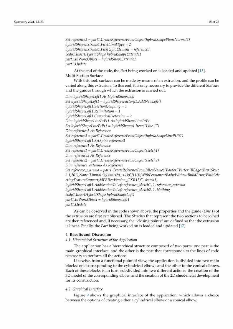
In order to create the sheet-metal development of the cylindrical elbow, and due tothe difficulty in programming Visual Basic directly in the CATIA “Drafting” module, the“Part Design” module has been used to first program the development of the elbow in aSketch and to later project it to the CATIA “Drafting” module. To this end, it is necessary toactivate the “Project 3D wireframe” option within the ‘Properties’ option.
The result of this operation is automatically displayed in a drawing (Figure 12).
4.2.2. Conical Elbow
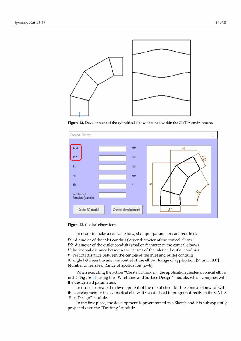
In the case of selecting the “Conical Elbow” option, the corresponding form will bedisplayed automatically (Figure 13). The interface is very similar to that of the CylindricalElbow and has the same elements in the form, but with an additional parameter, sincethere are two different diameters: the diameter of the inlet conduit (D1), and the diameterof the outlet conduit (D2).
Symmetry 2021, 13, 33 18 of 23
Symmetry 2021, 13, x FOR PEER REVIEW 18 of 24
In order to create the sheet-metal development of the cylindrical elbow, and due to the difficulty in programming Visual Basic directly in the CATIA “Drafting” module, the “Part Design” module has been used to first program the development of the elbow in a Sketch and to later project it to the CATIA “Drafting” module. To this end, it is necessary to activate the “Project 3D wireframe” option within the ‘Properties’ option.
The result of this operation is automatically displayed in a drawing (Figure 12).
Figure 12. Development of the cylindrical elbow obtained within the CATIA environment.
4.2.2. Conical Elbow In the case of selecting the “Conical Elbow” option, the corresponding form will be
displayed automatically (Figure 13). The interface is very similar to that of the Cylindrical Elbow and has the same elements in the form, but with an additional parameter, since there are two different diameters: the diameter of the inlet conduit (D1), and the diameter of the outlet conduit (D2).
Figure 13. Conical elbow form.
In order to make a conical elbow, six input parameters are required: 𝐷1: diameter of the inlet conduit (larger diameter of the conical elbow). 𝐷2: diameter of the outlet conduit (smaller diameter of the conical elbow).
Figure 12. Development of the cylindrical elbow obtained within the CATIA environment.
Symmetry 2021, 13, x FOR PEER REVIEW 18 of 24
In order to create the sheet-metal development of the cylindrical elbow, and due to the difficulty in programming Visual Basic directly in the CATIA “Drafting” module, the “Part Design” module has been used to first program the development of the elbow in a Sketch and to later project it to the CATIA “Drafting” module. To this end, it is necessary to activate the “Project 3D wireframe” option within the ‘Properties’ option.
The result of this operation is automatically displayed in a drawing (Figure 12).
Figure 12. Development of the cylindrical elbow obtained within the CATIA environment.
4.2.2. Conical Elbow In the case of selecting the “Conical Elbow” option, the corresponding form will be
displayed automatically (Figure 13). The interface is very similar to that of the Cylindrical Elbow and has the same elements in the form, but with an additional parameter, since there are two different diameters: the diameter of the inlet conduit (D1), and the diameter of the outlet conduit (D2).
Figure 13. Conical elbow form.
In order to make a conical elbow, six input parameters are required: 𝐷1: diameter of the inlet conduit (larger diameter of the conical elbow). 𝐷2: diameter of the outlet conduit (smaller diameter of the conical elbow).
Figure 13. Conical elbow form.
In order to make a conical elbow, six input parameters are required:
D1: diameter of the inlet conduit (larger diameter of the conical elbow).D2: diameter of the outlet conduit (smaller diameter of the conical elbow).H: horizontal distance between the centres of the inlet and outlet conduits.V: vertical distance between the centres of the inlet and outlet conduits.θ: angle between the inlet and outlet of the elbow. Range of application [5◦ and 180◦].Number of ferrules. Range of application [2−8].
When executing the action “Create 3D model”, the application creates a conical elbowin 3D (Figure 14) using the “Wireframe and Surface Design” module, which complies withthe designated parameters.
In order to create the development of the metal sheet for the conical elbow, as withthe development of the cylindrical elbow, it was decided to program directly in the CATIA“Part Design” module.
In the first place, the development is programmed in a Sketch and it is subsequentlyprojected onto the “Drafting” module.

Symmetry 2021, 13, 33 19 of 23
Symmetry 2021, 13, x FOR PEER REVIEW 19 of 24
𝐻: horizontal distance between the centres of the inlet and outlet conduits. 𝑉: vertical distance between the centres of the inlet and outlet conduits. θ: angle between the inlet and outlet of the elbow. Range of application [5° and 180°]. Number of ferrules. Range of application [2−8].
When executing the action “Create 3D model”, the application creates a conical el-bow in 3D (Figure 14) using the “Wireframe and Surface Design” module, which complies with the designated parameters.
Figure 14. 3D model of the conical elbow obtained within the CATIA environment.
In order to create the development of the metal sheet for the conical elbow, as with the development of the cylindrical elbow, it was decided to program directly in the CATIA “Part Design” module.
In the first place, the development is programmed in a Sketch and it is subsequently projected onto the “Drafting” module.
The result of this operation is automatically displayed in a drawing (Figure 15).
Figure 15. Development of the conical elbow obtained within the CATIA environment.
Figure 14. 3D model of the conical elbow obtained within the CATIA environment.
The result of this operation is automatically displayed in a drawing (Figure 15).
Symmetry 2021, 13, x FOR PEER REVIEW 19 of 24
𝐻: horizontal distance between the centres of the inlet and outlet conduits. 𝑉: vertical distance between the centres of the inlet and outlet conduits. θ: angle between the inlet and outlet of the elbow. Range of application [5° and 180°]. Number of ferrules. Range of application [2−8].
When executing the action “Create 3D model”, the application creates a conical el-bow in 3D (Figure 14) using the “Wireframe and Surface Design” module, which complies with the designated parameters.
Figure 14. 3D model of the conical elbow obtained within the CATIA environment.
In order to create the development of the metal sheet for the conical elbow, as with the development of the cylindrical elbow, it was decided to program directly in the CATIA “Part Design” module.
In the first place, the development is programmed in a Sketch and it is subsequently projected onto the “Drafting” module.
The result of this operation is automatically displayed in a drawing (Figure 15).
Figure 15. Development of the conical elbow obtained within the CATIA environment. Figure 15. Development of the conical elbow obtained within the CATIA environment.
4.3. Analysis of Possible Errors
Obviously, it is not possible to give any value to the input parameters, since, forexample, an elbow cannot be designed by introducing negative values in the diameterof the conduits. For this reason, it may be the case that when entering a value that liesoutside the range or some combination of values with which it is impossible to design theelbow, the application automatically displays an error message that indicates the reason.These errors are shown through a pop-up window that appears when any of the CommandButtons are pressed.
Therefore, a series of error warnings have been programmed in the internal code ofeach of the Command Buttons. These lines of code are placed immediately after the inputparameter designation code.
All the error messages programmed in the application are laid out below.

Symmetry 2021, 13, 33 20 of 23
4.3.1. Angle between the Inlet and Outlet Openings of the Elbow between 5◦ and 180◦
The input parameter (θ) represents the angle between the inlet and outlet openings ofthe elbow. This parameter has been programmed with a range of possible values between5 and 180 sexagesimal degrees.
It is considered that an elbow of more than 180◦ has little application in the metalfabrication sector, and that if it were necessary to design such an elbow, it could be built byjoining two elbows of smaller angles.
Elbows with an angle of less than 5◦ are not considered, since the two conduits couldbe joined by a single ferrule, with which their construction would be easier, and the pressureloss would not be much greater.
4.3.2. Number of Ferrules between 2 and 8
The parameter of the number of ferrules designates the number of parts that areemployed to build the elbow. In a metal fabrication elbow, the number of ferrules is definedby an integer number of parts, which has a minimum value of two ferrules and couldideally have an infinite number of ferrules (although this would not make sense).
The UNE-EN 10224 [21] standard states: angular elbows with an angle θ ≤ 30◦ mustbe built using two ferrules; elbows with an angle between 30◦ < θ ≤ 60◦, with three ferrules;and those with an angle between 60◦ < θ ≤ 90◦ must have four ferrules. Therefore, sincethe range of application of the elbow angle is defined up to 180◦, this parameter has beenprogrammed to have a range of application comprised between a minimum of two to amaximum of eight ferrules.
4.3.3. Diameter D1 Must Be Greater Than Diameter D2
As can be perceived, this error only has an effect in the case of the conical elbow, sincethis is the one that joins two conduits of different diameters.
The application has been programmed in such a way that diameter D1 will always bethe diameter corresponding to the opening with the largest diameter in the conical elbow.Therefore, if a value is entered in the input parameters that does not comply with the D1 >D2 relationship, then this error message is automatically displayed.
4.3.4. Unable to Create Elbow
Entering parameter values and trying to run a command may trigger the appearanceof an error message, since, with the set of values entered, it may be physically impossibleto construct a conical or cylindrical elbow.
There are several situations in which this error can occur.
Case 1
The dimension parameters of the diameters must be positive values. Obviously, theelbow cannot be constructed if any of these diameters has a negative value or is equal tozero. Therefore, the following relationship must be fulfilled:
D > 0 (cylindrical elbow) or D1 > 0; D2 > 0 (conical elbow)
Furthermore, the elbow will always be considered to develop towards the right. Inother words, the parameter of the horizontal distance is also always going to be greaterthan zero (H > 0). Specifically, it is programmed that if any of these variables is negative orequal to zero, then the error message is automatically displayed, and the Exit Sub commandis executed to exit the application. The code is shown below:
If CInt(D) <= 0 Or CInt(H) <= 0 Or CInt(V) <= 0 ThenMsgBox “Unable to create elbow”Exit SubEnd If

Symmetry 2021, 13, 33 21 of 23
Case 2
Another condition that must be met to design the elbow is that the lines of the axesof the inlet and outlet conduits have to intersect at a point with a positive Y coordinate(Figure 16).
Symmetry 2021, 13, x FOR PEER REVIEW 21 of 24
Case 1 The dimension parameters of the diameters must be positive values. Obviously, the
elbow cannot be constructed if any of these diameters has a negative value or is equal to zero. Therefore, the following relationship must be fulfilled: 𝐷 > 0 (cylindrical elbow) or 𝐷1 > 0; 𝐷2 > 0 (conical elbow)
Furthermore, the elbow will always be considered to develop towards the right. In other words, the parameter of the horizontal distance is also always going to be greater than zero (𝐻 > 0). Specifically, it is programmed that if any of these variables is negative or equal to zero, then the error message is automatically displayed, and the Exit Sub com-mand is executed to exit the application. The code is shown below: If CInt(D) <= 0 Or CInt(H) <= 0 Or CInt(V) <= 0 Then MsgBox “Unable to create elbow” Exit Sub End If Case 2
Another condition that must be met to design the elbow is that the lines of the axes of the inlet and outlet conduits have to intersect at a point with a positive Y coordinate (Figure 16).
(a) (b)
Figure 16. (a) Possibility of designing the elbow and (b) Impossibility of designing the elbow.
As can be observed in the case on the right, the intersection point of the two axes occurs below the first opening, which is the opening that marks the negative Y coordinate.
Making use of basic trigonometry and the parameters defined for the application, it can be deduced that the necessary relationship to fulfil this condition is: 𝑌 = 𝑉 − 𝐻tan 𝜃 > 0 (4)
where the variable Y is the value of the Y coordinate at the intersection point of the two axes. When programming, the same loop as in Case 1 is used. The only difference is the conditioner of the loop, that is, Equation (4). Case 3
In this case, the relative position between the inlet and outlet openings must be ful-filled (Figure 17), that is, point B must be located further to the right than point A.
Figure 16. (a) Possibility of designing the elbow and (b) Impossibility of designing the elbow.
As can be observed in the case on the right, the intersection point of the two axesoccurs below the first opening, which is the opening that marks the negative Y coordinate.
Making use of basic trigonometry and the parameters defined for the application, itcan be deduced that the necessary relationship to fulfil this condition is:
Y = V − Htan θ
> 0 (4)
where the variable Y is the value of the Y coordinate at the intersection point of the twoaxes. When programming, the same loop as in Case 1 is used. The only difference is theconditioner of the loop, that is, Equation (4).
Case 3
In this case, the relative position between the inlet and outlet openings must be fulfilled(Figure 17), that is, point B must be located further to the right than point A.
Symmetry 2021, 13, x FOR PEER REVIEW 22 of 24
(a) (b)
Figure 17. (a) Possibility of designing the elbow and (b) Impossibility of designing the elbow.
As in the previous case, in order to deduce the relationship that is required to fulfil this condition, it has been based on basic trigonometry and on the parameters defined. 𝐻 − 𝐷22 ∗ cos (𝜃) > 𝐷12 (5)
Thus, Equation (5) fulfils the condition that the X coordinate of point B must be greater than the X coordinate of point A. When programming, the same loop is used as in Case 1. The only difference is the conditioner of the loop, that is, Equation (5). Case 4
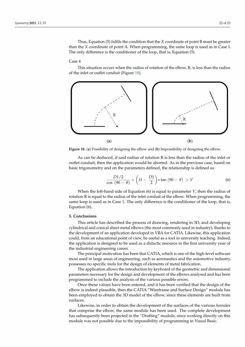
This situation occurs when the radius of rotation of the elbow, R, is less than the ra-dius of the inlet or outlet conduit (Figure 18).
(a) (b)
Figure 18. (a) Possibility of designing the elbow and (b) Impossibility of designing the elbow.
As can be deduced, if said radius of rotation R is less than the radius of the inlet or outlet conduit, then the application would be aborted. As in the previous case, based on basic trigonometry and on the parameters defined, the relationship is defined as: 𝐷1/2cos (90 − 𝜃) + 𝐻 − 𝐷12 ∗ tan (90 − 𝜃) > 𝑉 (6)
When the left-hand side of Equation (6) is equal to parameter V, then the radius of rotation R is equal to the radius of the inlet conduit of the elbow. When programming, the same loop is used as in Case 1. The only difference is the conditioner of the loop, that is, Equation (6).
Figure 17. (a) Possibility of designing the elbow and (b) Impossibility of designing the elbow.
As in the previous case, in order to deduce the relationship that is required to fulfilthis condition, it has been based on basic trigonometry and on the parameters defined.
H − D22∗ cos (θ) >
D12
(5)
Symmetry 2021, 13, 33 22 of 23
Thus, Equation (5) fulfils the condition that the X coordinate of point B must be greaterthan the X coordinate of point A. When programming, the same loop is used as in Case 1.The only difference is the conditioner of the loop, that is, Equation (5).
Case 4
This situation occurs when the radius of rotation of the elbow, R, is less than the radiusof the inlet or outlet conduit (Figure 18).
Symmetry 2021, 13, x FOR PEER REVIEW 22 of 24
(a) (b)
Figure 17. (a) Possibility of designing the elbow and (b) Impossibility of designing the elbow.
As in the previous case, in order to deduce the relationship that is required to fulfil this condition, it has been based on basic trigonometry and on the parameters defined. 𝐻 − 𝐷22 ∗ cos (𝜃) > 𝐷12 (5)
Thus, Equation (5) fulfils the condition that the X coordinate of point B must be greater than the X coordinate of point A. When programming, the same loop is used as in Case 1. The only difference is the conditioner of the loop, that is, Equation (5). Case 4
This situation occurs when the radius of rotation of the elbow, R, is less than the ra-dius of the inlet or outlet conduit (Figure 18).
(a) (b)
Figure 18. (a) Possibility of designing the elbow and (b) Impossibility of designing the elbow.
As can be deduced, if said radius of rotation R is less than the radius of the inlet or outlet conduit, then the application would be aborted. As in the previous case, based on basic trigonometry and on the parameters defined, the relationship is defined as: 𝐷1/2cos (90 − 𝜃) + 𝐻 − 𝐷12 ∗ tan (90 − 𝜃) > 𝑉 (6)
When the left-hand side of Equation (6) is equal to parameter V, then the radius of rotation R is equal to the radius of the inlet conduit of the elbow. When programming, the same loop is used as in Case 1. The only difference is the conditioner of the loop, that is, Equation (6).
Figure 18. (a) Possibility of designing the elbow and (b) Impossibility of designing the elbow.
As can be deduced, if said radius of rotation R is less than the radius of the inlet oroutlet conduit, then the application would be aborted. As in the previous case, based onbasic trigonometry and on the parameters defined, the relationship is defined as:
D1/2cos (90− θ)
+
(H − D1
2
)∗ tan (90− θ) > V (6)
When the left-hand side of Equation (6) is equal to parameter V, then the radius ofrotation R is equal to the radius of the inlet conduit of the elbow. When programming, thesame loop is used as in Case 1. The only difference is the conditioner of the loop, that is,Equation (6).
5. Conclusions
This article has described the process of drawing, rendering in 3D, and developingcylindrical and conical sheet-metal elbows (the most commonly used in industry), thanks tothe development of an application developed in VBA for CATIA. Likewise, this applicationcould, from an educational point of view, be useful as a tool in university teaching. Indeed,the application is designed to be used as a didactic resource in the first university year ofthe industrial engineering career.
The principal motivation has been that CATIA, which is one of the high-level softwaremost used in large areas of engineering, such as aeronautics and the automotive industry,possesses no specific tools for the design of elements of metal fabrication.
The application allows the introduction by keyboard of the geometric and dimensionalparameters necessary for the design and development of the elbows analysed and has beenprogrammed to include the analysis of the various possible errors.
Once these values have been entered, and it has been verified that the design of theelbow is indeed plausible, then the CATIA “Wireframe and Surface Design” module hasbeen employed to obtain the 3D model of the elbow, since these elements are built fromsurfaces.
Likewise, in order to obtain the development of the surfaces of the various ferrulesthat comprise the elbow, the same module has been used. The complete developmenthas subsequently been projected in the “Drafting” module, since working directly on thismodule was not possible due to the impossibility of programming in Visual Basic.

Symmetry 2021, 13, 33 23 of 23
As a continuation of this line of research, future lines of development arise for theimprovement and expansion of this application, such as the design and development ofhoppers and adapter surfaces.
Author Contributions: Conceptualisation, J.I.R.-S., G.d.R.-C., R.O.-M., and J.M.L.-P.; methodology,J.I.R.-S. and J.M.L.-P.; investigation, J.I.R.-S., G.d.R.-C., R.O.-M., and J.M.L.-P.; visualisation, J.I.R.-S.,G.d.R.-C., R.O.-M., and J.M.L.-P.; writing—original draft preparation, J.I.R.-S. and J.M.L.-P.; writing—review and editing, J.I.R.-S. and J.M.L.-P. All authors have read and agreed to the published versionof the manuscript.
Funding: This research has received no external funding.
Acknowledgments: The authors thank the anonymous reviewers, whose constructive commentshelped towards improving this paper.
Conflicts of Interest: The authors declare there to be no conflict of interest.
References1. Rojas-Sola, J.I.; Hernández-Díaz, D.; Villar-Ribera, R.; Hernández-Abad, V.; Hernández-Abad, F. Computer-Aided Sketching:
Incorporating the locus to improve the three-dimensional geometric design. Symmetry 2020, 12, 1181. [CrossRef]2. Rojas-Sola, J.I.; De la Morena-de la Fuente, E. The Hay inclined plane in Coalbrookdale (Shropshire, England): Geometric
modeling and virtual reconstruction. Symmetry 2019, 11, 589. [CrossRef]3. Rojas-Sola, J.I.; Galán-Moral, B.; De la Morena-de la Fuente, E. Agustín de Betancourt’s double-acting steam engine: Geometric
modeling and virtual reconstruction. Symmetry 2018, 10, 351. [CrossRef]4. Hu, G.; Bo, C.C.; Wu, J.L.; Wei, G.; Hu, F. Modeling of free-form complex curves using SG-Bezier curves with constraints of
geometric continuities. Symmetry 2018, 10, 545. [CrossRef]5. Escudero, I. Calderería; C.I.F.P.: Avilés, Oviedo, Spain, 2010. (In Spanish)6. Del Río-Cidoncha, G.; Martínez-Palacios, J.; Ortíz-Marin, R.; Rojas-Sola, J.I. Educational software to develop sheet metal with
Solid Edge. Comput. Appl. Eng. Educ. 2009, 17, 295–304. [CrossRef]7. Romeu, M.L.G.; De Ciurana, Q. Design and manufacturing assistance tool for drawing sheet metal parts. In Proceedings of the
1st International Conference on Cooperative Design, Visualization, and Engineering, Palma de Mallorca, Spain, 19–22 September2004; Springer: Berlin/Heidelberg, Germany, 2004; pp. 123–132.
8. Tang, M.; Zhang, Z.X.; Zhang, J.Q. Visual inspection of industrial sheet metal part with CAD data. In Proceedings of the Societyof Photo-Optical Instrumentation Engineers (SPIE), Wuhan, China, 15–17 November 2007; Volume 6788, p. K7880. [CrossRef]
9. Cavallini, B.; Puigpinos, L. New technology for the manufacture of sheet metal parts directly from CAD files. Virtual modelingand rapid manufacturing advanced research in virtual and rapid prototyping. In Proceedings of the 2nd International Conferenceon Advanced Research and Rapid Prototyping, Leire, Portugal, 28 September–1 October 2005; pp. 435–439.
10. Li, F.S.; Han, Z.S. Application of CAD/CAM technology in the development and lofting of complex sheet metal parts. InternationalConference on Mechatronics and Materials Processing (ICMMP 2011). Adv. Mater. Res. 2011, 328, 478–482. [CrossRef]
11. Neto, P. Off-line programming and simulation from CAD drawings: Robot-assisted sheet metal bending. In Proceedings of the39th Annual Conference of the IEEE Industrial Electronics Society, Vienna, Austria, 10–14 November 2013; pp. 4235–4240.
12. Martins, T.W.; Albrecht, K.; Anderl, R. Automated import of XML-files containing optimized geometric data to 3D-CAD modelsof non-linear integral bifurcated sheet metal parts. In Proceedings of the ASME International Design Engineering TechnicalConferences and Computers and Information in Engineering Conference, V01AT02A016, Boston, MA, USA, 2–5 August 2015.
13. Galileo Software. Available online: http://www.eng-pc.com/Caldereria.htm (accessed on 21 August 2020).14. Lantek Sheet Metal Solutions. Available online: https://www.lantek.com/es/caldereria-cad-cam-nesting-software (accessed on
21 August 2020).15. LogiTRACE. Available online: https://logitrace.programas-gratis.net (accessed on 21 August 2020).16. LITIO 2.0. Available online: http://www.litio.si/esp/li2index.htm (accessed on 21 August 2020).17. Plate’n’Sheet. Available online: http://www.sicam-info.com/pns.htm (accessed on 21 August 2020).18. Cobos-Gutiérrez, C.; Rodríguez-Domínguez, A.; Martín-Salinas, J. Geometría Para Ingenieros; Tebar: Madrid, Spain, 2001. (In Spanish)19. Díaz-Díaz, E. Tratado de Trazados y Desarrollos de Calderería; Marcombo: Barcelona, Spain, 2010. (In Spanish)20. Ross, E. VB Scripting for CATIA v5: How to Program CATIA Macros; Createspace Independent Pub: Scott Valley, CA, USA, 2012.21. UNE-EN 10224:2003/A1:2006e. Non-Alloy Steel Tubes and Fittings for the Conveyance of Water and Other Aqueous Liquids—Technical
Delivery Conditions; UNE: Madrid, Spain, 2006. (In Spanish)