Design and Development of a cyclonic device for Diesel Engine
21
Design and Development of a cyclonic device for Diesel Engine P. SYEDA NOORI BANU Department of Mechanical Engineering A.V.N. Institute of Engineering and Technology, Affiliated to Jawaharlal Nehru Technological University-Hyderabad (JNTUH) Paelguda,Ragannaguda, Koheda Road, Ibrahimpatnam Hyderabad, Andhra Pradesh, India Abstract Air pollution due to vehicular exhausts generate pollutants such as carbon dioxide, unburned hydrocarbons(UHC), oxide of nitrogen and lead and other particulate emissions. The level of pollutants prevalent in the atmosphere today is detrimental to the health of human population particularly children and those with affected with chronic diseases. Hence emission control devices have been developed by several researchers for simultaneous control of hydrocarbons (HC), carbon monoxide(CO), oxides of nitrogen(NOX) and particulate in automobile engine exhaust. In the current study, we have designed a cyclonic separator by optimizing conditions like collection efficiency, low pressure drop across the cyclone and vortex finder size and tested its efficacy in removing the particulate matter. Cyclone separator was found to be cheap and cost-effective strategy to minimize air and sound pollution. Key words: carbon dioxide(CO2) unburned hydrocarbons(UHC); hydrocarbons(HC); carbon monoxide(CO); oxides of nitrogen(NOX); polycyclic aromatic compounds (PAC). 1.Introduction There are about thousand chemicals in the motor vehicle exhaust. We are yet to find out the effects of many of these. The main pollutant from internal combustion engines are carbon dioxide, unburned hydrocarbons(UHC), oxides of nitrogen and lead and other particulate emissions [Haagen-Smit (1952)]. These particulate emissions contribute substantially to already high levels of total suspended particals in urban areas. Diesel particulates are also considered as potential health hazard, mainly because of the polycyclic aromatic compound (PAC) present in the solvent fraction of the particulates. Some of the PACs are known to be carcinogenic. These particulates also cause irritability, restlessness, depression, anxiety etc. These particulates settle down on buildings and trees etc [Valavanidis et al (2008)]. The prosperity of a country is dependent upon the efficient and rational use of energy use of energy, which is necessary for industry and transportation. It also plays an important role in one’s life. A flexible energy policy is therefore necessary and this utilizes two coupled objectives that is improving energy efficiency in cost effective way and reducing environmental pollution. The level of pollutants prevalent into atmosphere today is detrimental to the health of population particularly children and those in different health. Hence emission control devices have been developed by several researchers for simultaneous control of hydrocarbons (HC), carbon monoxide (CO), oxides of nitrogen (NOX) and particulate engine exhaust. Among them cyclonic separator is an effective method to reduce particulate emissions to very low levels. 1.1 Pollutant formation in diesel engines In diesel engine, the fuel is injected into the cylinder just before the combustion starts. So throughout most of the critical parts of the cycle, the fuel distribution is non uniform. The pollutant formation processes are strongly dependent on the fuel distribution changes with time. Due to mixing, various parts of the fuel jet and flame affect the formation of NO, unburned hydrocarbons and soot. During the premixed and mixing controlled phases of diesel combustion in a direct injection engine with swirl, nitric oxide forms in the high temperature regions but temperature and air fuel ratio distributions with in the burned gases are non uniform and formation rates are highest in the close to stoichiometric regions. Soot forms in the rich unburned- fuel- containing- core of the fuel sprays with in flame region, where the fuel vapor is heated by mixing with hot burned gases. Soot then oxidizes P. Syeda Noori Banu / International Journal of Engineering Science and Technology (IJEST) ISSN : 0975-5462 Vol. 3 No. 4 Apr 2011 3283
Transcript of Design and Development of a cyclonic device for Diesel Engine

Design and Development of a cyclonic device for Diesel Engine
P. SYEDA NOORI BANU
Department of Mechanical Engineering A.V.N. Institute of Engineering and Technology,
Affiliated to Jawaharlal Nehru Technological University-Hyderabad (JNTUH) Paelguda,Ragannaguda, Koheda Road, Ibrahimpatnam
Hyderabad, Andhra Pradesh, India
Abstract Air pollution due to vehicular exhausts generate pollutants such as carbon dioxide, unburned hydrocarbons(UHC), oxide of nitrogen and lead and other particulate emissions. The level of pollutants prevalent in the atmosphere today is detrimental to the health of human population particularly children and those with affected with chronic diseases. Hence emission control devices have been developed by several researchers for simultaneous control of hydrocarbons (HC), carbon monoxide(CO), oxides of nitrogen(NOX) and particulate in automobile engine exhaust. In the current study, we have designed a cyclonic separator by optimizing conditions like collection efficiency, low pressure drop across the cyclone and vortex finder size and tested its efficacy in removing the particulate matter. Cyclone separator was found to be cheap and cost-effective strategy to minimize air and sound pollution. Key words: carbon dioxide(CO2) unburned hydrocarbons(UHC); hydrocarbons(HC); carbon monoxide(CO); oxides of nitrogen(NOX); polycyclic aromatic compounds (PAC). 1.Introduction
There are about thousand chemicals in the motor vehicle exhaust. We are yet to find out the effects of many of these. The main pollutant from internal combustion engines are carbon dioxide, unburned hydrocarbons(UHC), oxides of nitrogen and lead and other particulate emissions [Haagen-Smit (1952)]. These particulate emissions contribute substantially to already high levels of total suspended particals in urban areas. Diesel particulates are also considered as potential health hazard, mainly because of the polycyclic aromatic compound (PAC) present in the solvent fraction of the particulates. Some of the PACs are known to be carcinogenic. These particulates also cause irritability, restlessness, depression, anxiety etc. These particulates settle down on buildings and trees etc [Valavanidis et al (2008)]. The prosperity of a country is dependent upon the efficient and rational use of energy use of energy, which is necessary for industry and transportation. It also plays an important role in one’s life. A flexible energy policy is therefore necessary and this utilizes two coupled objectives that is improving energy efficiency in cost effective way and reducing environmental pollution. The level of pollutants prevalent into atmosphere today is detrimental to the health of population particularly children and those in different health. Hence emission control devices have been developed by several researchers for simultaneous control of hydrocarbons (HC), carbon monoxide (CO), oxides of nitrogen (NOX) and particulate engine exhaust. Among them cyclonic separator is an effective method to reduce particulate emissions to very low levels. 1.1 Pollutant formation in diesel engines
In diesel engine, the fuel is injected into the cylinder just before the combustion starts. So throughout most of the critical parts of the cycle, the fuel distribution is non uniform. The pollutant formation processes are strongly dependent on the fuel distribution changes with time. Due to mixing, various parts of the fuel jet and flame affect the formation of NO, unburned hydrocarbons and soot. During the premixed and mixing controlled phases of diesel combustion in a direct injection engine with swirl, nitric oxide forms in the high temperature regions but temperature and air fuel ratio distributions with in the burned gases are non uniform and formation rates are highest in the close to stoichiometric regions. Soot forms in the rich unburned- fuel- containing- core of the fuel sprays with in flame region, where the fuel vapor is heated by mixing with hot burned gases. Soot then oxidizes
P. Syeda Noori Banu / International Journal of Engineering Science and Technology (IJEST)
ISSN : 0975-5462 Vol. 3 No. 4 Apr 2011 3283

in the flame zone when it contacts unburned oxygen giving rise the yellow luminous character of the flame. Hydrocarbons and aldehydes originate in regions where flame quenches both on the walls and where excessive dilution with air prevents the combustion process from either starting or going to completion. Fuel that vaporizes from the nozzle sac volume during the later stages of combustion is also a source of HC. Combustion generated noise is controlled by the early part of the combustion process, the initial rapid heat release immediately following the ignition delay period [Kennedy, 1997]. 1.2 Diesel particulate – types Different types of particulates are emitted from dieses engines under different modes and operating conditions. These particulates can be divided into three types.
1. Liquid particulates appear as white/blue clouds of vapor emitted under cold starting idling and low loads.
2. Soot or Black smoke particulates are emitted as a product of incomplete combustion process particularly maximum loads.
3. Other particulates include lubricating and fuel additives. The present work is limited to soot particulates.
1.3 Diesel particulate formation The soot particulates form primarily from carbon in the diesel fuel. The formation process starts with the molecules containing 12 to 22 carbon atoms and a hydrogen and carbon ratio of about 2, and ends up with particles typically a few hundred nanometers in diameter, composed of spherules 20 to 30 nanometers in diameter each containing about 100000 are two separate stages for the production of diesel particulates.
1. Particle generation: Here, the first condensed phase material arises from the fuel molecules via their oxidation and/ or pyrolysis products. These products typically include various unsaturated hydrocarbons particularly acetylene and its higher analogues and polycyclic aromatic hydrocarbons (PAH). These first particles are very small and often called nuclei.
2. Particle growth: Particle growth includes surface growth, coagulation and aggregation. During surface
growth condensation of species with the right hydrogen content or condensation of species with higher hydrogen content followed by dehydrogenation or a combination of both these processes take place. During coagulation particles collide coalesce. Once surface growth stops, continued aggregation of particles into chains and clusters can occur. At each stage in the above process oxidation can occur. The eventual emission of particulates from the engine will depend on the balance between these processes of formation and burnout.
1.4 Particulate emission control Particulate emission control may be carried out either in the formation stage or with an add-on device in the exhaust system. Control in the formation stage may be affected by optimization of combustion system and fuel injection system. Fuels can have an effect on particulate emission with high end boiling point fuels giving higher particulate emissions. Advancing the start of injection reduce the particulate intensity however it results in more combustion noise, thermal stresses and higher number of emissions. It is also found that very late injection reduce particulate intensity. Higher initial rates of injection reduce particulates.
(a) Thermal in stream oxidation Since the exhaust always contains some oxygen, the diesel particulates can be eliminated by oxidation if temperature is high enough and time for burning long enough. Raising the particle temperature by heating the bulk of exhaust gas requires a large amount of energy. A heat exchanger operating at temperature of about 12000C would be required for this purpose. Design of compact heat exchanger for this temperature and flow rates involved would be difficult [Ladommatos and Zhao (1994)].
P. Syeda Noori Banu / International Journal of Engineering Science and Technology (IJEST)
ISSN : 0975-5462 Vol. 3 No. 4 Apr 2011 3284
(b) Catalytic stream oxidation
One way to speed up the burning rate of diesel particulates at exhaust temperature is to use a suitable catalyst [Barnes (1975)]. The catalyst is an additive to the diesel fuel. Such a catalyst of- course have to be incorporated in the particle as it is formed. A number of metals catalyze the activity for the oxidation of particulates. Barium, sodium, gold, copper, lead are some examples. Some of these metals would have toxicity problems and some are costly. (c)Trap Oxidizers
Basic problem with the particulate in the diesel exhaust stream is that it is too dilute to burn. This can be remedied by collecting the material on a temperature tolerant filter or trap. Although a filter is thought of as a way to remove particulates from the flow stream, it can also be thought of as a device for concentrating the particulate matter. So oxidizing the accumulated particles is easy. Types of particulate filters include ceramic monoliths, aluminum coated wire mesh, ceramic foam, ceramic fiber mat, woven silica fiber rope wound on a porous tube. Each of this has different inherent pressure loss and filtering efficiency. Regeneration of the trap by burning up the filtered particulate matter can accomplished by raising its temperature to the ignition point while providing oxygen containing exhaust gas to support combustion and to carry away the heat released. This technology is difficult to implement because the filter even when clean increase the pressure in exhaust system. This pressure increase steadily rises as the filter collects particulate matter. More over under normal diesel engine operating conditions, the collected particulate matter will not ignite and oxidize. Once ignition of particulates occurs the burn up process must be carefully controlled to prevent excessively high temperature and trap damage or destruction [Feutlinske (1989), Holman (1990)]. (d) Cyclonic Separator
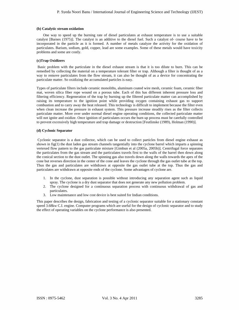
Cyclonic separator is a dust collector, which can be used to collect particles from diesel engine exhaust as shown in fig(1) the dust laden gas stream channels tangentially into the cyclone barrel which imparts a spinning vertexed flow pattern to the gas particulate mixture [Gimbun et al (2005a, 2005b)]. Centrifugal force separates the particulates from the gas stream and the particulates travels first to the walls of the barrel then down along the conical section to the dust outlet. The spinning gas also travels down along the walls towards the apex of the cone but reverses direction in the center of the cone and leaves the cyclone through the gas outlet tube at the top. Thus the gas and particulates are withdrawn at opposite the gas outlet tube at the top. Thus the gas and particulates are withdrawn at opposite ends of the cyclone. Some advantages of cyclone are.
1. In the cyclone, dust separation is possible without introducing any separation agent such as liquid spray. The cyclone is a dry dust separator that does not generate any new pollution problem.
2. The cyclone designed for a continuous separation process with continuous withdrawal of gas and particulates.
3. Low maintenance and low cost device is best suited for Indian conditions.
This paper describes the design, fabrication and testing of a cyclonic separator suitable for a stationary constant speed 3.68kw C.I. engine. Computer programs which are useful for the design of cyclonic separator and to study the effect of operating variables on the cyclone performance is also presented.
P. Syeda Noori Banu / International Journal of Engineering Science and Technology (IJEST)
ISSN : 0975-5462 Vol. 3 No. 4 Apr 2011 3285
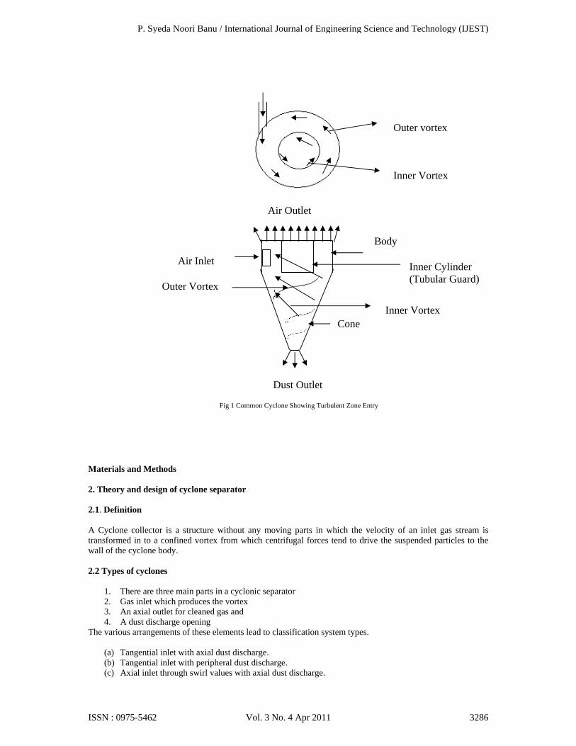
Materials and Methods 2. Theory and design of cyclone separator 2.1. Definition A Cyclone collector is a structure without any moving parts in which the velocity of an inlet gas stream is transformed in to a confined vortex from which centrifugal forces tend to drive the suspended particles to the wall of the cyclone body. 2.2 Types of cyclones
1. There are three main parts in a cyclonic separator 2. Gas inlet which produces the vortex 3. An axial outlet for cleaned gas and 4. A dust discharge opening
The various arrangements of these elements lead to classification system types.
(a) Tangential inlet with axial dust discharge. (b) Tangential inlet with peripheral dust discharge. (c) Axial inlet through swirl values with axial dust discharge.
Inner Cylinder (Tubular Guard)
Cone
Air Inlet
Dust Outlet
Air Outlet
Body
Outer Vortex
Inner Vortex
Outer vortex
Inner Vortex
Fig 1 Common Cyclone Showing Turbulent Zone Entry
P. Syeda Noori Banu / International Journal of Engineering Science and Technology (IJEST)
ISSN : 0975-5462 Vol. 3 No. 4 Apr 2011 3286

(d) Axial inlet through swirl values, with peripheral dust discharge The most commonly used cyclonic separator is tangential inlet with axial discharge. 2.3 Mechanism of cyclone operation
(a) Gas Flow patterns An understanding of gas flow patterns in the cyclone is necessary to assess factors that contribute to particle motion. The dominant flow pattern is one of an outer vortex core maintaining the same direction of rotation, travelling upward to the gas outlet. Cyclone flow patterns are best described in terms of three velocity components. TerLinden’s measurements of tangential, radial and axial gas velocities are shown in fig (2). Tangential gas velocity, gas entering the cyclone forms a confined vortex in which the tangential velocity ct (m/s) is related to the distance from the cyclone axis r (m) by Ct X r n= constant (1) Where n is constant called the vortex exponent. In the outer vortex, tangential velocity increase frame a minimum near the wall to higher value at t edge of the vortex core. For clean gas the vortex exponent (n) ranges from 0.5 to 0.9. From the edge of the vertex core to the cyclone axis tangential velocity decreases, and with in the core the gas rotates more nearly as a solid body. With ‘n’ closer to ‘-1’. Radial gas velocity: A gas spirals down the outside of the cyclone, it is continuously drawn of into vortex core. Although this radial component of gas velocity is relatively small and difficult to measure, it greatly affects the penetration of particles. Ter Linden’s measurements indicate a relatively constant inward radial velocity in the outer vortex at all vertical positions below the gas outlet duct. However, Rerznik and Mostsnev [Rerznik and Mostsnev (1971)] found that radial gas velocities just below the gas outlet were approximately 10times higher than radial velocities near the dust outlet. They estimated that higher velocities below the gas outlet were responsible for carrying out 85% of the dust that penetrated the cyclone. Axial gas velocity Gas within the cyclone flows down along the walls, conveying collected dust to the dust outlet. Fig 2 indicates that the transition in axial velocity from down to up occurs outside the central core.
(b) Separation of dust in the vortex Particulate matter is separated from the gas by centrifugal force which drives the particles towards the cyclone wall across the stream lines of the gas flow. The radial force imparted to the particle is Fs = mp X cp
2 (2) R Fs = Separating force in Newton’s mp = Particle mass in Kg. cp = Particle tangential velocity m/s R= Radius of rotation meters By assuming that particle velocity is the same as the gas velocity in the tangential direction cp becomes, Ct (R)n =constant= Ctp(R)n (3)
P. Syeda Noori Banu / International Journal of Engineering Science and Technology (IJEST)
ISSN : 0975-5462 Vol. 3 No. 4 Apr 2011 3287

Where Ctp = Tangential velocity at perimeter RP = Radius of cyclone body Ct = (RP)n ⁄ R (4) Cp = Ct = Ctp (Rp)
n / R (5) Introducing the parameters for particle mass the separating force (Fs) becomes β x ρp x d3x Ctp
2xRp2n
Fs= (6) R(2n+1) ρp= Particle density d= Particle diameter β = Volume shape factor (dimensionless) It can be shown that the strokes law force resisting the motion of a particle through the gas in the particle- size range 3-100 μm is Ft = K x μ x d x u (7) Ft= Frictional resistance to flow K= proportionality constant (dimensionless) μ= gas viscosity N/ms u= Particle velocity with respect to gas Thus the separating force increases with the cube of the particle diameter but the resistance to particle flow towards the cyclone wall increases only linearly with the particle diameter. In any practical cyclone the particulate matter is spread over the width of the dirty gas inlet, so that the radius of rotation, tangential velocity and distance from the cyclone wall vary from the layer entering next to the outer wall of the cyclone to the nearest the wall of the gas outlet. Therefore, cyclone separator does not make a sharp size cut between particles separated and passed Lapple (11) presented an equation typical of those supported to permit calculation of the particle size which will be collected in a given cyclone. (c) Discharge of separated dust The application of centrifugal force to drive particles out of the gas stream towards the w alls of the cyclone collector results in a concentrated dust layer swirling slowly down the walls of the cyclone separator body. The dust is yet to be finally separated from the gas stream. The purpose of discharge is to retain the dust in a container and to prevent its re-entertainment into the gas stream at the base of vortex. The length and dimension ratios of the cyclone body and cone of –course, affect re-entertainment Smoothness of the inner walls of the cyclone is essential to prevent small eddy currents which would bounce the dust layer out into the active zone of vortex. In leaking of gas into the dust outlet will be harmful to attempts to discharge the dust without re-entertainment. Conversely a small purge flow of gas outward from the dust outlet will be helpful. 2.4 Design features The primary design features necessary for cyclonic separator to function effectively are
(a) It should have relatively high collection efficiency. (b) Low pressure drops so that engine performance will not be adversely affected.
In addition to primary design considerations equally important secondary design factors are:
(a) It should be sufficiently compact to fit into small spaces available in passenger car (b) And truck exhaust systems (c) It must be able to withstand the high temperature and highly corrosive environment of the diesel engine
exhaust.
P. Syeda Noori Banu / International Journal of Engineering Science and Technology (IJEST)
ISSN : 0975-5462 Vol. 3 No. 4 Apr 2011 3288

(d) Other design factors which must be considered are manufacturing feasibility for production package feasibility etc.,
(e) It must be relatively inexpensive. The various cyclone dust collector designs can be grouped into two broad categories-
1. Axial gas entry 2. Tangential gas entry
The axial gas entry cyclone is best constructed by using castings for both the inlet vanes and the tubes. Hence, the axial- entry design is commercially available in few diameters, because casting patterns are costly to design, make and maintain. In addition, several hundred vanes and tubes are cast per run and inventories must be limited. This results also in a limitation of materials of construction. For all practical purposes, most manufactures limit their stock to two or three diameters and only one or two alloys. Another factor that should be kept in mind is that axial-entry cyclones are limited to ducts that can be handled without undue wear or danger of plugging the required inlet vanes. Axial entry cyclones have a gas capacity about twice that of wraparound entry cyclones of the same diameter. The tangential entry is best produced by using fabricated plate. Fabricated- plate cyclones can be manufactured in every size and shape and lend themselves well to application of internal refractory linings. Thus, the materials of construction required for the application will have a decisive influence on the design selected. The shape of the inlet will have influence both on the pressure drop and dust collection characteristics of the cyclone. 2.5 Material for cyclonic separator In reviewing the various processes, we will find that the material of construction must be selected not only for normal operation but with special attention paid to start up, shut down, or where there is a process upset or other emergency situation. The most critical factor in start up and shut down of the process is the possibility of moisture condensation on the internal surfaces of the cyclones condensation will invariably start corrosion and initiate dust agglomeration and build up. Cyclones can be constructed of any material which will meet the temperature and pressure requirements and corrosion potential of the carrier gas stream. Normally mild carbon steel is the first choice for low cost and reasonable life to overcome the action of corrosive particles. Harder metals such as abrasion resistant steel also can be used. Such cyclones are naturally more costly. Carbon steel has a gas- temperature limit of about 8000F. For higher temperatures, it is possible to use various stainless steel or other alloys. As an alternative to special alloys a very common approach is the use of carbon- steel cyclones provided with internal refractory liners. Materials often used to prevent dust from contamination are the various grades of stainless steels, aluminum, alloy steels, carbon etc. 2.6 Design procedure of cyclonic separator The important features to be considered in the design of cyclonic separator are (1) Collection efficiency of separator. (2) Pressure drop in the cyclonic separator. Remaining design variables are generally related to these factors.
2.6.1 Collection efficiency The inlet width of the cyclonic is first determined from the Lapple empirical expression for the collection efficiency of a cyclonic separator. This efficiency expression is based on the particle size for which collection efficiency is 0.5, designed here as ‘d.5’ and referred to as ‘particle cut size’. Lapple expression d.5 is d.5= 9μeB ½ (8) 2ПNsC ρp
P. Syeda Noori Banu / International Journal of Engineering Science and Technology (IJEST)
ISSN : 0975-5462 Vol. 3 No. 4 Apr 2011 3289

Where μ = dynamic viscosity of exhaust gas (N-s/m2) B = Inlet width (m) Ns = Effective number of turns made by gas stream in cyclone C= Cyclone inlet velocity ρp = density of particulate present in the exhaust
If number of cyclones used is one, Ve= C xA (9) = C x B x H1 (10) Where A = Cyclone inlet area H1 = Height of cyclone inlet Ve= Volume flow rate of exhaust gas Substituting equation 10 in equation 8 d.5= 9μeB 2 H1
½ 2ПNsVe ρp (11) Assuming inlet height (H1) is twice the inlet width (B) of the cyclone equation 11. Can be written as B = d.5
2x 2x ПxNsxVex ρp 1/3
9xμex 2 (12) Assuming a suitable value of d5 (depending on the application of cyclonic separator) inlet width (B) of the cyclone can be calculated using equation 12. In equation 12 values of Ve and μe has to be found out as described below.
Calculation of the volume flow rate of exhaust gas (Ve).
Volume flow rate of exhaust gas increase with in load. Finding volume flow rate of exhaust gas at full load involves the following steps. Volume flow rate of air entering the engine can be determined by using an orifice. Va= Cd A (2gh)1/2 (13)
Where Cd = Coefficient of discharge A= Area of orifice (Cross- section) H= Pressure difference across the orifice in meters of air column Density of air can be calculated using ideal gas law. ρ1= P1/ (Rx T1) (14) P1= Suction pressure T1= Suction temperature The mass flow rate of exhaust gas (mf)
P. Syeda Noori Banu / International Journal of Engineering Science and Technology (IJEST)
ISSN : 0975-5462 Vol. 3 No. 4 Apr 2011 3290

Mf= ρ1x Va+ ρf x Vf (15) Where, ρf = Density of fuel Vf = Volume flow rate of fuel The density of the exhaust gas (ρ2) can be calculated using ideal gas law. ρ2 = P2/(RxT2) (16) Where, P2= Exhaust pressure at full load T2= Exhaust temperature (K) at full load. If, Manometric Reading =X cm of water column Maximum load= Y kg(f) Time taken for 10cc of fuel consumption =Z sec. Speed, N = P rpm Room temperature= RT
0C Then, head of air column = (Xx1000) / (ρax100) =h meters of air (17) Mass flow through orifice= ρa60x CdA (2gh)1/2 kg/min (18) Fuel consumption F.C= (10x1000xSp. Gravity of Fuel x 3600) / (106xZ) (19) Hence the volume flow rate of exhaust gas Ve= mf/ ρ2 (20) (b) The dynamic viscosity of exhaust gas (μe) can be calculated using following relationship (10) μe= μair/( 1+ 0.0027Ø) (21)
Where, Ø= equivalent ratio μair=dynamic viscosity of air=3.3x10⁻⁷XT2
0.7 (22) All the other dimensions of a cyclone are based on this inlet width (B). The standard design proportions are given in Table 2.1 as dimensionless ratios based on the cyclone diameter Dc. 2.6.2Calculations of pressure drop The pressure drop in the cyclone can be calculated using the empirical relationship given by Sheppardand Lapple (19) P= (0.00513x ρ2C
2x KxBx H1)/ De2 cm of water (23)
P= (0.4931x ρ2C
2x KxBx H1)/ De2 N/m2 (24)
Where, De= Outlet diameter of the cyclone K= Constant having a value described below. With the normal arrangement in which the rectangular angular inlet terminates at the outer elements of the cyclone body ‘K’ was found to have a value of 16.0. If the inlet duct was extended past the cyclone cylinder wall and into the angular space half way to the opposite wall to form an inlet vane ‘K’ was found to have a value of 7.5. If the calculated pressure drop is higher (for this required application) one should select large cut particle size (d.5) and then calculated the pressure drop again. 2.7 Design of cyclonic separator for the present work
P. Syeda Noori Banu / International Journal of Engineering Science and Technology (IJEST)
ISSN : 0975-5462 Vol. 3 No. 4 Apr 2011 3291

Cyclonic proportions given by Lapple( Table 2.1) are selected for the present design. (a) Calculation of cyclonic dimensions assuming a particle cut size of 3μm. Volume flow rate of exhaust gas was found using equations 13, 14, 15, 16, 20. Technical data: Engine 3.68kw water cooled Kirloskar Diesel Engine. Number of cylinders 1, Speed 1500rpm, Stroke 110mm, Bore 80mm, Coefficient of discharge (Cd) 0.6, Cooling water cooling, Orifice diameter 24mm, Belt thickness 6mm, Brake drum diameter 31cm. Theoretical maximum load= 14.833 kg(f) Using equation 13 Cd= 0.6 A= П(0.024)2/4=0.000452m2
Using equation 14 P1=1 bar=1.01325x 10⁵ Pa R= 287 j/Kg-K. T1= 301K ρ1 = 101325/(287x301)= 1.1729 kg/m3 From equation 17 h = (2.6x1000)/ (1.1729x100)= 22.167m of air Air flow through orifice= Cd A (2gh) ½ = 0.6x 0.000452 (2x9.81x22.167)1/2 = 0.00oo4m3/sec Mass flow through orifice, ma =1.1729x60x0.6x0.000452 (2x9.81x22.167)1/2
= 0.39836Kg/min Using equation 15 The mass rate of exhaust gas (m) = ma + mf ma= mass of air = 0.39836, mf= mass of fuel = 0.6849/60 = 0.011415 kg/min m=0.39836 + (0.6849/60) = 0.4098 kg/min Using equation 16 Temperature of the exhaust gas T2 = 2900C = 563K ρe = Density of flue gas at 2900C= 0.6563 Kg/m3 (from heat transfer data book) Volume flow rate of exhaust gas Ve = m/ ρe = 0.4098/ 0.6563 = 0.624441 m3/min (b) Dynamic viscosity of exhaust of gas was found using equations 21, 22
P. Syeda Noori Banu / International Journal of Engineering Science and Technology (IJEST)
ISSN : 0975-5462 Vol. 3 No. 4 Apr 2011 3292

Using equation 21 μe = μair (1+0.027Ø) μair = 3.3x 10⁻⁷xT2
0.7 = 3.3 x 10-7x563 0.7 = 2.779x10⁻⁵ Pa-s where Ø= equivalence ratio =0.8 hence μe = 2.72x 10⁻⁵ Pa.s Cyclonic inlet width (B) can be calculated using equation (12) Assuming the particle density 2000Kg/m3 and number of spirals made by the gas in the cyclone as 6 Inlet width (B) = ( d.5
22ПNsVeρp) 1/3
9μe
2 1/3 = (3x10⁻⁶)2x2Пx6x0.62441x2000 9x2.72x10-5x2x60 = 0.02435m Using equation 9 Cyclone Inlet velocity, C C= Ve/ (2xB2) = 0.62441 60x2x (0.02435)2
= 8.775m/sec Body diameter of Cyclone = 4xB =4x 0.02435= 0.0974m Other dimensions of the cyclone are found using the proportions given in table 1 Body diameter of cyclone= Dc= 0.0974m Inlet Height = H1= 0.0487m Outlet length = H4= 0.0609m Out diameter = De= 0.0487m Cylinder Height = H2 = 0.1948m Cone Height = H3= 0.1948m Bottom diameter= Db = 0.02435m Dp = 0.4931ρ2C
2 KBH1 De
2 = 0.4931x0.6563x0.6563x8.7752x7.5x0.02435x0.0487 0.04872 =93.44N/m2 As this pressure drop is with in the reasonable limit. Therefore assumption of 3μm cut particle size is acceptable.
P. Syeda Noori Banu / International Journal of Engineering Science and Technology (IJEST)
ISSN : 0975-5462 Vol. 3 No. 4 Apr 2011 3293

Table 1. Standard design proportions
Symbol Nomenclature Recommended Authors
Lapple Swift Stairmand
1. Dc Body diameter 1.0 1.0 1.0 2 H1 Inlet height 0.5 0.44 0.5 3 B Inlet width 0.25 0.21 0.2 4 H4 Outer length 0.625 0.5 0.4 5 De Outer diameter 0.5 0.4 0.5 6 H2 Cylinder height 2.0 1.4 1.5 7 H3 Cone height 2.0 2.5 2.5 8 Db Bottom diameter 0.25 0.4 0.374 3. Experimental study of cyclonic separator 3.1 Introduction Testing the performance of the cyclone as an effective device to trap particulate matter involves the determination of the trapping efficiency of the cyclone is given by η = m1/m2
m1 =Mass of particulates with separator m2 = Mass of particulates without separator
196
49
98
196
Particulate
24.5
61
Exhaust gas with Particulate
Fig 2. Dimensions Of The Cyclone Designed
All Dimensions in mm
Clean Gas
P. Syeda Noori Banu / International Journal of Engineering Science and Technology (IJEST)
ISSN : 0975-5462 Vol. 3 No. 4 Apr 2011 3294

In the study and performance of a cyclonic separator experimentally the following measurements have been done.
(1) Weight of particulates in exhaust gas entering and leaving the cyclonic separator. (2) Fuel consumption with and without the separator. (3) Load on the engine (4) Brake thermal efficiency of the engine with and without cyclonic separator. (5) Exhaust gas temperature with and without cyclonic separator.
3.2 Measurement of particulate Mass Techniques generally used for particulate measurement and characterization are:
(1) Smoke meter method (2) Dilution Tunnel method (3) Solvent scrubbing system (4) Impinger method
These techniques require lengthy sample collection periods because the emission of particulate is usually low (1) Smoke meter method Smoke meter measures the relative quantity of light that passes through the exhaust or the relative reflectance of particulate collected on filter paper. They do not measure mass directly. They are used to determine visible smoke emission and provide an approximate indication of mass emission levels. (2)Dilution Tunnels Method Dilution tunnels are used to simulate the physical and chemical processes the particulate emissions undergo in atmosphere. In the dilution tunnel, the raw exhaust gases are diluted with ambient air to a temperature of 520C or less and a sample stream from the diluted exhausted is filtered to remove particulate matter. (3)Solvent Scrubbing System Recently solvent scrubbing exhaust sampling system has been used to measure particulates. Here exhaust products are fed into the base of a stainless steel tower and as they pass upward through the tower they are scrubbed by a downward flow of solvent (mixture of di chloromethane and methanol). Then the solvent is analyzed to measure the concentration of particulates. (4)Impinger method In this method, particulate are collected in liquid medium such as water. The exhaust gases are passed through collecting vessel which contains water. The exhaust pipe should be immersed below the surface of water. Exhaust gas bubbles though water and escapes. The particulate matter gets separated and retained in water. A well mixed sample of this water is filtered through a weighed standard filter paper and the residue retained on the filter is dried at 103 to 1050 to remove all the moisture content. The increase in weight of the filter paper represents the mass of total suspended particulates. In the present experimental study, this method has been employed to collect particulates and to determine its mass without separator. 3.3 Experimental set up The present experimental set up for testing the Cyclonic separator is shown schematically in Fig 3 and photographically in Fig 4 The primary air flow rate was measured by an orifice meter. The air to the engine was supplied through air tank. The temperature of the exhaust gas was measured by a thermocouple. The load on engine was measured by a Belt brake dynamometer.
P. Syeda Noori Banu / International Journal of Engineering Science and Technology (IJEST)
ISSN : 0975-5462 Vol. 3 No. 4 Apr 2011 3295

The speed of the engine was measured by a Tachometer. The details of the engine used in the present experimental set up are as follows. Four-Stroke, single cylinder, water cooled, constant speed, compression ignition kirloskar engine was used. Bore = 80mm, Stroke = 110mm, Speed = 1500rpm, Rated Power = 3.68kw. 3.4Experimental procedure The engine was started and allowed to run for 15minutes to attain steady conditions. The speed of the engine was maintained at 1500rpm. Fuel consumption and exhaust gas temperature on the engine were measured. The particulate collecting vessel was filled with sufficient water so that the exhaust gas leaving the pipe bubbles through the water. The following data were recorded during sampling period.
(1) Time of collection (2) The total volume of water and particulates in vessel The contents of the collecting vessel for each load were separately preserved for analysis later. The same procedure was repeated for different for different loads. To determine the particulate mass a well mixed sample of 200ml of the contents of the collecting vessel collected during each load was taken and filtered using a standard filtering apparatus. After filtering the filter paper along with the particulates is carefully transferred to an oven maintained at a temperature of 103+_0C. After during for about an hour, the filter paper along with the particulates is removed from the oven and cooled to room temperature and weighted. Total mass of particulates/liter (mp) mp= (A-B)x1000 sample volume(ml) A= Weight of dried filter paper with particulates (gm) B= Weight of filter paper before filtering (gm) Total mass of particulates in collecting vessel collected at a particular load. = Vcxmp Where Vc = Volume of vessel contents in litres for that particular load. Mass of particulates per KW hour = Vcxmp x60 Γ xBp Γ = collecting time in minutes Bp = Brake power in KW. The cyclonic separator was fitted to the engine exhaust system. The mass of the particulates when using cyclonic separator at different loads were calculated by measuring weights of collecting vessel with particulates and without particulates.
P. Syeda Noori Banu / International Journal of Engineering Science and Technology (IJEST)
ISSN : 0975-5462 Vol. 3 No. 4 Apr 2011 3296

The total mass of the particulates (mp) mp = C-D C= Mass of the collecting vessel with particulates D= Mass of the collecting vessel Mass of particulates per KW hour = mp x60 gm/KW.h Γx Bp Γ = collecting time in minutes Bp = Brake power in KW.
1. Kirlosker Engine 2. Rope Brake Dynamometer 3. Manometer 4. Orifice Meter 5. Air Tank 6. Fuel Tank 7. Burette 8. Cyclonic Separator
1
2
5
6
8
4
7
3
Fig 3. Schematic Diagram Of Test Setup With Cyclonic Separator
P. Syeda Noori Banu / International Journal of Engineering Science and Technology (IJEST)
ISSN : 0975-5462 Vol. 3 No. 4 Apr 2011 3297

Fig 4. Photographic view of Experimental Setup
4 .1RESULTS AND DISCUSSION
4.2 EXPERIMENTAL RESULTS
The present experimental study shows the effect of engine power on trapping efficiency of cyclonic separator. When no separator was attached to the kirloskar engine under study the following measurements were made at constant rated speed of 1500rpm.
Mass of particulates present in the exhaust gas. Fuel Consumption Load on engine Exhaust gas temperature
All the observations recorded in table 2
P. Syeda Noori Banu / International Journal of Engineering Science and Technology (IJEST)
ISSN : 0975-5462 Vol. 3 No. 4 Apr 2011 3298

The above measurements were again made after attaching the cyclonic separator to the engine. Table 3 gives the observations made with the cyclonic separator while Table 4 shows it’s trapping efficiency for the constant speed of 1500rpm. Figure 5 shows the effect of engine power on trapping efficiency of the cyclonic separator. Trapping efficiency is found to decrease as the load increases. This might be due to following reasons: (a) Agglomeration of carbonaceous particles in the engine as a result of increased exhaust temperature at higher
loads. (b) The re entrainment of particulates into the exit of the cyclonic separator due to increased. A trapping
efficiency of nearly 62.96% was achieved at full load of the engine. Fig. 6 shows the effect of engine power on back pressure specific fuel consumption. It is found that specific fuel consumption decreases with increases in power. Fig 7 shows the variation of brake thermal efficiency with engine power with and without the use of cyclonic separator. Fig 8 shows the variation of exhaust gas temperature with engine power with and without the use of the cyclonic separator.
TABLE 2. Experimental data- without cyclonic separator
S.no
Load (Kgf)
Manometric
Reading
cm of Water
Manometric
Read ing m of air
Time taken (sec) for 10cc fuel consumption
Exhaust gas (0C) temperature
Brake power (Kw)
Specific fuel consumption (Kg/KW-hr)
Brake thermal efficiency
Volumetric efficiency
Fuel Consumption Kg/hr
Mass of particulates gm/hr
1 0 2.6 22.16
85 130 0 - 0 0.819 0.3303 1.59
2 2.5 2.6 22.16
70 180 0.62023 0.6467 0.1329 0.819 0.4011 2.22
3 5 2.6 22.16
62 210 1.24046 0.3651 0.2354 0.819 0.4529 2.592
4 8 2.6 22.16
48 245 1.9847 0.2948 0.2917 0.819 0.585 2.865
5 10 2.6 22.16
46 260 2.4809 0.246 0.3495 0.819 0.6104 3.01
6 13.5
2.6 22.16
41 290 3.3493 0.2045 0.4205 0.819 0.6849 3.145
P. Syeda Noori Banu / International Journal of Engineering Science and Technology (IJEST)
ISSN : 0975-5462 Vol. 3 No. 4 Apr 2011 3299

TABLE 3. Experimental data- with cyclonic separator
S.no
Load (Kgf)
Manometric
Read ing
cm of Water
Manometric
Rea ing m of air
Time taken (sec) for 10cc fuel consumption
Exhaust gas (0C) temperature
Brake power (Kw)
Specific fuel consumption (Kg/KW-hr)
Brake thermal efficiency
Volumetric efficiency
Fuel Consumption Kg/hr
Mass of particulates gm/hr
1 0 2.6 22.16
83 130 0 - 0 0.819 0.3383 1.2
2 2.5 2.6 22.16
68 160 0.62023 0.6652 0.1291 0.819 0.4129 1.62
3 5 2.6 22.16
61 190 1.24046 0.371 0.2317 0.819 0.4603 1.8
4 8 2.6 22.16
45 220 1.9847 0.3144 0.2735 0.819 0.624 1.92
5 10 2.6 22.16
39.5 230 2.4809 0.2865 0.30 0.819 0.7109 1.95
6 13.5
2.6 22.16
35 265 3.3493 0.2395 0.359 0.819 0.8022 1.98
TABLE 4. Trapping efficiency of cyclonic separator
S.no Load
(Kgf) Brake power(KW)
Mass of particulates without separator gm/hr
Mass of particulates without separator gm/hr
Trapping efficiency (%)
1 0 0 1.59 1.2 75.47 2 2.5 0.62023 2.22 1.62 72.97 3 5 1.24046 2.592 1.8 69.44 4 8 1.9847 2.865 1.92 67.02 5 10 2.4809 3.01 1.95 64.78 6 13.5 3.3493 3.145 1.98 62.96
P. Syeda Noori Banu / International Journal of Engineering Science and Technology (IJEST)
ISSN : 0975-5462 Vol. 3 No. 4 Apr 2011 3300

Fig 5. Variation of trapping efficiency with power
Fig 6. Variation of specific fuel consumption with power
Fig 7. Variation of brake thermal efficiency with power
P. Syeda Noori Banu / International Journal of Engineering Science and Technology (IJEST)
ISSN : 0975-5462 Vol. 3 No. 4 Apr 2011 3301
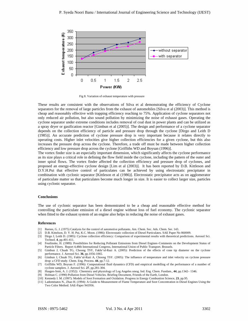
Fig 8. Variation of exhaust temperature with pressure
These results are consistent with the observations of Silva et al demonstrating the efficiency of Cyclone separators for the removal of large particles from the exhaust of automobiles [Silva et al (2003)]. This method is cheap and reasonably effective with trapping efficiency reaching to 75%. Application of cyclone separators not only reduced air pollution, but also sound pollution by minimizing the noise of exhaust gases. Operating the cyclone separator under extreme conditions includes removal of coal dust in power plants and can be utilized as a spray dryer or gasification reactor [Gimbun et al (2005)]. The design and performance of a cyclone separator depends on the collection efficiency of particle and pressure drop through the cyclone [Dirgo and Leith D (1985)]. An accurate prediction of cyclone pressure drop is very important because it relates directly to operating costs. Higher inlet velocities give higher collection efficiencies for a given cyclone, but this also increases the pressure drop across the cyclone. Therefore, a trade off must be made between higher collection efficiency and low pressure drop across the cyclone [Griffiths WD and Boysan (1996)]. The vortex finder size is an especially important dimension, which significantly affects the cyclone performance as its size plays a critical role in defining the flow field inside the cyclone, including the pattern of the outer and inner spiral flows. The vortex finder affected the collection efficiency and pressure drop of cyclones, and proposed an energy-effective cyclone design [Lim et al (2003)]. It has been reported by D.B. Kittleson and D.Y.H.Pui that effective control of particulates can be achieved by using electrostatic precipitator in combination with cyclonic separator [Kittleson et al (1986)]. Electrostatic precipitator acts as on agglomerator of particulate matter so that particulates become much longer in size. It is easier to collect larger size, particles using cyclonic separator. Conclusions The use of cyclonic separator has been demonstrated to be a cheap and reasonable effective method for controlling the particulate emission of a diesel engine without loss of fuel economy. The cyclonic separator when fitted to the exhaust system of an engine also helps in reducing the noise of exhaust gases. References
[1] Barnes, G. J. (1975) Catalysis for the control of automotive pollutants. Am. Chem. Soc. Ads. Chem. Ser. 143. [2] D.B. Kittelson, D. Y. H. Pui, K.C. Moon. (1986): Electrostatic collection of Diesel Particulates. SAE Paper No 860009. [3] Dirgo J, Leith D. (1985): Cyclone collection efficiency: Comparison of experimental results with theoretical predictions. Aerosol Sci.
Technol. 4, pp.401-411. [4] Feutlinske, H. (1989): Possibilities for Reducing Pollutant Emissions from Diesel Engines–Comments on the Development Status of
Particle Filters. Report 4,48th International Congress, International Union of Public Transport. Brussels. [5] Gimbun J, Chuah TG, Choong TSY, Fakhr’ul-Razi A. (2005): Prediction of the effects of cone tip diameter on the cyclone
performance. J. Aerosol Sci. 36, pp.1056-1065. [6] Gimbun J, Chuah TG, Fakhr’ul-Razi A, Choong TSY. (2005): The influence of temperature and inlet velocity on cyclone pressure
drop: a CFD study. Chem. Eng. Process. 44, pp.7-12. [7] Griffiths WD, Boysan F. (1996): Computational fluid dynamics (CFD) and empirical modelling of the performance of a number of
cyclone samplers. J. Aerosol Sci. 27, pp.281-304. [8] Haagen-Smit, A. J. (1952): Chemistry and physiology of Log Angeles smog. Ind. Eng. Chem. Fundam., 44, pp.1342– 1346. [9] Holman C. (1990) Pollution from Diesel Vehicles. Briefing Document, Friends of the Earth, London. [10] Kennedy I. M. (1997): Models of Soot Formation and Oxidation. Progress in Energy Combustion Science, 23, pp.95. [11] Ladommatos N., Zhao H. (1994): A Guide to Measurement of Flame Temperature and Soot Concentration in Diesel Engines Using the
Two Color Method. SAE-Paper 941956.
P. Syeda Noori Banu / International Journal of Engineering Science and Technology (IJEST)
ISSN : 0975-5462 Vol. 3 No. 4 Apr 2011 3302

[12] Lim KS, Kwon SB, Lee KW. (2003): Characteristics of the collection efficiency for a double inlet cyclone with clean air. J. Aerosol Sci. 34, pp.1085-1095.
[13] Silva PD, Briens C, Bernis A. (2003): Development of a new rapid method to measure erosion rates in laboratory and pilot plant cyclones. Powder Technol. 131, pp.111-119.
[14] V.A. Reznik and V.V. Mastnev. (1971): Thermal Engineering. [15] Valavanidis A, Fiotakis K, Vlachogianni T. (2008): Airborne particulate matter and human health: toxicological assessment and
importance of size and composition of particles for oxidative damage and carcinogenic mechanisms. J Environ Sci Health C Environ Carcinog Ecotoxicol Rev. 26(4), 339-62.
P. Syeda Noori Banu / International Journal of Engineering Science and Technology (IJEST)
ISSN : 0975-5462 Vol. 3 No. 4 Apr 2011 3303