Design and control of an ethyl acetate process: coupled...
15
Design and control of an ethyl acetate process: coupled reactor/column configuration I-Lung Chien a, * , Yao-Pin Teng a , Hsiao-Ping Huang b , Yeong Tarng Tang b a Department of Chemical Engineering, National Taiwan University of Science and Technology, 43, Keelung Road, Sec. 4, Taipei 106, Taiwan, ROC b Department of Chemical Engineering, National Taiwan University, 1 Roosevelt Road, Sec. 4, Taipei 106, Taiwan, ROC Received 6 January 2004; received in revised form 1 June 2004; accepted 8 July 2004 Abstract In this paper, design and control of a realistic coupled reactor/column process to produce ethyl acetate is studied. The process design is more complicated because the ethyl acetate product is neither the lightest nor the heaviest component in the system. A search procedure is proposed to obtain the optimum process design and operating condition of this process. The optimum process design is the one that minimize the Total Annual Cost (TAC) of this process while satisfying the stringent product impurity spec- ifications. The optimum overall process design includes a continuous-stirred tank reactor (CSTR) coupled with a rectifier, a decan- ter, another stripper, and a recycle stream. After the process design is established, the next step is to use dynamic simulation to test the appropriate control strategy for this process. Sensitivity analysis is performed to obtain the suitable temperature control points for the columns. The proposed control strategy is very simple containing only one temperature control loop in each column. This recommended simpler control strategy uses the ratio of acetic acid feed rate to ethanol feed rate to control the 5th stage temperature of the rectifier and uses the stripper reboiler duty to control the 5th stage temperature of the stripper. The proposed control strategy does not need any on-line composition measurements and can properly hold product purity in spite of feed flow rate and feed com- position disturbances. For small deviations of the product impurity compositions during disturbances, a slow cascade outer com- position loop structure can be implemented using off-line composition measurements from the quality lab. Ó 2004 Elsevier Ltd. All rights reserved. Keywords: Ethyl acetate process; Coupled reactor/column; Process design; Plant-wide control 1. Introduction Ethyl acetate is an important organic solvent widely used in the production of varnishes, ink, synthetic resins, and adhesive agents. Ethyl acetate (EtAc) is normally produced via reversible reaction of acetic acid (HAc) with ethanol (EtOH). There are only a few papers in the literature on the subject of the production of ethyl acetate via reactive distillation. For steady-state simula- tion of ethyl acetate reactive distillation column, Chang and Seader [1] used homotopy-continuation method to solve the steady-state simulation on an ethyl acetate reactive distillation column. Simandl and Svrcek [2] in- stead used inside–outside method for the steady-state simulation. For dynamic simulation, Alejski and Duprat [3] formulated a dynamic mathematical model of a reac- tive distillation and validated the accuracy of the simpli- fied model via experimental data. All of the above simulations did not obtain high-purity ethyl acetate product and did not consider the possible liquid–liquid equilibrium in the system. For the process design of this system with reactive distillation column, Keyes [4] was, perhaps, the first re- ported paper on an ethyl acetate process using a reactive distillation column in combination with a pre-esterifica- tion reactor, two recovery columns, and a decanter. His 0959-1524/$ - see front matter Ó 2004 Elsevier Ltd. All rights reserved. doi:10.1016/j.jprocont.2004.07.003 * Corresponding author. Tel.: +886 2 27376652; fax: +886 2 27376644. E-mail address: [email protected] (I-L. Chien). www.elsevier.com/locate/jprocont Journal of Process Control 15 (2005) 435–449
Transcript of Design and control of an ethyl acetate process: coupled...

www.elsevier.com/locate/jprocont
Journal of Process Control 15 (2005) 435–449
Design and control of an ethyl acetate process: coupledreactor/column configuration
I-Lung Chien a,*, Yao-Pin Teng a, Hsiao-Ping Huang b, Yeong Tarng Tang b
a Department of Chemical Engineering, National Taiwan University of Science and Technology, 43, Keelung Road, Sec. 4, Taipei 106, Taiwan, ROCb Department of Chemical Engineering, National Taiwan University, 1 Roosevelt Road, Sec. 4, Taipei 106, Taiwan, ROC
Received 6 January 2004; received in revised form 1 June 2004; accepted 8 July 2004
Abstract
In this paper, design and control of a realistic coupled reactor/column process to produce ethyl acetate is studied. The processdesign is more complicated because the ethyl acetate product is neither the lightest nor the heaviest component in the system. Asearch procedure is proposed to obtain the optimum process design and operating condition of this process. The optimum processdesign is the one that minimize the Total Annual Cost (TAC) of this process while satisfying the stringent product impurity spec-ifications. The optimum overall process design includes a continuous-stirred tank reactor (CSTR) coupled with a rectifier, a decan-ter, another stripper, and a recycle stream. After the process design is established, the next step is to use dynamic simulation to testthe appropriate control strategy for this process. Sensitivity analysis is performed to obtain the suitable temperature control pointsfor the columns. The proposed control strategy is very simple containing only one temperature control loop in each column. Thisrecommended simpler control strategy uses the ratio of acetic acid feed rate to ethanol feed rate to control the 5th stage temperatureof the rectifier and uses the stripper reboiler duty to control the 5th stage temperature of the stripper. The proposed control strategydoes not need any on-line composition measurements and can properly hold product purity in spite of feed flow rate and feed com-position disturbances. For small deviations of the product impurity compositions during disturbances, a slow cascade outer com-position loop structure can be implemented using off-line composition measurements from the quality lab.� 2004 Elsevier Ltd. All rights reserved.
Keywords: Ethyl acetate process; Coupled reactor/column; Process design; Plant-wide control
1. Introduction
Ethyl acetate is an important organic solvent widelyused in the production of varnishes, ink, synthetic resins,and adhesive agents. Ethyl acetate (EtAc) is normallyproduced via reversible reaction of acetic acid (HAc)with ethanol (EtOH). There are only a few papers inthe literature on the subject of the production of ethylacetate via reactive distillation. For steady-state simula-tion of ethyl acetate reactive distillation column, Changand Seader [1] used homotopy-continuation method to
0959-1524/$ - see front matter � 2004 Elsevier Ltd. All rights reserved.doi:10.1016/j.jprocont.2004.07.003
* Corresponding author. Tel.: +886 2 27376652; fax: +886 227376644.
E-mail address: [email protected] (I-L. Chien).
solve the steady-state simulation on an ethyl acetatereactive distillation column. Simandl and Svrcek [2] in-stead used inside–outside method for the steady-statesimulation. For dynamic simulation, Alejski and Duprat[3] formulated a dynamic mathematical model of a reac-tive distillation and validated the accuracy of the simpli-fied model via experimental data. All of the abovesimulations did not obtain high-purity ethyl acetateproduct and did not consider the possible liquid–liquidequilibrium in the system.
For the process design of this system with reactivedistillation column, Keyes [4] was, perhaps, the first re-ported paper on an ethyl acetate process using a reactivedistillation column in combination with a pre-esterifica-tion reactor, two recovery columns, and a decanter. His

436 I-L. Chien et al. / Journal of Process Control 15 (2005) 435–449
process is quite complex and contains quite a few proc-ess equipments. Bock et al. [5] designed an uncatalyzedethyl acetate process with excess ethanol containing areactive distillation column and a pressurized recoverycolumn. Although high-purity ethyl acetate productcan be obtained from the bottom of the recovery col-umn, the top product containing EtOH/EtAc/H2O hasto be recycled back to the reactive distillation column,and, the bottom of the reactive distillation column con-taining EtOH/H2O which needs further treatment. Voraand Daoutidis [6] studied the operation and control of asingle reactive distillation column. The top product isnot pure enough, and also the bottom product streamcontains all four components in the system. Thus, it willbe very difficult for further treatment of the bottomstream. Recently, Tang et al. [7] proposed an overalloptimum design of ethyl acetate reactive distillation sys-tem. Their overall design includes two columns (onereactive distillation column and a second stripping col-umn), one decanter, and two recycle streams.
In this paper, an alternative process design other thanthe reactive distillation column is used to produce ethylacetate. A coupled reactor/column configuration will beexplored. The principal behind the coupled reactor/col-umn system, similar to reactive distillation, is that thecontinuous removal of products from the reaction mix-ture by distillation reduces the backward reaction rate.The advantages of the coupled reactor/column configu-ration over reactive distillation column according to Yiand Luyben [8] include: the existing reactor and distilla-tion column in the plant can be retrofitted for this usage,easy catalyst replacement, and larger reactor holdup caneasily be designed, etc. In a three-paper series by Yi andLuyben [8–10], they studied the design and control ofvarious coupled reactor/column systems. The studiedsystems include: a binary reactor/rectifier, a binaryreactor/stripper, a multicomponent reactor/rectifier, amulticomponent reactor/rectifier/stripper, and a morecomplex process that consists of a coupled reactor/strip-per, two distillation columns and one recycle stream.Their studied systems are very simple, ideal chemicalsystems and also no liquid–liquid equilibrium is consid-ered. Chiang et al. [11] studied a coupled reactor/columnsystem for the production of amyl acetate. Their processis much simpler than the ethyl acetate process becauseamyl acetate has the highest boiling point in the system.Their system with the configuration of reactor/rectifier/stripper produces amyl acetate from the bottom of thestripper and also produces water through aqueous phaseof a decanter.
In the case of ethyl acetate production, the completeprocess configuration will need to be more complex be-cause the ethyl acetate and water products are neitherthe lightest nor the heaviest component in the system.Burkett and Rossiter [12] studied the control strategyof a reactive distillation column with the reaction
occurred at the base of a distillation column which issimilar to the coupled reactor/column system that willbe investigated in this paper. In their system, the top va-por of the column after condensation separates into twoliquid phases with the organic phase as the ethyl acetateproduct. However, the composition of the ethyl acetateproduct is not pure enough for industrial usage and alsono detailed design condition or detailed control study isgiven in their paper.
The organization of this paper is as follows. The opti-mum design of a complete coupled reactor/column sys-tem will be proposed in Section 2. A search procedurewill be given to obtain the optimum process designand operating condition of this process. The controlstrategy development of this process will be presentedin Section 3. Sensitivity analysis is performed to obtainthe suitable temperature control points inside the col-umn. Closed-loop dynamic simulation will be used toevaluate the performance of the proposed control strat-egy. The proposed control strategy needs to hold prod-uct purity despite feed flow rate and feed compositiondisturbances. Some concluding remarks will be givenin Section 4.
2. Optimum process design and operating condition
2.1. Conceptual design of the overall coupled reactor/
column system
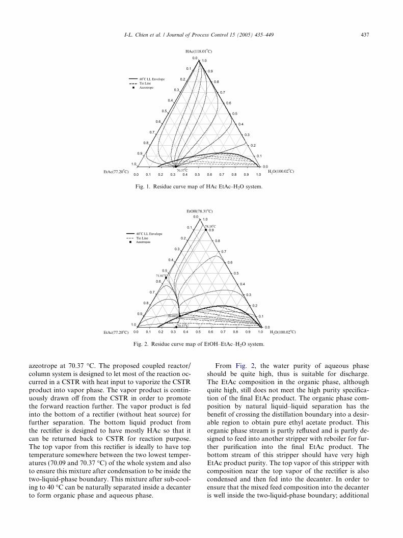
The thermodynamic model used in this study is thesame as the one in Tang et al. [7]. A suitable NTRL(nonrandom two-liquid) model parameter set has beenestablished with excellent prediction of the compositionsand temperatures for the four azeotropes in this system.Vapor association of acetic acid due to dimerization hasalso been included by using the second virial coefficientof Hayden–O�Connell model [13] for the vapor phase.The predicted four azeotropes in this system includethree homogeneous azeotropes of EtOH–EtAc, EtOH–H2O, and EtOH–EtAc–H2O and also one heterogene-ous azeotrope of EtAc–H2O. The computed azeotropiccompositions and temperatures agree very well withthe experimental data in the open literature. This ther-modynamic model set also predicted all binary VLEand all ternary LLE very well in comparison with theexperimental data. The residue curve maps of three-component HAc–EtAc–H2O and also EtOH–EtAc–H2O are shown in Figs. 1 and 2.
From Figs. 1 and 2, the highest boiling point temper-ature of the whole system including the pure compo-nents and azeotropes is the acetic acid (HAc) at 118.01�C and the lowest temperature of the whole system isthe EtOH–EtAc–H2O three-component azeotrope at70.09 �C. The next lowest temperature of the whole sys-tem is the heterogeneous EtAc–H2O two-component
H2O(100.02oC)
0.0 0.1 0.2 0.3 0.4 0.5 0.6 0.7 0.8 0.9 1.0
HAc(118.01oC)
0.0
0.1
0.2
0.3
0.4
0.5
0.6
0.7
0.8
0.9
1.0
EtAc(77.20oC)
0.0
0.1
0.2
0.3
0.4
0.5
0.6
0.7
0.8
0.9
1.0
40oC LL EnvelopeTie Line Azeotrope
70.37oC
Fig. 1. Residue curve map of HAc EtAc–H2O system.
H2O(100.02oC)0.0 0.1 0.2 0.3 0.4 0.5 0.6 0.7 0.8 0.9 1.0
EtOH(78.31oC)
0.0
0.1
0.2
0.3
0.4
0.5
0.6
0.7
0.8
0.9
1.0
EtAc(77.20oC)
0.0
0.1
0.2
0.3
0.4
0.5
0.6
0.7
0.8
0.9
1.0
40oC LL EnvelopeTie Line Azeotropes
78.18oC
70.09oC
70.37oC
71.81oC
Fig. 2. Residue curve map of EtOH–EtAc–H2O system.
I-L. Chien et al. / Journal of Process Control 15 (2005) 435–449 437
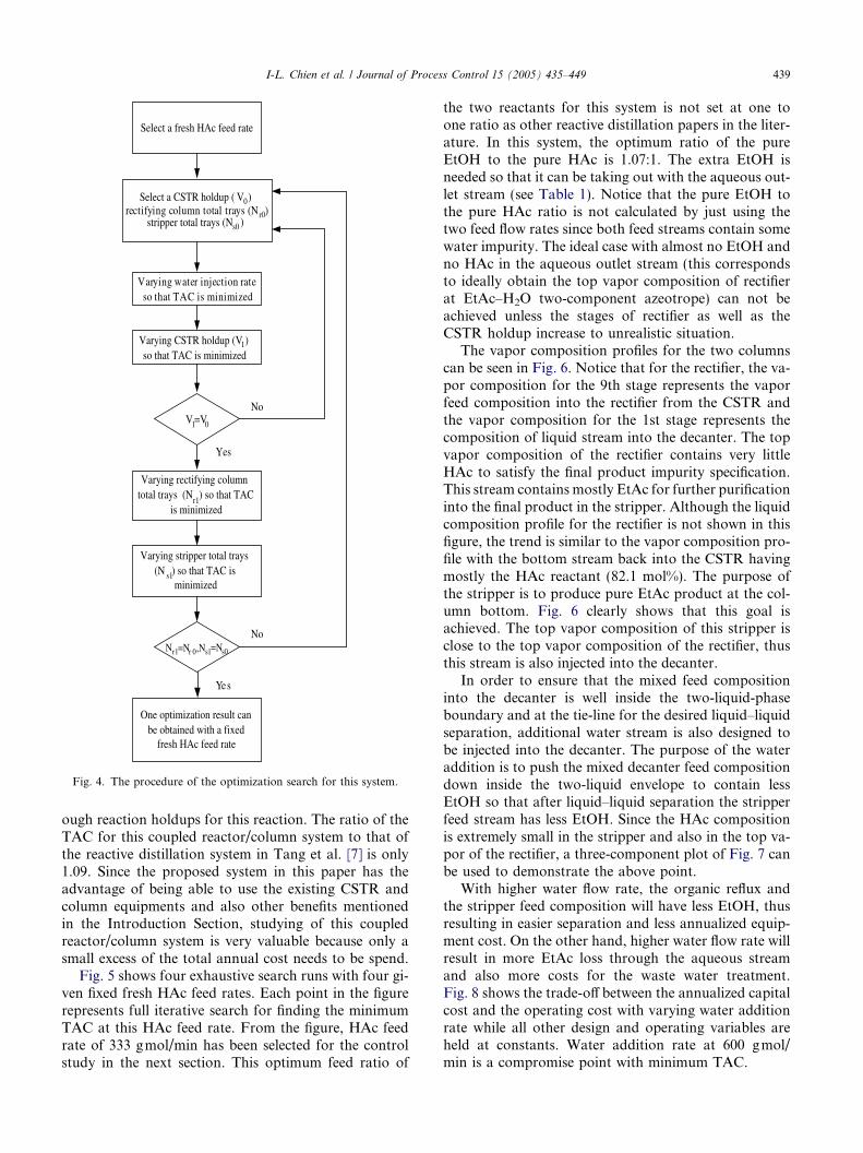
azeotrope at 70.37 �C. The proposed coupled reactor/column system is designed to let most of the reaction oc-curred in a CSTR with heat input to vaporize the CSTRproduct into vapor phase. The vapor product is contin-uously drawn off from the CSTR in order to promotethe forward reaction further. The vapor product is fedinto the bottom of a rectifier (without heat source) forfurther separation. The bottom liquid product fromthe rectifier is designed to have mostly HAc so that itcan be returned back to CSTR for reaction purpose.The top vapor from this rectifier is ideally to have toptemperature somewhere between the two lowest temper-atures (70.09 and 70.37 �C) of the whole system and alsoto ensure this mixture after condensation to be inside thetwo-liquid-phase boundary. This mixture after sub-cool-ing to 40 �C can be naturally separated inside a decanterto form organic phase and aqueous phase.
From Fig. 2, the water purity of aqueous phaseshould be quite high, thus is suitable for discharge.The EtAc composition in the organic phase, althoughquite high, still does not meet the high purity specifica-tion of the final EtAc product. The organic phase com-position by natural liquid–liquid separation has thebenefit of crossing the distillation boundary into a desir-able region to obtain pure ethyl acetate product. Thisorganic phase stream is partly refluxed and is partly de-signed to feed into another stripper with reboiler for fur-ther purification into the final EtAc product. Thebottom stream of this stripper should have very highEtAc product purity. The top vapor of this stripper withcomposition near the top vapor of the rectifier is alsocondensed and then fed into the decanter. In order toensure that the mixed feed composition into the decanteris well inside the two-liquid-phase boundary; additional
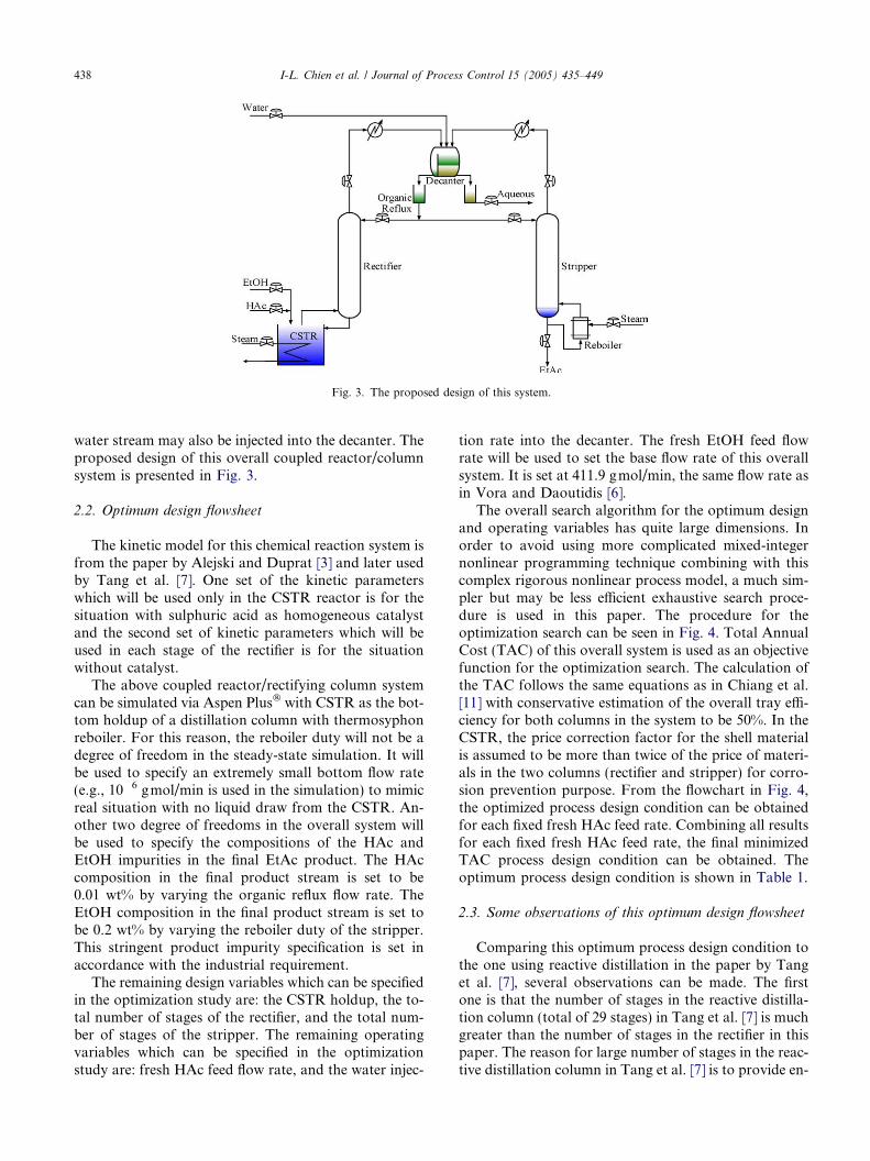
Fig. 3. The proposed design of this system.
438 I-L. Chien et al. / Journal of Process Control 15 (2005) 435–449
water stream may also be injected into the decanter. Theproposed design of this overall coupled reactor/columnsystem is presented in Fig. 3.
2.2. Optimum design flowsheet
The kinetic model for this chemical reaction system isfrom the paper by Alejski and Duprat [3] and later usedby Tang et al. [7]. One set of the kinetic parameterswhich will be used only in the CSTR reactor is for thesituation with sulphuric acid as homogeneous catalystand the second set of kinetic parameters which will beused in each stage of the rectifier is for the situationwithout catalyst.
The above coupled reactor/rectifying column systemcan be simulated via Aspen Plus� with CSTR as the bot-tom holdup of a distillation column with thermosyphonreboiler. For this reason, the reboiler duty will not be adegree of freedom in the steady-state simulation. It willbe used to specify an extremely small bottom flow rate(e.g., 10�6 gmol/min is used in the simulation) to mimicreal situation with no liquid draw from the CSTR. An-other two degree of freedoms in the overall system willbe used to specify the compositions of the HAc andEtOH impurities in the final EtAc product. The HAccomposition in the final product stream is set to be0.01 wt% by varying the organic reflux flow rate. TheEtOH composition in the final product stream is set tobe 0.2 wt% by varying the reboiler duty of the stripper.This stringent product impurity specification is set inaccordance with the industrial requirement.
The remaining design variables which can be specifiedin the optimization study are: the CSTR holdup, the to-tal number of stages of the rectifier, and the total num-ber of stages of the stripper. The remaining operatingvariables which can be specified in the optimizationstudy are: fresh HAc feed flow rate, and the water injec-
tion rate into the decanter. The fresh EtOH feed flowrate will be used to set the base flow rate of this overallsystem. It is set at 411.9 gmol/min, the same flow rate asin Vora and Daoutidis [6].
The overall search algorithm for the optimum designand operating variables has quite large dimensions. Inorder to avoid using more complicated mixed-integernonlinear programming technique combining with thiscomplex rigorous nonlinear process model, a much sim-pler but may be less efficient exhaustive search proce-dure is used in this paper. The procedure for theoptimization search can be seen in Fig. 4. Total AnnualCost (TAC) of this overall system is used as an objectivefunction for the optimization search. The calculation ofthe TAC follows the same equations as in Chiang et al.[11] with conservative estimation of the overall tray effi-ciency for both columns in the system to be 50%. In theCSTR, the price correction factor for the shell materialis assumed to be more than twice of the price of materi-als in the two columns (rectifier and stripper) for corro-sion prevention purpose. From the flowchart in Fig. 4,the optimized process design condition can be obtainedfor each fixed fresh HAc feed rate. Combining all resultsfor each fixed fresh HAc feed rate, the final minimizedTAC process design condition can be obtained. Theoptimum process design condition is shown in Table 1.
2.3. Some observations of this optimum design flowsheet
Comparing this optimum process design condition tothe one using reactive distillation in the paper by Tanget al. [7], several observations can be made. The firstone is that the number of stages in the reactive distilla-tion column (total of 29 stages) in Tang et al. [7] is muchgreater than the number of stages in the rectifier in thispaper. The reason for large number of stages in the reac-tive distillation column in Tang et al. [7] is to provide en-
Select a fresh HAc feed rate
Select a CSTR holdup ( V0)rectifying column total trays (Nr0)
stripper total trays (Ns0 )
Varying water injection rateso that TAC is minimized
Varying CSTR holdup (V1)so that TAC is minimized
V1=V0
Yes
No
Varying rectifying columntotal trays (Nr1) so that TAC
is minimized
Varying stripper total trays(N s1) so that TAC is
minimized
Nr1=Nr 0,Ns1=Ns0
Yes
No
One optimization result canbe obtained with a fixed
fresh HAc feed rate
Fig. 4. The procedure of the optimization search for this system.
I-L. Chien et al. / Journal of Process Control 15 (2005) 435–449 439
ough reaction holdups for this reaction. The ratio of theTAC for this coupled reactor/column system to that ofthe reactive distillation system in Tang et al. [7] is only1.09. Since the proposed system in this paper has theadvantage of being able to use the existing CSTR andcolumn equipments and also other benefits mentionedin the Introduction Section, studying of this coupledreactor/column system is very valuable because only asmall excess of the total annual cost needs to be spend.
Fig. 5 shows four exhaustive search runs with four gi-ven fixed fresh HAc feed rates. Each point in the figurerepresents full iterative search for finding the minimumTAC at this HAc feed rate. From the figure, HAc feedrate of 333 gmol/min has been selected for the controlstudy in the next section. This optimum feed ratio of
the two reactants for this system is not set at one toone ratio as other reactive distillation papers in the liter-ature. In this system, the optimum ratio of the pureEtOH to the pure HAc is 1.07:1. The extra EtOH isneeded so that it can be taking out with the aqueous out-let stream (see Table 1). Notice that the pure EtOH tothe pure HAc ratio is not calculated by just using thetwo feed flow rates since both feed streams contain somewater impurity. The ideal case with almost no EtOH andno HAc in the aqueous outlet stream (this correspondsto ideally obtain the top vapor composition of rectifierat EtAc–H2O two-component azeotrope) can not beachieved unless the stages of rectifier as well as theCSTR holdup increase to unrealistic situation.
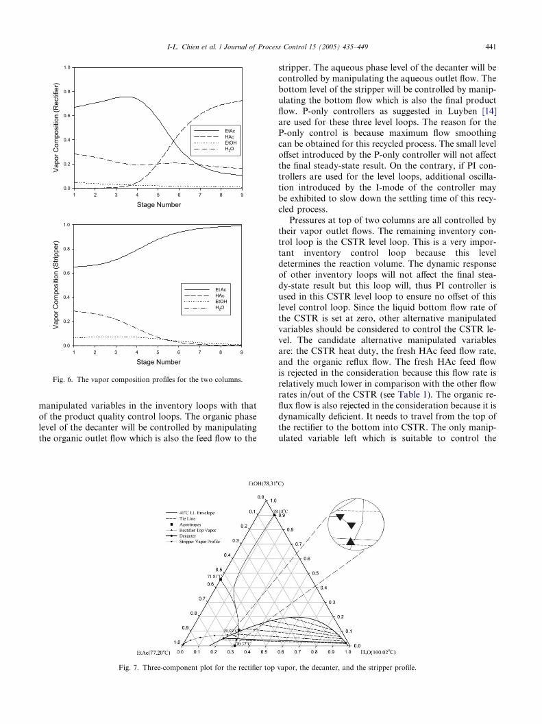
The vapor composition profiles for the two columnscan be seen in Fig. 6. Notice that for the rectifier, the va-por composition for the 9th stage represents the vaporfeed composition into the rectifier from the CSTR andthe vapor composition for the 1st stage represents thecomposition of liquid stream into the decanter. The topvapor composition of the rectifier contains very littleHAc to satisfy the final product impurity specification.This stream contains mostly EtAc for further purificationinto the final product in the stripper. Although the liquidcomposition profile for the rectifier is not shown in thisfigure, the trend is similar to the vapor composition pro-file with the bottom stream back into the CSTR havingmostly the HAc reactant (82.1 mol%). The purpose ofthe stripper is to produce pure EtAc product at the col-umn bottom. Fig. 6 clearly shows that this goal isachieved. The top vapor composition of this stripper isclose to the top vapor composition of the rectifier, thusthis stream is also injected into the decanter.
In order to ensure that the mixed feed compositioninto the decanter is well inside the two-liquid-phaseboundary and at the tie-line for the desired liquid–liquidseparation, additional water stream is also designed tobe injected into the decanter. The purpose of the wateraddition is to push the mixed decanter feed compositiondown inside the two-liquid envelope to contain lessEtOH so that after liquid–liquid separation the stripperfeed stream has less EtOH. Since the HAc compositionis extremely small in the stripper and also in the top va-por of the rectifier, a three-component plot of Fig. 7 canbe used to demonstrate the above point.
With higher water flow rate, the organic reflux andthe stripper feed composition will have less EtOH, thusresulting in easier separation and less annualized equip-ment cost. On the other hand, higher water flow rate willresult in more EtAc loss through the aqueous streamand also more costs for the waste water treatment.Fig. 8 shows the trade-off between the annualized capitalcost and the operating cost with varying water additionrate while all other design and operating variables areheld at constants. Water addition rate at 600 gmol/min is a compromise point with minimum TAC.
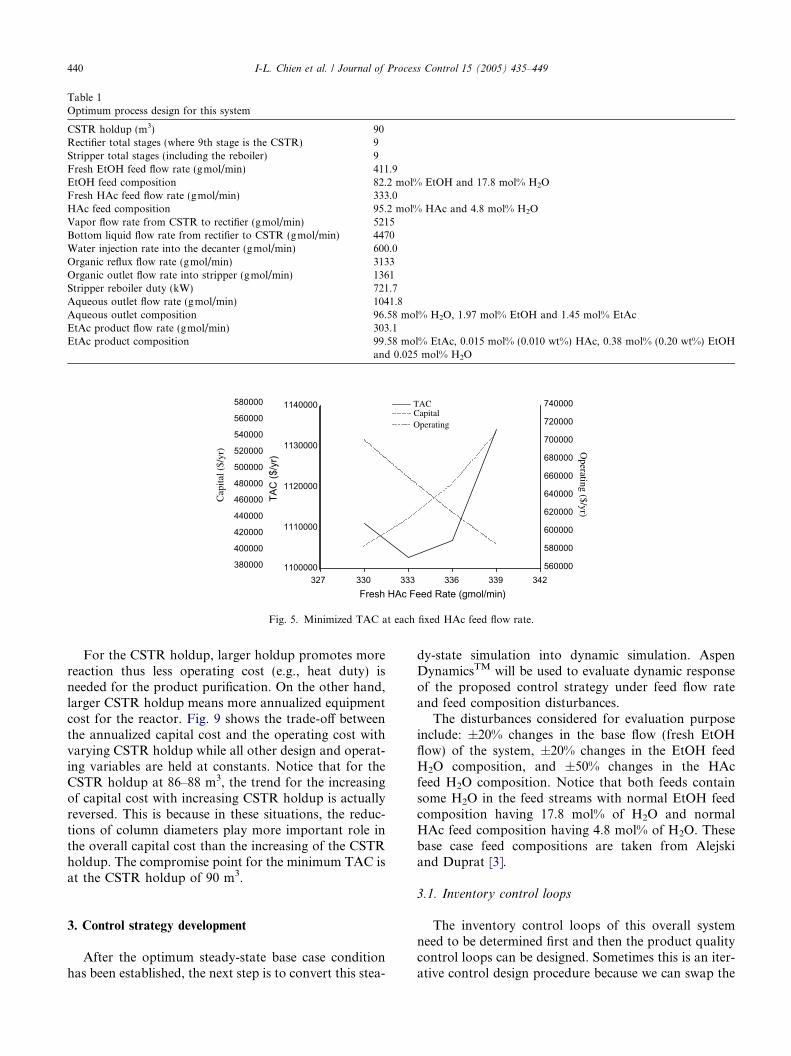
Table 1Optimum process design for this system
CSTR holdup (m3) 90Rectifier total stages (where 9th stage is the CSTR) 9Stripper total stages (including the reboiler) 9Fresh EtOH feed flow rate (gmol/min) 411.9EtOH feed composition 82.2 mol% EtOH and 17.8 mol% H2OFresh HAc feed flow rate (gmol/min) 333.0HAc feed composition 95.2 mol% HAc and 4.8 mol% H2OVapor flow rate from CSTR to rectifier (gmol/min) 5215Bottom liquid flow rate from rectifier to CSTR (gmol/min) 4470Water injection rate into the decanter (gmol/min) 600.0Organic reflux flow rate (gmol/min) 3133Organic outlet flow rate into stripper (gmol/min) 1361Stripper reboiler duty (kW) 721.7Aqueous outlet flow rate (gmol/min) 1041.8Aqueous outlet composition 96.58 mol% H2O, 1.97 mol% EtOH and 1.45 mol% EtAcEtAc product flow rate (gmol/min) 303.1EtAc product composition 99.58 mol% EtAc, 0.015 mol% (0.010 wt%) HAc, 0.38 mol% (0.20 wt%) EtOH
and 0.025 mol% H2O
327 330 333 336 339 3421100000
1110000
1120000
1130000
1140000
380000
400000
420000
440000
460000
480000
500000
520000
540000
560000
580000
560000
580000
600000
620000
640000
660000
680000
700000
720000
740000 TAC
TAC
($/y
r)
Fresh HAc Feed Rate (gmol/min)
Capital
Cap
ital (
$/yr
) Operating ($/yr)
Operating
Fig. 5. Minimized TAC at each fixed HAc feed flow rate.
440 I-L. Chien et al. / Journal of Process Control 15 (2005) 435–449
For the CSTR holdup, larger holdup promotes morereaction thus less operating cost (e.g., heat duty) isneeded for the product purification. On the other hand,larger CSTR holdup means more annualized equipmentcost for the reactor. Fig. 9 shows the trade-off betweenthe annualized capital cost and the operating cost withvarying CSTR holdup while all other design and operat-ing variables are held at constants. Notice that for theCSTR holdup at 86–88 m3, the trend for the increasingof capital cost with increasing CSTR holdup is actuallyreversed. This is because in these situations, the reduc-tions of column diameters play more important role inthe overall capital cost than the increasing of the CSTRholdup. The compromise point for the minimum TAC isat the CSTR holdup of 90 m3.
3. Control strategy development
After the optimum steady-state base case conditionhas been established, the next step is to convert this stea-
dy-state simulation into dynamic simulation. AspenDynamicsTM will be used to evaluate dynamic responseof the proposed control strategy under feed flow rateand feed composition disturbances.
The disturbances considered for evaluation purposeinclude: ±20% changes in the base flow (fresh EtOHflow) of the system, ±20% changes in the EtOH feedH2O composition, and ±50% changes in the HAcfeed H2O composition. Notice that both feeds containsome H2O in the feed streams with normal EtOH feedcomposition having 17.8 mol% of H2O and normalHAc feed composition having 4.8 mol% of H2O. Thesebase case feed compositions are taken from Alejskiand Duprat [3].
3.1. Inventory control loops
The inventory control loops of this overall systemneed to be determined first and then the product qualitycontrol loops can be designed. Sometimes this is an iter-ative control design procedure because we can swap the
Stage Number1 2 3 4 5 6 7 8 9
Vapo
r Com
posi
tion
(Rec
tifie
r)
0.0
0.2
0.4
0.6
0.8
1.0
EtAcHAcEtOHH2O
Stage Number1 2 3 4 5 6 7 8 9
Vapo
r Com
posi
tion
(Stri
pper
)
0.0
0.2
0.4
0.6
0.8
1.0
Et AcHAcEtOHH2O
Fig. 6. The vapor composition profiles for the two columns.
I-L. Chien et al. / Journal of Process Control 15 (2005) 435–449 441
manipulated variables in the inventory loops with thatof the product quality control loops. The organic phaselevel of the decanter will be controlled by manipulatingthe organic outlet flow which is also the feed flow to the
Fig. 7. Three-component plot for the rectifier top
stripper. The aqueous phase level of the decanter will becontrolled by manipulating the aqueous outlet flow. Thebottom level of the stripper will be controlled by manip-ulating the bottom flow which is also the final productflow. P-only controllers as suggested in Luyben [14]are used for these three level loops. The reason for theP-only control is because maximum flow smoothingcan be obtained for this recycled process. The small leveloffset introduced by the P-only controller will not affectthe final steady-state result. On the contrary, if PI con-trollers are used for the level loops, additional oscilla-tion introduced by the I-mode of the controller maybe exhibited to slow down the settling time of this recy-cled process.
Pressures at top of two columns are all controlled bytheir vapor outlet flows. The remaining inventory con-trol loop is the CSTR level loop. This is a very impor-tant inventory control loop because this leveldetermines the reaction volume. The dynamic responseof other inventory loops will not affect the final stea-dy-state result but this loop will, thus PI controller isused in this CSTR level loop to ensure no offset of thislevel control loop. Since the liquid bottom flow rate ofthe CSTR is set at zero, other alternative manipulatedvariables should be considered to control the CSTR le-vel. The candidate alternative manipulated variablesare: the CSTR heat duty, the fresh HAc feed flow rate,and the organic reflux flow. The fresh HAc feed flowis rejected in the consideration because this flow rate isrelatively much lower in comparison with the other flowrates in/out of the CSTR (see Table 1). The organic re-flux flow is also rejected in the consideration because it isdynamically deficient. It needs to travel from the top ofthe rectifier to the bottom into CSTR. The only manip-ulated variable left which is suitable to control the
vapor, the decanter, and the stripper profile.

450 500 550 600 650 700 750
1100000
1102000
1104000
1106000
1108000
1110000
1112000
430000
440000
450000
460000
470000
480000
660000
662000
664000
666000
668000
670000
672000
674000 TAC
TAC
($/y
r)
Water Addition Rate (gmol/min)
Capital
Cap
ital (
$/yr
) O
perating ($/yr)
Operating
Fig. 8. Effect of water addition rate on TAC.
86 88 90 92 94
1096000
1098000
1100000
1102000
1104000
1106000
1108000
1110000
1112000
1114000
1116000
435000
440000
445000
450000
455000
460000
465000
470000
475000
480000
654000
657000
660000
663000
666000
669000
672000
675000
678000 TAC
TA
C (
$/yr
)
CSTR Holdup (m3)
Capital
Cap
ital (
$/yr
) Operating ($/yr)
Operating
Fig. 9. Effect of the CSTR holdup on TAC.
442 I-L. Chien et al. / Journal of Process Control 15 (2005) 435–449
CSTR level is the CSTR heat duty. This manipulatedvariable will affect the vapor flow leaving the CSTR thuschanging the CSTR level.
After deciding the overall inventory control loops,the remaining manipulated variables which can be usedin product purity control loops are: the fresh HAc feedflow, the organic reflux flow, the water injection rate,and the reboiler duty of the stripper. Ratio schemes willbe implemented to allow for some feedforward compen-sation for the measurable disturbances. The fresh HAcfeed flow rate will be ratio to the base flow rate of EtOH.The water injection rate will also be ratio to the baseflow rate of EtOH. These two ratios are set accordingto the base case condition in Table 1. The organic refluxflow rate will be ratio to the organic outlet flow rate sothat organic reflux ratio is held at a constant value as thebase case condition.
3.2. Selection of the temperature control point
Only tray temperature measurements will be consid-ered for inferential control of the final product purity.
The assumption of no available on-line compositionmeasurement agrees well with the real industrial situa-tion. In order to determine the proper temperature con-trol point(s), sensitivity analysis will be performed nextto determine the temperature control point(s). Sometray temperature in the rectifier will be used to inferthe HAc impurity in the final EtAc product stream. Thisis workable because any HAc impurity in the top vaporstream of the rectifier will be proportionally shown inthe final EtAc product stream. Certain tray temperaturein the stripper will be used to infer the EtOH impurity inthe final EtAc product stream. The sensitivity analysis atthe rectifier can be seen in the following Figs. 10 and 11for ±1% changes in the fresh HAc feed ratio and ±1%changes in the organic reflux ratio, respectively.
The first observation from these two figures of sensi-tivity analysis is that the fresh HAc feed ratio has thestrongest effect to the tray temperatures. Only small±1% changes in the fresh HAc feed ratio causes largechanges to the tray temperatures in the rectifier. Forcomparison, the effect due to ±1% changes in the organ-ic reflux ratio is much smaller than ±1% changes in the

Rectifier Stages
1 2 3 4 5 6 7 8 9
Tem
pera
ture
(o C)
70
80
90
100
110
120
130
Base Case+1% Feed Ratio-1% Feed Ratio
Fig. 10. ±1% changes in the fresh HAc feed ratio on temperature ateach stage.
Rectifier Stages
1 2 3 4 5 6 7 8 9
Tem
pera
ture
(o C)
70
80
90
100
110
120
130
Base Case+1% Organic Reflux Ratio-1% Organic Reflux Ratio
Fig. 11. ±1% changes in the organic reflux ratio on temperature ateach stage.
Rectifier Stages1 2 3 4 5 6 7 8 9
HAc
Vap
or C
ompo
sitio
n (m
ol. f
rac.
)
0.0
0.2
0.4
0.6
0.8
Base Case+1% Feed Ratio-1% Feed Ratio
Fig. 12. ±1% changes in the fresh HAc feed ratio on HAc vaporcomposition at each stage.
Stripper Stages
1 2 3 4 5 6 7 8 9
Tem
pera
ture
(o C)
74
76
78
80
82
84
86
Base Case+10% Stripper Q-10% Stripper Q
Fig. 13. ±10% changes in the reboiler duty of the stripper ontemperature at each stage.
I-L. Chien et al. / Journal of Process Control 15 (2005) 435–449 443
fresh HAc feed ratio. It is concluded that the fresh HAcfeed ratio should be used to control some stage temper-ature inside the rectifying column. The 5th stage temper-ature will be used as the control point because thesensitivity is large and also the behavior is quite linear.This quite linear behavior can be observed in Fig. 10by calculating the process gains for ±1% changes inthe fresh HAc feed ratio. Fig. 12 shows the HAc vaporcomposition profiles for ±1% changes in the fresh HAcfeed ratio. Notice that at the 5th stage the HAc vaporcomposition also varies significantly for ±1% changesin the fresh HAc feed ratio. The sensitivity of composi-tion and temperature corresponds well at the 5th stage.The sensitivity analysis at the stripper can be seen in Fig.13 for ±10% changes in the reboiler duty. From the fig-ure, the 5th stage temperature should be used as the con-trol point by manipulating the reboiler duty.
3.3. Tuning of the two temperature control loops
The proposed overall control strategy is presented inFig. 14. Notice that the ratio schemes are implementedfor the un-used organic reflux flow to maintain a con-stant organic reflux ratio. The water injection rate is alsovaried in accordance with the base EtOH feed flow rate.The IMC-PI tuning rules of Chien and Fruehauf [15]will be used to determine the PI tuning parameters ofthe two important temperature loops which infer the fi-nal product composition.
The initial dynamic responses of the open-loop stepchanges will be use to tune these two temperature loops.Fig. 15 shows the open-loop step response of the rectifier5th stage temperature with ±1% changes in the freshHAc feed ratio at time = 1 h. Only the first two hoursinitial dynamic responses are used to calculate the model

OrganicReflux
HAc
Steam
Aqueous
EtOH
Decanter
Steam
EtAc
Reboiler
Water
CSTR
PC PC
TC
LC
TC
LC
LC
LC
FC
FC
FC
FC
1 1
88
9
55
TC TC
X
X
X
Ratio Setpoint
Ratio Setpoint
Fig. 14. Proposed overall control strategy of this system.
444 I-L. Chien et al. / Journal of Process Control 15 (2005) 435–449
parameters of an integrating model with deadtime. Thedynamic responses with these small perturbations areobserved to be quite linear because symmetrical dy-namic behavior is observed in this figure. Once the mod-el parameters are obtained from the step test, the PItuning parameters can easily be calculated followingChien and Fruehauf [15]. The closed-loop tuningparameter, scl, is set to be twice of the apparent dead-time of this system. The PI tuning constants used inthe closed-loop simulations are: Kc = 15.9 and sI = 48min.
Fig. 16 shows the open-loop step response of thestripper 5th stage temperature with ±1% changes inthe reboiler duty at time = 1 h. Notice that the dynamic
Time(hr)0.0 0.5 1.0 1.5 2.0 2.5 3.0 3.5 4.0 4.5 5.0
5th S
tage
Tem
p of
Rec
tifie
r (o C
)
96.596.696.796.896.997.097.197.297.397.497.597.697.797.897.998.098.198.298.3
+1% Feed Ratio -1% Feed Ratio
Fig. 15. Open-loop initial dynamic response for ±1% changes in thefresh HAc feed ratio.
response is very unusual. Large overshoots are observedin this open-loop step test. The overshoot response ismainly due to the plantwide arrangement of this recycleprocess. The feed flow rate and its compositions arechanged considerably due to the recycle stream of thestripper top vapor. The overshoot response is due tothe composite dynamic response of the changes in thereboiler duty, feed flow rate, and the feed composition.Again, the initial dynamic response is most importantfor the controller tuning purpose. Only the initial dy-namic response (uses first 30 min to determine the modelparameters) is actually due to the changes in the reboilerduty alone, thus this part of the dynamic response isused for controller tuning purpose. Again, this system
Time(hr)0 1 2 3 4 5 6 7 8 9 10
5th S
tage
Tem
p of
Stri
pper
(o C)
80.1
80.2
80.3
80.4
80.5
80.6
80.7
80.8
80.9
81.0
81.1
81.2
81.3
81.4
81.5
81.6
+1% Stripper Q-1% Stripper Q
Fig. 16. Open-loop initial dynamic response for ±1% changes in thereboiler duty of the stripper.
I-L. Chien et al. / Journal of Process Control 15 (2005) 435–449 445
is modeled as an integrating process to obtain the PItuning parameters. The PI tuning constants for this loopare: Kc = 6.28 and sI = 20 min. One thing needs to bementioned is that this tuning strategy of emphasizingthe initial dynamic response needs to be modified whenencounters inverse-response system. In this case, thetime duration for the initial inverse response will be trea-ted as additional deadtime in the process model for con-troller tuning purpose.
3.4. Closed-loop simulation results
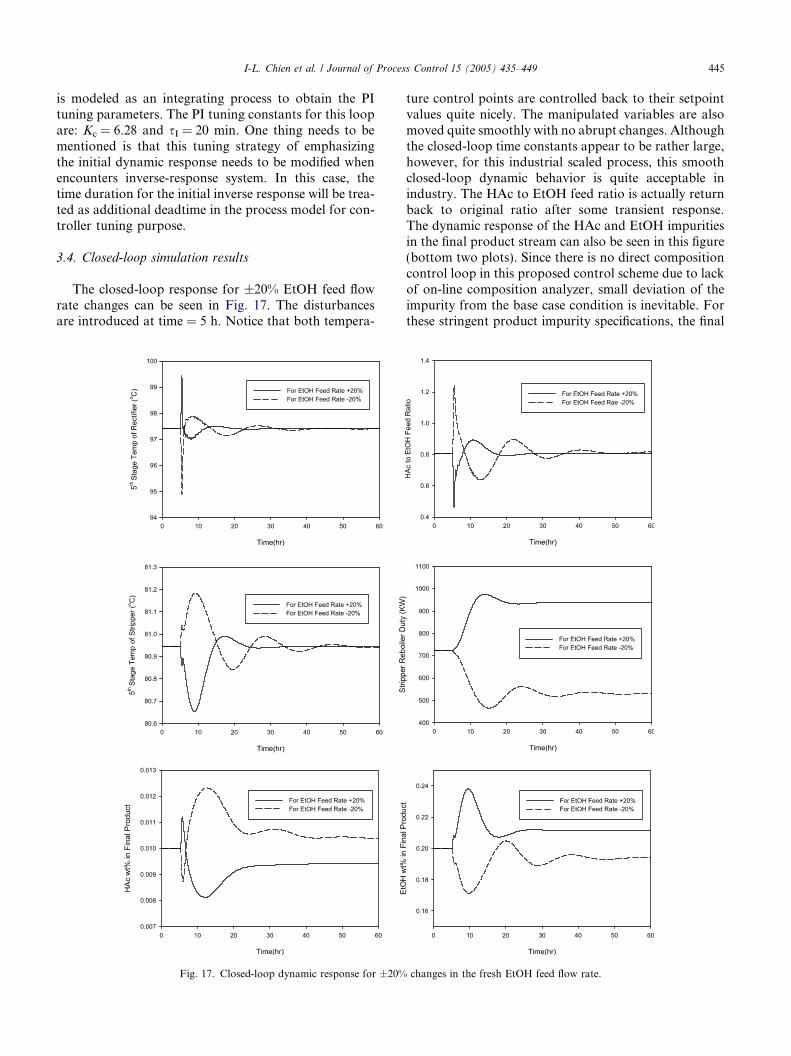
The closed-loop response for ±20% EtOH feed flowrate changes can be seen in Fig. 17. The disturbancesare introduced at time = 5 h. Notice that both tempera-
Fig. 17. Closed-loop dynamic response for ±20%
ture control points are controlled back to their setpointvalues quite nicely. The manipulated variables are alsomoved quite smoothly with no abrupt changes. Althoughthe closed-loop time constants appear to be rather large,however, for this industrial scaled process, this smoothclosed-loop dynamic behavior is quite acceptable inindustry. The HAc to EtOH feed ratio is actually returnback to original ratio after some transient response.The dynamic response of the HAc and EtOH impuritiesin the final product stream can also be seen in this figure(bottom two plots). Since there is no direct compositioncontrol loop in this proposed control scheme due to lackof on-line composition analyzer, small deviation of theimpurity from the base case condition is inevitable. Forthese stringent product impurity specifications, the final
changes in the fresh EtOH feed flow rate.

446 I-L. Chien et al. / Journal of Process Control 15 (2005) 435–449
deviations of the two product impurities are considered tobe quite small and satisfactory.
The above disturbance test can be viewed as howgood the overall control strategy performed withthroughput demand changes. Notice that the EtOH feedflow rate is assumed to be measurable, thus ratioschemes in this proposed control strategy are in actionto cope with this load change. The next two disturbancetests are unmeasured load changes. ±20% changes in theEtOH feed H2O composition and ±50% changes in theHAc feed H2O composition will be introduced into thissystem. The crucial evaluation is to show if the productimpurity specifications can also be approximately main-tained. Fig. 18 shows the closed-loop dynamic responsefor ±20% changes in the EtOH feed H2O composition.
Fig. 18. Closed-loop dynamic response for ±20%
Again, both temperature control points are controlledback to their setpoint values quite nicely. In this case,the HAc to EtOH feed ratio is changed to cope with thisunmeasured feed composition disturbance. The HAcimpurity in the product stream has more final steady-state deviation from the specification. The HAc impurityis going up to 0.0113 wt% for �20% changes in theEtOH feed H2O composition.
The closed-loop dynamic response for the ±50%changes in the HAc feed H2O composition is shown inFig. 19. From the figure, it is observed that the impactof this unmeasured load disturbance to the system issmaller than the previous one in Fig. 18. Both tempera-ture control points and the final product impurities areall behaved nicely.
changes in the EtOH feed H2O composition.

Fig. 19. Closed-loop dynamic response for ±50% changes in the HAc feed H2O composition.
I-L. Chien et al. / Journal of Process Control 15 (2005) 435–449 447
Since �20% changes in the EtOH feed H2O composi-tion causes the most steady-state deviation of the HAcimpurity specification in the above study, a practicalmethod is demonstrated next to bring the HAc impurityback to specification. Assumed that every few hours theproduct impurity composition can be measured off-linefrom the quality lab of this plant, thus one can changethe temperature setpoints to bring the impurity back tospecification. Fig. 20 shows the closed-loop dynamic re-sponse for such situation. At time = 5 h, �20% changesin the EtOH feed H2O composition is introduced intothe system, some final deviation for the HAc impurityin the product stream is shown just like previous Fig.18. At time = 50 h, the temperature setpoint value forthe loop at rectifier is changed from 97.4 to 96.6 �C.The closed-loop servo response of the controlled temper-
ature is very fast in reaching the new setpoint value.Moreimportantly, the HAc impurity is back to around thespecification value from 0.0113 to 0.010 wt% after the set-point change. At time = 100 h, a small change of the set-point value for the temperature control loop at stripper ismade. The setpoint value is changed from 80.94 to 80.97�C. Notice from the EtOH product impurity dynamic re-sponse, this impurity is changed from 0.202 to 0.200 wt%which is back to original specification. This small changein the temperature setpoint value may not be realistic andalsomay not be necessary since the EtOH impurity is veryclose to the specification. The reason to include the simu-lation run from time = 100 to 150 h is to show that there isa decoupling effect on the two product impurity specifica-tions. Changing the temperature setpoint value for theloop at rectifier will affect the HAc impurity but not on
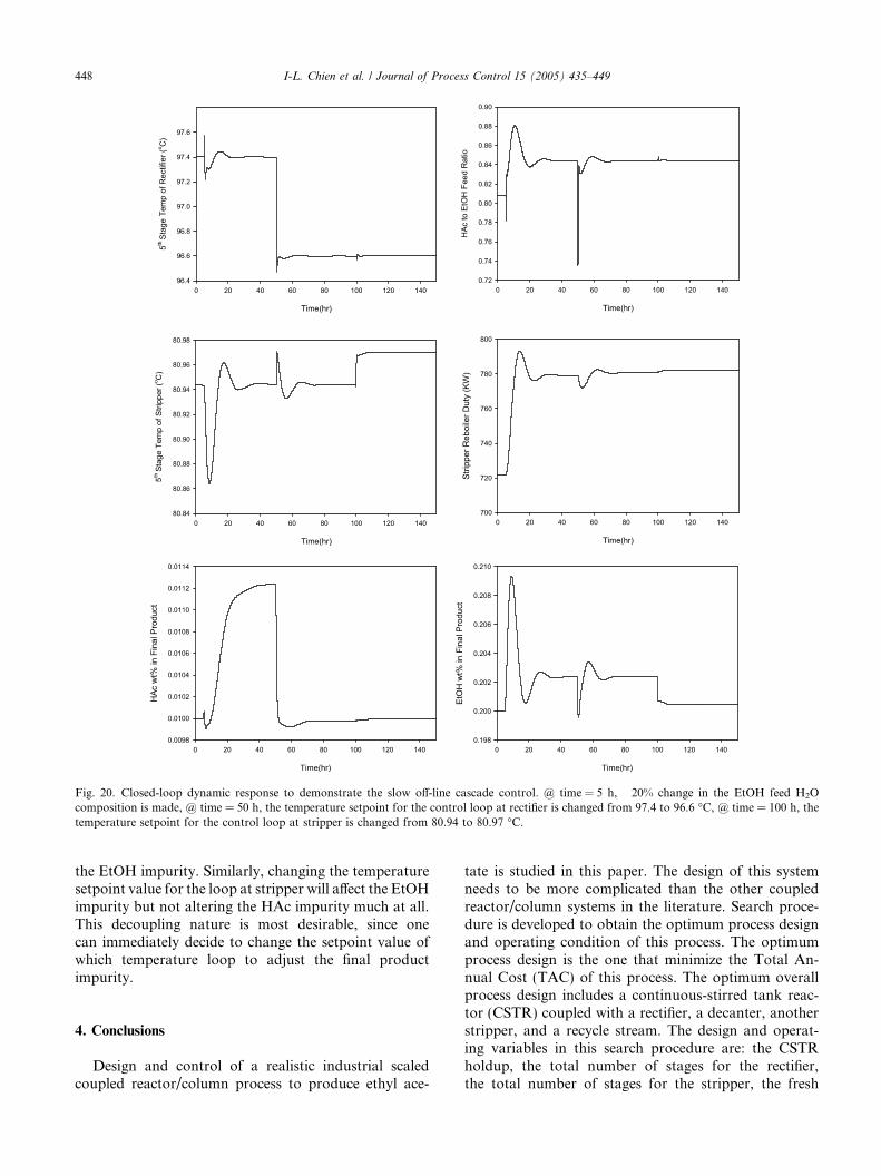
Fig. 20. Closed-loop dynamic response to demonstrate the slow off-line cascade control. @ time = 5 h, �20% change in the EtOH feed H2Ocomposition is made, @ time = 50 h, the temperature setpoint for the control loop at rectifier is changed from 97.4 to 96.6 �C, @ time = 100 h, thetemperature setpoint for the control loop at stripper is changed from 80.94 to 80.97 �C.
448 I-L. Chien et al. / Journal of Process Control 15 (2005) 435–449
the EtOH impurity. Similarly, changing the temperaturesetpoint value for the loop at stripper will affect the EtOHimpurity but not altering the HAc impurity much at all.This decoupling nature is most desirable, since onecan immediately decide to change the setpoint value ofwhich temperature loop to adjust the final productimpurity.
4. Conclusions
Design and control of a realistic industrial scaledcoupled reactor/column process to produce ethyl ace-
tate is studied in this paper. The design of this systemneeds to be more complicated than the other coupledreactor/column systems in the literature. Search proce-dure is developed to obtain the optimum process designand operating condition of this process. The optimumprocess design is the one that minimize the Total An-nual Cost (TAC) of this process. The optimum overallprocess design includes a continuous-stirred tank reac-tor (CSTR) coupled with a rectifier, a decanter, anotherstripper, and a recycle stream. The design and operat-ing variables in this search procedure are: the CSTRholdup, the total number of stages for the rectifier,the total number of stages for the stripper, the fresh
I-L. Chien et al. / Journal of Process Control 15 (2005) 435–449 449
HAc feed flow rate, and the water injection rate. Theoverall control strategy of this system is also developed.The recommended control strategy uses the ratio ofacetic acid feed rate to ethanol feed rate to controlthe 5th stage temperature of the rectifier and uses thestripper reboiler duty to control the 5th stage tempera-ture of the stripper. This simple control strategy doesnot need any on-line composition measurements. Thestringent product impurity specifications of 0.01 wt%HAc and 0.2 wt% EtOH in the EtAc product streamcan properly be held despite feed flow rate and alsofeed composition disturbances. A slow cascade outercomposition loop structure can also be implementedusing off-line composition measurements from thequality lab. This control structure has been demon-strated to be successful in eliminating small devia-tion of the product impurity compositions to theirspecifications.
Acknowledgment
This work is supported by the National ScienceCouncil of the ROC under Grant No.: NSC 91-2214-E-011-012.
References
[1] Y.A. Chang, J.D. Seader, Simulation of continuous reactivedistillation by a homotopy-continuation method, Comput. Chem.Eng. 12 (1988) 1243–1255.
[2] J. Simandl, W.Y. Svrcek, Extension of the simultaneous-solutionand inside-outside algorithms to distillation with chemical reac-tions, Comput. Chem. Eng. 15 (1991) 337–348.
[3] K. Alejski, F. Duprat, Dynamic simulation of the multicompo-nent reactive distillation, Chem. Eng. Sci. 51 (1996) 4237–4252.
[4] D.B. Keyes, Esterification processes and equipment, Ind. Eng.Chem. 24 (1932) 1096–1103.
[5] H. Bock, M. Jimoh, G. Wozny, Analysis of reactive distillationusing the esterification of acetic acid as an example, Chem. Eng.Technol. 20 (1997) 182–191.
[6] N. Vora, P. Daoutidis, Dynamic and control of an ethyl acetatereactive distillation column, Ind. Eng.Chem.Res. 40 (2001) 833–849.
[7] Y.T. Tang, H.P. Huang, I.L. Chien, Design of a complete ethylacetate reactive distillation system, J. Chem. Eng. Japan 36 (2003)1352–1363.
[8] C.K. Yi, W.L. Luyben, Design and control of coupled reactor/column systems – Part 1. A binary coupled reactor/rectifiersystem, Comput. Chem. Eng. 21 (1997) 25–46.
[9] C.K. Yi, W.L. Luyben, Design and control of coupled reactor/column systems – Part 2. more complex coupled reactor/columnsystem, Comput. Chem. Eng. 21 (1997) 47–67.
[10] C.K. Yi, W.L. Luyben, Design and control of coupled reactor/column systems – Part 3. a reactor/stripper with two columns andrecycle, Comput. Chem. Eng. 21 (1997) 69–86.
[11] S.F. Chiang, C.L. Kuo, C.C. Yu, D.S.H. Wong, Design alterna-tives for the amyl acetate process: coupled reactor/column andreactive distillation, Ind. Eng. Chem. Res 41 (2002) 3233–3246.
[12] R.J. Burkett, D. Rossiter;, Choosing the right control stucture forindustrial distillation columns, Proc. Process Control Instrument.(2000) 38–42.
[13] J.G. Hayden, J.P. O�Connell, A generalized method for predictingsecond virial coefficients, Ind. Eng. Chem. Process Des. Dev. 14(1975) 209–216.
[14] W.L. Luyben, Plantwide Dynamic Simulators in Chemi-cal Processing and Control, Marcel Dekker, Inc., New York,2002.
[15] I.L. Chien, P.S. Fruehauf, Consider IMC tuning to improvecontroller performance, Chem. Eng. Prog. 86 (1990) 33–41.