Design and Control of a Four Steered Wheeled Mobile Robot
6
Design and Control of a Four Steered Wheeled Mobile Robot Michel Lauria, Isabelle Nadeau, Pierre Lepage, Yan Morin, Patrick Giguère, Fréderic Gagnon, Dominic Létourneau and François Michaud LABORIUS - Research Laboratory on Mobile Robotics and Intelligent Systems Department of Electrical Engineering and Computer Engineering Université de Sherbrooke Sherbrooke, Québec J1K 2R1, CANADA {Michel.Lauria, Isabelle.Nadeau, Dominic.Letourneau, Francois.Michaud}@USherbrooke.ca {Pierre.Lepage, Yan.Morin, Patrick.Giguere, Frederic.Gagnon}@Robomotio.com Abstract - This paper presents the kinematical analysis of AZIMUT-2, a four steered wheeled mobile robot. The utilization of a new wheel concept called the AZIMUT wheel allowed us to create an innovative omnidirectional non-holonomic robot. Novelty of this wheel concept resides in the non-conventional positioning of the steering axis and the wheel axis. We propose a kinematical model based on the geometrical constraints of these wheels. The degree of mobility, steerability and maneuverability are studied. Additionally, we describe a special design implementation of the wheel mechanism to overcome a hyper- motorization issue inherent to the wheel’s geometrical properties. Finally, we describe AZIMUT-2’s two operational and seven locomotion modes, along with a control algorithm based on the kinematical model of the robot. I. INTRODUCTION Real world usage of mobile robotic platforms is limited primarily by the robot’s capability to move in and to perceive the world. Our objective is to design a multi-purpose robotic platform on which different locomotion modalities can be used. Designing a robot with flexible locomotion capabilities requires the integration of complex mechanical, electrical and computer components. Difficult design compromises (e.g., size versus weight versus energy versus heat dissipation versus responsiveness) must be addressed, with measurable impacts only after integrating all of the components together. It is an iterative process that requires more than just one prototype to come up with an appropriate solution to an application problem. Over the last three years, we have worked on such platform (named AZIMUT), presenting two omnidirectional and modular research prototypes [1]. They were designed to validate multi-modal locomotion capabilities, providing simple reconfigurations (done through manual interventions or even autonomously by the robot) for various usages over different kinds of environments. AZIMUT’s concept aims at versatility in the locomotion modes by combining wheels, tracks, legs, etc. into one platform. Our interest in this paper is on AZIMUT’s wheeled configuration. It has been established that the number, the nature and the disposition of the wheels determine the kinematical properties of a robot [2]. As of now, five categories of wheels have been identified: the fixed standard wheel, the steered standard wheel, the Castor wheel, the Swedish wheel and the spherical wheel. In this paper, we introduce a new category of wheel, named the AZIMUT wheel. In the following sections, we present and analyze the kinematical properties of this new wheel, and present design guidelines related for its implementation. II. PRESENTATION OF AZIMUT To conduct research activities on advanced kinematic and locomotion control of mobile robots with concrete results, real platforms are required. With the goal of designing a robotic platform combining different locomotion mechanisms and intended to operate in home-like environments, AZIMUT’s first prototype (AZ1) [1], shown in Figure 1, was designed in 2002. AZ1 is symmetrical and is made of four independent articulations. Each articulated part combines a leg, a track and Fig. 1 AZIMUT-1
Transcript of Design and Control of a Four Steered Wheeled Mobile Robot
Design and Control of a Four Steered Wheeled Mobile Robot
Michel Lauria, Isabelle Nadeau, Pierre Lepage, Yan Morin, Patrick Giguère, Fréderic Gagnon, Dominic Létourneau and François Michaud
LABORIUS - Research Laboratory on Mobile Robotics and Intelligent Systems Department of Electrical Engineering and Computer Engineering
Université de Sherbrooke Sherbrooke, Québec J1K 2R1, CANADA
{Michel.Lauria, Isabelle.Nadeau, Dominic.Letourneau, Francois.Michaud}@USherbrooke.ca {Pierre.Lepage, Yan.Morin, Patrick.Giguere, Frederic.Gagnon}@Robomotio.com
Abstract - This paper presents the kinematical analysis of
AZIMUT-2, a four steered wheeled mobile robot. The utilization of a new wheel concept called the AZIMUT wheel allowed us to create an innovative omnidirectional non-holonomic robot. Novelty of this wheel concept resides in the non-conventional positioning of the steering axis and the wheel axis. We propose a kinematical model based on the geometrical constraints of these wheels. The degree of mobility, steerability and maneuverability are studied. Additionally, we describe a special design implementation of the wheel mechanism to overcome a hyper-motorization issue inherent to the wheel’s geometrical properties. Finally, we describe AZIMUT-2’s two operational and seven locomotion modes, along with a control algorithm based on the kinematical model of the robot.
I. INTRODUCTION
Real world usage of mobile robotic platforms is limited
primarily by the robot’s capability to move in and to perceive the world. Our objective is to design a multi-purpose robotic platform on which different locomotion modalities can be used. Designing a robot with flexible locomotion capabilities requires the integration of complex mechanical, electrical and computer components. Difficult design compromises (e.g., size versus weight versus energy versus heat dissipation versus responsiveness) must be addressed, with measurable impacts only after integrating all of the components together. It is an iterative process that requires more than just one prototype to come up with an appropriate solution to an application problem. Over the last three years, we have worked on such platform (named AZIMUT), presenting two omnidirectional and modular research prototypes [1]. They were designed to validate multi-modal locomotion capabilities, providing simple reconfigurations (done through manual interventions or even autonomously by the robot) for various usages over different kinds of environments. AZIMUT’s concept aims at versatility in the locomotion modes by combining wheels, tracks, legs, etc. into one platform.
Our interest in this paper is on AZIMUT’s wheeled configuration. It has been established that the number, the nature and the disposition of the wheels determine the kinematical properties of a robot [2]. As of now, five categories of wheels have been identified: the fixed standard wheel, the steered standard wheel, the Castor wheel, the Swedish wheel and the spherical wheel. In this paper, we introduce a new category of wheel, named the AZIMUT wheel. In the following sections, we present and analyze the kinematical properties of this new wheel, and present design guidelines related for its implementation.
II. PRESENTATION OF AZIMUT
To conduct research activities on advanced kinematic and
locomotion control of mobile robots with concrete results, real platforms are required. With the goal of designing a robotic platform combining different locomotion mechanisms and intended to operate in home-like environments, AZIMUT’s first prototype (AZ1) [1], shown in Figure 1, was designed in 2002. AZ1 is symmetrical and is made of four independent articulations. Each articulated part combines a leg, a track and
Fig. 1 AZIMUT-1

a wheel, and has three degrees of freedom (DOF) (propulsion, direction and rotation). The leg can rotate 360° around its attachment point and 180° to change its direction. Once an articulation is placed at the right position, the system is designed to keep it in position without consuming electrical energy. When the articulations are stretched, the robot can move by making the tracks rotate around the legs. As the articulations move upward toward the vertical, the point of contact of the leg with the ground moves from the track to the rubber strip fixed outbound of the attachment axle of the articulation. This rubber strip creates a very narrow wheel that allows the robot to change the direction of an articulation with minimum friction. AZ1 can change direction using differential steering or by changing the direction of its articulations, making the platform omnidirectional (as represented in Fig. 2) and allowing it to move in tight areas (to handle straight or circular staircases in home environments). The robot can cross its articulations and lift itself up when it gets stuck over an obstacle. Being omnidirectional, it would also be possible for a group of AZ1 robots to change direction in a coordinated fashion while transporting together a common payload or large objects, without requiring a rotative fixture for the object to carry. Many other configurations can be imagined, and the 12 DOF on AZ1 give the robot great flexibility and versatility in its locomotion capabilities.
In 2004, we initiated the design of AZIMUT’s second
prototype (AZ2 – Fig. 3), with the goals of improving over the last design as follows: • Increased modularity is achieved by having detachable
articulations. AZ2 can be configured to use wheels, legs or tracks, or combination of them. This led to the design of a wheel-motor (made with a brushless motor coupled with a harmonic drive reducer), providing propulsion to the robot in a wheel configuration or a track configuration, lighter and more powerful than the ones used in the first prototype. Figure 4 illustrates how the wheel-motor is reused in both the wheel and the track configurations.
• Increased stability and compliance by adding a vertical suspension and using an elastic actuator for the direction of AZIMUT’s articulations. An elastic element (e.g., a
spring) is placed in the actuation mechanism and a sensor is used to measure its deformation to measure and control the forces at the actuator’s end [6], in order to improve robot motion over uneven terrains.
• The electrical and computing distributed embedded system has been improved. We now have small, stable and robust CAN modules.
• AZ2 is smaller than AZ1, lighter (33.7 kg compared to 63.5 kg) and faster (directional speed of 180°/sec compared to 120°/sec, no load; maximum velocity of 1.4 m/s compared to 1.2 m/s).
These two research prototypes provide concrete proof-of-concept demonstrations of a reconfigurable, modular and multi-modal locomotion robotic platform. AZ2 is now the platform we use to conduct our research on the topic, and real world testing of advanced kinematic and locomotion control of mobile robots, as we address in the following sections.
III. KINEMATIC ANALYSIS AND CONSTRAINTS
As a first object of study on AZ2, our interest is on its
omnidirectional kinematic model, and more specifically on the AZIMUT wheel. The AZIMUT wheel is similar to a Castor wheel. The main difference consists in the orientation of the wheel plane. With a Castor wheel, the plane of the wheel contains also the steering axis, while the AZIMUT wheel plane is parallel to the steering axis but does not contain it. In addition, the steering axis and the wheel axis intersect in one point, as shown in Fig. 5.
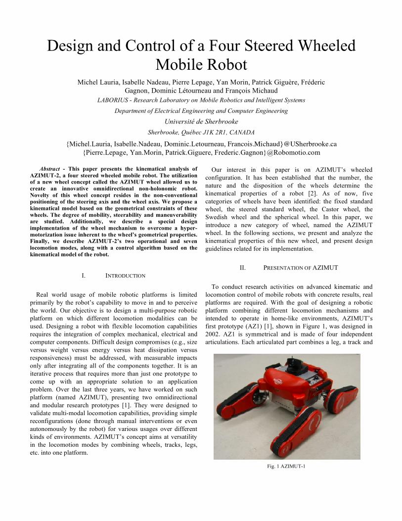
AZIMUT’s four steering axis of the wheels are located at the
corners of a square. The steering angle range of each wheel is limited to
!
180o . For example, wheel number 1 can steer from
!
"45o to
!
135o . Its steering range comprises the full first
quadrant and one half of the adjacent quadrants two and four,
Fig. 2 AZIMUT omnidirectional capabilities.
Fig. 3 AZIMUT-2 subsystems.
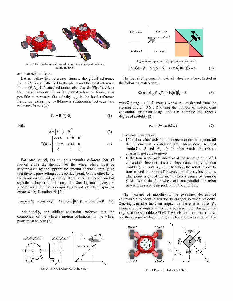
as illustrated in Fig. 6. Let us define two reference frames: the global reference
frame
!
{O,XI,YI}attached to the plane, and the local reference
frame
!
{P,XR,YR} attached to the robot chassis (Fig. 7). Given
the chassis velocity
!
˙ " I in the global reference frame, it is
possible to represent the velocity
!
˙ " R
in the local reference frame by using the well-known relationship between two reference frames [3]:
!
˙ " R
= R #( ) $ ˙ " I (1)
with:
!
˙ " = ˙ x ˙ y ˙ # [ ]T
(2)
!
R "( ) =
cos" sin" 0
#sin" cos" 0
0 0 1
$
%
& & &
'
(
) ) )
(3)
For each wheel, the rolling constraint enforces that all
motion along the direction of the wheel plane must be accompanied by the appropriate amount of wheel spin
!
˙ " so that there is pure rolling at the contact point. On the other hand, the non-conventional geometry of the steering mechanism has significant impact on this constraint. Steering must always be accompanied by the appropriate amount of wheel spin, as expressed by Equation (4) [2]:
!
sin " + #( ) $ cos " + #( ) d + l cos#[ ]R %( ) ˙ & I$ r ˙ ' + d ˙ # = 0 (4)
Additionally, the sliding constraint enforces that the
component of the wheel’s motion orthogonal to the wheel plane must be zero [2]:
!
cos " + #( ) sin " + #( ) l sin#[ ]R $( ) ˙ % I
= 0 (5) The four sliding constraints of all wheels can be collected in
the following matrix form:
!
C "1,"2,"3,"4( ) #R $( ) ˙ %
I= 0 (6)
with
!
C being a
!
4 " 3( ) matrix whose values depend from the steering angles
!
"i(t). Knowing the number of independent
constraints instantaneously, one can compute the robot’s degree of mobility [2]:
!
"m
= 3# rank(C) (7) Two cases can occur:
1. If the four wheel axis do not intersect at the same point, all the kinematical constraints are independent, so that
!
rank(C) = 3 and
!
"m
= 0 . In other words, the robot’s chassis is not able to move.
2. If the four wheel axis intersect at the same point, 3 of 4 constraints become linearly dependant, implying that
!
rank(C) = 2 and
!
"m
=1. Therefore, the robot is able to turn around the point of intersection of the wheel’s axis. This point is called the instantaneous centre of rotation (ICR). When the four wheel axis are parallel, the robot moves along a straight path with ICR at infinity.
The measure of mobility above examines degrees of
controllable freedom in relation to changes to wheel velocity. Steering can also have an impact on the chassis pose
!
"I.
However, this impact is indirect because after changing the angles of the steerable AZIMUT wheels, the robot must move for the change in steering angle to have impact on pose. The
Fig. 4 The wheel-motor is reused in both the wheel and the track
configurations.
Fig. 6 Wheel quadrants and physical constraints.
Fig. 5 AZIMUT wheel CAD drawings.
Fig. 7 Four wheeled AZIMUT-2.

number of independently controllable steering parameters (called degree of steerability [2]) is given by:
!
"s
= rank(C) (8) Two cases can occur:
1. If the four wheel axis do not intersect at the same point, the degree of steerability is not defined.
2. If the four wheel axis intersect at the same point,
!
rank(C) = 2 and
!
"s
= 2 . This result implies that the robot can place its ICR anywhere on the ground plane.
The degree of maneuverability [2] is given by Equation (9).
This means that the configuration space of AZ2’s chassis is 3.
!
"M
= "m
+"s
=1+ 2 = 3 (9)
IV. COMPUTING THE ADMISSIBLE VELOCITY SPACE
Our interest in this section is to study the different ways in
which the robot can use its controllable degrees of freedom to position itself in the environment. Considering that the configuration space of the robot’s chassis is three, we will care about how the robot is able to move between various configurations. The computation of admissible velocity space is the first step in understanding how a robot can move from configurations space’s position A to position B. Using a method described in [4], we define a vector
!
v containing: • The linear velocities of the four wheel-ground contact
points. • The linear velocities of the four points situated on the
four steering axis. • The linear velocity of the chassis’s centre. • The angular velocity of the chassis. • Then angular velocities of the arms connecting the
wheels. The rigid body constraint equations applied to the chassis
and the four arms, plus the sliding constraint equations applied to the four wheels, can be written in a compact matrix form:
!
G "v = 0 (10) Using linear algebra, it can be said that the null space
!
G provides a base of the admissible velocity workspace. In other words, any velocity state can be expressed by Equation (11):
!
v = null(G) "p (11) Using this results: 1. If the wheel axis does not intersect at the same point, the
dimension of the admissible velocity space is 4. The
chassis cannot move while the four arms can move independently driven by parameter’s vector
!
p[4 "1]. 2. If the four wheel axis intersect at the same point, the
dimension of the admissible velocity space is 5. The chassis can turn around the ICR and the four arms can move independently. The velocity vector is defined by choosing the parameters of
!
p[5"1] . That means that ICR’s position relative to the chassis can be changed while the robot is moving.
Fig. 8 illustrates the simulator implemented to visualize the
velocity state vector graphically. This tool allows the user to define the free kinematical parameters and the ICR’s position as inputs and visualize the corresponding velocity state as output.
V. EFFECTS OF THE STEERING ANGLES LIMITATIONS ON THE VELOCITIES ADMISSIBLE SUBSPACES
We discovered that the resulting admissible velocity space
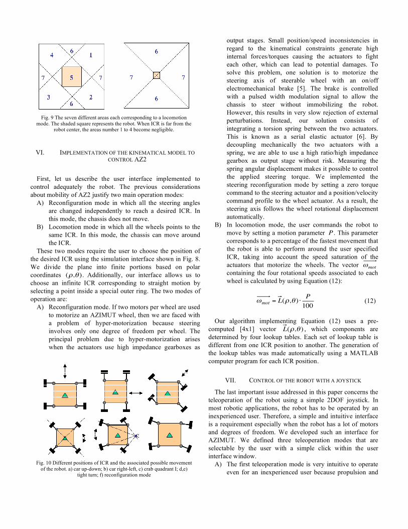
consists of the addition of eight subspaces that touches each other in one point at the origin of the total space. One subspace corresponds to the steering reconfiguration mode while the others can be visualized graphically by decomposing the plane into seven areas (shown in Fig. 9). For each area, the ICR can be smoothly displaced without having to immobilize the robot. These seven zones define the seven locomotion modes of the robot, illustrated in Fig. 10: 1) crab quadrant I; 2) crab quadrant IV; 3) crab quadrant III; 4) crab quadrant II; 5) tight turn; 6) car right-left; 7) car up-down.
In theory, the same ICR position could be obtained with
!
24
=16 combinations of arm placements. This is due to the fact that a given ICR position can be pointed by each arm with two theoretical steering angles,
!
" and
!
" +180o . Due to the
mechanical implementation of the AZIMUT wheel, some physical constraints have been added and most combinations become invalid.
Fig. 8 Simulation interface screenshot. User can select an ICR and the program computes the velocities of the wheels. Note the infinite outer
ring that corresponds to straight motion of the chassis.
VI. IMPLEMENTATION OF THE KINEMATICAL MODEL TO CONTROL AZ2
First, let us describe the user interface implemented to
control adequately the robot. The previous considerations about mobility of AZ2 justify two main operation modes:
A) Reconfiguration mode in which all the steering angles are changed independently to reach a desired ICR. In this mode, the chassis does not move.
B) Locomotion mode in which all the wheels points to the same ICR. In this mode, the chassis can move around the ICR.
These two modes require the user to choose the position of the desired ICR using the simulation interface shown in Fig. 8. We divide the plane into finite portions based on polar coordinates
!
(",# ) . Additionally, our interface allows us to choose an infinite ICR corresponding to straight motion by selecting a point inside a special outer ring. The two modes of operation are:
A) Reconfiguration mode. If two motors per wheel are used to motorize an AZIMUT wheel, then we are faced with a problem of hyper-motorization because steering involves only one degree of freedom per wheel. The principal problem due to hyper-motorization arises when the actuators use high impedance gearboxes as
output stages. Small position/speed inconsistencies in regard to the kinematical constraints generate high internal forces/torques causing the actuators to fight each other, which can lead to potential damages. To solve this problem, one solution is to motorize the steering axis of steerable wheel with an on/off electromechanical brake [5]. The brake is controlled with a pulsed width modulation signal to allow the chassis to steer without immobilizing the robot. However, this results in very slow rejection of external perturbations. Instead, our solution consists of integrating a torsion spring between the two actuators. This is known as a serial elastic actuator [6]. By decoupling mechanically the two actuators with a spring, we are able to use a high ratio/high impedance gearbox as output stage without risk. Measuring the spring angular displacement makes it possible to control the applied steering torque. We implemented the steering reconfiguration mode by setting a zero torque command to the steering actuator and a position/velocity command profile to the wheel actuator. As a result, the steering axis follows the wheel rotational displacement automatically.
B) In locomotion mode, the user commands the robot to move by setting a motion parameter
!
P . This parameter corresponds to a percentage of the fastest movement that the robot is able to perform around the user specified ICR, taking into account the speed saturation of the actuators that motorize the wheels. The vector
!
"mot
containing the four rotational speeds associated to each wheel is calculated by using Equation (12):
!
"mot
= L(#,$ ) %P
100 (12)
Our algorithm implementing Equation (12) uses a pre-
computed [4x1] vector
!
L(",# ) , which components are determined by four lookup tables. Each set of lookup table is different from one ICR position to another. The generation of the lookup tables was made automatically using a MATLAB computer program for each ICR position.
VII. CONTROL OF THE ROBOT WITH A JOYSTICK
The last important issue addressed in this paper concerns the teleoperation of the robot using a simple 2DOF joystick. In most robotic applications, the robot has to be operated by an inexperienced user. Therefore, a simple and intuitive interface is a requirement especially when the robot has a lot of motors and degrees of freedom. We developed such an interface for AZIMUT. We defined three teleoperation modes that are selectable by the user with a simple click within the user interface window.
A) The first teleoperation mode is very intuitive to operate even for an inexperienced user because propulsion and
Fig. 9 The seven different areas each corresponding to a locomotion
mode. The shaded square represents the robot. When ICR is far from the robot center, the areas number 1 to 4 become negligible.
Fig. 10 Different positions of ICR and the associated possible movement
of the robot. a) car up-down; b) car right-left, c) crab quadrant I; d,e) tight turn; f) reconfiguration mode
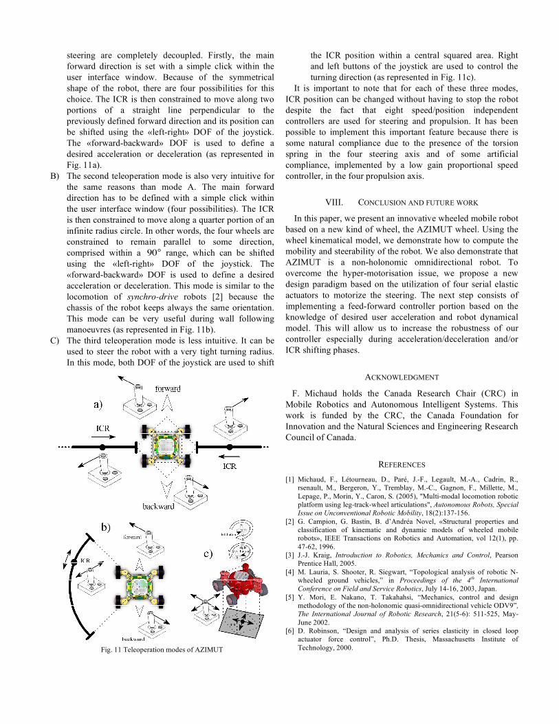
steering are completely decoupled. Firstly, the main forward direction is set with a simple click within the user interface window. Because of the symmetrical shape of the robot, there are four possibilities for this choice. The ICR is then constrained to move along two portions of a straight line perpendicular to the previously defined forward direction and its position can be shifted using the «left-right» DOF of the joystick. The «forward-backward» DOF is used to define a desired acceleration or deceleration (as represented in Fig. 11a).
B) The second teleoperation mode is also very intuitive for the same reasons than mode A. The main forward direction has to be defined with a simple click within the user interface window (four possibilities). The ICR is then constrained to move along a quarter portion of an infinite radius circle. In other words, the four wheels are constrained to remain parallel to some direction, comprised within a
!
90° range, which can be shifted using the «left-right» DOF of the joystick. The «forward-backward» DOF is used to define a desired acceleration or deceleration. This mode is similar to the locomotion of synchro-drive robots [2] because the chassis of the robot keeps always the same orientation. This mode can be very useful during wall following manoeuvres (as represented in Fig. 11b).
C) The third teleoperation mode is less intuitive. It can be used to steer the robot with a very tight turning radius. In this mode, both DOF of the joystick are used to shift
the ICR position within a central squared area. Right and left buttons of the joystick are used to control the turning direction (as represented in Fig. 11c).
It is important to note that for each of these three modes, ICR position can be changed without having to stop the robot despite the fact that eight speed/position independent controllers are used for steering and propulsion. It has been possible to implement this important feature because there is some natural compliance due to the presence of the torsion spring in the four steering axis and of some artificial compliance, implemented by a low gain proportional speed controller, in the four propulsion axis.
VIII. CONCLUSION AND FUTURE WORK
In this paper, we present an innovative wheeled mobile robot based on a new kind of wheel, the AZIMUT wheel. Using the wheel kinematical model, we demonstrate how to compute the mobility and steerability of the robot. We also demonstrate that AZIMUT is a non-holonomic omnidirectional robot. To overcome the hyper-motorisation issue, we propose a new design paradigm based on the utilization of four serial elastic actuators to motorize the steering. The next step consists of implementing a feed-forward controller portion based on the knowledge of desired user acceleration and robot dynamical model. This will allow us to increase the robustness of our controller especially during acceleration/deceleration and/or ICR shifting phases.
ACKNOWLEDGMENT
F. Michaud holds the Canada Research Chair (CRC) in Mobile Robotics and Autonomous Intelligent Systems. This work is funded by the CRC, the Canada Foundation for Innovation and the Natural Sciences and Engineering Research Council of Canada.
REFERENCES [1] Michaud, F., Létourneau, D., Paré, J.-F., Legault, M.-A., Cadrin, R.,
rsenault, M., Bergeron, Y., Tremblay, M.-C., Gagnon, F., Millette, M., Lepage, P., Morin, Y., Caron, S. (2005), "Multi-modal locomotion robotic platform using leg-track-wheel articulations", Autonomous Robots, Special Issue on Unconventional Robotic Mobility, 18(2):137-156.
[2] G. Campion, G. Bastin, B. d’Andréa Novel, «Structural properties and classification of kinematic and dynamic models of wheeled mobile robots», IEEE Transactions on Robotics and Automation, vol 12(1), pp. 47-62, 1996.
[3] J.-J. Kraig, Introduction to Robotics, Mechanics and Control, Pearson Prentice Hall, 2005.
[4] M. Lauria, S. Shooter, R. Siegwart, “Topological analysis of robotic N-wheeled ground vehicles,” in Proceedings of the 4th International Conference on Field and Service Robotics, July 14-16, 2003, Japan.
[5] Y. Mori, E. Nakano, T. Takahahsi, “Mechanics, control and design methodology of the non-holonomic quasi-omnidirectional vehicle ODV9”, The International Journal of Robotic Research, 21(5-6): 511-525, May-June 2002.
[6] D. Robinson, “Design and analysis of series elasticity in closed loop actuator force control”, Ph.D. Thesis, Massachusetts Institute of Technology, 2000.
Fig. 11 Teleoperation modes of AZIMUT