Enabling Tactical Autonomy for Unmanned Surface Vehicles ...

Lehigh UniversityLehigh Preserve
Theses and Dissertations
2015
Design and Construction of Unmanned SurfaceVehiclesScott LarsonLehigh University
Follow this and additional works at: http://preserve.lehigh.edu/etd
Part of the Mechanical Engineering Commons
This Thesis is brought to you for free and open access by Lehigh Preserve. It has been accepted for inclusion in Theses and Dissertations by anauthorized administrator of Lehigh Preserve. For more information, please contact [email protected].
Recommended CitationLarson, Scott, "Design and Construction of Unmanned Surface Vehicles" (2015). Theses and Dissertations. 2675.http://preserve.lehigh.edu/etd/2675

Design and Construction of Unmanned Surface Vehicles
By
Scott Nils Larson
A Thesis
Presented to the Graduate and Research Committee
Of Lehigh University
In Candidacy for the Degree of
Master of Science
in
Mechanical Engineering and Mechanics
Lehigh University
May 2015

ii
Copyright by Scott Nils Larson
2015

iii
This thesis is accepted and approved in partial fulfillment of the requirements for
the Master of Science.
____________________________
Date
___________________________________
Joachim L. Grenestedt, Thesis Advisor
__________________________________
Gary Harlow, Chair
Department of Mechanical Engineering and Mechanics

iv
Acknowledgements
My faculty advisor Joachim Grenestedt has guided me through the process of
learning to design and build traditional and composite structures, ensuring that my
education is relevant and well rounded. Without his direction there would be no USV
project and I would not have accomplished what I have in the last two years. My work
was also made possible on a daily basis through the support of the other members of the
Lehigh University Composites Laboratory. Robert Thodal and Jacob Patterson spent
many days with me in the laboratory demonstrating best practices for working with
composite materials, hand tools and machine tools. They were always available to help
when another hand was needed. Thanks as well to Bill Maroun for his instruction and
support in using the water jet cutter, my most heavily utilized resource in the
construction of the boats. Bill also made time to listen to ideas and give suggestions for
engineering problems.
Special thanks also to Eli Towne who spent countless hours teaching me to use
the CNC mill, manual mill, lathe and other shop tools. With his help I safely constructed
numerous quality pieces of hardware. Thanks also to Dick Towne for his support in the
use of his machine shop.

v
Table of Contents Acknowledgements .............................................................................................................. iv
List of Figures ...................................................................................................................... vii
List of Equations .................................................................................................................... x
Abstract ................................................................................................................................ 1
Background .......................................................................................................................... 2
The LORCA Design Concept.................................................................................................. 4
Design and Construction of the LORCA Shell ....................................................................... 6
Designing the Hull ............................................................................................................ 6
Design of Self-Righting Analysis Code .............................................................................. 7
Development of LORCA Deck Shape .............................................................................. 11
Configuring the Access Hatch ........................................................................................ 13
Design of the LORCA Hull Molds .................................................................................... 14
Machining the LORCA Hull Molds .................................................................................. 15
Design and Construction of Internal Components ............................................................ 17
Motor Assembly ............................................................................................................. 19
Making the Plate Components .................................................................................. 20
Designing the Motor Mount Mold ............................................................................. 20

vi
Making the Motor Mount Mold ................................................................................ 22
Heating the Motor Mount Mold ................................................................................ 24
Designing the Battery Tray Molds .................................................................................. 26
Molding the Motor Mounts and Battery Trays .............................................................. 28
Trimming Battery Trays and Motor Mounts .................................................................. 32
Outfitting of the LORCAs .................................................................................................... 34
Modifications to the Shell .............................................................................................. 34
Installing the Drive Train and Motor Mount .................................................................. 36
Installing the Cooling System ......................................................................................... 39
Bonding the Mounting Studs ......................................................................................... 40
Installing the Electrical System ...................................................................................... 41
Testing ................................................................................................................................ 42
Additional Project: The JetStreamer Motor Pod ............................................................... 44
Future Work ....................................................................................................................... 48
Vita ..................................................................................................................................... 49

vii
List of Figures
Figure 1: LORCA Model ........................................................................................................ 6
Figure 2: LORCA Potential Energy Map ................................................................................ 9
Figure 3: Sample Output from CGHeightSingle ................................................................. 10
Figure 4: Lorca Hull ............................................................................................................ 11
Figure 5: Lorca Deck Defining Geometry ........................................................................... 12
Figure 6: LORCA Deck Cross Sections ................................................................................. 12
Figure 7: Machining LORCA Hull Plug ................................................................................ 15
Figure 8: Completed LORCA Mold Plugs ............................................................................ 16
Figure 9: LORCA Internal Components .............................................................................. 17
Figure 10: LORCA Rear Components .................................................................................. 18
Figure 11: LORCA Forward Components ........................................................................... 18
Figure 12: Motor Mount Assembly .................................................................................... 20
Figure 13: Motor Mount .................................................................................................... 21
Figure 14: Motor Mount Side Profiling Operation ............................................................. 22
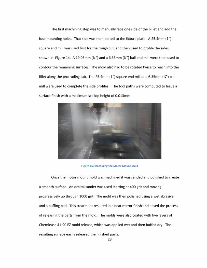
Figure 15: Machining the Motor Mount Mold .................................................................. 23
Figure 16: Finished Motor Mount Mold ............................................................................ 24
Figure 17: Minimum Cure Time vs Temperature for a 2mm SE 84LV Laminate ............... 25
Figure 18: Battery Tray Molds ............................................................................................ 27
Figure 19: Solidworks Thermal Simulation of the Battery Tray Mold................................ 28

viii
Figure 20: Motor Mount Ply Patterns ................................................................................ 28
Figure 21: Laying Pre-Preg onto Battery Tray Molds ......................................................... 29
Figure 22: Battery Tray Mold Wrapped with Peel Ply, Breather ....................................... 30
Figure 23: Two Molds Sitting under Vacuum ..................................................................... 30
Figure 24: Recorded Motor Mount Cure ........................................................................... 31
Figure 25: Battery Tray Being Trimmed ............................................................................. 33
Figure 26: Battery Trays Before and After Trimming ......................................................... 33
Figure 27: Hole Patterns on a LORCA Hull ......................................................................... 35
Figure 28: LORCA with Drive Train and Rudder Clearance Holes ...................................... 35
Figure 29: Access Hatch Lip ................................................................................................ 36
Figure 30: Bonded LORCA Motor Mount ........................................................................... 37
Figure 31: Drive Shaft Supports and Rudder Post Bonded in Place ................................... 38
Figure 32: Drive Train Components ................................................................................... 38
Figure 33: Water Pickup ..................................................................................................... 39
Figure 34: Bonding Mounting Studs for Battery Trays ...................................................... 40
Figure 35: Looking Forward at Assembled LORCA ............................................................. 41
Figure 36: Looking Aft at Assembled LORCA...................................................................... 41
Figure 37: LORCA Pond Testing .......................................................................................... 42
Figure 38: Motor Pod CAD Model ...................................................................................... 44
Figure 39: Motor Pod Mold Blank and Machined ............................................................. 45
Figure 40: Jetstreamer Motor Pod Mold ........................................................................... 46

ix
Figure 41: Jetstreamer Motor Pod Mold Half .................................................................... 46
Figure 42: Jetstreamer Motor Pod ..................................................................................... 47
Figure 43: Jetstreamer Motor Pod ..................................................................................... 47

x
List of Equations
(1) ......................................................................................................................................... 8
(2) ....................................................................................................................................... 25
(3) ....................................................................................................................................... 25
(4) ....................................................................................................................................... 27

1
Abstract
The Lehigh Ocean Research Craft Autonomous, or LORCA, was designed and built
at Lehigh University’s Composites Laboratory as a versatile unmanned boat, or
Unmanned Surface Vehicle (USV). Ten 1.2m long boats have been built in various
configurations, with the last seven built identically. The boat is fully self-righting with an
enclosed electric motor, allowing it to be deployed in ocean conditions and rolled over
without losing power or damaging equipment. Composite materials were used wherever
possible in construction resulting in a craft that is strong, fast, and lightweight.
The LORCA platform is unique in its combination of high speed, measured at over
21m/s in flat conditions, and capability of operating in ocean waves. Typically boats with
these capabilities are significantly larger and require trailers and infrastructure to launch.
Weighing less than 12kg our craft is man-portable and can be launched nearly anywhere.
Construction of the craft is currently being completed and testing of the autonomous
algorithms is underway.

2
Background
The continually increasing affordability and portability of computing power has
paved the way for the rapid development unmanned, autonomous vehicles. In the air,
on sea and on land new types of vehicles are possible now that they are no longer
limited by the requirement of carrying a driver. Unmanned vehicles can be designed to
operate at accelerations and shock loading that exceed human limits, and can be
deployed for extended periods of time while consuming minimal resources.
Autonomous boats, or Unmanned Surface Vehicles (USVs), are already being put to use
collecting hydrographic data, but there is still much room for development of more
advanced platforms.
The eventual success of USV platforms will hinge on both the physical systems
and the software that control them. One of these areas of advancement in software that
researchers at Lehigh University would like to study is the coordinated movement of a
fleet of boats, known as swarming. While the computer algorithms that control these
vehicles may be simulated, they must ultimately be tested in the real world to prove
their efficacy. Initial testing can be done on land, but does not replicate the complexity
of a dynamic ocean environment.
Many USVs exist today in forms ranging from small hobby boats to larger
experimental military craft, but presumably none offer the combination of features
desired by our lab for testing. The hobby boats are generally the smallest and lowest
cost unmanned platforms available, commonly measuring less than 1m long. These
boats are very portable, designed to be carried and deployed by hand, but are designed

3
primarily for flat lake and pond conditions. They are generally not self-righting, are not
very reliable, easily damaged, and do not have the extra space necessary for mounting
electronics. Larger platforms exist that are designed for the ocean, but are comparably
very expensive to build and operate. Our lab set out to design a USV platform that was
small, fast, and fully self-righting for operating in ocean conditions.

4
The LORCA Design Concept
The Lehigh University Composites Lab has developed the Lehigh Ocean Research
Craft Autonomous, or LORCA. This platform is designed to be robust enough for ocean
deployment, while small enough to be launched by hand. Due to its simplicity and small
size, the LORCA is inexpensive enough that a fleet of ten boats can be built, stored and
maintained on a reasonable budget. To help keep down cost and development time a
number of standard hobby components are used on the LORCA, such as the motor,
propeller, speed controller and rudder servo. The LORCA platform is fast, designed to
reach peak speeds in excess of 20m/s, so it may be deployed from shore and quickly
reach a testing area.
The LORCA deck and hull are made as a single piece carbon fiber shell. The deck
is domed so that the system is self-righting, and has only one small hatch for accessing
internal components. This design is stiff, light, and easily made water-tight for operating
in ocean conditions. The boats are outfitted with batteries and an electric motor,
eliminating the need for an air intake or exhaust. The electric motor drives a straight
drive shaft and a single, fully submerged propeller. The direction of the boat is
controlled by a spade rudder, operated inside the boat by a servo. Initially controlled
remotely by a human for testing, the LORCA platform is outfitted with an autonomous
control system and sensors. Seven boats are made to this configuration.
Three other configurations have been built using the same shell with some
different components. One design is nearly identical, but with the propeller and rudder
shifted as far towards the stern as possible. Another design utilizes two outboard

5
motors. These outboards are mounted on the transom of the LORCA shell. The last
configuration utilizes a surface-piercing propeller mounted behind the LORCA. These
configurations were built by Grenestedt and will not be covered in detail in this Thesis.

6
Design and Construction of the LORCA Shell
The LORCA shell is a single piece hull and deck with a small access hatch. The hull
was designed by Grenestedt to suite our needs for speed and cargo capacity. Software
was then written to aid in the design of a self-righting deck. This software was
successfully used to create a shape that is self-righting, but is also aerodynamically
shaped for reasonably low drag at high speeds. After the design was completed, plugs
for the hull and deck were cut at Lehigh University and sent to Marstrom Composite AB,
who made a carbon fiber mold and 10 shells. These shells were shipped back to Lehigh
for trimming and installation of internal components.
Figure 1: LORCA Model
Designing the Hull
The overall size and shape of the hull was chosen by Grenestedt as a size that is
large enough to carry all future electronics, but still small enough to use standard hobby
components. Model racing boats are commonly about 1m long, and Grenestedt
extended that length to 1.2m for additional cargo capacity. A stepped hull was used to

7
create a boat that is efficient to operate over a wide range of center of gravity by
creating a relatively large angle of attack for all running surfaces while the boat runs flat
in the water. These features are expected to make the LORCA platform versatile and
reconfigurable in the future.
Design of Self-Righting Analysis Code
Numerical computer simulations can be used to quickly determine the stability of
a boat independent of the specific geometry. Commercially available marine design
software packages were researched in hopes of finding suitable software, but all fell
short. Packages such as DELFTship™ only simulate stability about the longitudinal axis to
±90° of rotation. While this may be suitable for most vessels, LORCA is designed to
recover from any angle of rotation. For this reason custom code was developed to
calculate the hydrostatic stability of the craft.
The stability analysis code used in the design of LORCA was based upon code
written in FORTRAN by Grenestedt. Grenestedt's program reads in an STL file for any
solid body, and calculates the buoyancy point of the solid body immersed in still water at
any angle of rotation. This is done by first rotating the part to a desired angle of pitch
and roll. Holding this orientation constant the craft is moved vertically in and out of the
water. The secant method is used to converge on the buoyancy point, where the mass
of the displaced water is equal to the mass of the boat. At this point the normal force is
equal to the weight of the craft, the shear forces are zero, and the reaction moments
may be nonzero and are calculated. This code by Grenestedt forms the core

8
functionality of the stability code, though further development was desired to use this
information to predict the stability of the craft.
The self-righting capability of the LORCA was designed only as a recovery
mechanism, and it was therefore sufficient to only consider the static stability of the
craft. If the boat were to flip or tumble, power to the propeller will be eliminated and
sufficient time may be allowed for the craft to reach a fully righted state. For the static
case the stability of the system can be directly determined from its potential energy. Any
local minima in the potential energy across the full range of pitch and roll are considered
to be stable points, and should therefore be avoided. Ideally the LORCA will have only
one stable point in the upright position. Treating the system as a rigid body the potential
energy is simply:
𝑃𝐸 = 𝑚𝑔ℎ (1)
where m is the mass, g is the acceleration due to gravity, h is the height of the center of
gravity of the craft.
To extrapolate static stability of the craft, three different tools were built around
this code in FORTRAN. The first tool, CGHeight, calculates the potential energy at points
evenly distributed across all angled of pitch and roll of the craft for a single CG location
and mass. Two rotations about fixed axes were applied to analyze the craft. With the
boat aligned with the bow to the north, the boat is first turned clockwise to the east at
an angle θ. The boat is then rotated about the east-west axis at an angle φ. Results
were input into MATLAB and plotted as a three dimensional graph, as shown in Figure 2.

9
Figure 2: LORCA Potential Energy Map
Visualization of the data provided a means of quickly identifying orientations that
were stable. The peaks in Figure 2 show a high potential associated with the boat when
it is balanced vertically with either the bow or stern in the water. In these orientations
the center of gravity is highest off the water. The lowest potential energy is at θ=0,
corresponding to the boat in its intended upright position. This visualization would also
show the location of any energy wells if present, and directly communicate their shape
and size.

10
A second tool, CGHeightBatch, runs this code for a discrete range of center of
gravity and mass, allowing for a more thorough analysis of a particular geometry. To
handle analysis of the much larger data set produced by this program, code was written
to discretely determine local minima within the data set. Local minima are determined
to be the points that have no lower potential energy in the surrounding 8 data points of
the array. To quantitatively evaluate the severity of each minimum, another portion of
code was written to find the next closest point with a lower energy and display the
angular distance between the points. If significant minima were found, the first tool
could be called up to the specific mass and CG for further analysis.
Part of Grenestedt’s code was isolated as a third tool, CGHeightSingle, which
outputs the portion of the solid geometry that is submerged in water for a specific
rotation, mass, and CG. This produces an STL file that can be viewed in solidworks.
Knowing which portion of the boat is wetted at a stability point provided insight into
what to change to improve stability. Figure 3 below shows a sample output for a local
stability point in an early version of the LORCA. This is the part of the rear deck that
would be under water for an 11kg boat rolled upside down.
Figure 3: Sample Output from CGHeightSingle

11
Development of LORCA Deck Shape
Once a set of visual and quantitative tools were created for analyzing the 3D
stability of a solid geometry, the actual shape of the LORCA platform was designed. The
hull to which the deck is attached was designed by Grenestedt as shown in Figure 4.
Figure 4: Lorca Hull
A deck was added on top, starting from a spherical cap in the bow and returning
to a low profile in the stern. Ellipses were used to form six cross sections where angle at
the parting plane and midpoint height were variables in a design table. The cross
sections were then lofted into a smooth deck shape that comes to a sharp corner at the
stern. The origin of the boat coordinate system is the intersection of the parting plane,
the stern plane and the centerline. In this coordinate system the Y-axis is up, the X-axis is
left, and the Z-axis is forward, shown in Figure 5.

12
Figure 5: Lorca Deck Defining Geometry
Figure 6: LORCA Deck Cross Sections
In order to calculate the stability of the craft assumptions were made for the
location of the center of gravity. For simplicity the center of gravity was assumed to be
along the Y-Z plane. The center of gravity was also assumed to be along the parting
plane, a height of Y=0, which is a conservative assumption given most internal

13
components will be mounted below this point. From a summation of the main internal
components the CG of the fully constructed boat was predicted to fall in the range
Z=[400mm, 550mm] from the stern. The mass was expected to range from 7kg to 15kg
depending on the number of batteries and electronics used.
An initial estimate of a self-righting shape was designed with aerodynamics in
mind. Testing with the software tools created revealed multiple stability points,
primarily when the craft was fully upside down, tilted towards the stern. The shape of
the hull was expanded in some places and reduced in others to eliminate any local
minima of the potential energy.
This process of simulation and adjustment was iterated until the design was
stable in only the upright position for the proposed range of center of gravity and mass.
Some shallow energy wells were considered acceptable since the boat will have
disturbances in a real world environment. The remaining minima had activation energies
that were found by inspection to be on the order of one percent of the available
potential energy. These local minima are not expected to be an issue in real world
dynamic conditions.
Configuring the Access Hatch
Another important feature of the LORCA is for its watertight seal for deployment
in ocean conditions. Many boats of this size have decks that are removable to allow for
access to internal components. To achieve the best strength and water seal, the inside
of the LORCA is accessible only through a single hatch on the port side. The internal
components that were accessed for construction and later use range from the stern to

14
the motor mount 800mm forward. For best ease of access the hatch was located
between 250mm and 450mm forward. The size was kept as small as possible while still
allowing the largest internal component, the motor mount assembly, to be inserted. A
15mm lip around the hole was recessed 5mm deep to allow a hatch cover to sit flush
against the outer hull. Using a small access hatch will increase assembly time, but
ultimately produced a stronger and more seaworthy boat.
Design of the LORCA Hull Molds
The LORCA was designed to be molded out of carbon fiber reinforced composite,
allowing for a single piece shell that contains the complex geometry of the hull and deck
without compromising on weight or strength. The outer shell serves as the full structure
of the boat, and all internal and external components are mounted to the shell.
The geometry of the LORCA shell is well suited for a two part mold female mold.
Using a female mold allows for the critical outer surface to have the best surface finish
and the highest tolerance of the part. Peel-ply may then be used on the inside to provide
easier bonding of internal components. The plane between the hull and the deck
provides a natural parting plane for the mold. Minor changes were made to the stern
and the steps in the hull to remove undercuts that would have impeded the removal of
the finished part from the mold. Removing these undercuts only required the angle of
the stern plane to be rotated about 3° and should have negligible effects on the
performance of the boat. Two plugs were created with flanges on all four sides, and
cylindrical alignment grooves to allow for the insertion of 9.25mm (3/8”) dowel pins.

15
Machining the LORCA Hull Molds
The mold plugs were machined from a block of epoxy tooling board using the
Lehigh Composite Lab’s Hendrick 5-axis router. NX Manufacturing was used as the CAM
software to create the tool paths and output machine G-code. A custom post was
written to configure the CAM software to output the proper G-code for the CNC machine
controller. Roughing was done with a 25.4mm (1”) square end mill, and surface profiling
was done with both a 25.4mm (1”) ball end mill and a 9.25mm (3/8”) ball end mill.
Styrofoam was used as a test material to validate the code on the router, and a few
minor issues were found and eliminated. The finished plugs were loaded into a crate and
packed with foam for transport to Marstrom Composite AB. Marstrom was contracted
to use the plugs to make a carbon fiber mold, and then 10 LORCA shells.
Figure 7: Machining LORCA Hull Plug

16
Figure 8: Completed LORCA Mold Plugs

17
Design and Construction of Internal Components
The LORCA was designed to be a versatile platform and has been constructed
with multiple types of propulsion systems. Seven of the boats were built identically with
the remaining three serving as an experiment for different propulsion systems. The
seven similar boats are each driven by a single Neu 2230-12-1Y brushless electric motor
capable of 5kW sustained and 10kW of peak power. The motor is connected to a straight
drive shaft leading to a fully submerged propeller. Roughly 100mm behind the propeller
is a rudder, operated by a servo. An electronic speed controller (ESC) and battery
eliminating circuit (BEC) provide the correct voltages for the motor and any onboard
electronics, respectively. The electric motor is at present powered by up to eight
6200mAh 5S 18.5V lithium polymer (LiPo) batteries, stored at the stern in removable
trays. The batteries are connected in parallel with sets of 2 batteries in series to provide
37V to the ESC. This allows batteries to be added or removed in sets of two as needed.
Figure 9: LORCA Internal Components
The motor and ESC are cooled by water picked up from behind the propeller,
forced into the tube by the forward motion of the boat and the propeller slip stream. No

18
pump is needed since the motor and ESC will not require much cooling while the boat is
stationary. The brass section of the cooling line is shown in the CAD model below in
Figure 10. The connection between the brass line and the ESC, motor, and outlet
through the side of the hull are made with flexible silicone tubing, not shown.
Figure 10: LORCA Rear Components
Figure 11: LORCA Forward Components
Control of the LORCAs is fully autonomous using an autopilot system currently
under development in collaboration with Lehigh University’s VADER Lab. Manual control

19
of the boat is included for use in testing, and configuring the autopilot. Once the
autopilot system is developed manual control may still be used for near shore
operations. A watertight enclosure mounted amidships to the hull houses the autopilot’s
electronics. Two antennas protrude through the deck along the center line of the boat
towards the stern for manual remote control and a data link. A GPS receiver is also
mounted in the hatch opening to give it clear satellite reception.
Many internal components had already been designed by Grenestedt at the start
of my involvement in the project. The rudder assembly, drive train couplings, and drive
train supports had already been machined. The motor mounts and battery trays had
already been designed.
Motor Assembly
The base of the motor assembly is a molded carbon fiber motor mount that
bonds directly to the hull, and has 8 clearance holes for mounting the motor. An
aluminum plate towards the stern is bolted to the motor mount and screwed into the
motor. A larger aluminum plate forward holds the motor with a rubber O-ring. A small
retainer plates is riveted on each side to capture the O-ring. A bent aluminum bracket
that supports the ESC and BEC is mounted above the motor. All machine screws are
terminated in anchor nuts riveted to the aluminum plates. A water jacket is slid around
the motor for cooling. Stainless steel reinforcement plates are bonded around the motor
mount holes to help reduce wear on the carbon fiber.

20
Figure 12: Motor Mount Assembly
Making the Plate Components
The 6061 aluminum plates as well as 304 stainless steel reinforcement plates
were manufactured using Lehigh University’s CNC waterjet cutting machine. The parts
were then deburred with a wire wheel and a rotary abrasive pad. All holes were cut
undersized on the waterjet machine and were subsequently drilled to the proper size.
This method allows for quick and accurate placement of the holes while maintaining
diametral tolerance. The 5052 aluminum ESC mounting bracket was also cut on the
waterjet cutter and then bent to shape. MS20470 universal head solid aluminum rivets
were used to join the aluminum plates. Countersunk MS20426 solid aluminum rivets
were used to attach the captured nuts for a flush fit to the carbon fiber motor mount.
Designing the Motor Mount Mold
The carbon fiber motor mount geometry was designed using the hull profile from
the desired area of attachment, with flanges for mounting the aluminum plates. A male

21
mold was selected so that the aluminum plates mate with the mold surface for accuracy,
and the bonded face could be covered in peel-ply to provide a rough surface finish for
bonding. To create a strong, continuous part out of carbon fiber, all edges were filleted
to at least 4mm radius. The mold was then extended at any carbon fiber edge, so the
final parts could be trimmed to size. This method ensures the parts are at their full
strength and thickness up to all edges.
Figure 13: Motor Mount
The small size of the motor mount at less than 150mm on all sides makes
aluminum the choice mold material when compared to tooling foam and carbon fiber.
Aluminum molds do not need to be sealed, can be cut to tighter tolerances than foam
molds, and polished to a mirror finish, producing a smooth part. Since the size of the
part is small, the differences in thermal expansion between the carbon and the mold will

22
be negligible for the cure temperature used. This eliminates the greatest benefit of using
a carbon fiber mold for carbon fiber parts. A carbon fiber mold would also be a multiple
step process, requiring a plug to first be machined.
Making the Motor Mount Mold
The motor mount mold was machined on a HAAS VF-2 3-axis vertical milling
machine out of aluminum billet. A fixture plate was created that could be clamped in the
vice and bolted to the underside of the mold. This allowed the five contoured sides of
the mold to be machined at once. NX Manufacturing was used to create the tool paths,
as shown below.
Figure 14: Motor Mount Side Profiling Operation
23
The first machining step was to manually face one side of the billet and add the
four mounting holes. That side was then bolted to the fixture plate. A 25.4mm (1”)
square end mill was used first for the rough cut, and then used to profile the sides,
shown in Figure 14. A 19.05mm (¾”) and a 6.35mm (¼”) ball end mill were then used to
contour the remaining surfaces. The mold also had to be rotated twice to reach into the
fillet along the protruding tab. The 25.4mm (1”) square end mill and 6.35mm (¼”) ball
mill were used to complete the side profiles. The tool paths were computed to leave a
surface finish with a maximum scallop height of 0.013mm.
Figure 15: Machining the Motor Mount Mold
Once the motor mount mold was machined it was sanded and polished to create
a smooth surface. An orbital sander was used starting at 400 grit and moving
progressively up through 1000 grit. The mold was then polished using a wet abrasive
and a buffing pad. This treatment resulted in a near mirror finish and eased the process
of releasing the parts from the mold. The molds were also coated with five layers of
Chemlease 41-90 EZ mold release, which was applied wet and then buffed dry. The
resulting surface easily released the finished parts.

24
Figure 16: Finished Motor Mount Mold
Heating the Motor Mount Mold
Carbon fiber pre-preg was chosen as the material of choice for the motor mount.
Pre-preg is fiber that is already impregnated with resin and needs only to be thermally
cured under vacuum. This method is more expensive than infusing dry fibers, but is
much easier to work with on a part like the motor mount. Parts made in the Lehigh
University Composites Lab have previously been cured in an oven, where the oven is
heated and the heat is transferred to the part through the vacuum bag and mold. This
works well for foam molds, and thin walled aluminum molds with a small thermal mass.
The motor mount mold is roughly cubic and has a large thermal mass compared to its
surface area, which raised concerns about the ability to heat the mold fast enough. Our
oven can only reach temperatures of about 120°C, and Gurit SP Systems SE-84LV pre-
preg must be held between 80°C and 120°C to cure. A higher cure temperature will
reduce cycle time and is therefore preferable.

25
Figure 17: Minimum Cure Time vs Temperature for a 2mm SE 84LV Laminate
One option to increase the temperature ramping rate would be to machine away
as much of the extra mold material as possible. This option would require a machined,
contoured, fixture to hold the mold in the CNC machine. It was decided instead to heat
the mold directly. A 9.52mm (3/8”) hole was drilled and reamed in the bottom of the
mold to accept a cylindrical 120V heater. The Biot number was calculated to determine
if the mold could be analyzed as a lumped mass, where the temperature is assumed to
be uniform throughout the part. Here h is the convection coefficient, V is the volume, k
is the thermal conductivity of aluminum and A is the surface area of the mold.
𝐵𝑖 = ℎ ∗ 𝑉
𝑘 ∗ 𝐴=
20𝑊
𝑚2𝐾∗ 0.00116𝑚3
237𝑊
𝑚𝐾 ∗ 0.0699𝑚2= 0.0014 (2)
This assumption is valid since the Biot number is considerably less than the
criteria Bi<0.1. Using this assumption the power required to heat the mold at the
suggested rate of 1-2°C/min can be estimated as follows:
𝑞 = 𝑚 ∗ 𝑐𝑝 ∗ �̇� + ℎ ∗ ∆𝑇 ∗ 𝐴 (3)
𝑞 = 3.14𝑘𝑔 ∗ 897𝐽
𝑘𝑔𝐾∗ .033
𝐾
𝑠+ 20
𝑊
𝑚2𝐾∗ (110℃ − 25℃) ∗ .0699𝑚2 = 95.8𝑊

26
where m is the mold mass, cp is the heat capacity of aluminum, Ṫ is the temperature rate
of change, and ΔT is the difference between the mold and ambient temperature. A
150W heater was chosen to allow for additional heating capacity above the calculated
requirement of 96W. A simple control system was built using a rotary light dimmer in an
electrical box, allowing the power to be manually throttled from 0-100%. In testing, the
mold was able to maintain a heating rate of 1.1°C/min at 110°C, which was lower than
expected but still within the target range. Possible explanations for the discrepancy
include a higher than expected convection coefficient, significant radiative losses, or
thermal resistance between the heater and the mold. The actual power of the heater
was also not measured.
Designing the Battery Tray Molds
A carbon fiber battery tray mold was made in a manner similar to the design and
construction process of the motor mount mold. Each tray will hold two 6200mAh 5S LiPo
batteries. Given a desired geometry for a C-channel battery holding tray, a male mold
was designed to be made out of aluminum. The mold was lengthened at the edges of
the carbon fiber to allow for some misplacement of the plies during layup. Two molds
were made to increase production speed since each boat will require four battery trays.
Molds were profiled on a waterjet cutter out of 2” aluminum plate and machined square
on a Bridgeport vertical mill. The mold detail was machined on the HAAS VF-2 milling
machine, and then sanded and polished. A thin retainer plate was added to hold each
heater in the mold, secured by two screws. Binding undercut machine screws were
selected for a robust connection to the ground cable.

27
Figure 18: Battery Tray Molds
Analysis was done to determine how many insert heaters would be needed to
achieve acceptably even heating. Again calculating the Biot number confirmed that the
aluminum can be treated as a uniform temperature lumped mass.
𝐵𝑖 = ℎ ∗ 𝑉
𝑘 ∗ 𝐴=
20𝑊
𝑚2𝐾∗ 0.001185𝑚3
237𝑊
𝑚𝐾 ∗ 0.0946𝑚2= 0.0010 (4)
This mold has roughly the same mass and 35% more surface area than the motor mount
mold. Since the motor mount mold performed at the low end of expectation, the
battery tray mold was designed to have more heating power. A simple solution was to
use two 150W heaters, keeping the heaters interchangeable and increasing the ramping
rate.
SolidWorks Simulation was also used to confirm that this mold would have a
consistent surface temperature using only two heaters. Assuming a convection
coefficient of 20, a temperature difference of ±2°C could be held across the carbon-
covered surfaces at 120°C as shown in Figure 19. This tolerance is sufficient for getting
an even cure. In use the battery tray molds maintained a ramp rate of more than
1.5°C/min up through the target cure temperature of 110°C, cutting down on cycle time.

28
Figure 19: Solidworks Thermal Simulation of the Battery Tray Mold
Molding the Motor Mounts and Battery Trays
Both the battery trays and the motor mounts were molded out of Gurit SE-84LV
twill weave pre-preg carbon fiber. Since the same material was used both parts were
easily manufactured at the same time. Steel patterns were drawn in SolidWorks and cut
out on the waterjet cutter. The edges were deburred by hand and with a wire wheel.
Figure 20: Motor Mount Ply Patterns

29
The motor mounts were made using three layers of weave over the main section
of the mold in the orientations 0°/90°, ±45°, 0°/90°. Two layers of 0°/90° weave were
then added to the front flange as reinforcement, and two reinforcement strips were add
to each of the smaller flanges. The battery trays used weave in only the 0°/90° direction.
Reinforcement strips were laid first on each side, followed by two layers of weave
covering the whole mold, and finally two more reinforcement strips on each side.
Figure 21: Laying Pre-Preg onto Battery Tray Molds
Once the plies were laid up the carbon was covered with a layer of peel ply and a
layer of breather cloth. The heater cartridges were then inserted, the grounding wire
was screwed in place, and a thermocouple was attached to the side of each mold with
aluminum tape. The molds were then sealed inside a vacuum bag. The molds were
allowed to sit under vacuum for at least an hour before beginning the cure cycle.

30
Figure 22: Battery Tray Mold Wrapped with Peel Ply, Breather
Figure 23: Two Molds Sitting under Vacuum

31
A three stage cure cycle was used consisting of a ramp up, a hold, and a ramp
down period. As per the specifications of the SE84LV epoxy resin, the parts were ramped
up at a rate of 1-2°C/min. The target cure temperature was 115°C, which required a
minimum cure time of 90 minutes. Since no damage is done to the parts by holding
them at temperature longer, the parts were held for at least two hours at cure
temperature. Power was then shut off and the parts were allowed to cool. For safety of
handling the parts were cooled to 40°C before being removed from the vacuum bag.
Below is a recording of the temperature vs time for an actual cure cycle.
Figure 24: Recorded Motor Mount Cure
The first few parts from each mold had some minor defects. The motor mounts
showed some bridging on the inner radius of the flange. More attention was paid in
subsequent layups to working the carbon into these edges, and leaving sufficient pleats
in the vacuum bag. These changed effectively eliminated defects in the inner radius.

32
The early battery trays were showing some bunching of the fibers along the edges.
Similarly more attention was paid to working the carbon tightly around the edges, and
pleats were left in the vacuum bag along these edges. These changes made a significant
improvement in the quality of the edges.
Trimming Battery Trays and Motor Mounts
The molding process produces near net shape parts that only need minor
trimming before use. Steel patterns were used to reliably locate holes and achieve
repeatable, straight edges. Holes were first drilled undersize using the patterns and then
filed clean to their final diameter. This process left the holes free of splinters and
hopefully without delaminations. The patterns were then bolted to the holes, and the
surrounding edges were trimmed. A cut-off wheel on a Dremel tool was first used to
trim the part to near the final shape. A sanding block was used on any straight edges to
produce a square edge. A sanding wheel on a Dremel tool was used to trim the curved
inside edge of the motor mount. The sanding block was also used to round external
corners. All edges were also rounded by hand with sand paper to make them smooth to
the touch.

33
Figure 25: Battery Tray Being Trimmed
Once trimmed the parts were wiped clean with acetone to remove carbon dust.
The areas around the holes were sanded, and the stainless steel reinforcements were
grit blasted to prepare for bonding. Both parts were cleaned thoroughly with acetone
and bonded together using ProSet 176-276 epoxy. Cleco fasteners were used to clamp
the reinforcements to the parts until the epoxy cured. After curing the holes were
chased with a drill to clean out unwanted epoxy. Figure 26 shows a battery tray before
and after the trimming and bonding processes.
Figure 26: Battery Trays Before and After Trimming

34
Outfitting of the LORCAs
The LORCA shells were delivered from MARSTROM directly out of the mold
untrimmed. The shells were first trimmed smooth to the touch around the parting plane
and hatch opening, and then the required through holes were added. All components
were bonded in place and the electrical system was connected. Once the electrical
system was made the components were assembled and the system was tested.
Modifications to the Shell
The outside parting plane was first block sanded to make the boats safe to touch
without causing splinters or drawing blood. The hatch openings were sanded next,
leaving a 15mm flange for attaching the hatch cover. Hand sanding was required to
round the edges and make them smooth to the touch. It was critical to make these
edges as smooth and blunt as possible since all components will be installed through this
hatch. Many hours were spent working with one arm sticking through the opening.
The shell of the LORCA was constructed with the hatch as the only opening, so all
components that protrude through the hull required holes to be drilled and sanded to
size. The rudder, drive shaft, drive shaft support, cooling inlets, cooling outlets, and
antennae all required holes in the hull. Since the hull was created from a CAD model it
was easy to model the desired locations of all components in SolidWorks, and create
fixtures to correctly locate the holes. Fixtures, as shown in Figure 27, were most
important for the drive train and rudder since any misalignment could significantly affect

35
performance. These fixtures were designed to key into the hull to accurately and
precisely place the holes for all boats.
Figure 27: Hole Patterns on a LORCA Hull
The fixtures were used to cut holes for drive shaft support, drive shaft support
tube and rudder. A hole saw was used to cut the near shape of the rudder hole. This
process was quick but left splintered, fractured edges which were subsequently cleaned
up with a sanding drum on a Dremel tool. The result is shown below in Figure 28.
Figure 28: LORCA with Drive Train and Rudder Clearance Holes

36
Installation of the hatch covers was the last modification of the LORCA shell.
Polycarbonate covers were cut on the waterjet cutter to fit into the recess around the
hatch. A test hatch was first cut and the fit was perfected. These covers are held in
place with 9 stainless steel machine screws which terminate in anchor nuts riveted to the
carbon. This design is not perfectly water tight, so the gap around the hatch will be
sealed over with tape during boat operation.
Figure 29: Access Hatch Lip
Installing the Drive Train and Motor Mount
The motor mount assembly was the first component to be bonded in place inside
the hull. Both mating faces were thoroughly sanded and cleaned with acetone before
being bonded in place with ProSet 176-276. The motor mount keys into the hull, and a
fixture was needed only to control the longitudinal position.

37
Figure 30: Bonded LORCA Motor Mount
Once the holes were cut, the drive shafts and drive shaft support tubes were
turned to length, and the drive train was assembled dry to test the fit. The drive shaft
will spin at speeds exceeding 30,000 RPM, so a clean fit is critical to minimize wear and
fatigue. The initial hole cut in the hull for the drive shaft turned out to be slightly
misaligned. This is likely the result of a buildup of tolerances in the placement of the
motor mount. The thickness of the hull and thickness of the epoxy layer between the
hull and motor mount appear to have been less than assumed in the CAD model. It is
also possible that the motor mounts were installed slightly further forward than
intended. Sanding the clearance hole about 5mm to towards the bottom allowed the
drive shaft to fit freely. Once the drive train was fit, all bonding areas were thoroughly
sanded, and all metal components were grit blasted. All surfaces were cleaned with

38
acetone and the drive train was assembled with fixtures to hold proper alignment during
bonding. The drive train and rudder were then bonded in place with ProSet 176-276.
Figure 31: Drive Shaft Supports and Rudder Post Bonded in Place
With the supports for the drive train bonded, the drive shaft components were fit
to each boat. The drive shaft was threaded M5 on one end for attaching the propeller,
and flats were machined into the first 10mm of the other end for the coupling set
screws. A notch was cut in the middle for a split ring that transfers the thrust to a thrust
collar which presses on the inner race of a deep groove ball bearing. The length of the
drive shaft and location of the notch were measured for each boat so that the thrust is
properly transferred to the ball bearing and not to the motor. Sleeve bearings were also
used between the shaft and the shaft housing, spaced out by thin-walled brass tubes.
Figure 32 shows these components and their relative placement.
Figure 32: Drive Train Components

39
Installing the Cooling System
After the drive train was bonded, the holes for the cooling inlet, cooling outlet
and antenna were drilled out and sanded smooth. A pattern was created for the brass
cooling water tubes, and the tubes were bent with a tube bender to match. The first
cooling tube shape turned out to be difficult to make due to the relative proximity of the
bends. A second pattern was created which allowed more space between bends,
improving the quality of the bends. These tubes fit in place well thanks to the use of the
pattern. Bonding areas were again sanded and subsequently cleaned with acetone
before bonding. A foam fixture was used to hold the cooling line upright and in place
during bonding. The area around the pickup on the hull was taped off with masking tape
to contain the application of the epoxy. Extra material was left on the water pickup side
of the tube to prevent epoxy getting into the tube when it was bonded. After the epoxy
had cured the extra brass was filed away to leave a clean, low drag pickup.
Figure 33: Water Pickup

40
Bonding the Mounting Studs
The last components to be bonded in place were the Weld Mount studs for the
battery trays, servo, and tie down for cables. The studs used are UNC 10-24 threaded
stainless steel posts welded to a 32mm diameter flange. Foam bonding fixtures shown in
Figure 34 were made for locating the studs for the battery mounts. The servo mount did
not require a fixture. The servo assembly was put together and bonded in place
assembled, ensuring the proper clearances. All carbon fiber bonding faces were sanded
thoroughly and all stainless faces were grit blasted. Bonding faces were cleaned
thoroughly with acetone before bonding.
Figure 34: Bonding Mounting Studs for Battery Trays
Seven of the ten LORCAs are built to the same configuration. To tell them apart,
name plates were created from thin stainless steel and bonded into the hulls. The plates
were cut on the water jet cutter out of 0.4mm 304 stainless steel, brushed smooth on
the showing face and grit blasted on the bonding face.

41
Installing the Electrical System
With all of the subsystems bonded in place electrical cables were sized and
soldered between the motor, ESC, BEC, and batteries. Connections between the
autopilot systems, servo, and throttle were also sized and connected. All subsystems
were then installed in the boats. The boats are currently being tested.
Figure 35: Looking Forward at Assembled LORCA
Figure 36: Looking Aft at Assembled LORCA

42
Testing
Two of the boats have so far been tested on the water with much success. The
boats are very unstable upside down as desired, and when placed in the water in any
orientation will quickly return to upright. At high speed the boats can roll erratically if
turned too quickly but will immediately return to upright stopped. In initial testing the
boats have reached speeds in excess of 21m/s. This speed is expected to increase as the
boat is trimmed. So far no visible damage has been seen from the boats wiping out,
flipping, and rolling. Some water has been found inside the boat after testing, and more
testing will be required to pinpoint the sources of the leaks. It appears at this time that
the leaking is predominantly caused by a poor seal around the access hatch.
Figure 37: LORCA Pond Testing
Performance of the boats at high speeds will also require some tuning. The
turning response of the boat is very speed dependent, operating smoothly at some
speeds and more erratic at others. At high speed the boats can make nice long turns, but
tend to spin out when turned more sharply. Hopefully in future refinement these
behaviors can be minimized through tuning the hull, rudder shape, etc.

43
The first two boats completed are now operating reliably and testing has begun
with the autopilot system under development in collaboration with the Lehigh University
VADER Lab. The hardware has been successfully integrated into the LORCA platform, but
further development of the software is needed before the boats can be reliably deployed
fully autonomously.

44
Additional Project: The JetStreamer Motor Pod
Another project currently in development at Lehigh University’s Composites Lab
is the JetStreamer, a 6.5 meter wing span unmanned aerial vehicle. This aircraft is
designed to stay aloft for extended periods of time using a technique known as dynamic
soaring, where the aircraft flies a pattern through varying winds to extract energy. The
entire aircraft is being designed and manufactured at Lehigh University, predominantly
out of carbon fiber reinforced composite. For propulsion in takeoff and landing the
aircraft may utilize a brushless electric motor fixtured above the wing using a motor pod.
Figure 38 shows the motor pod designed by Grenestedt that can be made as a single
carbon fiber shell and mounted to the wing.
Figure 38: Motor Pod CAD Model
Given the design for the motor pod, a mold was designed and constructed out of
aluminum. Aluminum jig plate was chosen as the mold material for dimensional stability.
With external dimensions of roughly 700mm x 355mm x 50mm the mold was just able to
fit on the HAAS VF-2 CNC machine at Lehigh University. Four mounting holes were

45
added around the periphery of the mold to bolt it directly to the CNC machine bed.
Three half-cylindrical grooves were added to hold 9.252mm (3/8”) precision ground
dowel pins used to align the two mold halves when put together.
The mold profile was first cut out of a rectangular plate on the waterjet cutter to
minimize machining time and reduce the weight on the CNC milling machine bed. The
waterjet was also used to locate the four mounting holes which were subsequently
manually drilled and counter bored. Figure 39 shows the mold blank after waterjet
cutting on the left and the final shape on the right.
Figure 39: Motor Pod Mold Blank and Machined
NX Manufacturing was used as the CAM software to develop the tool paths. A
25.4mm (1”) square end mill was used to profile the outer surface and hog out the
majority of the material. The majority of the surface profiling could then be done with a
19.05mm (3/4”) end mill. The pointed trailing corner also required the use of two
smaller ball end mills. Each mold half took roughly three hours to machine. 22.6kg of
aluminum was removed during machining, resulting in a mold weighing a total of 25.8kg.
After machining the molds were sanded, polished and coated with mold release.

46
Figure 40: Jetstreamer Motor Pod Mold
Figure 41: Jetstreamer Motor Pod Mold Half
The motor pods were made using Gurit SE84LV unidirectional carbon fiber
prepreg. Different ply schedules were used in the tube section and the supporting
structure. In the tube section a balanced but not symmetric layup of (0°,-45°,+45°,0°)
was used, where 0° is longitudinally down the tube. The body of the motor mount
utilized a symmetric but not balanced layup of (90°,-45°,+45°,-45°,90°). Reinforcement
strips were added along the inside corner between the tube and the vertical support,
and along the transition between the tube and vertical support. Extra strips were added
along the trailing edge of the airfoil to build up material where the motor pod comes to a
sharp edge, bonding both sides. Peel ply was added to all internal surfaces of the motor

47
pod. An internal and an external bag were used to vacuum seal the mold. The mold was
then brought up to 110°C in the Lehigh University Composites Lab’s oven and held for at
least 2 hours to achieve a full cure before cooling. Figure 42 and Figure 43 show one of
the five motor pods built.
Figure 42: Jetstreamer Motor Pod
Figure 43: Jetstreamer Motor Pod

48
Future Work
While the majority of the design and construction work of the LORCA crafts has
been completed, not all boats are yet operational. Electrical connections need to be
soldered, and some components of the drive train need to be installed. The boats will all
need to be tested on the water to verify the integrity of the mechanical systems.
A water tight autopilot enclosure has been designed and deployed in one of the
boats. Enclosures will need to be built for the remaining boats, and possibly modified to
suit future needs. The LORCA platform may also receive the integration of some sensing
equipment, for example a camera system. The processing power may also be upgraded,
and additional communication systems may need to be added to enable coordination
between multiple boats.

49
Vita
Scott Larson was born in Attleboro, Massachusetts on December 27th, 1990 to
Meredith and Alan Larson. After graduating from Dighton-Rehoboth Regional High
School in Dighton, MA, he attended Lehigh University in Bethlehem, PA. In May of 2013
he received his Bachelor of Science in Mechanical Engineering, graduating with highest
honors. As an undergraduate at Lehigh, Scott received the H.R. and Y.B Wei Prize for
Mechanical Engineering and Mechanics, the Ferdinand P. Beer Award for excellence in
the field of mechanics, and the President’s Scholarship. Scott then stayed at Lehigh to
pursue a Master of Science in Mechanical Engineering under the advisory of Joachim
Grenestedt. He plans to graduate with his Master of Science in May of 2015.