
Design and construction of robotic device for rehabilitation · An exoskeleton is a wearable...
81
Design and construction of robotic device for rehabilitation November of 2018 León, Guanajuato, México Master in Optomechatronic Adviser: Dr. Gerardo Flores Colunga Student: Ing. José Alberto Sánchez Santis
Transcript of Design and construction of robotic device for rehabilitation · An exoskeleton is a wearable...
Design and construction of robotic
device for rehabilitation
November of 2018
León, Guanajuato, México
Master in Optomechatronic
Adviser: Dr. Gerardo Flores Colunga
Student: Ing. José Alberto Sánchez Santis
Design and construction of robotic device for
rehabilitation
November 14, 2018
Contents
1 Introduction 4
1.1 Contribution . . . . . . . . . . . . . . . . . . . . . . . . . . . . . . . . . 5
1.2 Introduction . . . . . . . . . . . . . . . . . . . . . . . . . . . . . . . . . 6
2 State of the art 11
2.1 Passive exoskeletons . . . . . . . . . . . . . . . . . . . . . . . . . . . . 13
2.2 Active exoskeletons . . . . . . . . . . . . . . . . . . . . . . . . . . . . . 14
2.3 Exoskeleton control . . . . . . . . . . . . . . . . . . . . . . . . . . . . . 15
2.4 Observers . . . . . . . . . . . . . . . . . . . . . . . . . . . . . . . . . . 19
2.5 Aim of work . . . . . . . . . . . . . . . . . . . . . . . . . . . . . . . . . 20
3 System description and problem statement 22
3.1 State of the art of exoskeleton modeling systems . . . . . . . . . . . . . 22
3.2 Mathematical model . . . . . . . . . . . . . . . . . . . . . . . . . . . . 24
3.3 Problem statement . . . . . . . . . . . . . . . . . . . . . . . . . . . . . 27
1

4 Main result 29
4.1 Introduction . . . . . . . . . . . . . . . . . . . . . . . . . . . . . . . . . 29
4.2 Main Result . . . . . . . . . . . . . . . . . . . . . . . . . . . . . . . . . 32
5 Numerical and experimental results 45
6 Experimental platform and experiments 50
6.1 Mechanical design . . . . . . . . . . . . . . . . . . . . . . . . . . . . . . 51
6.2 Electronic system . . . . . . . . . . . . . . . . . . . . . . . . . . . . . . 56
6.3 Experiments . . . . . . . . . . . . . . . . . . . . . . . . . . . . . . . . . 60
6.4 EMG . . . . . . . . . . . . . . . . . . . . . . . . . . . . . . . . . . . . . 61
6.5 Experiments . . . . . . . . . . . . . . . . . . . . . . . . . . . . . . . . . 63
7 Conclusions and Future Works 68
7.1 Future Work . . . . . . . . . . . . . . . . . . . . . . . . . . . . . . . . . 69
Bibliography 69
2

Acknowledgements
I will be brief, i would like to show my gratitude to Consejo Nacional de Ciencia y
Tecnologıa (CONACYT) who brought me a Master scholarship, that was determinant
in the development and continuity of my project. Also i want to thank my advisor for
his support and teachings, but above all I want to express my gratitude to the only
person who always believed in me and inspired me to continue despite the difficulties,
thank you very much, Star.
3
Chapter 1
Introduction
Due to the necessity of people to receive an adequate medical service, delicate and
precise processes, and the lack of doctors and specialists, some alternatives has been
proposed to solve this issue (in the case of this paper, a prototype of exoskeleton for
rehabilitation is offered). One of them is the introduction of robots to medical field,
with the purpose of help them to do their daily activities easily. The exoskeletons are
part of such devices, the aim of this work is to propose a prototype of an exoskeleton
for upper limb rehabilitation.
In recent years, interest on exoskeletons has increased, it has paid attention specially
to ones that offer a better rehabilitation therapy and also that provide suitable health
care to people that need assistance, not only in hospitals, also in their own houses [2].
4
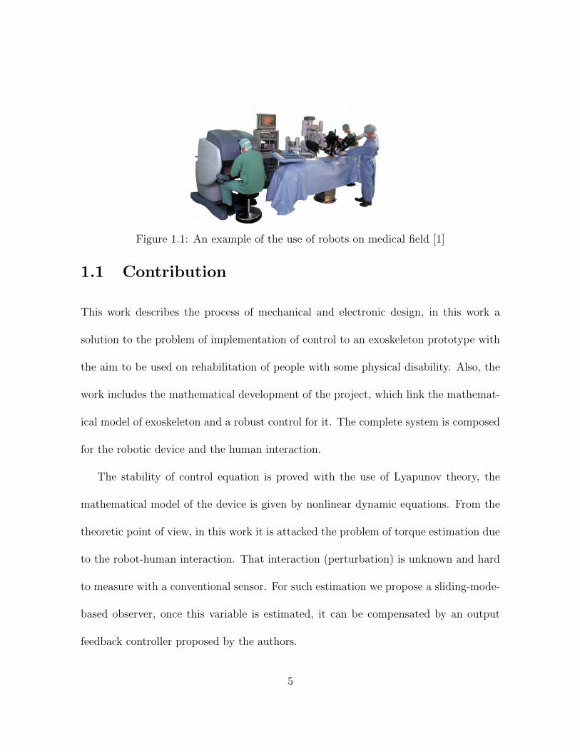
Figure 1.1: An example of the use of robots on medical field [1]
1.1 Contribution
This work describes the process of mechanical and electronic design, in this work a
solution to the problem of implementation of control to an exoskeleton prototype with
the aim to be used on rehabilitation of people with some physical disability. Also, the
work includes the mathematical development of the project, which link the mathemat-
ical model of exoskeleton and a robust control for it. The complete system is composed
for the robotic device and the human interaction.
The stability of control equation is proved with the use of Lyapunov theory, the
mathematical model of the device is given by nonlinear dynamic equations. From the
theoretic point of view, in this work it is attacked the problem of torque estimation due
to the robot-human interaction. That interaction (perturbation) is unknown and hard
to measure with a conventional sensor. For such estimation we propose a sliding-mode-
based observer, once this variable is estimated, it can be compensated by an output
feedback controller proposed by the authors.
5

In the next section we talk about causes of disability to give the reader a better
context and to get familiar with terms that will be handled throughout this work.
1.2 Introduction
Nearly 70 percent of patients with SCIs (Spinal Cord Injuries) have reported reduced
quality of life, significant levels of pain, and a reduction in long-term satisfaction level
[3]. Also strokes are the second largest cause of disability worldwide after dementia [5].
Figure 1.2: Principal causes of spinal cord injuries. [4]
It is caused by an interruption of blood flow to the brain. It results in brain cell damage
and could be fatal. A stroke typically manifests itself with the sudden onset of local
neurological deficits, such as partial loss of movement, sensory deficit, or difficulties
with speech. Stroke are classified by their cause in two main types: ischemic and
hemorrhagic (see fig.1.3).
• In the ischemic stroke, which occurs in approximately 85−90 percent of strokes, a
6

blood vessel becomes occluded and the blood supply to part of the brain is totally
or partially blocked.
• The hemorrhagic stroke, or intracranial hemorrhage, occurs in about 10 − 15
percent of strokes, when a blood vessel in the brain bursts, spilling blood into the
spaces surrounding the brain cells. Hemorrhagic strokes generally carry a greater
risk of death and permanent disability than ischemic strokes [6].
Figure 1.3: Both types of stroke and how they are produced [7].
The neurological impairment after stroke frequently leads to hemiparesis or partial
paralysis of one side of the body that affects the patients ability to perform Activities of
Daily Life (ADL) such as walking and eating. Physical therapy, involving rehabilitation,
helps improve the lost functions as movement of arms or legs.
Specific parameters must be made sequentially to an effective exercise program
during the therapy. These to ensure that patients can be able to back to normal
activities. Each of these parameters must be restored to at least pre-injury levels time.
7
In their proper order these parameters are [8]:
• Flexibility and range of motion
• Strength and muscle endurance
• Proprioception, coordination and agility.
Each one of above points has as objective recover motor plasticity of the patient and
therefore improve motor recovery (in this case as is mentioned on [9], range of motion
of elbow is approximately 0 to 110) and minimize functional deficits. Rehabilitation
process depend on limb that need it. Rehabilitation is the main treatment to these
disabilities, a process which allows the stroke patient to relearn the best possible use of
their limbs and recover independence [10].
It is necessary to define planes that cross the body to make easiest the comprehension
of limbs movements, these are:
• The sagittal plane: is the dominant plane of motion during human locomotion.
Joint motion in this plane is simply referred to as flexion (positive direction).
• The coronal plane: Motion of the hip; in this plane it is referred to as abduction
(away from the center of the body) and adduction. Further, motion of the ankle
is referred to as eversion (away from the center of the body) and inversion.
The remaining Degrees of Freedom (DOF) of the hip and ankle are simply referred to
as rotation (see fig.1.4) [11].
8

Figure 1.4: Planes of human body [12].
Other causes as overhead work as in assembly line is a risk factor of musculoskeletal
injury as show [13]. Also as is mentioned in [14] a lot of tasks that require to maintain a
static posture on arm, while the person exerts force in hand of the same arm is another
cause of injuries. Despite of evolution of technology a lot of processes still require the
presence of a human operator to perform certain tasks due to decision making and
cognitive reasoning [15]. In case of industry application, the use of exoskeletons is
relatively new and advances made in these devices and their application are few, the
advances made in laboratory tests are greater [16]. Also workers will prefer not to use
the devices if the loads are within their capacity of resistance, if the device hinders
their movements or if these require a long apprehension, it has also been said that
the devices are very expensive [17]. In industries such as naval or aerospace they use
exoskeletons to reduce the risk of injury to the upper limbs, however it is not mentioned
if these exoskeletons transfer these risks to other areas of the body [18]. Ergonomic
9

off-body materials handling devices, such as: hoists, lifts, and body slings are being
used to reduce workers mechanical exposure to these acute and cumulative Risk Factors
(RFs), while still maintaining a lean production strategy. However, these devices possess
limitations including: large spinal forces due to the inertia of the device and load when
moved dynamically. Using such devices can be time and space consuming. It is very
important to consider the biomechanical load in the joints that were not taken into
account when performing the mechanical design.
This paper provides a possible solution to the factors not considered in the mechan-
ical design of exoskeletons, a robust control that has a disturbance observer that serves
as an estimator of human-machine interaction and thanks to which we can compensate
for this interaction .
The following chapter describes the state of the art of a variety of exoskeletons
for rehabilitation and also the techniques used to generate movement in these devices.
Control strategies and actuators that are implemented in them are also mentioned.
Likewise, the subject of state observers is briefly addressed and how they have been
incorporated into various devices, mainly to estimate disturbances.
10

Chapter 2
State of the art
An exoskeleton is a wearable powered device, typically endowed with an anthropomor-
phic shape. They are usually designed to track user’s motion, and interact with the
user through position, velocity or even force among human and exoskeleton. One of
the areas in which exoskeletons are popular is in the physiotherapy, because it result
in a good option comparing to manual therapy, this is due exoskeletons have a major
duration and potential comparing to fatigue of therapist [19]. Exoskeleton designs can
be classified in terms of their assisted capabilities as either passive or active devices as
mentioned below and that will be widely explained on following subsections.
• Passive exoskeletons are systems that focus on gravity compensation, spring or
even elastic members to store and release energy during movements, for instance
please refer to fig.2.1. The main purpose of passive exoskeletons is providing
11
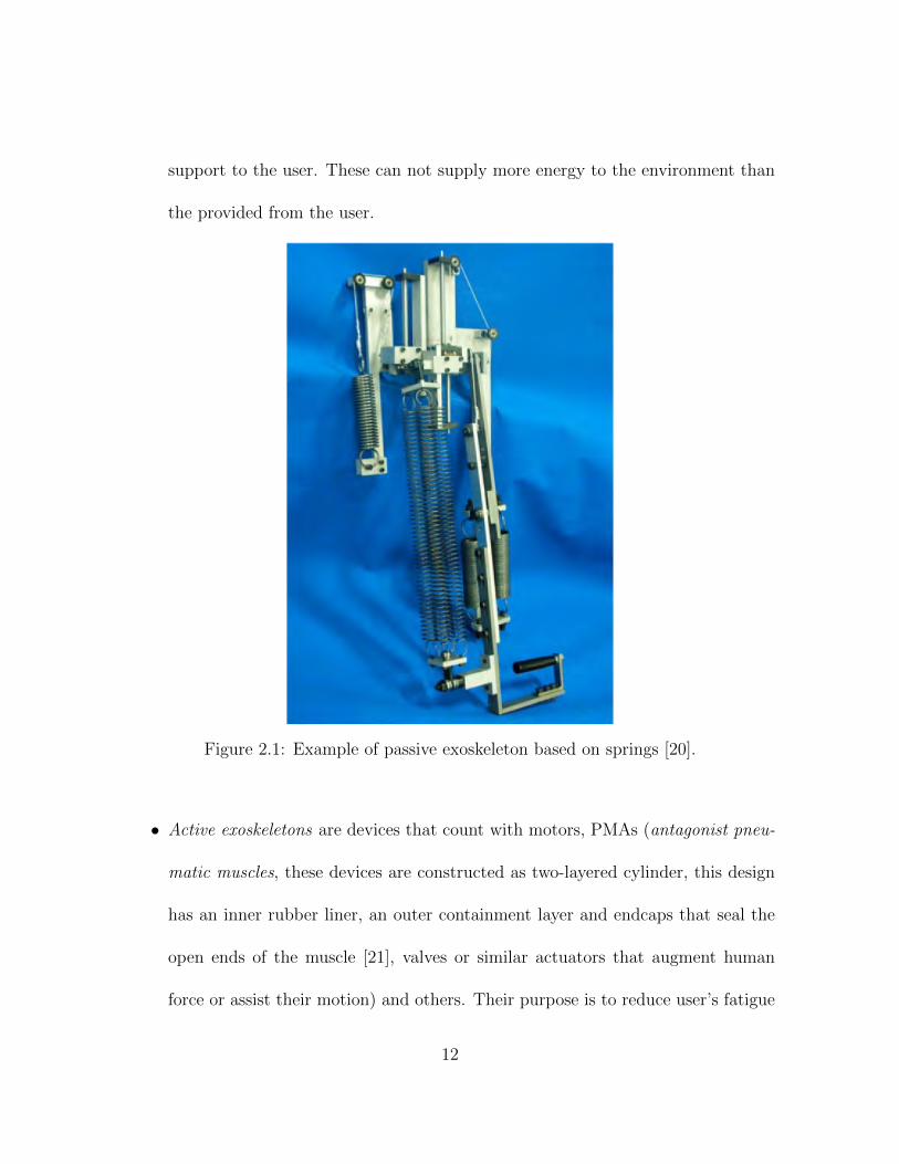
support to the user. These can not supply more energy to the environment than
the provided from the user.
Figure 2.1: Example of passive exoskeleton based on springs [20].
• Active exoskeletons are devices that count with motors, PMAs (antagonist pneu-
matic muscles, these devices are constructed as two-layered cylinder, this design
has an inner rubber liner, an outer containment layer and endcaps that seal the
open ends of the muscle [21], valves or similar actuators that augment human
force or assist their motion) and others. Their purpose is to reduce user’s fatigue
12

and physical stress.
As an important fact, actual hybrid exoskeletons are no commercially available and
they are not expected to be cheap. [22].
2.1 Passive exoskeletons
Some examples of passive-based exoskeleton include [3]
• Passive gravity support. In many instances they provide partial support to the
users by providing strength by means of a mechanical path that direct forces to
the ground.
• Load-carrying assist. A special case of gravity support device. An example of
this kind is the BLEEX system (see fig. 2.2) developed at UC Berkeley [23], in
which the exoskeleton partially or totally supports a load carried by the user, for
example a heavy backpack.
• Force-offsetting assist. As a complement to load carrying capabilities, the system
is developed by James Walsh. It uses passive devices like springs to store energy
released during negative-work phases of the gait cycle. It releases energy during
the positive-work phases to assist the process of walking motion [24].
• Resonance-based assist. This exoskeleton modifies the limb dynamics to make
13

it functioning closer to its resonant frequency, thus helping the user to perform
effectively their own muscles.
Figure 2.2: BLEEX exoskeleton [25].
2.2 Active exoskeletons
Active exoskeletons use different kind of actuators, such as PAM, see fig.2.3 for an
example of this device. Also, active exoskeletons use several kind of sensors, one of
them is the electromyography sensor aka EMG [9]. in the case of control system some
active exoskeletons are based on position and force control [26] but usually the force
14

provided by the user is not measured. This is due to the difficulty in estimating such a
force and the lack of efficient force sensors.
Figure 2.3: PAM system example [27].
2.3 Exoskeleton control
Exoskeletons are used normally for two basic purposes: force augmentation and user
movement control. For instance, the exoskeleton HEXAR (depicted at fig.2.4) is used to
augment the user upper limb force [28]. The interaction between exoskeleton and oper-
ator demands several algorithms, especially of control and estimation [9]. Exoskeleton
like the light exoskeleton (L-EXO) shown at fig.2.5 implements a tracking control based
on sliding mode technique [29]. In [30] an exoskeleton for upper limb with 7 degrees
of freedom (DOF) and a weight of 72.4kg is presented. It has a controller responsible
to track torque commands.
15

Figure 2.4: Hexar system [28]
Figure 2.5: L-exo and human body movements.
16

There are several works of exoskeleton control and estimation presented in the liter-
ature. Researchers have been incorporating more DOF into exoskeletons, to get variety
of upper limb movements. Current upper limb exoskeletons focus on movements of the
shoulder, elbow and/or wrist complex. Several researchers have developed exoskeletons
which include movements of the 2 DOF sternoclavicular joint at the shoulder complex.
For example the tree showed on fig.2.6 [31].
Figure 2.6: Examples of exoskeletons with various DOF, the first one is CADEN-7 [32],second RUPERT IV [33] and the last ARMin III [34]
Also most of the current rehabilitation devices are useful just on some stages of
rehabilitation, especially in cases where no force is received from the patient. For cases
where small forces from patient are presented, exoskeletons with force feedback from
the patient is needed. As the vast majority of these exoskeletons do not estimate the
force exerted by the patient, there is no feedback for the human-robot interaction. Pa-
tient interaction is important since this patient is responsible for giving feedback force
to the device [35, 36]. Also as it is mentioned on [5] the majority of current hybrid
exoskeletons are focused on functional movement rather than on patient monitoring.
17

Most exoskeletons are not available to be portables due actuators that drive function-
ality of these requires to be powerful and it implicates to be weighted and big, also
these kind of exoskeleton are available to be used on rehabilitation only if the patient
count with a bit of force (due to weight), it means that are not optimal to patient that
can not apply any quantity of force. [37]. Hence it is required an exoskeleton capable
to move the limb of the patient when he or she can not apply any strength. Also, it is
desired that the exoskeleton applies a defined movement to the patient in order to act
as a muscle re-trainer.
As far as measurements are concerned, some methods to measure angular position
on exoskeletons of upper limb are:
• Collocate marks on joint and take images of that with CCD cameras and after
use an algorithm to process that and analyze angular parameters
• Using magnetic sensor with 3 axis coupling to joint, it computes 3D orientation
and compare it to earth magnetic axes.
• using Inertial sensor like accelerometers or gyroscopes.
• Using a rotational potentiometer to measure angular position due it haves a linear
dependence to electrical resistance and it provides an angular absolute position.
as is mentioned on [38].
18

2.4 Observers
Human robot interaction is a very difficult an important factor to considerate on system
as exoskeletons due as it is working with 2 systems (human arm and exoskeleton) and
the interaction between these produces vibrations. So, to measure that, exist various
methods:
• Use an artificial impedance to decouple haptic control and model of the virtual
environment.
• model the system and adaptive adjust the controller parameters using sensors
related to the human movement in order to avoid the vibrations.
• considered as a variable forcetorque perturbations in complex 3D workspace. [29]
• create an observer to estimate vibrations caused by this interaction.
[39] In other cases as on developed system on [40] is necessary to obtain a detailed
model of exoskeleton and upper limb to reduce that vibrations produced by interaction
but it result very difficult, however in the same paper is showed the analysis of feedback
linearization that does not requires detail of biological model, but it does not show a
good performance.
Although dynamics of exoskeleton is known, dynamics of human limb generally is
unknown and it change between every single persons. In consequence use of exoskeleton
19

and interaction with human user vary and depends of capacity of adaptation of control
designed [2]. A control strategy that can be helpful are observers.
Observers are an important part of control systems cause these are a tool that
provide information about parameters that, for difficulty, lack of instruments or non
adequate sensors, is not possible to estimate value. In consequence some states of the
system are unknown. These observer are subsystems that emulates original system and
their behavior is related to these. These are designed using information of output of
system and estates that is possible measure. Whit this information is possible say that
observer can be use to estimate human-robot interaction.
2.5 Aim of work
As described in the previous sections, exoskeletons have difficulties to be implemented
due, in part, to the human-robot coupling problem, because it generates unwanted
vibrations and there is no mathematical model to describe it, besides being a device
that, in this case, will be aimed at medical use, it should be very careful and controlled
in relation to the movements made by the device to ensure the safety of the user. The
objective of this work is design and create a prototype (based on its mathematical
model). It has a control system that can follow a certain trajectory (a tracking control)
based on parameters such as the position and speed of the device as well as an estimator
of the human-robot disturbance as it has been investigated in [9, 29, 41, 42] and [28] (a
20

disturbance observer) that will serve to the same control. For the development of the
observer the method of sliding modes was used to generate a compensation, which is
integrated into the control equation to make it robust.
21

Chapter 3
System description and problem
statement
To an adequate rehabilitation exoskeleton design, it is necessary to consider a mathe-
matical model that represents the human-robot interaction due to the coupling of two
systems (human and robotic) [26, 28,42]. However, in the vast majority of works, only
the modeling of the robot itself is considered, lacking of any function that models the
aforementioned interaction [41].
3.1 State of the art of exoskeleton modeling systems
Various devices has been development and these have different ways to act and be mod-
eled. Here are exposed some modeled systems of exoskeletons that exist on literature,
22

for example the device developed by Jozef Stefan Institute [9]. It was modeled based
on model of force of muscle:
Fm = ( f0 f1 fvα + Fp) cos(φ)
where f0 represent the optimal muscle force; f1 is the active force-length relationship;
fv is the force-velocity relationship; φ is the muscle tendon penation angle; and α is the
activation level.
Other devices presented at [41], [29], [42], [40] and [28] (among others) use models
based on robot equation due to the number of DOF that they have. The base model
equation of such exoskeleton is as follows
M(q) Üq + C(q, Ûq) Ûq + G(q) = u (3.1)
where every variable correspond to one parameter of the device, q denotes position; Ûq
is the velocity; Üq is the acceleration; M(q) inertial matrix; C(q, Ûq) is the centrifugal and
Coriolis matrix; and G(q) is the gravity torque. This modeling is the most popular one,
however in general it lacks of any term that relates the human-robot interaction.
As human-robot interaction represents a challenge since it causes vibrations [30],
various methods has been applied as an alternative such as artificial impedance or
using the energy transferred in the system with concepts such as time domain passivity.
23

However, both have problems, cause the first one reduces the performance and the other
one has problems with the computational burden [39]. Now like a better alternative for
that, a term of disturbance (δ) that represents that interaction was proposed.
3.2 Mathematical model
It was necessary to obtain a simple mathematical representation of system that will
be easy to control but also describe system on a optimal way. This means represent
principal parameters on a generalization but without a big loss of information. The
mathematical model of exoskeleton was developed based on Lagrangian approach and
the obtained model is similar to an actuated pendulum [43] (the joint of elbow) plus
an unknown term that models the human-robot interaction, (a representation on free
body diagram for the exoskeleton is shown at Fig. 3.1. It exposes the relationship
between fixed frame and actuator frame and how coordinate system changes between
each frame).
Lagrangian equation is given as:
L = K − υ (3.2)
where L is the Lagrangian, K kinetic energy and υ is the potential energy. By using
24

0z
0x
0y
1y
1x
1z
Figure 3.1: System diagram, that show relation between fixed frame and first frame(the one of actuator) based on Denavit-Hartenberg convention.
the Lagrangian approach and using (3.2) is obtained:
ξi =ddt∂L∂ Ûλi− ∂L∂λi
(3.3)
The equations of K is:
K =1
2Ûθ2l (3.4)
where Ûθ and l represents angular velocity and length of system respectively. Also the
equations of υ is:
υ = lmg(1 − cos (θ)) (3.5)
Where m is the mass and g is the gravity of the piece respectively and θ is the angular
25

position of joint. Then replacing equations (3.4) and (3.5) in (3.2):
L =1
2Ûθ2l − lmg(1 − cos (θ))
and using the new Lagrange equation on equation (3.3):
∂L∂ Ûθ= Ûθl → d
dt∂L∂ Ûθ= Üθl and
∂L∂θ= −lmg sin (θ)
in this case Üθ is angular acceleration of joint. Considering that ξ is given by torque
and friction (ξ = T − F Ûθ) [43] and also a perturbation δ, originated by human-robot
interaction:
Üθl + lmg sin (θ) = T − F Ûθ + δ
finally we get (in state space)
Σ =
Ûθ1 = θ2
Ûθ2 =T − Fθ2 − lmg sin (θ1) + δ
l
that represents control term of the system. Mathematical model defined in this section
represents the physic behavior of system, based on cinematic and kinematic energy. It
is a starting point to continue with analysis. Then is necessary to delimit problem or
problems to solve based on this model.
26

3.3 Problem statement
Considering the previously modeled system it is possible to see that, before all, due
to the human-robot interaction it is produced a term (δ, that was defined previously
and will be consider it time dependent and derivable) that can not be measured but
it affects the system’s behavior, so it is necessary to find a way to estimate that value
(introduce an observer) of that term. In that way we will have an approximation of the
value [39] with the sake of avoid a strange behavior of system. The problem is twofold:
first, from a simple robot model it is necessary to introduce a function that models the
interaction between the machine and human. For that aim we design a sliding-mode-
based observer for the estimation of such unknown function. Second, once this function
is known, a controller is designed with the aim of compensating the robot-machine
interaction. This is possible defining it as follows:
Problem 1. Designing a system (observer) (δ) that is able to estimate an approxima-
tion of value of the term δ i.e. converges to it in a finite time with a little error.
In consideration of the necessity of strength feedback is necessary to apply a control
system based on it and, because of the trajectories already set, we can focus on velocity
of the device doing that the strength reference modifies the velocity. This because
EMG signal is directly related with muscle length and velocity of contraction of it
and also EMG signal has a direct relation to muscle force [44], so is possible to say
that velocity of movement modifies force applied on muscle of patient. In this way is
27
available estimate it and, indirectly, control muscle force of patient in an non-invasive
way. As a consequence, an adaption of the system to reach the required force level could
be achieved. So it requires a velocity control for all the system that cushion the effect
of δ, this due to force of the patient will be controlled through velocity of actuator and
it is needed that this velocity will be guided by a reference in such a way that it will
be safe for the patient.
Problem 2. Using the previous designed perturbation observer, design a velocity control
for mathematical model described on system Σ, such that it can be able to follow a
velocity reference given by a time variant function, i.e. a tracking control.
The objective of this work is to find a precise solution to both problems, using
nonlinear control methods.
28
Chapter 4
Main result
4.1 Introduction
Taking into account the previous information of the theoretical framework, the problem
statement and the objective that is expected to be achieved in this work, it is possible
now to begin developing the solution, which starts from the mathematical model of
the device and is based on its position and velocity. It is also introduced the observer
of disturbances, which had been previously mentioned, as a way to complement the
control. In this section the theorems of observer and control are presented, developed
and tested using the Lyapunov technique.
A control diagram of this control system is shown at Fig.4.1.
29

Force Of patient
EMGSignal
SystemVelocity
SystemPosition
Tracking Control
PerturbanceObserver
𝐹
𝐹𝑐 𝐸𝑀𝐺𝑐
𝐸𝑀𝐺
𝑉 𝑉𝑐
𝑃 𝑃𝑐
𝑥, 𝑥
𝛿
𝑉
Figure 4.1: Here is presented a simple diagram of control system where c means ”cor-rection” as an indication of change, as is possible see observer is a primordial stepto control the entire system because it provides all the first correction and the otherchanges in consequence of that.
For simplicity parameters are adjusted as follow:
l = 1
F = a
mg = b
and
T = u
It is necessary show some examples of observers, beginning for one used on linear
systems, the Luenberger observer. Below is a system to which an observer will be
30
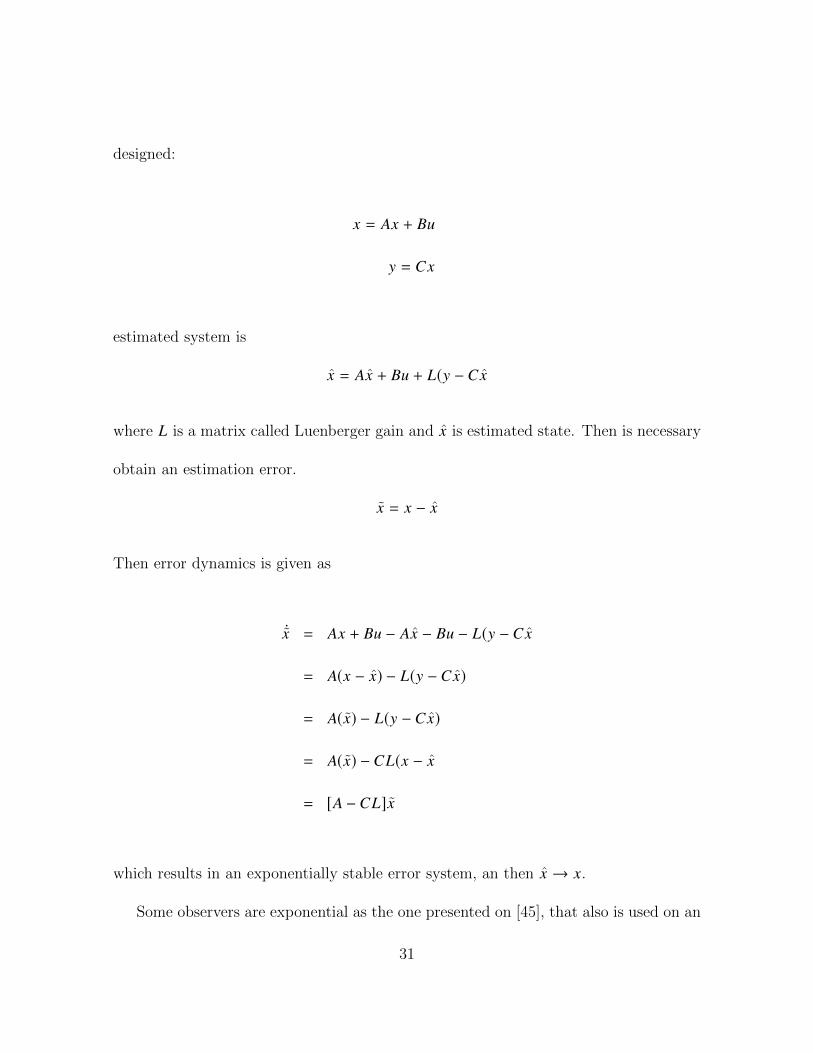
designed:
x = Ax + Bu
y = Cx
estimated system is
x = Ax + Bu + L(y − Cx
where L is a matrix called Luenberger gain and x is estimated state. Then is necessary
obtain an estimation error.
x = x − x
Then error dynamics is given as
Ûx = Ax + Bu − Ax − Bu − L(y − Cx
= A(x − x) − L(y − Cx)
= A(x) − L(y − Cx)
= A(x) − CL(x − x
= [A − CL]x
which results in an exponentially stable error system, an then x → x.
Some observers are exponential as the one presented on [45], that also is used on an
31

exoskeleton. Other observers (of disturbance and used for spacecraft formation flying)
is as the one that can appreciate on [46] and the one of [47]. The observer mentioned
on [48] is used to estimate mechanical values that will be used on a control to track the
wind turbine maximum power point. Observer development on [49] is used to estimate
the angular velocity of a rigid body from vector measurements. It should be noted that
the aforementioned observers are non-linear.
4.2 Main Result
As is mentioned on [40] better results of control for upper limb are obtained using sliding
mode. In this section we present our main result: an observer for an unknown distur-
bance. Such disturbance represents the force interaction between human and machine.
The observer is based on the sliding mode approach. Once the observer is designed,
the estimated state is used for feedback in a controller, as a result a feedback controller
is obtained. Let’s begin with a simple scalar system which shows our methodology.
Example 3. Scalar system. Let the system
Ûx = −ax + δ(t)
y = x
where x is the system state; y is the available output; and δ(t) is an unknown distur-
32

bance. Define the disturbance estimation error and estimation state error as follows
δ = δ − δ (4.1)
x = x − x (4.2)
Consider the following estimator
Ûx = −a1 x + δ − θ(x − x) (4.3)
Ûδ = −k1 sign(x − x) − k2δ. (4.4)
where θ ∈ R+. Then the error dynamics of (4.1) together with (4.3) is given as
Ûx = −(a1 + θ)x + δ
Ûδ = −k1 sign(x) − k2δ − k2δ − Ûδ
Proof.
V = a1 |x1 | + b|x2 | +1
2δ2
33

deriving, we have:
ÛV = a sign (x1) Ûx1 + b sign (x2) Ûx2 + δ Ûδ
= a sign (x1)x2 + b sign (x2)(u1 − ax2 + x′ − a f2(t) + δ − Ûf2(t)) +
δ Ûδ
= a1 sign (x1)x2 + b sign (x2)(u1 − ax2 + x′ − a f2(t) + δ − Ûf2(t)) +
δ(−k1 sign (e) − k2 sign (δ) − f (t))
So making the control
u1 = a1x2 − x′ + a f2(t) − ( Ûf2(t) + K x2)l
34

ÛV = −kb|x2 | + sign (x1)(a1x2 − k1δ) + sign (x2)(bδ) −
k2 sign (δ)δ f (t)δ
≤ −kb|x2 | + sign (x1)(a1x2 − k1δ) + sign (x2)(bδ) −
k2(sign (δ) + sign ( f (t)) + 1)δ − f (t)δ
≤ −kb|x2 | + sign (x1)(a1x2 − k1δ) + sign (x2)(bδ) −
k2δ − k2δ sign ( f (t)) − k2δ − f (t)δ
≤ −kb|x2 | + (a1x2 − k1δ) + bδ − k2δ + k2
δ −k2δ − f (t)δ
consider:
| f (t)| < D
k2 = D
have:
ÛV ≤ −kb|x2 | + (a1x2 − k1δ) +bδl− k2δ + Dδ
≤ −kb|x2 | + (a1x2 − k1δ) + bδ
35

also consider:
k > b > 0
k1 = b
finally:
ÛV ≤ −kb|x2 | + a1x2
so now we define the next statement:
b > a1
this helps the observer to be negative definite.
The main results is stated in the following theorems.
Theorem 4. To estimate perturbations of the system described by Σ it can be designed
an observer based on sliding modes and error between output and observer of it. The
next equation is a control for the observer to estimate human-robot interaction.
u = ax2 − x′ + a f2(t) − ( f3(t) + K x2)
Ûδ = Ûδ − f (t)
36

where
Ûδ = −k1 sign (x1) + k2 sign (δ)
δ = δ − δ
Proof. assumption:
• control u is global Lipschitz respect to vector of states ®x =
x1
x2
• there is a set of controls u ∈ L∞(R+,R2), such that any trajectory x(t) associated
with any u ∈ u is bounded.
Equations of model need to be modified to be able to follow references of velocity and
movements i.e. a tracking control system. So system must be reconditioned as follows:
Σ =
Ûx1 = x2
Ûx2 = u − ax2 + x′ − a f2(t) + δ − f3(t)
where
x2 = Ûθ1 − Ûθ1d
x′ = −b sin (x1) cos ( f1(t)) − b sin ( f1(t)) cos (x1)
And f3(t) is an assumption of perturbation is bounded by a function as is mentioned
37

on [50]. Due to is needed to know velocity of device and estimation of position to
determine perturbation (x1 − x1), it is necessary to include an observant system, based
on [51]. So the system Σ is modified:
Σ =
Ûx1 = x2
Ûx2 = u − ax2 + x′ − a f2(t) + δ(t) − S−1α C′[x1 − x1]
That is the original system with a corrective term where:
x′ = −b sin (x1) cos ( f1(t)) − b sin ( f1(t)) cos (x1)
where C = [1, 0], Sα is solution of:
αSα + AT Sα + SαA − CTC = 0 (4.5)
where:
A =
0 1
0 0
and the solution of (4.5) is given by:
sα(i, j) =(−1)i+ jC j−1
i+ j−2
αi+ j−1
38

for 1 ≤ i and j ≤ 2 where:
Cqp =
p!
(p − q)!q!
is an exponential observer for Σ such that converges in a finite time.
Theorem 5. The next equations describe a velocity control for the system Σ, where U
is a control entrance that makes the system globally asymptotically stable.
u = Fx2 − x′ + F f2(t) − δ − ( f3(t) + k(x2))l (4.6)
and
Ûδ = −k1 sign (x1) − k2 sign (δ) (4.7)
where:
f2(t) = Ûf1(t)
where f1(t) is the reference of desired velocity that vary on time and is continuously
differentiable
Proof. Is necessary to propose a Lyapunov candidate function such that, according to
the stability theorems of non autonomous systems, W1(x) and W2(x) should be K or
K∞ (∀t ≥ 0 and ∀x ∈ Rn, where W1(x) and W2(x) are continuous definite functions on
Rn [50]) and according to La Salle generalization [50], W3 should be a positive definite
39

and radially unbounded function.
W1(x) ≤ V(t) ≤ W2(x) (4.8)
ÛV(t, x) = ∂V∂t+∂V∂x
f (x, t) ≤ −W3(x) (4.9)
Taking these on consideration it can be propose a Lyapunov function:
V = a1 |x1 | + b1 |x2 | +1
2δ2 (4.10)
The derivative of this is computed as:
ÛV = a1 sign (x1) Ûx1 + b1 sign (x2) Ûx2 + δ Ûδ
= a1 sign (x1)x2 + b1 sign (x2)(u − ax2 + x′ − a f2(t)
+δ − Ûf2(t)) + δ Ûδ
= a1 sign (x1)x2 + b1 sign (x2)(u − ax2 + x′ − a f2(t)
+δ − Ûf2(t)) + δ(−k1 sign (e) + k2 sign (δ) − f (t))
So making the control
u = ax2 − x′ + a f2(t) + Ûf2(t) − k x2
40

We have:
ÛV = −kb1 |x2 | + a1 sign (x1)x2 + δ(−k1 sign (e) + k2 sign (δ) + f (t))
As we can see state x1 is bounded by the sign () function so taking in to account that:
sign (a + b) ≤ sign (a) + sign (b) + 1
we have:
ÛV ≤ −kb1 |x2 | + a1 sign (x1)x2 + δ(−k1 sign (e) +
k2 sign (δ) + k2 sign (δ) + k2 + f (t))
≤ −kb1 |x2 | + a1 |x2 | + k1δ + k2
δ + k2δ + k2
δ +f (t)
δconsidering:
| f (t)| < D
|k2 | > D
41

have:
ÛV ≤ −kb1 |x2 | + a1 |x2 | + (k1 + 3k2)δ + D
δ (4.11)
also consider:
k > b1 > a1
|k2 | > |k1 |
k2 < 0
And considering f (t) like a function that is bounded above and below it’s possible to
say that (4.11) is a defined negative function:
ÛV ≤ −k |x2 | + k2δ
Also is easy to see that a positive definite function exists and satisfies inequality (4.9).
This function is given by:
W3(x) = a1x21 + b1x22 + δ2
that is a globally radially unbounded function, and also exist functions that satisfy
inequality (4.8):
W1(x) = |x |1 + |x |2 +1
4δ2
42

and
W2(x) = 2a1x21 + 2b1x22 + δ2
and in both cases are K∞ functions so we can say that our function (4.10) is bounded
above and below and fulfill inequalities (4.8) and (4.9) therefore (by LaSalle general-
ization) it is globally asymptotically stable.
And finally, next equation serves to prove finite convergence time of perturbation
observer, based on equation ÛV = −Ka.
t =−v(1−a)
0
K(a − 1) (4.12)
where K and a are constants and 0 < a < 1. So first, solving equation:
ÛV = −KVa
dvVa = −kdt∫ V
V0
1
Va · dV =
∫ t
0K · dt
V (1−a)
1 − a−
V (1−a)0
1 − a= −Kt
V (1−a)
1 − a= −Kt +
V (1−a)0
1 − a
V (1−a) = Kt(a − 1) + V (1−a)0
V =1−a√
Kt(a − 1) + V (1−a)0
43

taking last equation we can use it to find convergence time like follow:
0 =1−a√
Kt(a − 1) + V (1−a)0
0 = Kt(a − 1) + V (1−a)0
−V (1−a)0
K(a − 1) = t (4.13)
As it can be seen on equation (4.13), convergence time is defined by the initial condition
V0, constants K and a value. It proves that observer converges on finite time.
44
Chapter 5
Numerical and experimental results
Simulations of control system and behavior and respective results are show below with
a little explanation of graphs an a brief description of parameters and values taking
in to account to every one. Simulations of closed-loop system with the control and
observer were conducted using Matlab Simulink, this helped to visualize behavior and
effectiveness of control system. Normalized values for model parameters were consid-
ered; a signal θd = sin(t) was chosen to follow; α = 2000 and a constant D = 3 (that
represent the bounded of |δ |) as parameters to work it and show effectiveness, that
parameter was selected randomly, the function sin (t) emulates a repetitive movement
on sagittal plane, it is a constant flexion and extension of muscle of arm, as it would
be done in therapy, to return the plasticity to this (see fig.5.1).
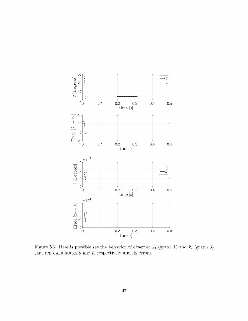
The graphics of the convergence of the observer of system and controller are depicted
45

Figure 5.1: description of movements of arm to therapy rehabilitation [52]
at 5.2 (where is show how observer of states converges to original states), 5.3 and
5.4 (in every picture is possible appreciate the functionality of tracking control that
converges to the function to follow (sin(t)) and results of perturbation estimation on
5.5 (that shows the difference (error) between δ signal and δ). In every results it can be
appreciate that system converges in finite time (on question of seconds) so the system
is available to work.
In the case of observant, it was try to determine human-robot interaction (vibrations
caused by these) and it was represented by a generated random signal and on simulation
was defined by pseudo code show on algorithm 1 that provides a non periodic behavior.
Finally, discussion of these results and conclusions are presented on final chapter
were analyze that and criticize it.
46
time [s]0 0.1 0.2 0.3 0.4 0.5
3[D
egre
es]
0
10
20
303
3
time[s]0 0.1 0.2 0.3 0.4 0.5
Err
or[x
1!
x1]
-20
0
20
40
time [s]0 0.1 0.2 0.3 0.4 0.5
3[D
egre
es]
#104
-2
-1
0
1!!
time[s]0 0.1 0.2 0.3 0.4 0.5
Err
or[x
2!
x2] #104
-2
-1
0
1
Figure 5.2: Here is possible see the behavior of observer x1 (graph 1) and x2 (graph 3)that represent states θ and ω respectively and its errors.
47

time [s]0 2 4 6 8 10
3[D
egre
es]
-5
0
53
3d
time[s]0 2 4 6 8 10
Err
or[x
1d!
x1]
-5
0
5
Figure 5.3: Above on first graph is possible appreciate the behavior of states x1 thatrepresent position of system and how is that it converges to x1d that represent thefunction to follow, and the second one shows error between both and how it convergesto zero.
time [s]0 2 4 6 8 10
![r
ad=s
]
-5
0
5!!d
time[s]0 2 4 6 8 10
Err
or[x
2d!
x2]
-5
0
5
Figure 5.4: First graph shows second state x2 behavior and the function to follow x2dand also, on second, the error between both, with a window of 10 seconds (this time isjust to be able to appreciate the convergence on finite time of system)
48

time [s]0 10 20 30 40 50 60 70
Per
turb
atio
n
-5
0
5/
/
time[s]0 10 20 30 40 50 60 70
Err
or[/!/]
-5
0
5
Figure 5.5: On first graph is easy to see that observer δ (dashed line), using a slidingmode, converges quickly to original state δ and, second graph, shows the error betweenobserver and original state. (the time windows of 70 seconds is just to show that errorkeep going be little on a big time.)
Algorithm 1 Perturbation algorithm
if t < 10 thenδ← 0.5 sin (t)
else if 10 ≤ t and t < 30 thenδ← 1.5 sin (t)
else if 30 ≤ t and t < 50 thenδ← 0.8
elseδ← sin (t)
end if
49

Chapter 6
Experimental platform and
experiments
Here it is described the mechanical system, how it was designed, parameters and adap-
tations that was taking into account, materials, shape and size. The way to control
electronic components and interaction with mechanical model is also described.
As is possible to see on literature, there is an existent necessity to obtain a device
that collect different characteristics as portability, functionality and effectiveness, in
consequence it tried to design a device that count with all of that. It is necessary
remark that it is a first design and due this it had a lot of modifications. This device
will be used just for tests, but not yet to rehabilitation therapy.
50
6.1 Mechanical design
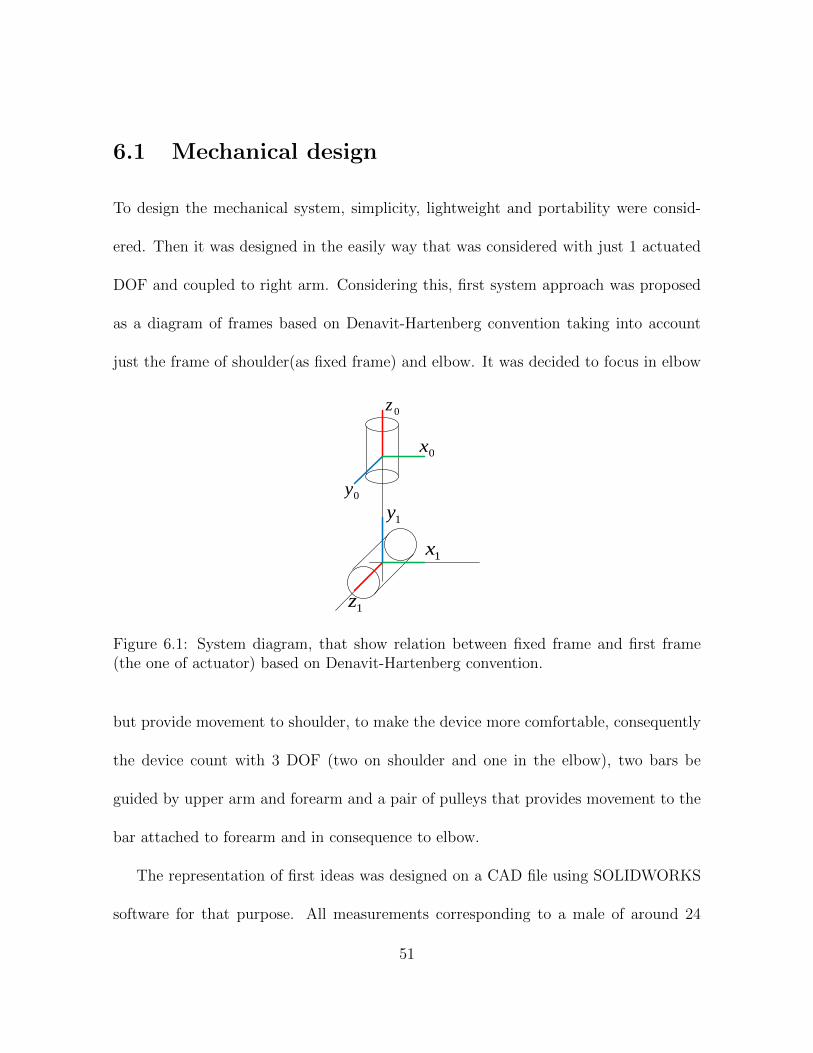
To design the mechanical system, simplicity, lightweight and portability were consid-
ered. Then it was designed in the easily way that was considered with just 1 actuated
DOF and coupled to right arm. Considering this, first system approach was proposed
as a diagram of frames based on Denavit-Hartenberg convention taking into account
just the frame of shoulder(as fixed frame) and elbow. It was decided to focus in elbow
0z
0x
0y
1y
1x
1z
Figure 6.1: System diagram, that show relation between fixed frame and first frame(the one of actuator) based on Denavit-Hartenberg convention.
but provide movement to shoulder, to make the device more comfortable, consequently
the device count with 3 DOF (two on shoulder and one in the elbow), two bars be
guided by upper arm and forearm and a pair of pulleys that provides movement to the
bar attached to forearm and in consequence to elbow.
The representation of first ideas was designed on a CAD file using SOLIDWORKS
software for that purpose. All measurements corresponding to a male of around 24
51

years, also it was taken on count a previous existent designs of an exoskeleton of upper
limb as the one described on [38].
Figure 6.2: Design of titan Arm [53]
Figure 6.3: Mechanical design of exoskeleton for elbow
The back of system consists on a plate of aluminum that will be burden by patient
as a backpack as we can see on Fig. 6.5, also this plate will contain the electronic
system and a pair of pulleys. This plate is just a rectangle adapted to size of the back
of the patient.
52

Figure 6.4: Isometric view of CAD of the exoskeleton.
Figure 6.5: Backpack structure
53

The shoulder joint counts with 2 DOF, with a L shaped structure and 2 holes to
put bearings and give movement to shoulder of patient, also this piece acts as union
between back and arm parts.
Figure 6.6: L shaped piece of shoulder
Arm piece was designed to be similar to a bar but with a circle structure on final of
piece (fig 6.7). It count with 4 holes; 1 to attached to shoulder piece, 2 to attached to
PLA piece that will hold arm and the other one, located on circle part, to be attached
to the pulleys.
Figure 6.7: arm piece
Pulleys are a very important part of the system. due to it, along with DC motor,
they provide movement to elbow joint. 2 pair of pulleys were created; one to be placed
54

on back, directly to motor axis, and the second one to be placed on elbow joint. All
pulleys have canals along of its circumference, of 5 mm of width, and have a little cut
L shaped with dimensions of 26x26 mm. An image of these pieces is shown in Fig. 6.8.
Figure 6.8: Pulleys view
On canals of pulleys there will be placed 2 iron cables (one each to just one pulley
of every pair) to generate tension and, in consequence, move pulleys and elbow. As we
can appreciate in Fig. 6.8, the DOF will move around an axis. One of them will move
it from 90 to 180 degrees and the other one form 90 to 0 degrees.
PLA pieces were designed to be adapted to human arm and printed on 3D printer
(Fig. 6.9). This pieces will hold the arm of patient with help of straps. Forearm piece
55

is very similar to the arm piece. It has the same shape and number of holes. The hole
of the circular part is attached to elbow and the other 3 to piece of forearm.
Figure 6.9: PLA piece for forearm
6.2 Electronic system
The electronic system will be placed on back (into a box) to reduce the load supported
by patient and for proximity to the DC motor. The electronic system is simple (in this
first prototype). It just contains a microcontroller, an encoder, an H bridge, a motor
and a battery as power source. Sensors signals (encoder and EMG signal) will be read
by the microprocessor and processed by it. It will be placed in the box aforementioned
and this and the other components will be powered by the battery. The encoder will
not be placed directly on elbow joint, as the DC motor will be mounted on back and,
56

Figure 6.10: pulleys on elbow place
how system is guided by pulleys and it has a relation 1:1 encoder will be mounted on
axis of motor.
EMG signal needs to be taken directly of muscle to ensure a correctly measurement
of force. To solve that and avoid taking the signal directly this will be read by the
microcontroller using a pad extension that has 3 electrodes and thanks to it, it is not
necessary to place the sensor directly on muscle.
Battery will be located in the box. This battery needs to have a capacity to give
minimally 4A and 12V to ensure a correct functioning of the motor. Also an H bridge is
needed to help the motor to be driven by the microcontroller. The H bridge simulation
and the PCB design was done using Proteus software. It counts with 2 canals and
ensures a capacity to support 4.5 A per canal. A view of the PCB model is shown on
57
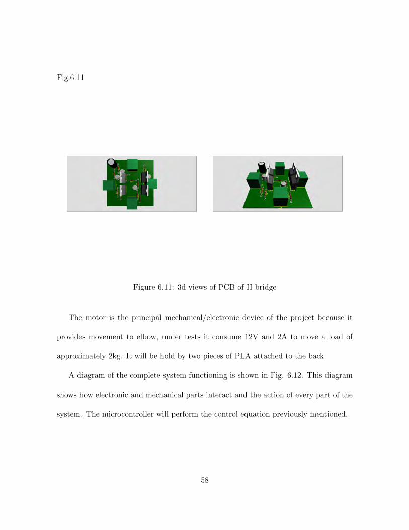
Fig.6.11
Figure 6.11: 3d views of PCB of H bridge
The motor is the principal mechanical/electronic device of the project because it
provides movement to elbow, under tests it consume 12V and 2A to move a load of
approximately 2kg. It will be hold by two pieces of PLA attached to the back.
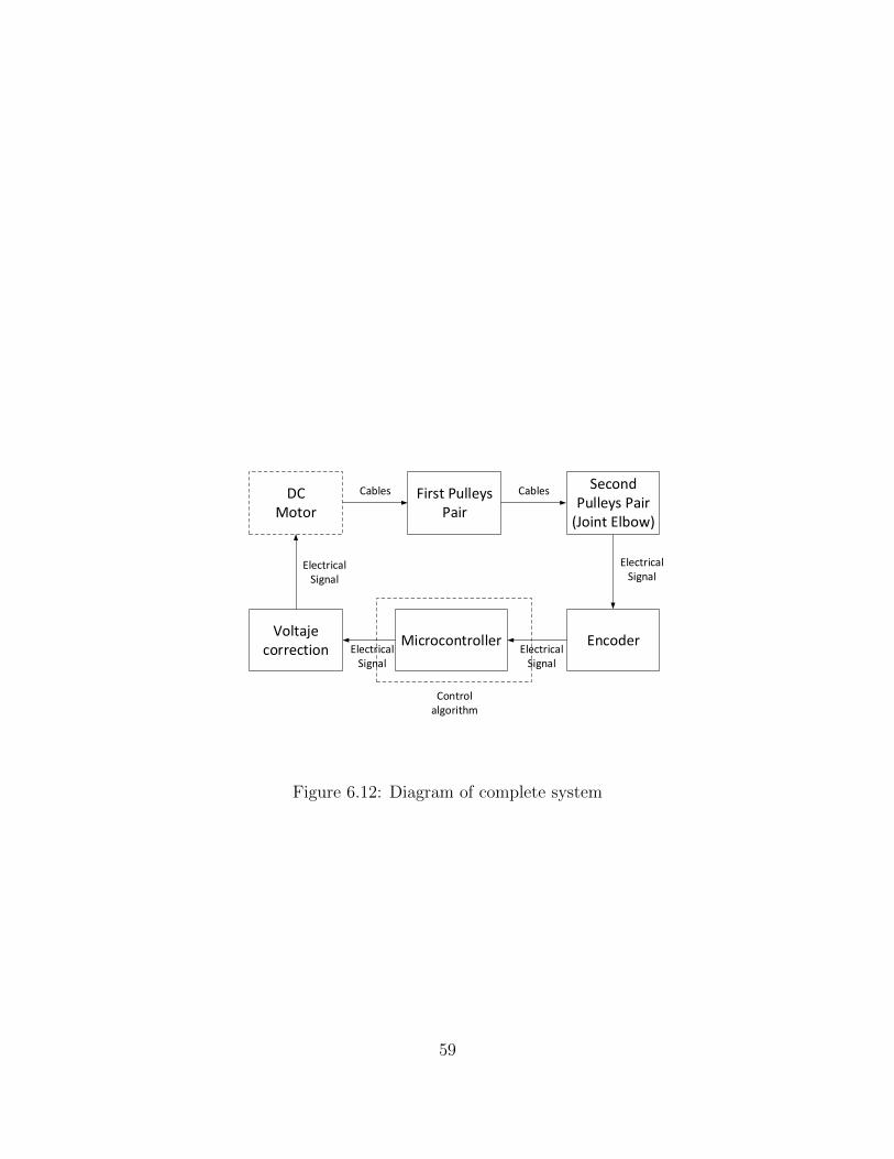
A diagram of the complete system functioning is shown in Fig. 6.12. This diagram
shows how electronic and mechanical parts interact and the action of every part of the
system. The microcontroller will perform the control equation previously mentioned.
58
DCMotor
First PulleysPair
Voltaje correction
Microcontroller
Second Pulleys Pair
(Joint Elbow)
Encoder
Cables
ElectricalSignal
Controlalgorithm
ElectricalSignal
ElectricalSignal
Cables
ElectricalSignal
Figure 6.12: Diagram of complete system
59

6.3 Experiments
The final prototype of the exoskeleton is shown at Figures 6.13 and 6.14. Exoskeleton
was directed tested by applying a sequence of movements using an arduino. Measures
were made with a simple rotative encoder to delimit movements.
Figure 6.13: Isometric view of mechanical prototype with the pulleys, cables and PLApiece
60

Figure 6.14: View of pulley system of back where motor is placed, it counts with anstructure to fixed it and avoid it rotates due tension of cables
6.4 EMG
When the muscle generate force an electrical signal is generated that is associated to
this, this signal can be measured using electrodes and is called EMG (electromyogra-
phy). The EMG is the method of sensing and recording the electrical activity of a
muscle, including information about the physiological processes that occur during mus-
cle contraction [44]. Muscle force refers to the ability of muscle to generate tension and
this depends of the length of muscle and the angular position of this directly related
to that length [44]. Some factors that intervene on force generation are showed on fig
6.15.
As is mentioned on [54], in patients with spasticity after a stroke exist a decoupled
on relation between EMG signal and muscle force. Also relation between EMG signal
and muscle force (during voluntary contraction) is not clear at all. Some authors have
61

concluded that exist a proportional relation for isometric and isotonic contraction with
a constant velocity but others said that this relation is non linear. In most cases non
linear relation increases with increasing force or muscle contraction [44]. Even so EMG
Figure 6.15: Diagram that shows different factor associated to muscle force generation.[44]
signal is good reference to estimate human robot interaction. This signal will be use
to estimate stage of rehabilitation that patient needs and his progress. EMG signal is
used in several hybrid exoskeletons and it showed that is the best method to obtain
information of patient but, at same time, the most complex [5]. Some devices that use
that sensor are Orthojacket, FES/Robot Hand, RUPERT (mentioned on [5]), Robot
Suit HAL-5, CADEN-7 (see [38]) and various other.
Exist a function that describes the relation between distance of motor unit and
recording electrodes. That function is:
V =V0
r/r0D
62

where D and V0 are constant and r0 some reference distance from the electrical center
of the motor unit, where V = V0. [55]
6.5 Experiments
To observe behavior of EMG sensor it was taken some proves registering maxim voltage
in every case. The used device was the Myoware muscle sensor (see fig.6.16) that count
with 2 electrodes united to board and a third (reference electrode) outside of it. To
have a better handle of electrodes a plug extention board was used with the muscle
sensor.
Process was the next.
• Prepare the skin of voluntaries: The skin was shaved.
• Clean the area: Using alcohol the skin was cleaned of dust or every possible dirt
trail.
• Electrodes placement: The two electrodes of signal was placed as is show on the
image 6.17 (over forearm muscle) and reference electrode on back of forearm.
• Measure: It was taken with help of digital oscilloscope connecting the output of
signal of sensor.
Skin preparation to place the EMG sensor vary from paper to paper, some mentioned
that shave the skin before collocate the sensor, after that clean the skin with alcohol,
63

Figure 6.16: Top view of Myoware muscle sensor
Figure 6.17: A little diagram of configuration of EMG sensor basic function [56]
64

ethanol, cleaning gel or another clean products. All authors accepted a maximum
impedance skin of 10KΩ. In majority of works they does not said if they use gel.
Person Weight (Kg) Height (m) BMI (Kg
m2 ) Voltage (v)
1 44 1.64 16.36 4.232 67 1.71 22.91 4.223 82 1.69 28.71 4.104 50 1.68 17.72 4.225 57 1.68 20.20 4.21
Table 6.1: Table of parameters taking on count and response of EMG sensor
On table 6.1 it shows interaction of EMG sensor with 5 persons of different weight
and height but the result is more interesting taking on count the BMI (Body Mass
Index) and is easy to see that for a person with low BMI, the sensor signal rise to a
higher voltage. Accord to literature this is because they have less muscular mass and is
more easy to EMG signal go through muscles and skin and reach surface of the skin [44].
Another measure was taken to graph response of EMG signal. It was taken with
arduino but this time at same time graphicated on Matlab (see fig.6.18). For this the
voluntaries (a man and a woman) was asked to contracted and relax the arm 3 times
during 30 seconds.
On figures 6.19 and 6.20 is possible appreciate that the measures vary because each
one have different BMI, the woman has 18.7 BMI and the man has 22.91 of BMI, in
every graph the peaks was situates on the moment when the elbow had 90 degrees
during movement.
65

Patient force
Serial port
Arduino adquisition
Matlab code
Graph ofsignal
Begin
EMG Sensor
Time lapse No
No
is complete ?
END
Figure 6.18: Process to graph signal
66

0 5 10 15 20 25 30Time (s)
0
0.5
1
1.5
2
2.5
3
3.5
4
4.5
5
Vol
tage
(V)
Real time voltage capture
Figure 6.19: Measures of force of a woman around 22 years old
0 5 10 15 20 25 30Time (s)
0
0.5
1
1.5
2
2.5
3
3.5
4
4.5
5
Vol
tage
(V)
Real time voltage capture
Figure 6.20: EMG measures of a man of 24 years old
67

Chapter 7
Conclusions and Future Works
Referring to results exposed on section 5, and analyzing it we can say that control
system is effective because it makes that states (x1 and x2) converges to their respective
reference of position and velocity, this means that is able to make the system follow
the reference that we introduce to the system, and error (e) converges to zero. On
case of observer(x) we can see that it converges very quickly, it shows typical scattering
of sliding mode but it is acceptable because it is very tiny and this control helps to
cushion perturbation. However tracking control is slow yet, cause need some seconds
(4 seconds) to converges to reference. This is an acceptable time but it can be better.
So is necessary find a better control equation or a better control method to upgrade
system to some that can be faster than now.
Talking about mechanical design, it works like a test prototype however is afar to
68

be implemented as a medical device because it need some improvements. The system
is so weight yet so is necessary change material, adapt the back to have a better shape
to adapt to human back, arm restraints should be designed to have better coupling to
human arm. Then it will be necessary development a new prototype with a optimal
design and a light material.
On section 5 we can appreciate that mechanical model have an aggressive behavior
so is necessary found a better interaction between physical devices (electronics and
mechanical) due movements are acceptable for people that have not a disable but for
patients it could be dangerous, hurt them and in consequence increase they time of
therapy.
7.1 Future Work
For the future works we want to use the information and experience acquired in this
project in a new version of this device with a better control, a faster convergence time,
and implying the signal of EMG sensor as well as to get better system design, to make it
more easy to use (lightweight and portability) and after this design a new exoskeleton,
this time for a lower limb with more DOF’s.
69

Bibliography
[1] F. P. o. (2016) How are robots used in the medical field today? [Online]. Available:
http://www.healthlife.info/how-are-robots-used-in-the-medical-field-today/
[2] A. Riani, T. Madani, A. Benallegue, and K. Djouani, “Adaptive integral terminal
sliding mode control for upper-limb rehabilitation exoskeleton,” Control Engineer-
ing Practice, vol. 75, pp. 108 – 117, 2018.
[3] A. Esquenazi, M. Talaty, and A. Jayaraman, “Powered exoskeletons for walking
assistance in persons with central nervous system injuries: A narrative review,”
PM&R, vol. 9, no. 1, pp. 46 – 62, 2017.
[4] spinal cure Australia. (2017) Sci facts. [Online]. Available: https://www.
spinalcure.org.au/research/sci-facts/
[5] A. M. Stewart, C. G. Pretty, M. Adams, and X. Chen, “Review of upper limb
hybrid exoskeletons,” IFAC-PapersOnLine, vol. 50, no. 1, pp. 15 169 – 15 178,
2017, 20th IFAC World Congress.
70

[6] J. F. Veneman, R. Kruidhof, E. E. G. Hekman, R. Ekkelenkamp, E. H. F. V.
Asseldonk, and H. van der Kooij, “Design and evaluation of the lopes exoskeleton
robot for interactive gait rehabilitation,” IEEE Transactions on Neural Systems
and Rehabilitation Engineering, vol. 15, no. 3, pp. 379–386, Sept 2007.
[7] B. gate. (2009) Ischemic stroke. [Online]. Available: http://www.brainsgate.
com/eng/page.php?id=3&instance id=9
[8] P. Houglum, Therapeutic Exercise for Musculoskeletal Injuries 4th Edition:, ser.
Athletic Training Education. Human Kinetics, 2016.
[9] R. Goljat, J. Babi, T. Petri, L. Peternel, and J. Morimoto, “Power-augmentation
control approach for arm exoskeleton based on human muscular manipulability,”
in 2017 IEEE International Conference on Robotics and Automation (ICRA), May
2017, pp. 5929–5934.
[10] I. Daz, J. J. Gil, and E. Snchez, “Lower-limb robotic rehabilitation: Literature
review and challenges,” vol. 2011, pp. 759 764:1–759 764:11, 11 2011.
[11] A. M. Dollar and H. Herr, “Lower extremity exoskeletons and active orthoses:
Challenges and state-of-the-art,” IEEE Transactions on Robotics, vol. 24, no. 1,
pp. 144–158, Feb 2008.
71
[12] B. Eltlhawy, “The effect of changing the shape and material of tibial component
on the performance of total knee replacement- introduction literature review of
master thesis,” 05 2016.
[13] S. je Shin, W. gyu Yoo, and T. young Kim, “Effects of different overhead work
conditions on the neck and shoulder muscles,” Journal of Physical Therapy Science,
vol. 24, no. 2, pp. 197–199, 2012.
[14] E. Rashedi, S. Kim, M. A. Nussbaum, and M. J. Agnew, “Ergonomic evaluation
of a wearable assistive device for overhead work,” Ergonomics, vol. 57, no. 12, pp.
1864–1874, 2014.
[15] J. Bos, P. P. F. M. Kuijer, and M. H. W. Frings-Dresen, “Definition and assessment
of specific occupational demands concerning lifting, pushing, and pulling based on
a systematic literature search,” Occupational and Environmental Medicine, vol. 59,
no. 12, pp. 800–806, 2002.
[16] M. P. de Looze, T. Bosch, F. Krause, K. S. Stadler, and L. W. OSullivan, “Ex-
oskeletons for industrial application and their potential effects on physical work
load,” Ergonomics, vol. 59, no. 5, pp. 671–681, 2016.
[17] R. B. Graham, M. J. Agnew, and J. M. Stevenson, “Effectiveness of an on-body
lifting aid at reducing low back physical demands during an automotive assembly
72

task: Assessment of emg response and user acceptability,” Applied Ergonomics,
vol. 40, no. 5, pp. 936 – 942, 2009.
[18] E. B. Weston, M. Alizadeh, G. G. Knapik, X. Wang, and W. S. Marras, “Biome-
chanical evaluation of exoskeleton use on loading of the lumbar spine,” Applied
Ergonomics, vol. 68, pp. 101 – 108, 2018.
[19] V. S.-M. Huang and J. W. Krakauer, “Robotic neurorehabilitation: a computa-
tional motor learning perspective,” Journal of NeuroEngineering and Rehabilita-
tion, vol. 6, pp. 5 – 5, 2009.
[20] “Design of an exoskeleton for strengthening the upper limb muscle for overexten-
sion injury prevention,” Mechanism and Machine Theory, vol. 46, no. 12, pp. 1825
– 1839, 2011.
[21] N. Tsagarakis, D. Caldwell, and G. Medrano-Cerda, “A 7 dof pneumatic muscle
actuator (pma) powered exoskeleton,” pp. 327 – 333, 02 1999.
[22] A. Pedrocchi, S. Ferrante, E. Ambrosini, M. Gandolla, C. Casellato, T. Schauer,
C. Klauer, J. Pascual, C. Vidaurre, M. Gfohler, W. Reichenfelser, J. Karner,
S. Micera, A. Crema, F. Molteni, M. Rossini, G. Palumbo, E. Guanziroli, A. Jedl-
itschka, M. Hack, M. Bulgheroni, E. d’Amico, P. Schenk, S. Zwicker, A. Duschau-
Wicke, J. Miseikis, L. Graber, and G. Ferrigno, “Mundus project: Multimodal
73

neuroprosthesis for daily upper limb support,” Journal of NeuroEngineering and
Rehabilitation, vol. 10, no. 1, p. 66, Jul 2013.
[23] A. B. Zoss, H. Kazerooni, and A. Chu, “Biomechanical design of the berkeley
lower extremity exoskeleton (bleex),” IEEE/ASME Transactions on Mechatronics,
vol. 11, no. 2, pp. 128–138, April 2006.
[24] C. Walsh and M. Institute of Technology. Dept. of Mechanical Engineering,
“Biomimetic design for an under-actuated leg exoskeleton for load-carrying aug-
mentation,” Master’s thesis, 02 2006.
[25] H. Kazerooni, R. Steger, and L. Huang, “Hybrid control of the berkeley lower
extremity exoskeleton (bleex),” I. J. Robotics Res., vol. 25, pp. 561–573, 2006.
[26] A. Abane, M. Guiatni, M. A. Alouane, I. Benyahia, M. Tair, and N. Ababou,
“Auto-tuning fuzzy force/position control of a 5 dof exoskeleton for upper limb
rehabilitation,” in 2017 IEEE International Conference on Advanced Intelligent
Mechatronics (AIM), July 2017, pp. 1731–1736.
[27] P. Beyl, M. Van Damme, R. Van Ham, B. Vanderborght, and D. Lefeber, “Design
and control of a lower limb exoskeleton for robot-assisted gait training,” vol. 6, pp.
229–243, 04 2009.
74

[28] H.-D. Lee, B.-K. Lee, W.-S. Kim, J.-S. Han, K.-S. Shin, and C.-S. Han, “Human-
robot cooperation control based on a dynamic model of an upper limb exoskeleton
for human power amplification,” Mechatronics, vol. 24, no. 2, pp. 168 – 176, 2014.
[29] L. I. LugoVilleda, A. Frisoli, M. Bergamasco, and V. ParraVega, “Robust track-
ing of the lightexoskeleton for arm rehabilitation tasks* *this work is partially
supported by skills-ip project and scuola superiore sant’anna.” IFAC Proceedings
Volumes, vol. 42, no. 16, pp. 663 – 668, 2009, 9th IFAC Symposium on Robot
Control.
[30] H. Yu, I. S. Choi, K.-L. Han, J. Y. Choi, G. Chung, and J. Suh, “Development of
a upper-limb exoskeleton robot for refractory construction,” Control Engineering
Practice, vol. 72, pp. 104 – 113, 2018.
[31] M. Cardona, M. A. Destarac, and C. E. Garca, “Exoskeleton robots for rehabili-
tation: State of the art and future trends,” in 2017 IEEE 37th Central America
and Panama Convention (CONCAPAN XXXVII), Nov 2017, pp. 1–6.
[32] J. C. Perry, J. Rosen, and S. Burns, “Upper-limb powered exoskeleton design,”
IEEE/ASME Transactions on Mechatronics, vol. 12, no. 4, pp. 408–417, Aug 2007.
[33] S. Balasubramanian, R. Wei, M. Perez, B. Shepard, E. Koeneman, J. Koeneman,
and J. He, “Rupert: An exoskeleton robot for assisting rehabilitation of arm func-
tions,” in 2008 Virtual Rehabilitation, Aug 2008, pp. 163–167.
75

[34] T. Nef, M. Guidali, and R. Riener, “Armin iii arm therapy exoskeleton with an
ergonomic shoulder actuation,” vol. 6, pp. 127–142, 01 2009.
[35] H. Schmidt, C. Werner, R. Bernhardt, S. Hesse, and J. Krger, “Gait rehabilitation
machines based on programmable footplates,” vol. 4, p. 2, 02 2007.
[36] D. Y. Chan, C. C. Chan, and D. K. Au, “Motor relearning programme for stroke
patients: a randomized controlled trial,” Clinical Rehabilitation, vol. 20, no. 3, pp.
191–200, 2006.
[37] Y. Hara, “Rehabilitation with functional electrical stimulation in stroke patients,”
vol. 01, pp. 1,2, 01 2013.
[38] “Design and control solutions for haptic elbow exoskeleton module used in space
telerobotics,” Mechanism and Machine Theory, vol. 107, pp. 384 – 398, 2017.
[39] A. Campeau-Lecours, M. Otis, P.-L. Belzile, and C. Gosselin, “A time-domain
vibration observer and controller for physical human-robot interaction,” Mecha-
tronics, vol. 36, pp. 45 – 53, 2016.
[40] A. B. W. Miranda and A. Forner-Cordero, “Upper limb exoskeleton control based
on sliding mode control and feedback linearization,” in 2013 ISSNIP Biosignals
and Biorobotics Conference: Biosignals and Robotics for Better and Safer Living
(BRC), Feb 2013, pp. 1–6.
76

[41] M. M. Moghadam, H. Shahi, and A. Yousefi-Koma, “An improvement on
impedance control performance of an exoskeleton suit in the presence of uncer-
tainty,” in 2015 3rd RSI International Conference on Robotics and Mechatronics
(ICROM), Oct 2015, pp. 412–417.
[42] H.-B. Kang and J.-H. Wang, “Adaptive control of 5 dof upper-limb exoskeleton
robot with improved safety,” ISA Transactions, vol. 52, no. 6, pp. 844 – 852, 2013.
[43] L. Sciavicco, B. Siciliano, and B. Sciavicco, Modelling and Control of Robot Ma-
nipulators, 2nd ed. Secaucus, NJ, USA: Springer-Verlag New York, Inc., 2000.
[44] H. Kuriki, F. Mi?colis de Azevedo, L. Sanae Ota Takahashi, E. Moraes Mello,
R. de Faria Negra?o Filho, and N. Alves, emg methods for evaluating muscle and
nerve function, 01 2012.
[45] K. Busawon, M. Farza, and H. Hammouri, “A simple observer for a class of non-
linear systems,” Applied Mathematics Letters, vol. 11, no. 3, pp. 27 – 31, 1998.
[46] “Nonlinear disturbance observer-based robust control for spacecraft formation fly-
ing,” Aerospace Science and Technology, vol. 76, pp. 82 – 90, 2018.
[47] D. Lee, “Nonlinear disturbance observer-based robust control for spacecraft for-
mation flying,” Aerospace Science and Technology, vol. 76, pp. 82 – 90, 2018.
77
[48] R. Fantino, J. Solsona, and C. Busada, “Nonlinear observer-based control for pmsg
wind turbine,” Energy, vol. 113, pp. 248 – 257, 2016.
[49] L. Magnis and N. Petit, “Angular velocity nonlinear observer from vector mea-
surements,” Automatica, vol. 75, pp. 46 – 53, 2017.
[50] H. Khalil, Nonlinear Systems, 3rd ed., ser. Pearson Education. Prentice Hall,
2002.
[51] J. P. Gauthier, H. Hammouri, and S. Othman, “A simple observer for nonlinear
systems applications to bioreactors,” IEEE Transactions on Automatic Control,
vol. 37, no. 6, pp. 875–880, Jun 1992.
[52] inesp.alves. (2015) Elbow deformities in achondroplasia. [Online]. Available:
http://beyondachondroplasia.org/blogue/?p=6136&lang=en
[53] D. Szondy. (2013) 2013 james dyson award winners announced. [Online].
Available: https://newatlas.com/2013-dyson-winner/29442/
[54] J. K. Carlyle and G. Mochizuki, “Influence of post-stroke spasticity on emg-force
coupling and force steadiness in biceps brachii,” Journal of Electromyography and
Kinesiology, vol. 38, pp. 49 – 55, 2018, neuromechanics of fine hand-motor tasks.
78

[55] “Development of recommendations for semg sensors and sensor placement proce-
dures,” Journal of Electromyography and Kinesiology, vol. 10, no. 5, pp. 361 – 374,
2000.
[56] S. Ahmed, “Intelligent bio-detector,” vol. 06, pp. 903–937, 01 2016.
79


![arXiv:1807.05946v4 [math.AG] 28 Jan 2020 · algebraic, differential, and arithmetic geometry coincide: Brody hyperbolicity (no entire holomor-phic curves), arithmetically hyperbolicity](https://static.fdocuments.us/doc/165x107/5fb96b90782a89050a02e48d/arxiv180705946v4-mathag-28-jan-2020-algebraic-diierential-and-arithmetic.jpg)


