DESIGN AND ANALYSIS OF PELTON WHEEL...PELTON WHEEL The Pelton wheel is an impulse type water...
10
Page 549 DESIGN AND ANALYSIS OF PELTON WHEEL ABSTRACT : In this project we have checked newly develop design known as hooped runner or advanced pelton wheel in which there are two hoops which supports the bucket from back side and giving it to rest on it. The new design is based on redistribution of the function of different parts of pelton wheel. In conventional runner the jet of water is directly strike to splitter of the bucket and transfers the force to it than buckets convert it into momentum by which the shaft is rotate and giving us power. Whereas in advanced pelton wheel bucket does not directly transport the force to the runner but transfer the force via these hoops and these hoops is connected to shaft and by that producing the power so due to hooped runner bucket act as simply supported beam comparing to simple pelton wheel so stress developed in hooped pelton is less due to this construction. In this project we want to achieve some critical data like stress developed. The project is directed towards the modeling of both traditional and advanced bucket pelton wheel in a 3D Cad tool called SOLIDWORKS 2014. The both the buckets have been analyzed in SOLIDWORKS simulation tool by using two different materials namely 1020 steel and 1060 alloy under given loading conditions of 269N and 10000N.Among the both materials the best material is 1020 steel as the stresses developed in 1020 steel is less than the material yield strength under given loading condition. Key Words: Pelton wheel, Yield, Stress, Shaft, 3D CAD INTRODUCTION Turbine A turbine, from the Greek ("turbulence"), is a rotary mechanical device that extracts energy from a fluid flow and converts it into useful work. A turbine is a turbo machine with at least one moving part called a rotor assembly, which is a shaft or drum with blades attached. Moving fluid acts on the blades so that they move and impart rotational energy to the rotor. Early turbine examples are windmills and waterwheels. Gas, steam, and water turbines usually have a casing around the blades that contains and controls the working fluid. Credit for invention of the steam turbine is given both to the British engineer Sir Charles Parsons (1854–1931), for invention of the reaction turbine and to Swedish engineer Gustaf de Laval (1845–1913), for invention of the impulse turbine. Modern steam turbines frequently employ both reaction and impulse in the same unit, typically varying the degree of reaction and impulse from the blade root to its periphery. The word "turbine" was coined in 1822 by the French mining engineer Claude Burdin from the Latin turbo, or vortex, in a memoir, "Des turbines hydrauliques ou machines rotatoires à grande vitesse", which he submitted to the Académie royale des sciences in Paris. [3] Benoit Fourneyron, a former student of Claude Burdin, built the first practical water turbine. Types of turbines Steam turbines are used for the generation of electricity in thermal power plants, such as plants using coal, fuel oil or nuclear power. They were once used to directly drive mechanical devices such as ships' propellers (for example the Turbinia, the first turbine-powered steam launch) but most such applications now use reduction gears or an intermediate electrical step, where the turbine is used to generate electricity, which then powers an electric motor connected to the mechanical load. Turbo electric ship machinery was particularly popular in the period immediately before and during World War II, primarily due to a lack of sufficient gear-cutting facilities in US and UK shipyards. B.Vinod M.Tech (Machine Design), Department Of Mechanical Engineering, Anurag Engineering College, Kodad, Nalgonda, T.S, India. B. Biksham Assistant Professor Department Of Mechanical Engineering, Anurag Engineering College, Kodad, Nalgonda, T.S, India Veeranjaneyulu Assistant Professor Department of Mechanical Engineering, Anurag Engineering College, Kodad, Nalgonda, T.S, India
Transcript of DESIGN AND ANALYSIS OF PELTON WHEEL...PELTON WHEEL The Pelton wheel is an impulse type water...
Page 549
DESIGN AND ANALYSIS OF PELTON WHEEL
ABSTRACT:
In this project we have checked newly develop design known as
hooped runner or advanced pelton wheel in which there are two
hoops which supports the bucket from back side and giving it to rest
on it. The new design is based on redistribution of the function of
different parts of pelton wheel. In conventional runner the jet of
water is directly strike to splitter of the bucket and transfers the
force to it than buckets convert it into momentum by which the
shaft is rotate and giving us power. Whereas in advanced pelton
wheel bucket does not directly transport the force to the runner but
transfer the force via these hoops and these hoops is connected to
shaft and by that producing the power so due to hooped runner
bucket act as simply supported beam comparing to simple pelton
wheel so stress developed in hooped pelton is less due to this
construction. In this project we want to achieve some critical data
like stress developed.
The project is directed towards the modeling of both traditional and
advanced bucket pelton wheel in a 3D Cad tool called
SOLIDWORKS 2014. The both the buckets have been analyzed in
SOLIDWORKS simulation tool by using two different materials
namely 1020 steel and 1060 alloy under given loading conditions of
269N and 10000N.Among the both materials the best material is
1020 steel as the stresses developed in 1020 steel is less than the
material yield strength under given loading condition.
Key Words: Pelton wheel, Yield, Stress, Shaft, 3D CAD
INTRODUCTION
Turbine
A turbine, from the Greek ("turbulence"), is a rotary
mechanical device that extracts energy from a fluid flow and
converts it into useful work. A turbine is a turbo machine with
at least one moving part called a rotor assembly, which is a
shaft or drum with blades attached. Moving fluid acts on the
blades so that they move and impart rotational energy to the
rotor. Early turbine examples are windmills and waterwheels.
Gas, steam, and water turbines usually have a casing around
the blades that contains and controls the working fluid. Credit
for invention of the steam turbine is given both to the British
engineer Sir Charles Parsons (1854–1931), for invention of
the reaction turbine and to Swedish engineer Gustaf de
Laval (1845–1913), for invention of the impulse turbine.
Modern steam turbines frequently employ both reaction and
impulse in the same unit, typically varying the degree of
reaction and impulse from the blade root to its periphery.
The word "turbine" was coined in 1822 by the French mining
engineer Claude Burdin from the Latin turbo, or vortex, in a
memoir, "Des turbines hydrauliques ou machines rotatoires à
grande vitesse", which he submitted to the Académie royale
des sciences in Paris.[3]
Benoit Fourneyron, a former student of
Claude Burdin, built the first practical water turbine.
Types of turbines
Steam turbines are used for the generation of electricity in
thermal power plants, such as plants using coal, fuel
oil or nuclear power. They were once used to directly drive
mechanical devices such as ships' propellers (for example
the Turbinia, the first turbine-powered steam launch) but most
such applications now use reduction gears or an intermediate
electrical step, where the turbine is used to generate electricity,
which then powers an electric motor connected to the
mechanical load. Turbo electric ship machinery was
particularly popular in the period immediately before and
during World War II, primarily due to a lack of sufficient
gear-cutting facilities in US and UK shipyards.
B.Vinod M.Tech (Machine Design),
Department Of Mechanical Engineering,
Anurag Engineering College,
Kodad, Nalgonda, T.S, India.
B. Biksham Assistant Professor
Department Of Mechanical Engineering,
Anurag Engineering College,
Kodad, Nalgonda, T.S, India
Veeranjaneyulu Assistant Professor
Department of Mechanical Engineering,
Anurag Engineering College,
Kodad, Nalgonda, T.S, India
Page 550
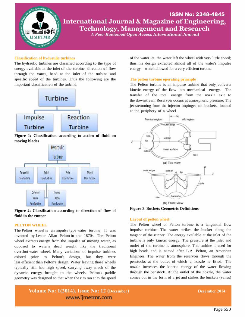
Classification of hydraulic turbines
The hydraulic turbines are classified according to the type of
energy available at the inlet of the turbine, direction of flow
through the vanes, head at the inlet of the turbine and
specific speed of the turbines. Thus the following are the
important classification of the turbine:
Figure 1: Classification according to action of fluid on
moving blades
Figure 2: Classification according to direction of flow of
fluid in the runner
PELTON WHEEL
The Pelton wheel is an impulse type water turbine. It was
invented by Lester Allan Pelton in the 1870s. The Pelton
wheel extracts energy from the impulse of moving water, as
opposed to water's dead weight like the traditional
overshot water wheel. Many variations of impulse turbines
existed prior to Pelton's design, but they were
less efficient than Pelton's design. Water leaving those wheels
typically still had high speed, carrying away much of the
dynamic energy brought to the wheels. Pelton's paddle
geometry was designed so that when the rim ran at ½ the speed
of the water jet, the water left the wheel with very little speed;
thus his design extracted almost all of the water's impulse
energy—which allowed for a very efficient turbine.
The pelton turbine operating principle
The Pelton turbine is an impulse turbine that only converts
kinetic energy of the flow into mechanical energy. The
transfer of the total energy from the nozzle exit to
the downstream Reservoir occurs at atmospheric pressure. The
jet stemming from the injector impinges on buckets, located
at the periphery of a wheel.
Figure 3: Buckets Geometric Definitions
Layout of pelton wheel
The Pelton wheel or Pelton turbine is a tangential flow
impulse turbine. The water strikes the bucket along the
tangent of the runner. The energy available at the inlet of the
turbine is only kinetic energy. The pressure at the inlet and
outlet of the turbine is atmosphere. This turbine is used for
high heads and is named after L.A. Pelton, an American
Engineer. The water from the reservoir flows through the
penstocks at the outlet of which a nozzle is fitted. The
nozzle increases the kinetic energy of the water flowing
through the penstock. At the outlet of the nozzle, the water
comes out in the form of a jet and strikes the buckets (vanes)
Page 551
of the runner. The main parts of the Pelton turbine are Nozzle
and flow regulating arrangement (spear), Runner and buckets,
Casing, and Breaking jet.
Efficiencies of turbine
The following are the important Efficiencies of a turbine.
(A) Hydraulic efficiency (ɳh)
(B) Mechanical efficiency (ɳm)
(C) Volumetric efficiency (ɳv)
(D) Overall efficiency (ɳo)
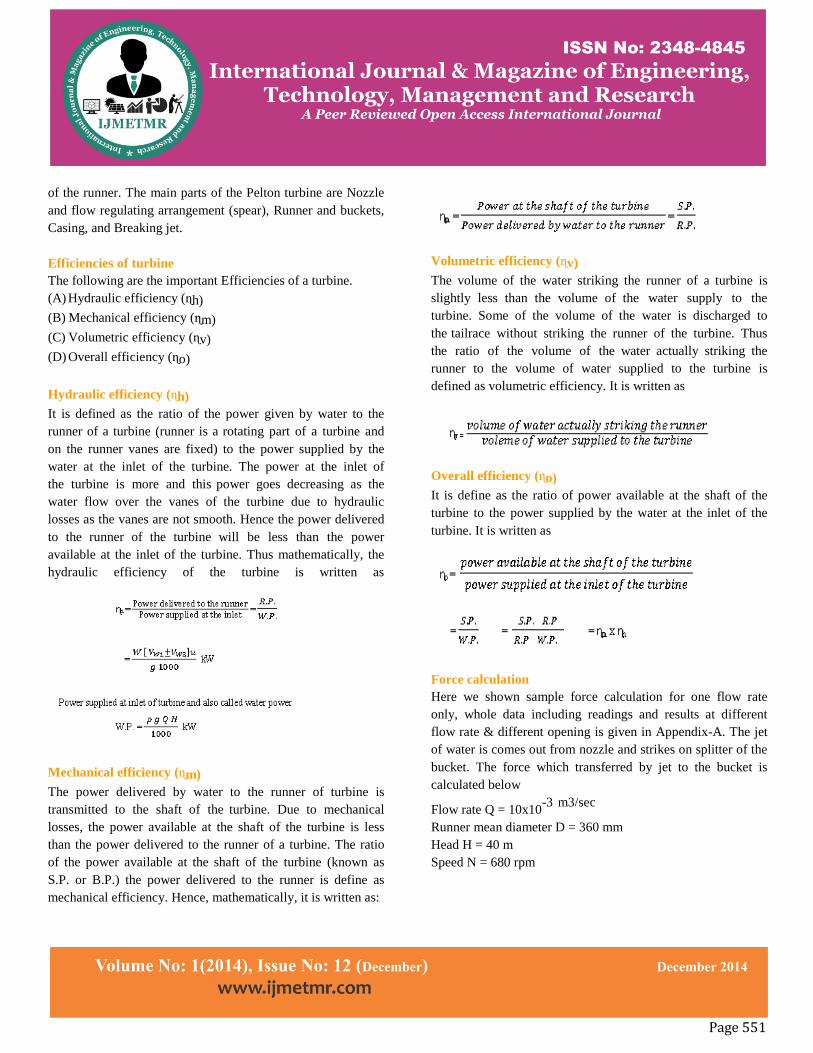
Hydraulic efficiency (ɳh)
It is defined as the ratio of the power given by water to the
runner of a turbine (runner is a rotating part of a turbine and
on the runner vanes are fixed) to the power supplied by the
water at the inlet of the turbine. The power at the inlet of
the turbine is more and this power goes decreasing as the
water flow over the vanes of the turbine due to hydraulic
losses as the vanes are not smooth. Hence the power delivered
to the runner of the turbine will be less than the power
available at the inlet of the turbine. Thus mathematically, the
hydraulic efficiency of the turbine is written as
Mechanical efficiency (ɳm)
The power delivered by water to the runner of turbine is
transmitted to the shaft of the turbine. Due to mechanical
losses, the power available at the shaft of the turbine is less
than the power delivered to the runner of a turbine. The ratio
of the power available at the shaft of the turbine (known as
S.P. or B.P.) the power delivered to the runner is define as
mechanical efficiency. Hence, mathematically, it is written as:
Volumetric efficiency (ɳv)
The volume of the water striking the runner of a turbine is
slightly less than the volume of the water supply to the
turbine. Some of the volume of the water is discharged to
the tailrace without striking the runner of the turbine. Thus
the ratio of the volume of the water actually striking the
runner to the volume of water supplied to the turbine is
defined as volumetric efficiency. It is written as
Overall efficiency (ɳo)
It is define as the ratio of power available at the shaft of the
turbine to the power supplied by the water at the inlet of the
turbine. It is written as
Force calculation
Here we shown sample force calculation for one flow rate
only, whole data including readings and results at different
flow rate & different opening is given in Appendix-A. The jet
of water is comes out from nozzle and strikes on splitter of the
bucket. The force which transferred by jet to the bucket is
calculated below
Flow rate Q = 10x10-3 m3/sec
Runner mean diameter D = 360 mm
Head H = 40 m
Speed N = 680 rpm
Page 552
Vw1 = v1-u1 = 14.773 m/sec
Vw2 = 0.85 × Vw1 = 12.55705 m/sec
Vu2 = u2 – Vw2 cos 15 = 0.68786 m/sec
So, Force applied by jet on bucket
Fu = ρ × Q × (Vu1-Vu2)
= (Vu1 – Vu2)
= 26.912
Fu = 269 N
MODELING OF PELTON WHEEL
Solid works
Solid Works is mechanical design automation software that
takes advantage of the familiar Microsoft Windows graphical
user interface. It is an easy-to-learn tool which makes it
possible for mechanical designers to quickly sketch ideas,
experiment with features and dimensions, and produce models
and detailed drawings.
Introduction to solid works
Solidworks mechanical design automation software is a
feature-based, parametric solid modeling design tool which
advantage of the easy to learn windows graphical user
interface. We can create fully associate 3-D solid models with
or without while utilizing automatic or user defined relations
to capture design intent. Parameters refer to constraints whose
values determine the shape or geometry of the model or
assembly. Parameters can be either numeric parameters, such
as line lengths or circle diameters, or geometric parameters,
such as tangent, parallel, concentric, horizontal or vertical, etc.
Numeric parameters can be associated with each other through
the use of relations, which allow them to capture design intent.
Layer-cake approach
The layer-cake approach builds the part one piece at a time,
adding each layer, or feature, onto the previous one.
Potter’s wheel approach
The potter’s wheel approach builds the part as a single
revolved feature. As a single sketch representing the cross
section includes all the information and dimensions necessary
to make the part as one feature.
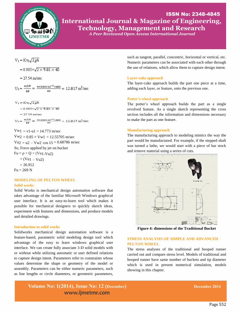
Manufacturing approach
The manufacturing approach to modeling mimics the way the
part would be manufactured. For example, if the stepped shaft
was turned a lathe, we would start with a piece of bar stock
and remove material using a series of cuts.
Figure 4: dimensions of the Traditional Bucket
STRESS ANALYSIS OF SIMPLE AND ADVANCED
PELTON WHEEL
The stress analyses of the traditional and hooped runner
carried out and compare stress level. Models of traditional and
hooped runner have same number of buckets and tip diameter
which is used in present numerical simulation, models
showing in this chapter.
Page 553
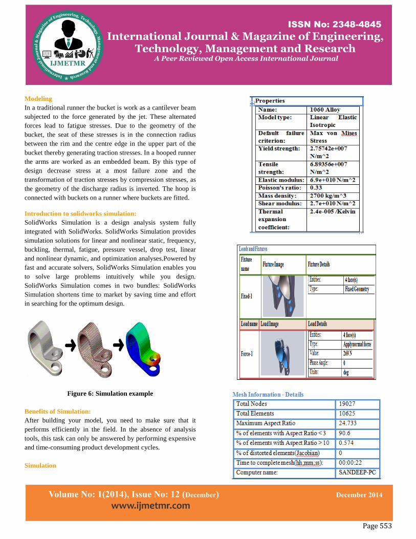
Modeling
In a traditional runner the bucket is work as a cantilever beam
subjected to the force generated by the jet. These alternated
forces lead to fatigue stresses. Due to the geometry of the
bucket, the seat of these stresses is in the connection radius
between the rim and the centre edge in the upper part of the
bucket thereby generating traction stresses. In a hooped runner
the arms are worked as an embedded beam. By this type of
design decrease stress at a most failure zone and the
transformation of traction stresses by compression stresses, as
the geometry of the discharge radius is inverted. The hoop is
connected with buckets on a runner where buckets are fitted.
Introduction to solidworks simulation:
SolidWorks Simulation is a design analysis system fully
integrated with SolidWorks. SolidWorks Simulation provides
simulation solutions for linear and nonlinear static, frequency,
buckling, thermal, fatigue, pressure vessel, drop test, linear
and nonlinear dynamic, and optimization analyses.Powered by
fast and accurate solvers, SolidWorks Simulation enables you
to solve large problems intuitively while you design.
SolidWorks Simulation comes in two bundles: SolidWorks
Simulation shortens time to market by saving time and effort
in searching for the optimum design.
Figure 6: Simulation example
Benefits of Simulation:
After building your model, you need to make sure that it
performs efficiently in the field. In the absence of analysis
tools, this task can only be answered by performing expensive
and time-consuming product development cycles.
Simulation
Page 554
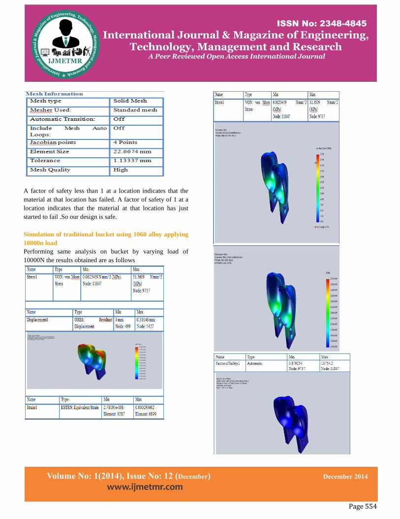
A factor of safety less than 1 at a location indicates that the
material at that location has failed. A factor of safety of 1 at a
location indicates that the material at that location has just
started to fail .So our design is safe.
Simulation of traditional bucket using 1060 alloy applying
10000n load
Performing same analysis on bucket by varying load of
10000N the results obtained are as follows
Page 555
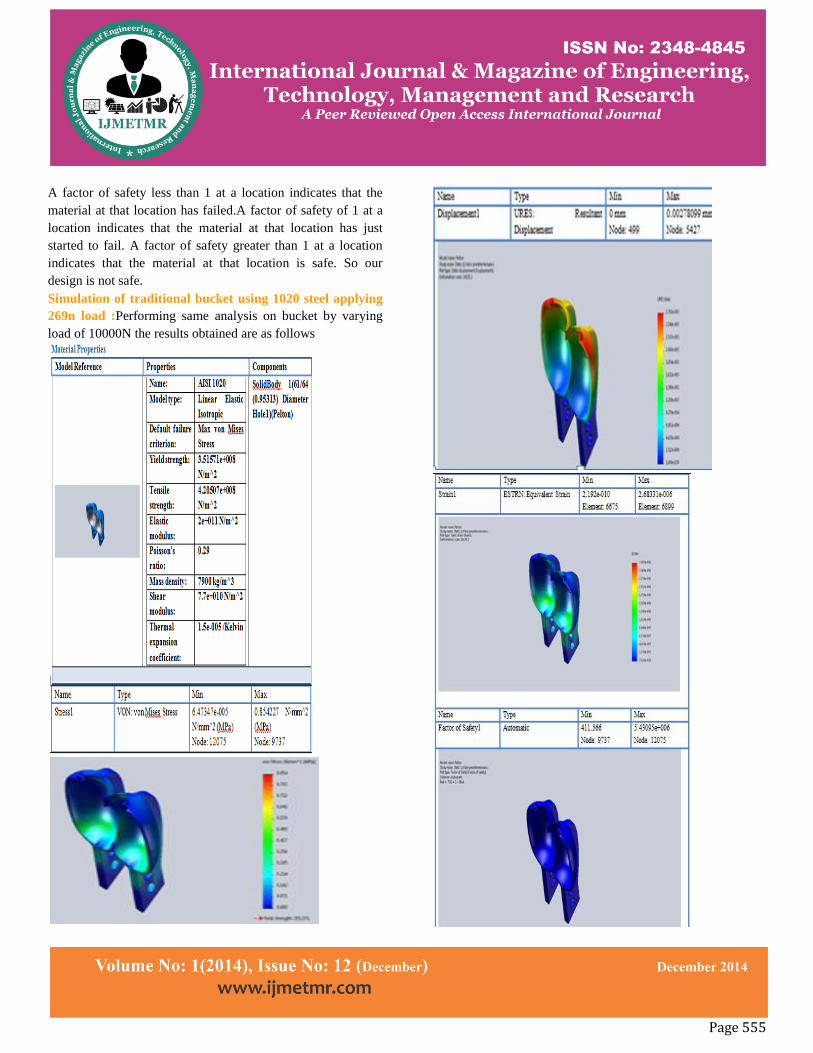
A factor of safety less than 1 at a location indicates that the
material at that location has failed.A factor of safety of 1 at a
location indicates that the material at that location has just
started to fail. A factor of safety greater than 1 at a location
indicates that the material at that location is safe. So our
design is not safe.
Simulation of traditional bucket using 1020 steel applying
269n load :Performing same analysis on bucket by varying
load of 10000N the results obtained are as follows
Page 556
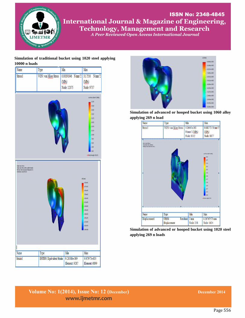
Simulation of traditional bucket using 1020 steel applying
10000 n loads
Simulation of advanced or hooped bucket using 1060 alloy
applying 269 n load
Simulation of advanced or hooped bucket using 1020 steel
applying 269 n loads
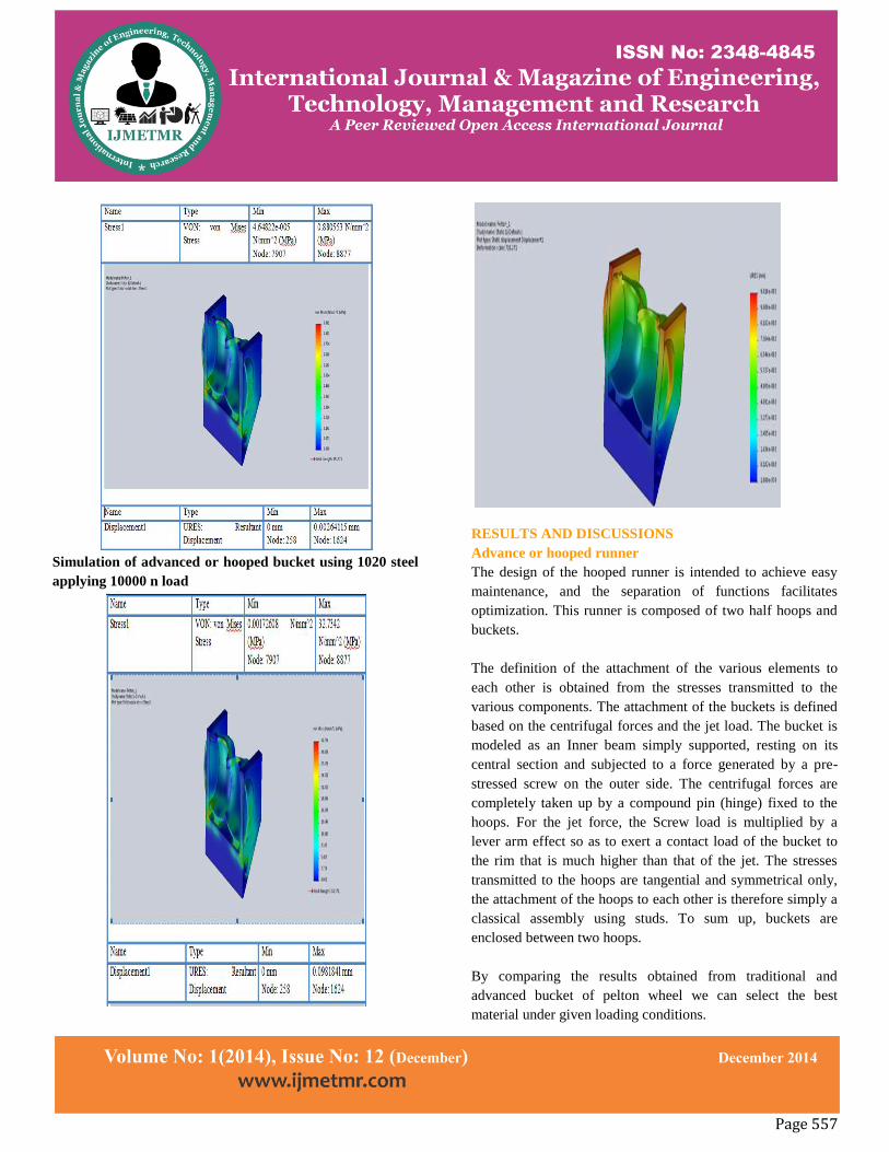
Page 557
Simulation of advanced or hooped bucket using 1020 steel
applying 10000 n load
RESULTS AND DISCUSSIONS
Advance or hooped runner
The design of the hooped runner is intended to achieve easy
maintenance, and the separation of functions facilitates
optimization. This runner is composed of two half hoops and
buckets.
The definition of the attachment of the various elements to
each other is obtained from the stresses transmitted to the
various components. The attachment of the buckets is defined
based on the centrifugal forces and the jet load. The bucket is
modeled as an Inner beam simply supported, resting on its
central section and subjected to a force generated by a pre-
stressed screw on the outer side. The centrifugal forces are
completely taken up by a compound pin (hinge) fixed to the
hoops. For the jet force, the Screw load is multiplied by a
lever arm effect so as to exert a contact load of the bucket to
the rim that is much higher than that of the jet. The stresses
transmitted to the hoops are tangential and symmetrical only,
the attachment of the hoops to each other is therefore simply a
classical assembly using studs. To sum up, buckets are
enclosed between two hoops.
By comparing the results obtained from traditional and
advanced bucket of pelton wheel we can select the best
material under given loading conditions.
Page 558
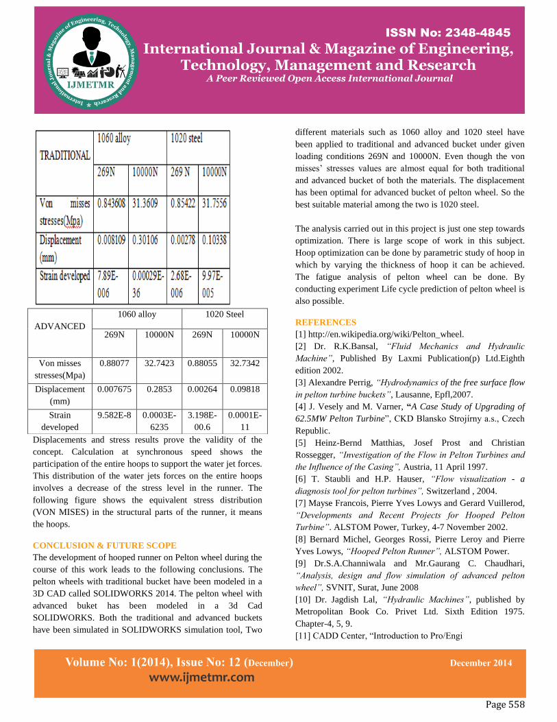
Displacements and stress results prove the validity of the
concept. Calculation at synchronous speed shows the
participation of the entire hoops to support the water jet forces.
This distribution of the water jets forces on the entire hoops
involves a decrease of the stress level in the runner. The
following figure shows the equivalent stress distribution
(VON MISES) in the structural parts of the runner, it means
the hoops.
CONCLUSION & FUTURE SCOPE
The development of hooped runner on Pelton wheel during the
course of this work leads to the following conclusions. The
pelton wheels with traditional bucket have been modeled in a
3D CAD called SOLIDWORKS 2014. The pelton wheel with
advanced buket has been modeled in a 3d Cad
SOLIDWORKS. Both the traditional and advanced buckets
have been simulated in SOLIDWORKS simulation tool, Two
different materials such as 1060 alloy and 1020 steel have
been applied to traditional and advanced bucket under given
loading conditions 269N and 10000N. Even though the von
misses’ stresses values are almost equal for both traditional
and advanced bucket of both the materials. The displacement
has been optimal for advanced bucket of pelton wheel. So the
best suitable material among the two is 1020 steel.
The analysis carried out in this project is just one step towards
optimization. There is large scope of work in this subject.
Hoop optimization can be done by parametric study of hoop in
which by varying the thickness of hoop it can be achieved.
The fatigue analysis of pelton wheel can be done. By
conducting experiment Life cycle prediction of pelton wheel is
also possible.
REFERENCES
[1] http://en.wikipedia.org/wiki/Pelton_wheel.
[2] Dr. R.K.Bansal, “Fluid Mechanics and Hydraulic
Machine”, Published By Laxmi Publication(p) Ltd.Eighth
edition 2002.
[3] Alexandre Perrig, “Hydrodynamics of the free surface flow
in pelton turbine buckets”, Lausanne, Epfl,2007.
[4] J. Vesely and M. Varner, “A Case Study of Upgrading of
62.5MW Pelton Turbine‖, CKD Blansko Strojírny a.s., Czech
Republic.
[5] Heinz-Bernd Matthias, Josef Prost and Christian
Rossegger, “Investigation of the Flow in Pelton Turbines and
the Influence of the Casing”, Austria, 11 April 1997.
[6] T. Staubli and H.P. Hauser, “Flow visualization - a
diagnosis tool for pelton turbines”, Switzerland , 2004.
[7] Mayse Francois, Pierre Yves Lowys and Gerard Vuillerod,
“Developments and Recent Projects for Hooped Pelton
Turbine”. ALSTOM Power, Turkey, 4-7 November 2002.
[8] Bernard Michel, Georges Rossi, Pierre Leroy and Pierre
Yves Lowys, “Hooped Pelton Runner”, ALSTOM Power.
[9] Dr.S.A.Channiwala and Mr.Gaurang C. Chaudhari,
“Analysis, design and flow simulation of advanced pelton
wheel”, SVNIT, Surat, June 2008
[10] Dr. Jagdish Lal, “Hydraulic Machines”, published by
Metropolitan Book Co. Privet Ltd. Sixth Edition 1975.
Chapter-4, 5, 9.
[11] CADD Center, ―Introduction to Pro/Engi
ADVANCED
1060 alloy 1020 Steel
269N 10000N 269N 10000N
Von misses
stresses(Mpa)
0.88077 32.7423 0.88055 32.7342
Displacement
(mm)
0.007675 0.2853 0.00264 0.09818
Strain
developed
9.582E-8 0.0003E-
6235
3.198E-
00.6
0.0001E-
11