DESIGN AND ANALYSIS OF MECHANICAL MATING INTERFACES …
43
DESIGN AND ANALYSIS OF MECHANICAL MATING INTERFACES FOR RECONFIGURABLE MACHINE TOOLS NORMARIAH BINTI CHE MAIDEEN UNIVERSITI SAINS MALAYSIA 2010
Transcript of DESIGN AND ANALYSIS OF MECHANICAL MATING INTERFACES …
DESIGN AND ANALYSIS OF MECHANICAL MATING INTERFACES FOR
RECONFIGURABLE MACHINE TOOLS
NORMARIAH BINTI CHE MAIDEEN
UNIVERSITI SAINS MALAYSIA 2010

DESIGN AND ANALYSIS OF MECHANICAL MATING INTERFACES FOR
RECONFIGURABLE MACHINE TOOLS
by
NORMARIAH BINTI CHE MAIDEEN
Thesis submitted in fulfilment of the requirements for the degree
of Master of Science
November 2010

ii
ACKNOWLEDGEMENT
The author would like to express her thanks to:
Associate Professor Dr. Zaidi Mohd Ripin for permitting this work to be
carried out in the School of Mechanical Engineering.
Her supervisor, Associate Professor Dr. Indra Putra Almanar for his
thoughtful supervision, steady support, guidance, and critics throughout the
completion of the research work.
Dr. Mohd Salman Bin Abu Mansor, Dr. Amir Yazid Bin Ali, Assoc. Prof. Ir.
Shuib Bin Sahudin, and Dr. Zuhailawati Hussain for their comments to
improve the dissertation and content of the research work.
Universiti Sains Malaysia for the financial support given under fellowship
scheme.
Finally, special thanks to my family and colleagues for their support and
motivations.
iii
TABLE OF CONTENTS
ACKNOWLEDGEMENT ii
TABLE OF CONTENTS iii
LIST OF TABLES vii
LIST OF FIGURES viii
LIST OF SYMBOLS xi
LIST OF ABBREVIATIONS xii
LIST OF APPENDIXES xiii
LIST OF PUBLICATIONS xiv
ABSTRAK xv
ABSTRACT xvii
CHAPTER 1: INTRODUCTION
1.1 Background 1
1.2 Roles of Reconfigurable Machine Tools (RMTs) in RMS 2
1.3 The Construction of RMTs 3
1.4 Problem Statement 6
1.5 Research Objectives 9
1.6 Thesis Outline 9
CHAPTER 2: LITERATURE REVIEW
2.1 Developed Reconfigurable Machine Tools (RMTs) 11
2.2 Design Principles and Methods of RMTs 15
2.3 Functional Requirements of Machine Modules in RMT 22

iv
2.4 Relevant Design for Mechanical Mating Interface 25
2.4.1 Precision Coupling 28
2.4.2 Spindle Tool Holder 35
2.5 Methods to Evaluate the Performance of Mechanical Mating Interfaces 37
2.6 Literature Findings 38
2.7 Summary 40
CHAPTER 3: DESIGN AND ANALYSIS OF MECHANICAL MATING INTERFACES
3.1 Overview 41
3.2 Step 1: Function Analysis 42
3.3 Step 2: Concept Generation, Evaluation, and Selection 45
3.3.1 First Functional Requirement 45
3.3.2 Second Functional Requirement 47
3.3.3 Third Functional Requirement 47
3.4 Step 3: Conceptual Design 49
3.4.1 Arrangement of Two Non-vertex Cones 49
3.4.2 Pin-slot Arrangement 52
3.5 Step 4: Detail Design 53
3.5.1 Geometric Generation 53
3.5.1.1 Dependent variables 55
3.5.1.2 Independent variables 58
3.5.2 One Dimensional (1D) Tolerance Stack-up Analysis 74
3.5.2.1 Established performance/assembly requirement 74
3.5.2.2 Construct vector loop diagram 74
3.5.2.3 Identify fixed or variable properties and identify machining
v
process 75
3.5.2.4 Mean value (gap) for the requirement 75
3.5.2.5 Determine method of analysis 76
3.5.2.6 Solving for proportionality factor, P 77
3.5.2.7 Re-allocated tolerance for each component 77
3.5.2.8 Re-calculate the expected variation of the clearance 78
CHAPTER 4: CASE STUDY: SPINDLE – GEAR-BOX ASSEMBLY
4.1 Modelling of Spindle-Gear-box Assembly 79
4.1.1 Dependent Variables 80
4.1.2 Independent Variables 83
4.1.2.1 Finite Element modelling 84
4.2 Simulation of Spindle-Gear-box Assembly 87
4.2.1 Performance Comparison between Model A and Model B 88
4.2.2 Performance Comparison between Model B and Model C 97
4.3 One Dimensional (1D) Tolerance Stack-up Analysis 99
CHAPTER 5: CONCLUSIONS AND RECOMMENDATIONS
5.1 Conclusions 106
5.2 Recommendations 107
REFERENCES 108
PUBLICATIONS 113

vi
APPENDIXES
Appendix - A Patent A-1
Appendix - B Example of Standard Size for a Pin B-1
Appendix - C Example of Machine Specification C-1
vii
LIST OF TABLES
Page
Table 2.1 Summary of the functional requirements of the machine modules in RMTs
25
Table 3.1 Number of DOF being constrained 45
Table 3.2 Summary of concept specifications 48
Table 3.3 Variables and levels used in the study 63
Table 3.4 The combinations of each variable at each level 63
Table 3.5 Mechanical properties of mild steel 64
Table 3.6 Interaction properties of assembled modules 66
Table 3.7 Percentage of error of FEA model compare to experimental work
71
Table 4.1 Mechanical properties of all models 86
Table 4.2 Difference of mating interfaces separation between model A and model B
93
Table 4.3 Information regarding dimensions in vector loop diagram 102

viii
LIST OF FIGURES
Page
Figure 1.1 Separation of two bolted joint flat surfaces of spindle-gear-box assembly due to static loading
8
Figure 2.1 Full scale prototype of Arch-Type RMT 12
Figure 2.2 Full scale prototype of METEOR 14
Figure 2.3 Concurrent design methodology 18
Figure 2.4 Modular reconfigurability design methodology 19
Figure 2.5 Research and engineering development subjects of bolted joint in machine tools
27
Figure 2.6 Comparison of the practical performance limits of mentioned couplings
29
Figure 2.7a Ball-groove kinematic coupling arrangement 31
Figure 2.7b Stability configuration of three balls and three grooves in triangle form
31
Figure 2.8 ABB IRB6400R industrial robot manipulator 32
Figure 2.9 Canoe ball coupling 32
Figure 2.10 Three-pin coupling 33
Figure 2.11 Quasi kinematic coupling 34
Figure 2.12 Design matrix for mating surfaces 36
Figure 3.1 Flow chart of research methodology 42
Figure 3.2 FAST on the mating interface requirement 44
Figure 3.3 Concentricity assurance in the assembly of male-female mating interface
49
Figure 3.4 Balanced male-female mating interface assembly 50
Figure 3.5 Balanced and larger amount of contact surfaces 52
Figure 3.6 Pin-slot arrangement 52
Figure 3.7 Conceptual design of mechanical mating interface for RMTs 53
Figure 3.8 Design variables of male-female mating interfaces 54
Figure 3.9 Diameter of the outer non-vertex cone for square shape of mating interface
56
ix
Figure 3.10 Diameter of the outer non-vertex cone for circle shape of mating interface
57
Figure 3.11 Schematic construction of a bolted column of a radial drilling machine (B type)
60
Figure 3.12 (a) Bolted joint with two flat surfaces (model 1) and (b) bolted joint with newed design mating interface (model 2)
62
Figure 3.13 Location of preload force 65
Figure 3.14 Interaction of column to base for model 1 67
Figure 3.15 Interaction of column to base for model 2 67
Figure 3.16 Interaction of washer to column 68
Figure 3.17 Boundary condition and static load applied to the column-base assembly
69
Figure 3.18 Comparison between FEA and experimental result 71
Figure 3.19 General behavior of static stiffness of column-base structure due to static loading at 5 mm from tip of the column
72
Figure 3.20 Static stiffness of new designed of mechanical mating models simulated using FEA
73
Figure 4.1 Full assembly of spindle-gear-box modules 80
Figure 4.2 Dimension of spindle-gear-box assembly 81
Figure 4.3 Dimensions of dependent variables of (a) male and (b) female mating interface
82
Figure 4.4 Detail dimension of newly designed mating interfaces 83
Figure 4.5 3D model of (a) Bolted joint of two flat surfaces (model A), (b) Bolted joint of newly designed mating interfaces (model B), and (c) Bolted joint of newly designed mating interfaces with through hole at both mating interfaces (model C)
85
Figure 4.6 Boundary condition and static loading position for all models 87
Figure 4.7 Comparison of bending stiffness between model A and model B
88
Figure 4.8 Bolt elongation of (a) model A and (b) model B 90
Figure 4.9 Bolt elongation in model A due to (a) 280 kN and (b) 300 kN static loading
91
Figure 4.10 Bolt elongation in model B due to (a) 280 kN and (b) 300 kN static loading
92

x
Figure 4.11 Physical effect of mating interfaces due to 300 kN of static loading for (a) model A and (b) model B
94
Figure 4.12 Maximum stress of (a) model A and (b) model B when the load applied is 300 kN
96
Figure 4.13 Stress distribution in model B when 300 kN is applied 97
Figure 4.14 Comparison of stiffness value between model B and model C 98
Figure 4.15 Cross-section taken for 1D tolerance stack-up analysis consideration
100
Figure 4.16 Vector loop diagram of newly design mating interfaces 101
Figure 4.17 Mating side of (a) male and (b) female mating interfaces 104
Figure 4.18 Orientation of male and female mating interface just before assembly
105

xi
LIST OF SYMBOLS
Angle of non-vertex inner cone
Angle of non-vertex outer cone
a Face clearance between male and female at initial assembly
dm Depth of penetration of the male interface into the female interface
Fi Bolt preload
At Tensile stress area
Sp Proof strength
tg Tolerance for gap value
dg Mean gap value of the clearance
n Number of dimensions involve in the stackup
ai Sensitivity
di Nominal value of the ith dimension in the loop diagram
trss Assembly tolerance using RSS method
ti Tolerance value of the dimensions in the loop diagram
Proportionality factor
tfn Tolerance value that has n fixed property
tvn Tolerance value that has n variable property
tn New tolerance value of particular dimension
xii
LIST OF ABBREVIATIONS
RMS Reconfigurable Manufacturing System
FMS Flexible Manufacturing System
RMTs Reconfigurable Machine Tools
METEOR MEhr TEchnologie Orientierte Rekonfigurierbare
DMT Dedicated Machine Tools
CNC Computer Numerical Control
MIT Massachusetts Institute of Technology
PREMADE Program for REconfigurable Machine tool Design
FEM Finite Element Method
CAD Computer Aided Design
MDO Multidisciplinary Design Optimization
HSK Hollow Shank Kegel
PERG Precision Engineering Research Group
PSDAM Precision Systems Design and Manufacturing Group
DOF Degree of Freedom
FEA Finite Element Analysis

xiii
LIST OF APPENDIXES
Page
A Patent A-1
B Example of Standard Size for a Pin B-1
C Example of Machine Specification C-1
xiv
LIST OF PUBLICATIONS
1. An Improved Mechanical Mating Interface Apparatus for Reconfigurable
Machine Tool
2. Mating Interface Methods of Assembled Modules in Reconfigurable
Machine Tool
3. Ergonomic Assessment Factors in Reconfigurable Assembly Workplace
4. Mechanical Assemblies Design of Underwater Electric Motor
5. Tolerance Allocation for Mechanical Assemblies of AC Brushless High
Speed Electric Mini Motor

xv
REKABENTUK DAN ANALISA
PERTEMUAN MEKANIKAL ANTARA MUKA BAGI
ALATAN MESIN BOLEH UBAH
ABSTRAK
Alatan mesin boleh ubah yang direkabentuk mengikut konsep bermodul
adalah merupakan kaedah baru di dalam teknologi alatan mesin. Mempunyai ciri-
ciri yang spesifik tetapi fleksible, menjadikan kaedah baru ini mampu untuk
menyediakan kehendak pengeluaran semasa. Ia membenarkan perubahan
konfigurasi fizikal mesin apabila diperlukan. Konsep alatan mesin ini masih lagi di
bawah fasa pembangunan. Walaupun terdapat beberapa kaedah rekabentuk telah di
cadangkan, tetapi masih belum ada kaedah rekabentuk yang menjelaskan bagaimana
setiap modul yang terlibat perlu disambungkan bersama. Menggunakan kaedah
rekabentuk berstruktur, rekabentuk baru bagi pertemuan antara muka secara
mekanik dicadangkan. Dua kon tanpa bucu bersama aturan pin-lubang alur telah
dikenalpasti sebagai konsep yang terbaik. Menggunakan kaedah unsur takterhingga,
rekabentuk terperinci dapat diketahui melalui kombinasi optimum bagi
pembolehubah di dalam rekabentuk. Kekakuan sambungan yang baik dapat
diperolehi apabila nisbah kedalaman kemasukan kon terhadap tebal keseluruhan
antara muka adalah 0.6. Sudut 1/10 adalah nilai yang terbaik bagi kon dan 0.15 mm
nilai bagi kelegaan-muka di antara pertemuan antara muka telah menjamin nilai
pemasangan gangguan sebanyak 5µm. Menggunakan simulasi model, prestasi
rekabentuk baru bagi pertemuan antara muka telah dikaji dan dibandingkan dengan
kaedah lama antara muka. Hasil perbandingan menunjukkan bahawa prestasi

xvi
rekabentuk baru bagi pertemuan antara muka adalah lebih baik berbanding kaedah
lama. Akhir sekali, analisa had-terima dilakukan dan nilai had-terima yang paling
sesuai diberikan kepada rekabentuk. Dengan ini, pemasangan gangguan yang
dikehendaki di dalam sambungan tercapai.
xvii
DESIGN AND ANALYSIS OF MECHANICAL MATING INTERFACES
FOR RECONFIGURABLE MACHINE TOOLS
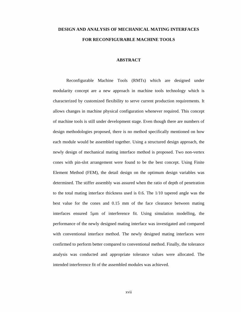
ABSTRACT
Reconfigurable Machine Tools (RMTs) which are designed under
modularity concept are a new approach in machine tools technology which is
characterized by customized flexibility to serve current production requirements. It
allows changes in machine physical configuration whenever required. This concept
of machine tools is still under development stage. Even though there are numbers of
design methodologies proposed, there is no method specifically mentioned on how
each module would be assembled together. Using a structured design approach, the
newly design of mechanical mating interface method is proposed. Two non-vertex
cones with pin-slot arrangement were found to be the best concept. Using Finite
Element Method (FEM), the detail design on the optimum design variables was
determined. The stiffer assembly was assured when the ratio of depth of penetration
to the total mating interface thickness used is 0.6. The 1/10 tapered angle was the
best value for the cones and 0.15 mm of the face clearance between mating
interfaces ensured 5µm of interference fit. Using simulation modelling, the
performance of the newly designed mating interface was investigated and compared
with conventional interface method. The newly designed mating interfaces were
confirmed to perform better compared to conventional method. Finally, the tolerance
analysis was conducted and appropriate tolerance values were allocated. The
intended interference fit of the assembled modules was achieved.

1
CHAPTER 1
INTRODUCTION
First chapter is written and structured in six sections as to provide general
information about the work that has been conducted. In the first section of the first
chapter, the theoretical foundations of this work are presented and further elaborated
subsequently in the sections that discuss the role of reconfigurable machine tools and
their performance requirements as the machine in a new manufacturing environment
called Reconfigurable Manufacturing System (RMS). The necessity of having suitable
mechanical mating interfaces are stated in the problem statement section, followed by
the establishment of research objectives. An overview of the structure of the thesis is
given in the final section.
1.1 Background
Today’s manufacturing system has to deal with turbulent and quickly changing
business environment, which are manifested in shorter product life cycles, unpredictable
demand, and customized products that have forced manufacturing systems to operate
more efficiently and effectively. However, traditional manufacturing systems, such as
job shops and flow lines, cannot handle this kind of environment because they are not
flexible enough for the changes. Only Flexible Manufacturing System (FMS) is suitable
for this kind of environment, but the high initial capital cost is considered as the
disadvantage. For that reasons a new approach in manufacturing system called
Reconfigurable Manufacturing System (RMS) was introduced at the Engineering
2
Research Center of the University of Michigan in the mid 1990s (Koren, 2006). The
characteristics of the proposed system are: modularity, integrability, convertability,
diagnosability, customization, and scalability. The more of these characteristics are
possessed by a manufacturing system, the more reconfigurable it becomes.
Over the last few years, considerable efforts have been made to develop and
implement the RMS that is believed could provide a cost effective answer to the new
business environment. This new system provides the functionality, which is available
when it is needed. This could be achieved through rapid scaling of capacity and
functionality, in response to new requirements, by rearranging or changing its
components. The RMS components could be classified as physical components
(machine, tooling, fixture, etc) and logical components (programs, control, plan, etc)
(Mehrabi et al., 2000). Out of those components, machine tools are the key principle for
the reconfiguration of the manufacturing systems (Wiendahl et al., 2007). As illustrated
by Abele et al. (2007), a typical RMS consists of a number of Reconfigurable Machine
Tools (RMTs). Until today however, there are two prototypes of RMTs that have been
developed: the Arch Type RMT and MEhr TEchnologie Orientierte Rekonfigurierbare
(METEOR). Both RMTs are still under research and development and there are no
commercial reconfigurable machine tools available yet.
1.2 Roles of Reconfigurable Machine Tools (RMTs) in RMS
Common type of machine tools in large manufacturing industries today is the
Dedicated Machine Tool (DMT). This type of machine is specifically designed for a
single part that would be mass produced. It can perform a unique operation with high

3
reliability, high repeatability and high productivity. As the result, its structures are
relatively simple and its cost is always less expensive. However it is not cost-effectively
converted when parts to be produced are changed. To address this challenge, flexible
CNC machine tools has been developed and used in many industries. The machine
should perform multiple operations with high reliability, repeatability and productivity
as dedicated machine do. Due to the reason of redundant flexibilities and over
capabilities, they often have wasted resources that make users pay for features they do
not need. These challenges left the option to adopt the DMT approach and design the
machine that can be reconfigured around part family or a set of parts (rather than a
specific part), so conversion by rapid reconfiguration of the machine can be made
possible. To drive the machine, CNC technology is used. This hybrid type of machine,
which is known as Reconfigurable Machine Tool (RMT), has therefore a customized
flexibility that makes it less expensive than general-purpose CNCs.
1.3 The Construction of RMTs
To achieve the goals set in RMS (modularity, integrability, convertability,
diagnosability, customization, and scalability), modularity should be the key
characteristic for the construction of RMTs. Although modular machine tools have been
on the market for several years, they do not satisfy the modularity required by RMTs,
because the configuration of the modules have already been predetermined during the
design stage. However, some theory in published articles on modular machines,
modular robots and assemblies are relevant to the modularity concept of RMTs. For
example, Ito (2008) demonstrated how the modularity concept is implemented in

4
designing a modular machine tool. However he did not discuss how the modularity of
machine tool structure could be re-configured. Research on modular robot and
assemblies conducted by Massachusetts Institute of Technology (MIT) introduced
kinematic coupling concept to improve the technology in precision assembly of
modular robot, instrumentation structures, and engine’s assembly process (Culpepper,
2000; Culpepper, 2004; Willoughby et al., 2005 and Hart et al., 2004). However, the
modularity is only applicable for the modification of structural dimension of wrist and
relocation of the robot base where the robot itself is not re-configurable.
In general, RMTs are made up of various exchangeable modules that can be
configured and reconfigured to performed functions as required. Thus, in order to
perform the intended function, RMTs undergo topological changes, i.e. size, type and
number of modules and their interconnections (Moon and Kota, 2002). The degree of
modularity is measured by the ability of the modules to be integrated (integrability), to
be modified due to the system’s functionality (convertibility), to be adapted to other
functional modules (scalability), and to be dedicated for a given part family
(customization) (Abele et al., 2007). As a whole, the mentioned degree of modularity is
meaningless if the performance of the developed RMTs is worse than existing types of
DMTs or FMSs.
Since RMTs were introduced, a number of relevant researches have been
conducted, initiated with the study on the performance requirements of RMTs that were
discussed by Landers et al. (2001). Researches grow with the establishment of
principles and structured design methodologies (Katz and Moon, 2000; Moon, 2006;
Riba et al., 2005; Ahuett et al., 2005; Abele et al., 2007; Katz, 2007; Jang et al., 2008;
5
Mpofu et al., 2008; and Bi and Wang, 2009) together with the optimization on the
RMTs design as introduced by Liang and Lie (2007). They established a method to
optimize the design by using modified fuzzy-Chebyshev programming approach.
Lorenzed et al. (2007) introduced a modeling and evaluation tools for supporting
decisions of the design. A year later, Xing et al. (2008) introduced the application of
mechatronic design approach in design and optimization of RMTs. However, the most
challenging task in developing RMTs is to ensure that the dimensional and geometric
accuracies are maintained each time a new configuration takes place, so that the lengthy
and expensive setting up and re-calibration procedures could be avoided. Since the
RMTs are made in modular forms, the most critical factor that will influenced the
machine tools accuracy is the mechanical interfaces between two or more assembled
modules. The failure to accurately position the RMTs modules relative to each other
will affects the positioning accuracy of the tool relative to the work piece. As discussed
by Abele et al. (2007), the positioning error is caused by static and dynamic stiffness.
Previously, Yigit and Ulsoy (2002) have developed a systematic methodology to
evaluate the RMT structural stiffness.
In modular machine tools, each module is developed and fabricated separately
and will be assembled according to the predefined function and specification at the
predefined dimensional and geometric accuracies. Every time a set of machine’s
modules are assembled to its predefined configuration, a set of predefined dimensional
and geometric accuracies must be achieved. It is a lengthy and expensive process
especially when a precision machine is built since a lot of fine adjustments and
calibrations should be carried out by highly qualified technicians using highly accurate

6
instruments. Once the machine is assembled, any disturbances on the setup will require
another fine adjustment and re-calibration. This is an uneconomical task to perform.
One invented method in machine tools re-configuration was made by Koren et
al. (1997) published in US patent as US-5943750A: Reconfigurable Machine Tool.
They proposed a method that allows rapid changes in the machine structure and rapid
transformation of the machine function by relocating its basic building blocks to the
required new configuration. In the patent, workpiece is secured onto a table that
includes support units that can carry at least one unit of single-axis spindle. The re-
configuration is achieved when the spindle units can be mounted and re-mounted easily
from one support to another. However, they did not explain how repeatable accuracies
of the spindle mounting could be achieved when it is moved from one support to
another. They also did not mention what type of mounting interface they are using to
achieve various repeatable configurations. In other publication, Katz (2007) mentioned
about the positioning block that are attached to the arch plate and bolted joint to have
better structural rigidity and precision. However, the information about the repeatability
of dimensional and geometric accuracies of the positioning block and the joints are not
specifically disclosed.
1.4 Problem Statement
The dimensional and geometric accuracies are the important factors in order to
gain the predefined accuracies of the reconfigurable systems when they are assembled
into one of possible available configurations, or re-assembled into a different possible
available configuration.

7
The most important performance requirement of modular RMTs are the
repeatability of squareness, parallelity and concentricity of functional axes of the
machine modules that support the tool axis in its relationship with the axes of table
module that is used to carry the workpiece or vice versa. Moreover, in modular RMTs,
there is a need to ensure that all possible factors that contribute to the alignment errors
are eliminated.
Since the RMTs consist of modules that should be assembled or reassembled,
there is a probability that errors occur if the properties of the assembly are wrong. The
stiffness of the machine will be lost and the tool/module’s chatter will destroy the
quality of finished product. As the assembly of the machine modules is usually
involving two flat surfaces tightened by bolts, there is a possibility that the two bolted
flat surfaces will be slipping due to the separation of deformed flat surfaces. Figure 1.1
shows an example of the separation that occurs in spindle - gear box assembly due to
static loading. However, the problem can be solved by increasing the contact area
between two mating surfaces. It will make the joint becomes stiffer.
Although bolt-and-nut is a common method to join modules, the setup to attain a
required geometric accuracy is difficult to achieve because the modules will be
deformed when the bolts and nuts are tightened. Also, when cantilever assembly is
made, the weight of the cantilevered module will create positional inaccuracy of the
assembly since tolerance must be given to the bolts and their corresponding mounting
holes. Thus, suitable mating interface between the two assembled modules should be
provided. They should be able to provide accurate repeatable and interchangeable
mating interfaces. Without the capability to provide a repeatable configuration and re-

8
configuration, the concept of modular RMTs is not achieved. Apart from that, the
mating interfaces should provide good stiffness to ensure the stability of the machine
structure. Also, a quick change of modules can make to RMTs become more efficient
and economical.
Separation
Static loading
Spindle module
Bolted joints
Figure 1.1: Separation of two bolted joint flat surfaces of spindle – gear-box
assembly due to static loading
9
1.5 Research Objectives
To provide solutions on the problems stated in the previous section, a series of
objectives is established. The series contains steps as follows:
1. To establish the conceptual design by using Functional Analysis System
Technique (FAST) followed by design matrix for mating surfaces,
2. To develop detail design from the conceptual design followed by performance
verification,
3. To allocate the design tolerance of newly designed mating interfaces method for
fabrication process.
1.6 Thesis Outline
The thesis contains of five chapters. Chapter 1 provides the overview of the
current scenario in manufacturing industries that require a new type of machine tools
that are called Reconfigurable Machine Tools (RMTs). Then, the existing researches on
RMTs were briefly reviewed to show the importance of this research. Problem
statement section provides an explanation on the performance requirements of
mechanical mating interfaces in RMTs and the problems with conventional method,
which are not relevant anymore for RMTs applications. Chapter 2 provides the reviews
on the available literatures which encompass development, ideas and methods of RMTs
from researchers in machine tool area. This chapter also provides information on tools
and techniques that are relevant to designing suitable mating interface for RMTs.
Chapter 3 discusses the design methodology and theoretical analysis that has
been conducted in this research in order to produce the most suitable design for

10
mechanical mating interface in RMTs applications. Subsequently, Chapter 4
demonstrated a case study on the spindle-gear-box assembly modules and the
performance of newly designed mechanical mating interface. The spindle-gear-box
assembly modules were then verified by comparative study with the conventional
method.
Finally, Chapter 5 summarizes the whole work and provides recommendations
for future work in RMTs.

11
CHAPTER 2
LITERATURE REVIEW
This chapter reviews published literatures related to the development of
reconfigurable machine tools (RMTs). Their performance requirements are reviewed.
Special attention is given to the reported studies on the performance requirements for
mechanical mating interface of assembled modules for stationary joints. Then, the
available designs similar to the performance requirement mentioned above are
reviewed. Finally, evaluation methods on the performance of mechanical mating
interface of the assembled modules for reconfigurable machine tools are also reviewed.
2.1 Developed Reconfigurable Machine Tools (RMTs)
As introduced in Chapter 1, Reconfigurable Machine Tools (RMTs) is a new
form of machine tools that is characterized by customized flexibility for current
production requirements. It allows changes in machine configuration whenever there
are changes in production requirements. The RMTs are designed under modularity
criteria that consists of a set of modules or building blocks that is reconfigurable by
assembling predetermined modules. As described by Landers et al. (2001), RMTs is
custom-designed for a given range of operation requirements and can be economically
converted to meet new requirements.
According to Moon (2006), there are two ways of making a machine tool
reconfigurable; the first one is to replace machine modules and the second is to use a
12
machine tool’s integrated reconfigurable functions. However, in order to fully optimize
the RMTs performance, Moon (2006) suggested using both ways simultaneously.
Based on the patent invented by Koren and Kota, (1999), the first RMTs has
been developed in the Engineering Research Centre for Reconfigurable Machining
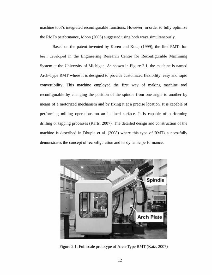
System at the University of Michigan. As shown in Figure 2.1, the machine is named
Arch-Type RMT where it is designed to provide customized flexibility, easy and rapid
convertibility. This machine employed the first way of making machine tool
reconfigurable by changing the position of the spindle from one angle to another by
means of a motorized mechanism and by fixing it at a precise location. It is capable of
performing milling operations on an inclined surface. It is capable of performing
drilling or tapping processes (Karts, 2007). The detailed design and construction of the
machine is described in Dhupia et al. (2008) where this type of RMTs successfully
demonstrates the concept of reconfiguration and its dynamic performance.
Figure 2.1: Full scale prototype of Arch-Type RMT (Katz, 2007)

13
Another RMT prototype is the machine tool named METEOR, an acronym for
(MEhr TEchnologie Orientierte Rekonfigurierbare) that was developed by Abele and
Worn (2009), enables the integration of multiple machining technologies in one
machine workspace. It is shown in Figure 2.2. Based on a platform, METEOR consists
of modules that can be reconfigured by means of construction kit. This machine
employs the both ways of making machine tool reconfigurable as suggested by Moon
(2006) where the modules can be economically adapted through addition, substitution
or structural changes. However, up till today, there are only two machines that have
been developed and both are still under research and development stages. Thus, there
are no reconfigurable machine tools available yet. Over the past few years, a number of
researchers have started to introduce the design principles and methodology in order to
contribute in the development of reliable and functional RMTs. The next section will
further discuss the design methods developed.

14
Figure 2.2: Full scale prototype of METEOR (Abele and Worn, 2009)

15
2.2 Design Principles and Methods of RMTs
Katz and Moon (2000) publish their research work which demonstrates the
principles and methodology to designing a virtual arch type RMTs. This method is
developed to support the invention that has been patented by Koren et al (1997). The
design starts with the analyses on the principles and characteristics (Koren et. al., 1999)
of RMTs that basically serve the modularity, convertability, customization,
intergratibility and diagnosability functions of Reconfigurable Manufacturing System
(RMS). The process continues with the generation of six concepts. Then, the design
steps continued using RMT design software Program for REconfigurable Machine tool
DEsign (PREMADE). This software consists of four modules that represent another
four major steps in design stage which are:
Task clarification,
Structure design,
Supplier selection and,
Module selection.
The task clarification module involves identification of machining information
and machining feature of family data. These data are used to determine the required
motions for machining features. The configuration changes of the machining features
imply reconfigurations of a machine tool which can be achieved either by active motion
or passive motion. The required motions use a screw dual number form which is
developed to represent the motions of tool. The method is explained in details by Moon
and Kota (2002) and Moon (2006). In structural design, graph theory is employed to
show the machine tool’s functional and structural topology.
16
Then in module selection, PREMADE which has the functionality to access the
network and review the available modules information to select all the candidate
modules is used. When the candidate modules are selected, a number of possible
machine configurations are generated to meet the functional and structural requirements
for the set of machining features. In this step, a solution graph is generated. But since
PREMADE software is still under development, the module selection and performance
evaluation is not fully functional yet. Therefore, an existing process selection from other
people’s work was employed.
For performance evaluation, finite element simulation using I-DEAS 6 software
is used. Using Finite Element Method (FEM), static and dynamic characteristic of
virtual arch RMT are determined. During simulation studies, all the interfaces are
assumed to be rigid thus the natural frequencies are estimated higher than its real
values. Publication by Dhupia et al. (2008) validated the performance of the virtual arch
type machine design through its experimental studies. From the experimental results,
the designed machine is found to be satisfactory and comparable to other standard
machine tool alternatives.
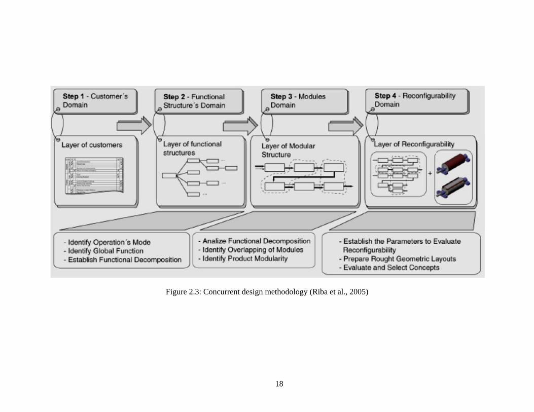
In other research work, Riba et al. (2005) demonstrated a concurrent approach to
design RMTs to process bamboos. The methodology is shown in Figure 2.3. The
method starts with building up a Reference Model. This model is used to identify the
specific issues in the customer’s company such as market opportunities, technological
constraints and declared goals. This information helps to establish the requirement’s
layer which is a simple representation of the machine tools builder intentions on the
reconfigurability function. Then functional structures domain is developed to provide a
17
clear methodological procedure for the definition of the ideal sub-functions for a given
set of requirements. All functions are decomposed to a certain levels with the last layer
represent the sub-function that is more related to the final structure of the machine. The
final structure is selected through decision making process. Once the final structure at
each function is selected, the layer of the modular structure is obtained and finally, the
machine tool with reconfigurable function is produced in the final step.
Extension from Riba’s work, Ahuett et al. (2005) has proposed a directed
evolution modularity framework in designing RMTs. The design methodology proposed
by Riba et al. (2005) has been enhanced by providing machine tool builder’s checklist
as shown in Figure 2.4. In the enhanced methodology, upgradeability and adaptability
are used as important drivers for the RMT. Compared to the proposed method by Katz
and Moon (2000) and Riba et al. (2005), these two factors are additional factors to be
considered. Thus, they provide upgradeability which refers to the ability of the
manufacturer to establish improved technology into the machine.
18
Figure 2.3: Concurrent design methodology (Riba et al., 2005)

19
Figure 2.4: Modular reconfigurability design methodology (Ahuett et al., 2005)
On the other hand, adaptability refers to the capacity of the RMT to suit
customer’s desires. The relevance of this method is to ensure that the machine tool is
manufactured based on customer requirements. Business environment such as financial
condition, competitiveness issues, and labour concern are the influential factors to

20
user’s demand of the machine tool. Ahuett et al. (2005) have discussed the steps
conducted on their case study of metal cutting machine. Four machine versions have
been developed and the performance measures for selection are total cost to produce the
machine, fatigue reduction, increment in productivity, and value added.
Zhang and Zhuming, (2005) employed modular design approach in the
development of reconfigurable parallel kinematic machines. Compared to existing
industrial robots that already in modular configuration, reconfigurable robots introduced
a new dimension to flexible automation in terms of hardware flexibility. It consists of
standard units such as joints and links, which can be efficiently re-configured into the
most suitable arm geometry for its required task. The design approach proposed in their
work was divided into two categories which are (1) identification of possible joints that
suitable for modular architecture of the robots and (2) using Computer Aided Design
(CAD) system for rapid formulation of a suitable configuration through a combination
of these modular joints and links.
From the employment of step (1), there are five variations of reconfigurable
parallel kinematic machines available. In step (2), kinematic analysis model is
developed using forward or inverse model. The use of the model depends on the type of
information acquired. In their research they use actuated joint motions or end-effectors
motion. Later, the developed kinematic model is used to optimize the structural
parameter. Optimization involves maximizing the rotational motion of the end-
effectors. The result from optimization gives a larger workspace without void or empty
space, and it has no interference among the system components.

21
Bi and Wang (2009) introduced an advanced method in optimization of
reconfigurable parallel machining system by proposing a Multidisciplinary Design
Optimization (MDO). The MDO is an approach that includes design analysis in all of
the disciplines including kinematics, dynamics, and control. An integrated toolbox has
been developed to process the analysis. The tool not only provides the information on
workspace manipulability, but also stiffness of the structure, joint forces, tolerances,
optimal structure, graphic simulation and monitoring process.
Katz R. in 2007 published the design principles of reconfigurable machines.
There are five principles which are stressed out. These principles can be used by
machine designer as a checklist to ensure that RMTs requirements are embedded into
the machine. The highlighted principles are divided into two categories (1) necessary
principle and (2) primary principles. The necessary principle is to design a
reconfigurable machine around a specific part family of products, while primary
principles which consist of five criteria, are used to design a better performance of
RMTs (customized flexibility, easy and rapid convertibility, scalability, reconfiguration
at several location, and modularity). The more items integrated in the design of machine
tools, the better the reconfigurability of the machine.
As an example, Arch type RMT has been assessed with the proposed principles.
From the six principles, Arch type fulfilled only three of them which are customized
flexibility, easy and rapid convertibility, and reconfiguration at several locations. From
the findings by Katz (2007), it can be concluded that they still unable to introduce
modularity features to the Arch type RMT to enable spindles exchangeability which is
the case of mating interfaces characteristic between the modules. In order to further
22
understand the interfaces characteristic between assembled modules, next section will
review the performance requirements of modules.
2.3 Functional Requirements of Machine Modules in RMT
The performance of every mechanical interface in mechanical assemblies of the
machine modules determines the level of repeatability, interchangeability, and stability
of the machine, especially in reconfigurable environment. It is strongly influenced the
overall system’s performance in the operating mode where the ability of the assembled
modules to transmit forces and moments is a necessity (Abele et al. 2007). In general,
mechanical assemblies in machine tools are classified into stationary and moving joints.
Stationary joints include the machine base, column, and spindle housing. These
stationary joints usually support the moving joints such as worktables, slides, spindles
and carriages.
In reconfigurable environment, there are special requirements for the mechanical
assembly interfaces compared to existing machine tools such as Dedicated Machine
Tools (DMT) and Flexible Manufacturing System (FMS). Moon (2006) and Abele et al.
(2007) stated that, the fast and accurate interfacing method should be developed for
reconfigurable machine modules. This is to support the ability for the RMT users to
frequently change the modules. Katz (2007) proposed to automate the assembly process
in order to speed it up and keep it precise. To provide shorter assembly time, Abele and
Worn (2009) suggested to specifically designing the geometry of interfaces between
modules to facilitate the functional interactions and simplify the assembly and
disassembly operations as they named the interface as SST-60. SST-60 which employs
23
a plug and play modularity features is designed in order to ease spindle exchangeability.
SST-60 is the design of spindle interfaces for machine tools to serve the requirement for
reconfigurable machine tool named METEOR.
Another important requirement is to maintain the accuracy of the machine tools
each time reconfiguration takes place. The explanation of accuracy is that once the
module is re-assembled, then the geometric accuracy is assured Pasek (2006). This is to
avoid the calibration process that will force the production to stop for setup, aligning
functional axis and re-calibrate the machine. This process is time consuming and costly.
The requirement to assemble the modules accurately was also mentioned by Abele et al.
(2007) and Abele and Worn (2009). They discussed the importance of the mechanical
modules to be aligned precisely in order to reduce positioning error of the tool relative
to the work piece.
The misalignment of assembled modules will give an effect on static and
dynamic components. The static component will produce dimensional deviations on the
work piece while dynamic component will affect its surface quality. Generally,
assembly interfaces are often the weakest chain in the whole mechanical structural
system (Lin and Chen, 2002). This makes the stiffness at the module assembly is lower
compared to its integral part. Therefore, even a small misalignment is not acceptable
which will ruin the accuracy as well stiffness of the machine structure.
Thus, the assembled modules should be able to give the desired stiffness along
its life time (Landers, 2001 and Pasek, 2006). Insufficient stiffness will cause static
deflection and chatter to the machine tool structure. In order to achieve this
requirement, an evaluation method on structural stiffness should be conducted during

24
design stage (Yigit, 2002; Moon, 2006; Lorenzer, 2007; Katz, 2007; Abele et al., 2007,
Wiendahl et al., 2007). Reliability upon the sensitivity of the locking mechanism for
stationary joints to failure during assembly process also requires an assessment (Abele
et al., 2007). This is to certify that the rigidity of the stationary joints is assured. Lin and
Chen (2002) stated that the working performance of the interface between two
assembled modules in stationary joints depends on the form of the mating interface,
surface roughness and the number and distribution of the fixing bolts used in joining the
two modules.
Standardization of machine modules is also an important requirement to allow
interchangeability between different machine builders. Therefore, Moon (2006)
proposed a standard for the machine tool named as ANSI B5.43. However the standard
is for modular machine tool and the standard for reconfigurable machine tool is not yet
available. Abele et al. (2007), Katz (2007), and Abele and Worn (2009) also discussed
the interface standardization where it is believed that it can increase the degree of
interchangeability for the assembly of a maximum variety of module type.
From all the reviews conducted, the summary of the literatures on the functional
requirements of the machine modules in RMTs is tabulated in Table 2.1. Aside from
Abele et al. (2007) and Abele and Worn (2009) that proposed SST-60 design for spindle
module interfaces, there is no other design have been published. The mating interfaces
that applicable to any modules that served the stationary joints in reconfigurable
application is also unavailable. Thus, in the next section, mechanical mating interface
design that is similar to the functional requirements that have been listed in Table 2.1 is
reviewed.

25
Table 2.1: Summary of the functional requirements of the machine modules in RMTs
Num Required function Source of literature
1 Positional accuracy
Abele and Worn (2009) Abele et al. (2007) Moon (2006) Pasek (2006)
2 Quick change by easy for assembly and disassembly
Abele and Worn (2009) Katz (2007) Abele et al. (2007) Moon (2006)
3 Sufficient stiffness between interface
Abele et al. (2007) Lorenzer (2007) Katz (2007) Wiendahl et al. (2007) Pasek (2006) Moon (2006) Lin and Chen (2002) Landers (2001)
4 Standardized interfaces
Abele and Worn (2009) Katz (2007) Moon (2006)
2.4 Relevant Design for Mechanical Mating Interface
As reviewed, the functional requirements of mechanical mating interface are to
have standardized interfaces and able to provide quick change that provides sufficient
stiffness under predetermined accuracy. There are a number of other research fields that
serve those functions. Modular machine tool is one of them. Before RMTs being
introduced, a machine tool is already made in modular form. The machine tool is built
up from many elementary parts to simplify their machining operation (Tsutsumi, 1979).
Research in modular machine tool has already started since 1960’s and the findings can
be used as starting point in the development of RMTs.