DESIGN AND ANALYSIS OF DYNAMIC VOLTAGE RESTORER …ijpres.com/pdf36/3.pdf · design and analysis of...
6
INTERNATIONAL JOURNAL OF PROFESSIONAL ENGINEERING STUDIES Volume 9 /Issue 3 / OCT 2017 IJPRES DESIGN AND ANALYSIS OF DYNAMIC VOLTAGE RESTORER WITH A BATTERY ENERGY STORAGE SYSTEM 1 GORREMUTCHU SRINIVASARAO, 2 B.IMMANUEL RAJ KUMAR 1 M.Tech, NALANDA INSTITUTE OF ENGINEERING &TECHNOLOGY 2 Assistant Professor, NALANDA INSTITUTE OF ENGINEERING &TECHNOLOGY Abstract-In this paper, the control and performance of a DVR are demonstrated with a reduced-rating voltage source converter (VSC). The synchronous reference frame (SRF) theory is used for the control of the DVR. Different voltage injection schemes for dynamic voltage restorers (DVRs) are analyzed. The DVR can regulate the load voltage from the problems such as sag, swell, and harmonics in the supply voltages. Hence, it can protect the critical consumer loads from tripping and consequent losses. A new control technique is proposed to control the capacitor-supported DVR. The control of a DVR is demonstrated with a reduced-rating VSC. The reference load voltage is estimated using the unit vectors. The DVR applications are mainly for sensitive loads that may be drastically affected by fluctuations in system voltage. The synchronous reference frame theory is used for the conversion of voltages from rotating vectors to the stationary frame. The compensation of the voltage sag, swell, and harmonics is demonstrated using a reduced-rating DVR. Index Terms—Dynamic voltage restorer (DVR), power quality, unit vector, voltage harmonics, voltage sag, voltage swell. INTRODUCTION Nowadays, modern industrial devices are mostly based on electronic devices such as programmable logic controllers and electronic drives. The electronic devices are very sensitive to disturbances and become less tolerant to power quality problems such as voltage sags, swells and harmonics. Power quality problems such as transients, sags, swells, and other distortions to the sinusoidal waveform of the supply voltage affect the performance of these equipment pieces. They employ a series of voltage boost technology using solid state switches for compensating voltage sags/swells. The DVR applications are mainly for sensitive loads that may be drastically affected by fluctuations in system voltage. Custom power devices are mainly of three categories such as series-connected compensators known as dynamic voltage restorers (DVRs), shunt- connected compensators such as distribution static compensators, and a combination of series and shunt- connected compensators known as unified power quality conditioner. Voltage sags in an electrical grid are not always possible to avoid because of the finite clearing time of the faults that cause the voltage sags and the propagation of sags from the transmission and distribution systems to the low-voltage loads. DVRs can eliminate most of the sags and minimize the risk of load tripping for very deep sags, but their main drawbacks are their standby losses, the equipment cost, and also the protection scheme required for downstream short circuits. The performance of a DVR with the high-frequency-link transformer. CASE STUDY OF PROPOSED THEORY OPERATION OF DVR The schematic of a DVR-connected system is shown in Fig. 1(a). The voltage Vinj is inserted such that the load voltage Vload is constant in magnitude and is undistorted, although the supply voltage Vs is not constant in magnitude or is distorted. Fig. 1(b) shows the phasor diagram of different voltage Fig. 1. (a) Basic circuit of DVR. (b) Phasor diagram of the DVR voltage injection schemes. During the voltage sag, the voltage is reduced to Vs with a phase lag angle of θ. Now, the DVR injects a voltage such that the load voltage magnitude is maintained at the pre-sag condition. Vinj1 represents the voltage injected in-phase with the supply voltage. With the injection ofVinj2, the load voltage magnitude remains same but it lead Vs
Transcript of DESIGN AND ANALYSIS OF DYNAMIC VOLTAGE RESTORER …ijpres.com/pdf36/3.pdf · design and analysis of...
INTERNATIONAL JOURNAL OF PROFESSIONAL ENGINEERING STUDIES Volume 9 /Issue 3 / OCT 2017
IJPRES
DESIGN AND ANALYSIS OF DYNAMIC VOLTAGE RESTORER WITH A BATTERY ENERGY STORAGE SYSTEM
1GORREMUTCHU SRINIVASARAO, 2B.IMMANUEL RAJ KUMAR 1M.Tech, NALANDA INSTITUTE OF ENGINEERING &TECHNOLOGY
2Assistant Professor, NALANDA INSTITUTE OF ENGINEERING &TECHNOLOGY
Abstract-In this paper, the control and performance of a DVR are demonstrated with a reduced-rating voltage source converter (VSC). The synchronous reference frame (SRF) theory is used for the control of the DVR. Different voltage injection schemes for dynamic voltage restorers (DVRs) are analyzed. The DVR can regulate the load voltage from the problems such as sag, swell, and harmonics in the supply voltages. Hence, it can protect the critical consumer loads from tripping and consequent losses. A new control technique is proposed to control the capacitor-supported DVR. The control of a DVR is demonstrated with a reduced-rating VSC. The reference load voltage is estimated using the unit vectors. The DVR applications are mainly for sensitive loads that may be drastically affected by fluctuations in system voltage. The synchronous reference frame theory is used for the conversion of voltages from rotating vectors to the stationary frame. The compensation of the voltage sag, swell, and harmonics is demonstrated using a reduced-rating DVR.
Index Terms—Dynamic voltage restorer (DVR), power quality, unit vector, voltage harmonics, voltage sag, voltage swell.
INTRODUCTION Nowadays, modern industrial devices are
mostly based on electronic devices such as programmable logic controllers and electronic drives. The electronic devices are very sensitive to disturbances and become less tolerant to power quality problems such as voltage sags, swells and harmonics. Power quality problems such as transients, sags, swells, and other distortions to the sinusoidal waveform of the supply voltage affect the performance of these equipment pieces.
They employ a series of voltage boost technology using solid state switches for compensating voltage sags/swells. The DVR applications are mainly for sensitive loads that may be drastically affected by fluctuations in system voltage. Custom power devices are mainly of three categories such as series-connected compensators known as dynamic voltage restorers (DVRs), shunt-connected compensators such as distribution static compensators, and a combination of series and shunt-connected compensators known as unified power quality conditioner. Voltage sags in an electrical grid are not always possible to avoid because of the finite clearing time of the faults that cause the voltage sags and the propagation of sags from the transmission and distribution systems to the low-voltage loads.
DVRs can eliminate most of the sags and minimize the risk of load tripping for very deep sags, but their main drawbacks are their standby losses, the equipment cost, and also the protection scheme required for downstream short circuits. The performance of a DVR with the high-frequency-link transformer.
CASE STUDY OF PROPOSED THEORY OPERATION OF DVR
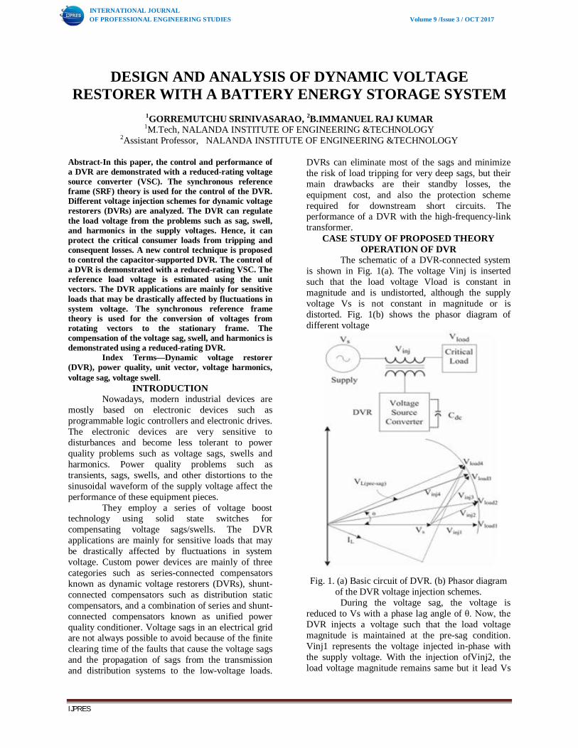
The schematic of a DVR-connected system is shown in Fig. 1(a). The voltage Vinj is inserted such that the load voltage Vload is constant in magnitude and is undistorted, although the supply voltage Vs is not constant in magnitude or is distorted. Fig. 1(b) shows the phasor diagram of different voltage
Fig. 1. (a) Basic circuit of DVR. (b) Phasor diagram
of the DVR voltage injection schemes. During the voltage sag, the voltage is
reduced to Vs with a phase lag angle of θ. Now, the DVR injects a voltage such that the load voltage magnitude is maintained at the pre-sag condition. Vinj1 represents the voltage injected in-phase with the supply voltage. With the injection ofVinj2, the load voltage magnitude remains same but it lead Vs
Gurmeet
Typewritten Text
15
INTERNATIONAL JOURNAL OF PROFESSIONAL ENGINEERING STUDIES Volume 9 /Issue 3 / OCT 2017
IJPRES
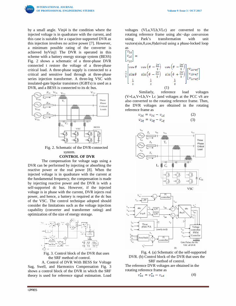
by a small angle. Vinj4 is the condition where the injected voltage is in quadrature with the current, and this case is suitable for a capacitor-supported DVR as this injection involves no active power [7]. However, a minimum possible rating of the converter is achieved byVinj1 The DVR is operated in this scheme with a battery energy storage system (BESS) Fig. 2 shows a schematic of a three-phase DVR connected t restore the voltage of a three-phase critical load. A three-phase supply is connected to a critical and sensitive load through at three-phase series injection transformer. A three-leg VSC with insulated-gate bipolar transistors (IGBTs) is used as a DVR, and a BESS is connected to its dc bus.
Fig. 2. Schematic of the DVR-connected
system. CONTROL OF DVR
The compensation for voltage sags using a DVR can be performed by injecting or absorbing the reactive power or the real power [8]. When the injected voltage is in quadrature with the current at the fundamental frequency, the compensation is made by injecting reactive power and the DVR is with a self-supported dc bus. However, if the injected voltage is in phase with the current, DVR injects real power, and hence, a battery is required at the dc bus of the VSC. The control technique adopted should consider the limitations such as the voltage injection capability (converter and transformer rating) and optimization of the size of energy storage.
Fig. 3. Control block of the DVR that uses
the SRF method of control. A. Control of DVR With BESS for Voltage
Sag, Swell, and Harmonics Compensation Fig. 3 shows a control block of the DVR in which the SRF theory is used for reference signal estimation. Load
voltages (VLa,VLb,VLc) are converted to the rotating reference frame using abc−dqo conversion using Park’s transformation with unit vectors(sin,θ,cos,θ)derived using a phase-locked loop as
(1) Similarly, reference load voltages
(V∗La,V∗Lb,V∗ Lc )and voltages at the PCC vS are also converted to the rotating reference frame. Then, the DVR voltages are obtained in the rotating reference frame as
(2) (3)
Fig. 4. (a) Schematic of the self-supported
DVR. (b) Control block of the DVR that uses the SRF method of control.
The reference DVR voltages are obtained in the rotating reference frame as
(4)
Gurmeet
Typewritten Text
16

INTERNATIONAL JOURNAL OF PROFESSIONAL ENGINEERING STUDIES Volume 9 /Issue 3 / OCT 2017
IJPRES
(5) The error between the reference and actual DVR voltages in the rotating reference frame is regulated using two proportional–integral (PI) controllers. Reference DVR voltages in theabcframe are obtained from a reverse Park’s transformation taking ∗ Ddfrom (4),V ∗ Dq from (5),V ∗ D0 as zero as
(
6) The PWM controller is operated with a switching frequency of 10 kHz. B. Control of Self-Supported DVR for Voltage Sag, Swell, and Harmonics Compensation
Fig. 4(a) shows a schematic of a capacitor-supported DVR connected to three-phase critical loads, and Fig. 4(b) shows a control block of the DVR in which the SRF theory is used for the control of self-supported DVR. Voltages at the PCC vS are converted to the rotating reference frame using abc−dqo conversion using Park’s transformation. The harmonics and the oscillatory components of the voltage are eliminated using low pass filters (LPFs). The components of voltages in the d- and q-axes are
(7) (8)
The compensating strategy for compensation of voltage quality problems considers that the load terminal voltage should be of rated magnitude and undistorted.
Fig. 5. MATLAB-based model of the BESS-
supported DVR-connected system. DVR and the output is considered as a voltage vcap for meeting its losses
(9) Where vde(n) =v dc−vdc(n) is the error between the reference v∗dc and sensed dc voltages vdc at then th sampling instant.Kp1andKi1are the proportional and the integral gains of the dc bus voltage PI controller. The referenced-axis load voltage is therefore expressed as follows:
(10) The amplitude of load terminal voltageVLis controlled to itsreference voltage V ∗ L using another PI controller.
MODELING AND SIMULATION The DVR-connected system consisting of a three-phase supply, three-phase critical loads, and the series injection transformers shown in Fig. 2 is modeled in MATLAB/Simulink environment along with a sim power system toolbox and is shown in Fig. 5. An equivalent load considered is a 10-kVA 0.8-pf lag linear load. The parameters of the considered system for the simulation study are given in the Appendix
Fig. 6. Dynamic performance of DVR with in-phase injection during voltage sag and swell applied to critical load.
The control algorithm for the DVR shown in Fig. 3 is also modeled in MATLAB. The reference DVR voltages are derived from sensed PCC voltages (vsa,vsb,vsc) and load voltages (vLa,vLb,vLc). A PWM controller is used over the reference and sensed DVR voltages to generate the gating signals for the IGBTs of the VSC of the DVR. The capacitor-supported DVR shown in Fig. 4 is also modeled and simulated in MATLAB, and the performances of the systems are compared in three conditions of the DVR.
Gurmeet
Typewritten Text
17
INTERNATIONAL JOURNAL OF PROFESSIONAL ENGINEERING STUDIES Volume 9 /Issue 3 / OCT 2017
IJPRES
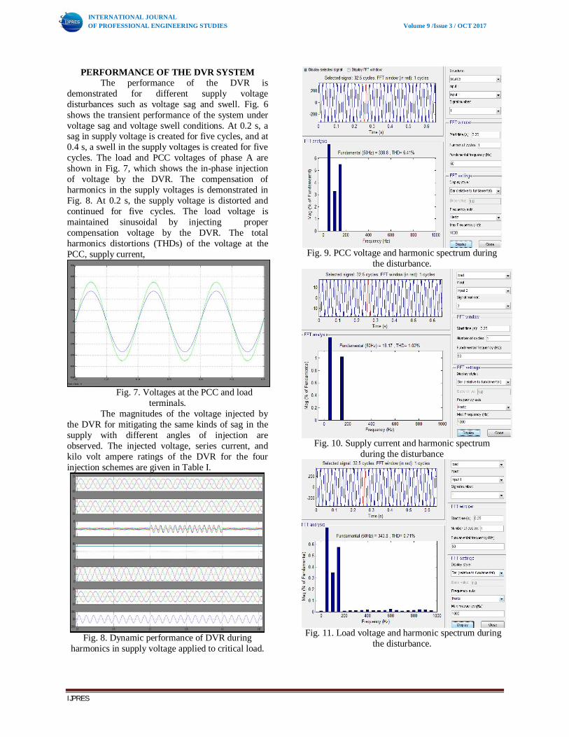
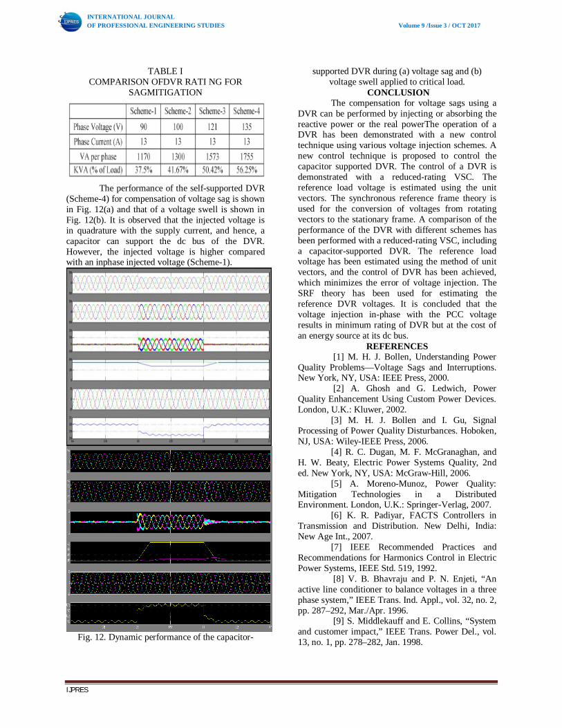
PERFORMANCE OF THE DVR SYSTEM The performance of the DVR is
demonstrated for different supply voltage disturbances such as voltage sag and swell. Fig. 6 shows the transient performance of the system under voltage sag and voltage swell conditions. At 0.2 s, a sag in supply voltage is created for five cycles, and at 0.4 s, a swell in the supply voltages is created for five cycles. The load and PCC voltages of phase A are shown in Fig. 7, which shows the in-phase injection of voltage by the DVR. The compensation of harmonics in the supply voltages is demonstrated in Fig. 8. At 0.2 s, the supply voltage is distorted and continued for five cycles. The load voltage is maintained sinusoidal by injecting proper compensation voltage by the DVR. The total harmonics distortions (THDs) of the voltage at the PCC, supply current,
Fig. 7. Voltages at the PCC and load
terminals. The magnitudes of the voltage injected by
the DVR for mitigating the same kinds of sag in the supply with different angles of injection are observed. The injected voltage, series current, and kilo volt ampere ratings of the DVR for the four injection schemes are given in Table I.
Fig. 8. Dynamic performance of DVR during
harmonics in supply voltage applied to critical load.
Fig. 9. PCC voltage and harmonic spectrum during
the disturbance.
Fig. 10. Supply current and harmonic spectrum
during the disturbance
Fig. 11. Load voltage and harmonic spectrum during the disturbance.
Gurmeet
Typewritten Text
18
INTERNATIONAL JOURNAL OF PROFESSIONAL ENGINEERING STUDIES Volume 9 /Issue 3 / OCT 2017
IJPRES
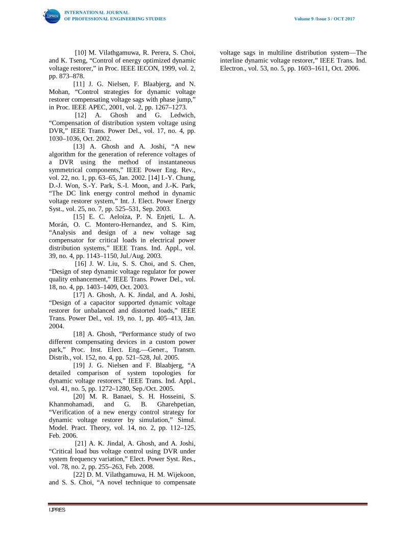
TABLE I COMPARISON OFDVR RATI NG FOR
SAGMITIGATION
The performance of the self-supported DVR
(Scheme-4) for compensation of voltage sag is shown in Fig. 12(a) and that of a voltage swell is shown in Fig. 12(b). It is observed that the injected voltage is in quadrature with the supply current, and hence, a capacitor can support the dc bus of the DVR. However, the injected voltage is higher compared with an inphase injected voltage (Scheme-1).
Fig. 12. Dynamic performance of the capacitor-
supported DVR during (a) voltage sag and (b) voltage swell applied to critical load.
CONCLUSION The compensation for voltage sags using a
DVR can be performed by injecting or absorbing the reactive power or the real powerThe operation of a DVR has been demonstrated with a new control technique using various voltage injection schemes. A new control technique is proposed to control the capacitor supported DVR. The control of a DVR is demonstrated with a reduced-rating VSC. The reference load voltage is estimated using the unit vectors. The synchronous reference frame theory is used for the conversion of voltages from rotating vectors to the stationary frame. A comparison of the performance of the DVR with different schemes has been performed with a reduced-rating VSC, including a capacitor-supported DVR. The reference load voltage has been estimated using the method of unit vectors, and the control of DVR has been achieved, which minimizes the error of voltage injection. The SRF theory has been used for estimating the reference DVR voltages. It is concluded that the voltage injection in-phase with the PCC voltage results in minimum rating of DVR but at the cost of an energy source at its dc bus.
REFERENCES [1] M. H. J. Bollen, Understanding Power
Quality Problems—Voltage Sags and Interruptions. New York, NY, USA: IEEE Press, 2000.
[2] A. Ghosh and G. Ledwich, Power Quality Enhancement Using Custom Power Devices. London, U.K.: Kluwer, 2002.
[3] M. H. J. Bollen and I. Gu, Signal Processing of Power Quality Disturbances. Hoboken, NJ, USA: Wiley-IEEE Press, 2006.
[4] R. C. Dugan, M. F. McGranaghan, and H. W. Beaty, Electric Power Systems Quality, 2nd ed. New York, NY, USA: McGraw-Hill, 2006.
[5] A. Moreno-Munoz, Power Quality: Mitigation Technologies in a Distributed Environment. London, U.K.: Springer-Verlag, 2007.
[6] K. R. Padiyar, FACTS Controllers in Transmission and Distribution. New Delhi, India: New Age Int., 2007.
[7] IEEE Recommended Practices and Recommendations for Harmonics Control in Electric Power Systems, IEEE Std. 519, 1992.
[8] V. B. Bhavraju and P. N. Enjeti, “An active line conditioner to balance voltages in a three phase system,” IEEE Trans. Ind. Appl., vol. 32, no. 2, pp. 287–292, Mar./Apr. 1996.
[9] S. Middlekauff and E. Collins, “System and customer impact,” IEEE Trans. Power Del., vol. 13, no. 1, pp. 278–282, Jan. 1998.
Gurmeet
Typewritten Text
19
INTERNATIONAL JOURNAL OF PROFESSIONAL ENGINEERING STUDIES Volume 9 /Issue 3 / OCT 2017
IJPRES
[10] M. Vilathgamuwa, R. Perera, S. Choi, and K. Tseng, “Control of energy optimized dynamic voltage restorer,” in Proc. IEEE IECON, 1999, vol. 2, pp. 873–878.
[11] J. G. Nielsen, F. Blaabjerg, and N. Mohan, “Control strategies for dynamic voltage restorer compensating voltage sags with phase jump,” in Proc. IEEE APEC, 2001, vol. 2, pp. 1267–1273.
[12] A. Ghosh and G. Ledwich, “Compensation of distribution system voltage using DVR,” IEEE Trans. Power Del., vol. 17, no. 4, pp. 1030–1036, Oct. 2002.
[13] A. Ghosh and A. Joshi, “A new algorithm for the generation of reference voltages of a DVR using the method of instantaneous symmetrical components,” IEEE Power Eng. Rev., vol. 22, no. 1, pp. 63–65, Jan. 2002. [14] I.-Y. Chung, D.-J. Won, S.-Y. Park, S.-I. Moon, and J.-K. Park, “The DC link energy control method in dynamic voltage restorer system,” Int. J. Elect. Power Energy Syst., vol. 25, no. 7, pp. 525–531, Sep. 2003.
[15] E. C. Aeloíza, P. N. Enjeti, L. A. Morán, O. C. Montero-Hernandez, and S. Kim, “Analysis and design of a new voltage sag compensator for critical loads in electrical power distribution systems,” IEEE Trans. Ind. Appl., vol. 39, no. 4, pp. 1143–1150, Jul./Aug. 2003.
[16] J. W. Liu, S. S. Choi, and S. Chen, “Design of step dynamic voltage regulator for power quality enhancement,” IEEE Trans. Power Del., vol. 18, no. 4, pp. 1403–1409, Oct. 2003.
[17] A. Ghosh, A. K. Jindal, and A. Joshi, “Design of a capacitor supported dynamic voltage restorer for unbalanced and distorted loads,” IEEE Trans. Power Del., vol. 19, no. 1, pp. 405–413, Jan. 2004.
[18] A. Ghosh, “Performance study of two different compensating devices in a custom power park,” Proc. Inst. Elect. Eng.—Gener., Transm. Distrib., vol. 152, no. 4, pp. 521–528, Jul. 2005.
[19] J. G. Nielsen and F. Blaabjerg, “A detailed comparison of system topologies for dynamic voltage restorers,” IEEE Trans. Ind. Appl., vol. 41, no. 5, pp. 1272–1280, Sep./Oct. 2005.
[20] M. R. Banaei, S. H. Hosseini, S. Khanmohamadi, and G. B. Gharehpetian, “Verification of a new energy control strategy for dynamic voltage restorer by simulation,” Simul. Model. Pract. Theory, vol. 14, no. 2, pp. 112–125, Feb. 2006.
[21] A. K. Jindal, A. Ghosh, and A. Joshi, “Critical load bus voltage control using DVR under system frequency variation,” Elect. Power Syst. Res., vol. 78, no. 2, pp. 255–263, Feb. 2008.
[22] D. M. Vilathgamuwa, H. M. Wijekoon, and S. S. Choi, “A novel technique to compensate
voltage sags in multiline distribution system—The interline dynamic voltage restorer,” IEEE Trans. Ind. Electron., vol. 53, no. 5, pp. 1603–1611, Oct. 2006.
Gurmeet
Typewritten Text
20