Design and Analysis of a Novel MEMS Piezoresistive ...
21
Design and Analysis of a Novel MEMS Piezoresistive Pressure Sensor with Annular Groove Membrane and Centre Mass for Low Pressure Measurements ROHAN SAHAY VIT University JAGRITI HIRWANI VIT University Sumit Kumar Jindal ( [email protected] ) VIT University SREEKANTH P K VIT University AJAY KUMAR National Institute of Technology Jamshedpur Research Article Keywords: Silicon Diaphragm, Annular groove, Centre mass, Square membrane, MEMS piezoresistive sensor Posted Date: May 7th, 2021 DOI: https://doi.org/10.21203/rs.3.rs-430347/v1 License: This work is licensed under a Creative Commons Attribution 4.0 International License. Read Full License
Transcript of Design and Analysis of a Novel MEMS Piezoresistive ...

Design and Analysis of a Novel MEMSPiezoresistive Pressure Sensor with Annular GrooveMembrane and Centre Mass for Low PressureMeasurementsROHAN SAHAY
VIT UniversityJAGRITI HIRWANI
VIT UniversitySumit Kumar Jindal ( [email protected] )
VIT UniversitySREEKANTH P K
VIT UniversityAJAY KUMAR
National Institute of Technology Jamshedpur
Research Article
Keywords: Silicon Diaphragm, Annular groove, Centre mass, Square membrane, MEMS piezoresistivesensor
Posted Date: May 7th, 2021
DOI: https://doi.org/10.21203/rs.3.rs-430347/v1
License: This work is licensed under a Creative Commons Attribution 4.0 International License. Read Full License

1
TITLE PAGE
CONCISE AND INFORMATIVE TITLE
Design and analysis of a novel MEMS piezoresistive pressure sensor with annular groove membrane
and centre mass for low pressure measurements
AUTHORS
1Rohan Sahay 2Jagriti Hirwani 3*Sumit Kumar Jindal 4Sreekanth P K 5Ajay Kumar
AFFILIATION AND ADDRESS OF THE AUTHORS
1,2,3,4 School of Electronics Engineering, Vellore Institute of Technology, Vellore, Tamil Nadu, India.
5 Department of Electronics and Communication Engineering, National Institute of Technology,
Jamshedpur, Jharkhand, India.
CORRESPONDING AUTHOR
*Email: [email protected], Ph. No: +91-8603559888

2
Design and analysis of a novel MEMS piezoresistive pressure sensor with annular groove membrane
and centre mass for low pressure measurements
Structured Abstract
Purpose: Micro Electronic Mechanical System (MEMS) based pressure sensors have found their use in
multiple applications lately in the field of healthcare, automotive etc. These sensors however face a trade-
off between sensitivity and linearity which limits sensor performance. The proposed design aims to achieve
an enhanced sensor performance by alleviating the sensitivity and linearity trade-off.
Methods: Novel structures such as annular grooves and center mass have been introduced for providing
better sensor performance along with membrane dimension optimization. Annular grooves generate Stress
Concentrated Regions (SCRs) on membrane surface on application of external pressure which enhances
sensor sensitivity while center mass provides partial stiffening of the membrane and hence reduces non-
linearity.
Results: The proposed sensor achieves a low non-linearity error of 0.15% FSS with a well-balanced
sensitivity of 28.0 mV/V/psi.
Conclusion: The proposed novel sensor structure achieves a relatively better performance in comparison to
conventional membrane variants. With a high sensitivity and appreciable linearity, the novel structure proves
to be ideal for low pressure measurements in the range (0-5)KPa.
Keywords: Silicon Diaphragm, Annular groove, Centre mass, Square membrane, MEMS piezoresistive
sensor
Declarations:
Funding- Not Applicable.
Conflicts of interest/Competing interests –Not Applicable.
Availability of data and material- Not Applicable.
Code availability- Licensed Version of MATLAB & COMSOL has been used to generate plots.
Authors' contributions- Optional (Not Applicable).
I. INTRODUCTION
Micro electromechanical system (MEMS) based piezoresistive pressure sensors find wide scale use because
of their small size, relatively low cost, simple fabrication and Direct Current (DC) output. Micro
electromechanical piezoresistive pressure sensors have found their use in automobile, aerospace and
petrochemical industry etc for pressure measurements. The basic principle behind this sensor is based on a
slender membrane which shows deflection when a pressure is exerted externally on the surface of the
membrane. This deflection is measured using a Wheatstone bridge which gives a proportionate voltage
output[1].
There is a trade-off between linearity and sensitivity, especially for low pressure measurements in
piezoresistive pressure sensor [2][3] and hence the design and fabrication of these piezoresistive pressure
sensors require acute balancing between the two. The membrane sensitivity varies in proportion to the ratio
of membrane length a and membrane thickness h, which can be improved by adjusting the membrane
dimensions [3]. However, the nonlinearity error of the membrane increases with this ratio at a much faster
3
rate, because of the fact that error in nonlinearity of the pressure-to-stress conversion is proportional to 4
a
h
[4]. This effect has been described as the “balloon effect” [5]. Many previous works have been performed
aiming to assuage the contradiction between sensitivity and non-linearity. Most of these works are
centered around the use of stress concentration regions (SCRs) for sensitivity enhancement while some
concentrate on the use of membrane stiffening/modification techniques in order to reduce deflection and
hence non-linearity. The SCRs allow utilization of higher strain energies by the piezoresistors, when these
resistors are placed on the SCRs thereby improving the sensitivity. A cross beam structure on a membrane
in order to produce SCRs was proposed for low pressure measurements [6]. Similarly an accelerometer
with a beam-mass membrane which obtained a considerable sensitivity was simulated [7]. A beam-
membrane-dual-island structure was proposed based on the concept of SCR which proved defective in
producing high sensitivity level (17.339 μV/V/Pa)[8].
The membrane deflection increases the slope of the output curve, adding to the variation between the actual
output and the ideal linear output [9]. This leads to a large ascend in the pressure nonlinearity error (PNL).
In order to minimize this deflection, stiffening of the membrane is done using various methods. A sensor
with a thin-walled hollow stiffening structure was developed on a thin silicon diaphragm, obtained a non-
linearity of less than 0.40% FS (Full Scale) [10]. A bossed membrane piezoresistive pressure sensor was
designed with its nonlinearity error reaching as low as 0.14% FSS for applications involving low pressure
[11]. Similarly a novel diaphragm installed with a boss and peninsula-island structure used for membrane
stiffening was proposed [12] and it obtained a low nonlinearity error for its operating range. It is fair
enough to deduce that producing SCRs and reducing deflection are the two main aspects of obtaining good
sensor characteristics i.e. high sensitivity along with low nonlinearity error.
This work proposes a novel structure with annular grooves on a membrane. The membrane is stiffened
using a square-shaped center mass in order to envisage the electromechanical response of a piezoresistive
pressure sensor for pressure range of (0-5)KPa. The proposed structure is modeled and analyzed using
finite element method(FEM) analysis with the help of COMSOL Multiphysics software. An estimation of
the stress distribution and analysis of the deflection of proposed structure is made. In comparison to the
existing literature an attempt has been made to alleviate the trade-off between sensitivity and linearity and
realize a micro size sensor for low pressure measurement with considerably high accuracy.
II. DESIGN AND PRINCIPLES
High stress and linear output are the two factors which characterize sensor performance. While large
membranes provide high sensitivity, they lack adequate linearity. The vice versa is true for membranes
smaller in size. The proposed sensor design uses a square membrane rather than a rectangular or circular
because of its higher stress generation [13]. The elasticity theory illustrates the maximum stress for the
square membrane[17] as
2
20.308 (1 )SM
L
H
(1)
Here, H is the membrane thickness; μ refers to the Poisson ratio, L is the length of sides of the square
membrane. The maximum stress developed in a square membrane is 15% more than that of a rectangular
membrane and 60% more than the circular one [16].

4
\Oversized membrane deflection is one of the critical causes of non-linearity between pressure and
deformation of the membrane. The dependence of deflection on the pressure applied remains linear as long
as the small deflection theory is satisfied. When the deflection exceeds a definite fraction of the membrane
thickness, the large deflection theories work, leading to the nonlinearity between pressure and deflection as
discussed. In order to maintain linearity, the deflection ( maxw ) should be lesser than 1/5 of the membrane
thickness[15] where:
4 2
max 3
0.0152 (1 )PL vw
EH
(2)
Here P is the pressure applied, E is the Young’s modulus and H refers to thickness of the membrane.
Reduced membrane deflection helps to establish low nonlinearity along with high stability. The proposed
structure hence aims to minimize deflection through a novel structure that has been discussed in the
subsequent section.
III. STRUCTURE DESIGN
The design is characterised by an annularly grooved membrane supported via a square central mass as
shown in Fig1a and Fig 1b. Square diaphragm are easy and cost effective to fabricate for pressure sensors
using anisotropic wet etchants as they have better sensitivity and produce relatively higher stress[20]. The
substrate used for the sensor chip is N-type silicon wafer due to its unique mechanical properties [15]. Four
grooves are present with ribs between each of them on the membrane’s front side. Annular grooves
promote the formation of High Concentrated Stress Profile (HCSP) which increases the membrane
sensitivity. The dimensions of the groove are 60µm in width and 10µm in depth while the membrane
dimensions are 3600µm in length and 30µm in thickness.
(a)
(b)
Fig.1 Structure of proposed membrane: (a) Front view (b) Rare view

5
The centre mass in the proposed design accounts for the stability of the membrane and reduces the non-
linearity error between pressure and membrane deflection. Based on the small deformation theory, the
central mass pattern contributes to the stiffness change and decreases the pressure nonlinearity to smaller
than 1.0% FSS[19].The performance of the sensor is affected by the thickness of the central mass.
According to the simulation results, membrane sensitivity does not vary much on increasing the thickness
of centre mass beyond 50µm[14].Hence the thickness of the square centre mass has been chosen as 50µm.
and the side length as 1200µm.
(a)
(b)
Fig.2 Conventional membranes: (a) C-type membrane (b) E-type membrane
IV. GEOMETRY ANALYSIS
The deflection and sensitivity of the membrane is determined by its geometry. The proposed geometry has
been analysed with respect to the conventional C and E type membranes in terms of both deflection and
sensitivity as parameters. A conventional flat square membrane is referred to as a C-type membrane as
shown in Fig.2a. On the other hand an E-type membrane consists of a membrane with a centre mass as
shown in Fig.2b. Finite element method (FEM) analysis was performed for the conventional C and E type
membranes as well as for the proposed membrane. The membrane dimensions for the conventional
membranes considered for comparison with proposed structure has been chosen as 3600µm, same as that of
the latter. N-type silicon has been used as material for the conventional membranes as well as the proposed
membrane. The applied pressure was gradually increased from 0KPa to 5KPa. The deflection and stress
plots are obtained through FEM analysis using COMSOL Multiphysics software. It has been used for
comparing linearity and sensitivity of the proposed membrane with that of the conventional membranes.
The output sensitivity depends directly on the stress generated on the membrane surface. For a
conventional C-type square membrane, the stress distribution at the SCRs and the central deflection are
given as Eq.(1) and Eq.(2) respectively.
The stress distribution for a C-type membrane has been shown in Fig.3a. As it is evident, maximum stress
is observed at the middle of the pedestal sides. While the C type produces considerable stress, its
membrane stability remains a critical issue leading to large deflection.

6
The issue of deflection in the case of C type as seen in Fig.3b is addressed using an E-type membrane
which introduces a centre mass. The centre mass locally stiffens the membane and reduces deflection
considerably. The central deflection E and the stress E at the SCRs for the E-type membrane are given
as Eq.(3) and Eq.(4) respectively[14]
4 242
30.0152 (1 ) 1 4 lnE
PL l l lv
EH L L L
(3)
2 2
20.308 (1 ) 1E
L lP v
H L
(4)
Here l is the length of central mass, P is the applied pressure, L refers to the side length of the square
membrane while H denotes the membrane thickness. E and ʋ refers to Young’s modulus and Poisson’s
ratio respectively. The stress and the deflection for the E-type membrane varies with distance from the
membrane centre and is shown in Fig.3c and Fig.3d respectively.
(a)
(b)
7
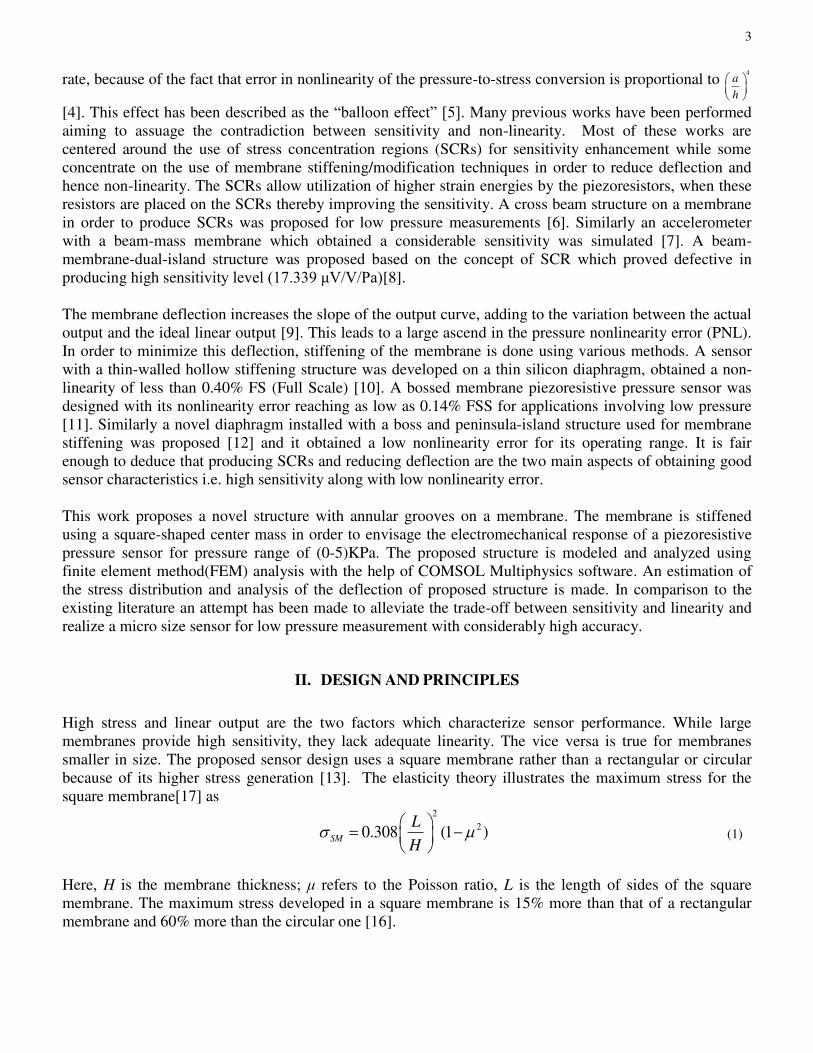
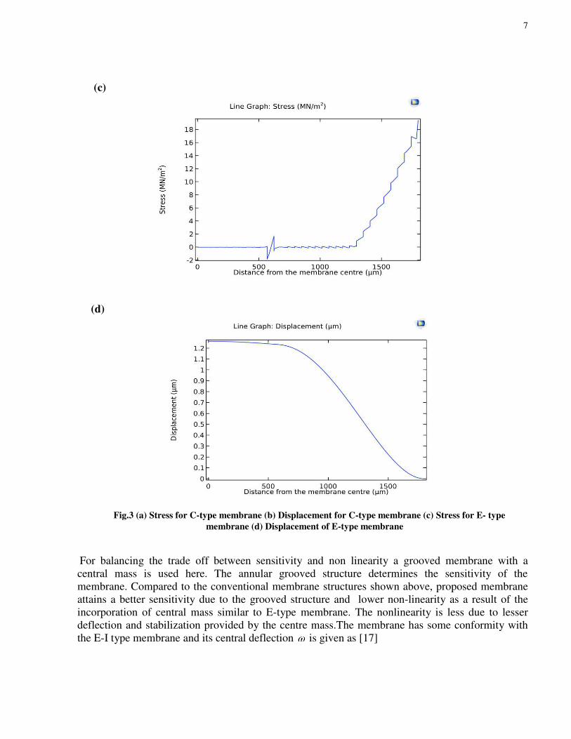
(c)
(d)
Fig.3 (a) Stress for C-type membrane (b) Displacement for C-type membrane (c) Stress for E- type
membrane (d) Displacement of E-type membrane
Fi2Stress for C-t
For balancing the trade off between sensitivity and non linearity a grooved membrane with a
central mass is used here. The annular grooved structure determines the sensitivity of the
membrane. Compared to the conventional membrane structures shown above, proposed membrane
attains a better sensitivity due to the grooved structure and lower non-linearity as a result of the
incorporation of central mass similar to E-type membrane. The nonlinearity is less due to lesser
deflection and stabilization provided by the centre mass.The membrane has some conformity with
the E-I type membrane and its central deflection is given as [17]
8
2 3 23
3 2 2
3[1 ( / ) ]
8 (1 ) 4(1 )
L b g HP
bg E g
(5)
Where
2 ( 2 )gbE g LE bE
LbD
(6)
and
3
212(1 )
EHD
(7)
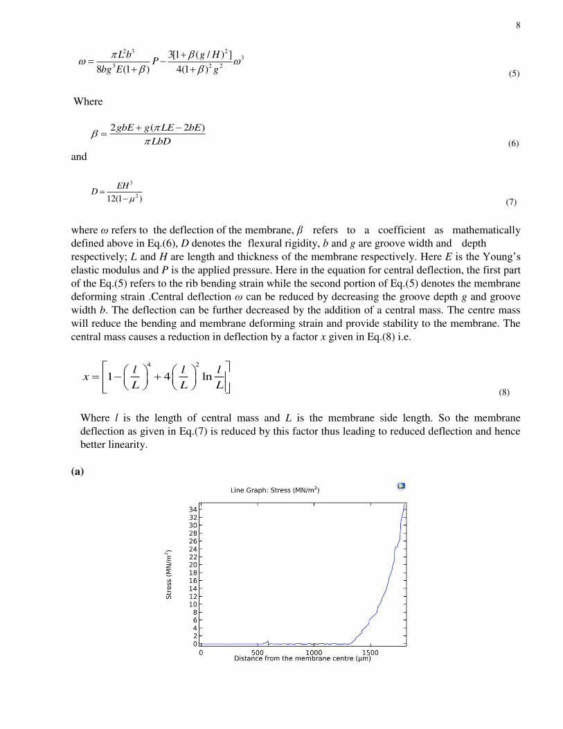
where ω refers to the deflection of the membrane, β refers to a coefficient as mathematically
defined above in Eq.(6), D denotes the flexural rigidity, b and g are groove width and depth
respectively; L and H are length and thickness of the membrane respectively. Here E is the Young’s elastic modulus and P is the applied pressure. Here in the equation for central deflection, the first part
of the Eq.(5) refers to the rib bending strain while the second portion of Eq.(5) denotes the membrane
deforming strain .Central deflection ω can be reduced by decreasing the groove depth g and groove
width b. The deflection can be further decreased by the addition of a central mass. The centre mass
will reduce the bending and membrane deforming strain and provide stability to the membrane. The
central mass causes a reduction in deflection by a factor x given in Eq.(8) i.e.
4 2
1 4 lnl l l
xL L L
(8)
Where l is the length of central mass and L is the membrane side length. So the membrane
deflection as given in Eq.(7) is reduced by this factor thus leading to reduced deflection and hence
better linearity.
(a)

9
(b)
(c)
(d)
Fig.4 (a) Stress for proposed membrane (b) Displacement for proposed membrane (c) Output vs. applied
pressure of proposed membrane (d) Non linearity vs. applied pressure for proposed membrane

10
The stress distribution for the proposed membrane is shown in Fig.4a. The membrane proposed in this
work achieves 76.01% higher stress generation than E-type and 47.73% than C-type membrane. Moreover,
the novel structure attains deflection as shown in Fig.4b which is 38.4% smaller than the conventional C-
type membrane and approximately 11.11% smaller deflection than a conventional E-type membrane. The
stress values obtained from COMSOL at different applied pressure were used to calculate the proposed
sensor output and non-linearity. The output and non-linearity values with respect to varying applied
pressure were used to obtain Fig.4c and Fig.4d respectively using MATLAB. The sensitivity of the
membrane can be interpreted from the slope of the output vs. pressure plot as shown in Fig.4c. The
proposed membrane achieves appreciable sensitivity with minimal non-linearity as depicted in Fig.4d.
In this work, COMSOL Multiphysics software has been used to analyse the performance of the membrane
through FEM analysis. The membrane dimensions for the study have been defined as (3600 x 3600) μm and a thickness of 30μm is taken. Piezoresistive property is found in several materials like Silicon,
Polysilicon and SiC. Silicon is well suited here because of its small size, less weight and small power
constraints. It also has a wide variety of CMOS compatible process options. The material used for the
proposed structure is N-type Silicon[18] having properties as shown in Table1.
Table1. Properties for N-type silicon
Properties Values Properties Values
Density (kg/m3) 2330 Yield strength
(GPa)
7
Band gap(eV) 1.1 Hardness (kg/mm2) 1000
Poisson ratio 0.28 Young elastic modulus
(GPa)
169
V. FEM ANALYSIS
The boundary conditions are applied on the interface between chip and the glass. The number of elements
in the finite element model (FEM) is 26738. The pressure applied is set at 5KPa. The Von-Mises stress
distribution for the analysed structure has been depicted in Fig.5a.
(a)

11
(b)
Fig.5 (a) Von-Misses stress (b) Surface Stress distribution for proposed membrane
The Fig.5b illustrates concentration of stress around the rib. The stress concentrated regions occur at the rib
surface indicated by the reddish yellow around the hinge and are called HCSP. The output of the sensor
varies in proportion with the differential stress at the piezoresistor area and is given in Eq.(9)[17]
44 44
1 1( )
2 2out l t in R inU U U
(9)
Here Π44 denotes the shear piezoresistive coefficient, σ t refers to the transversal stress and σl is the
longitudinal stress, Uout refers to the output voltage while Uin denotes the input voltage. It is evident that
the output voltage depends on σR i.e. differential stress. For attaining maximum sensitivity, piezoresistors
must be placed at the HCSP regions.
The stress are mainly concentrated within a small range (±100 μm), which means the strain energy is strictly restricted in a narrow area on the surface of the rib region and the
energy does not spread outside the HCSP [17]. The maximum strain energy is used by the four
piezoresistors when the longitudinal piezoresistors are placed along x direction lengthwise while the
transversal ones are located in the y-direction breadthwise. The deflection of the membrane varies with the
distance from the membrane centre. It is observed that maximum deflection occurs at the membrane centre
while it is negligible at the fixed membrane boundaries/edges.
12
(a)
(b)
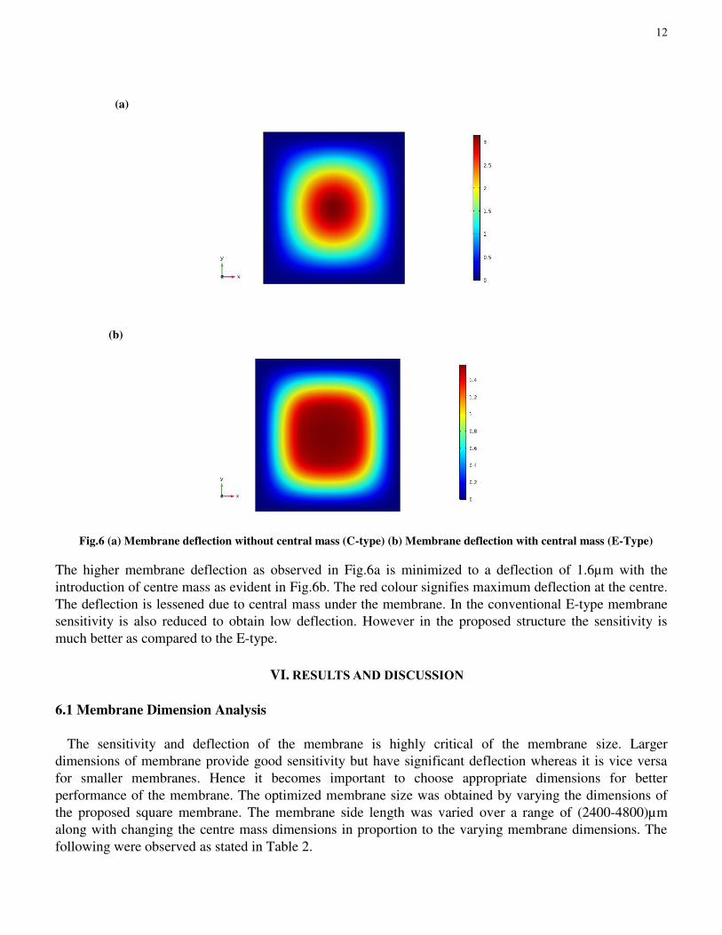
Fig.6 (a) Membrane deflection without central mass (C-type) (b) Membrane deflection with central mass (E-Type)
The higher membrane deflection as observed in Fig.6a is minimized to a deflection of 1.6µm with the
introduction of centre mass as evident in Fig.6b. The red colour signifies maximum deflection at the centre.
The deflection is lessened due to central mass under the membrane. In the conventional E-type membrane
sensitivity is also reduced to obtain low deflection. However in the proposed structure the sensitivity is
much better as compared to the E-type.
VI. RESULTS AND DISCUSSION
6.1 Membrane Dimension Analysis
The sensitivity and deflection of the membrane is highly critical of the membrane size. Larger
dimensions of membrane provide good sensitivity but have significant deflection whereas it is vice versa
for smaller membranes. Hence it becomes important to choose appropriate dimensions for better
performance of the membrane. The optimized membrane size was obtained by varying the dimensions of
the proposed square membrane. The membrane side length was varied over a range of (2400-4800)µm
along with changing the centre mass dimensions in proportion to the varying membrane dimensions. The
following were observed as stated in Table 2.

13
Table 2. Comparison between various membrane sizes
Membrane side
length (µm)
Stress (KPa) Deflection(µm)
2400 16 0.32
3600 34 1.6
4800 65 5
Through the results it was perceived that the membrane was able to attain an appropriate balance between
sensitivity and deflection for the membrane dimension of (3600 x 3600)µm. The deflection was observed to
be 1.6µm while the maximum stress incurred was 34µm over a pressure range of (0-5)KPa. Consequently,
an appreciable sensitivity of 28mv/KPa was observed for the proposed membrane dimension.
The thickness of the membrane impacts its sensitivity. As the membrane thickness increases, the Von
Mises stress produced decreases so it is better to keep a lesser membrane thickness. However a very thin
membrane will destabilize it and lead to a high non linearity error. So the optimum value chosen for the
membrane thickness is 30µm.
After analysing different dimensions for the membrane, it was inferred from the simulation results that at
the proposed dimensions, the membrane tends to attain a satisfactory equilibrium between sensitivity and
deflection.
6.2 Centre Mass Dimensions
The centre mass thickness is chosen to be 50µm because there is only (0.4- 0.5)% decrease in non-linearity
error when the thickness is increased from 50µm to 70µm. When the thickness of the central mass is
analysed at less than 50µm, in this case with a 20µm thickness, the maximum stress obtained is 55MPa but
a higher deflection of 2.8µm is obtained thereby increasing the non-linearity.
The side length of the central mass was varied from (700-1400)µm. It was found that with an increase in
length not only the deflection decreases but also the maximum stress produced decreases. At 1400µm side
length, the maximum stress produced was less than that of chosen 1200µm side length while the
nonlinearity reduction was considerably less. When side length lesser than 1200µm was simulated, higher
deflection was observed with slight increase in maximum stress generated. Hence 1200µm side length was
found to be appropriate in terms of both better sensitivity and low non-linearity.
VII. CONCLUSION
This work analyses and evaluates a theoretical model of a square piezoresistive membrane with a centre
mass and grooved structure. The proposed membrane was examined with respect to the standard membrane
variants i.e. E and C type. The FEM analysis for the former was performed and the outcome of the
simulations provided a fair balance between stress corresponding to the sensitivity and deflection of the
membrane which corresponds to non-linearity. The central mass stiffens the membrane and the annular

14
grooved structure provides enhanced sensitivity for the membrane. The prospective membrane brought
about an improved performance along the lines of sensitivity and linearization with respect to the compared
membrane types.
AUTHOR DECLARATIONS SECTION
* Ethics approval and consent to participate: Not Applicable
* Consent for publication: Yes
* Availability of data and materials: Not Applicable
* Competing interests: Not Applicable
* Funding: Not Applicable
* Authors' contributions: All authors contributed to the study conception and design. Material
preparation, simulation and analysis were performed by all the authors together. The first draft of the
manuscript was written by Mr. Rohan Sahay and all authors commented on previous versions of the
manuscript. All authors read and approved the final manuscript.
* Acknowledgements: Not Applicable
Compliance with Ethical Standards section
* Disclosure potential conflicts of interest: Not Applicable
* Research involving Human Participants and/or Animals: Not Applicable
* Informed consent: Not Applicable
REFERENCES
[1] Kumar, S.S. and Pant, B.D. “Polysilicon thin film piezoresistive pressure microsensor: design, fabrication and
characterization” Microsystem Technologies, 21(9), pp.1949-1958. (2015)
[2] Yu, H. and Huang, J, ”Design and application of a high sensitivity piezoresistive pressure sensor for low pressure
conditions”. Sensors, 15(9), pp.22692-22704 (2015)
[3] Kumar, S.S. and Pant, B.D, “Effect of piezoresistor configuration on output characteristics of piezoresistive pressure
sensor: an experimental study”. Microsystem technologies, 22(4), pp.709-719. (2016)
[4] Kumar, S.S. and Pant, B.D, “Design principles and considerations for the ‘ideal’silicon piezoresistive pressure sensor: a
focused review”. Microsystem technologies, 20(7), pp.1213-1247. (2014)
[5] Marco, S., Samitier, J., Ruiz, O., Morante, J.R. and Esteve, J, “High-performance piezoresistive pressure sensors for
biomedical applications using very thin structured membranes”. Measurement science and technology, 7(9), pp.1195-
1203. (1996)
[6] Tian, B., Zhao, Y., Jiang, Z. and Hu, B., “The design and analysis of beam-membrane structure sensors for micro-
pressure measurement”. Review of Scientific Instruments, 83(4), pp.045003-1-045003-8. (2012)
[7] Sharma, A., Mukhiya, R., Kumar, S.S. and Pant, B.D.,” Design and simulation of bulk micro machined accelerometer for
avionics application”. In VLSI Design and Test (pp. 94-99). Springer, Berlin, Heidelberg. (2013)
[8] Meng, X. and Zhao, Y., “The design and optimization of a highly sensitive and overload-resistant piezoresistive pressure
sensor”. Sensors, 16(3), pp.348-359. (2016)

15
[9] Chiou, J.A. and Chen, S., “Pressure nonlinearity of micro machined piezoresistive pressure sensors with thin diaphragms
under high residual stresses”. Sensors and Actuators A: Physical, 147(1), pp.332-339. (2008)
[10] Kinnell, P.K., King, J., Lester, M. and Craddock, R., “A hollow stiffening structure for low-pressure sensors”. Sensors
and Actuators A: Physical, 160(1-2), pp.35-41. (2010)
[11] Nambisan, R., Kumar, S.S. and Pant, B.D., “Sensitivity and non-linearity study and performance enhancement in bossed
diaphragm piezoresistive pressure sensor”. In 2015 19th International Symposium on VLSI Design and Test (VDAT) (pp.
1-6). IEEE. (2015)
[12] Xu, T., Zhao, L., Jiang, Z., Guo, X., Ding, J., Xiang, W. and Zhao, Y., “A high sensitive pressure sensor with the novel
bossed diaphragm combined with peninsula-island structure”. Sensors and Actuators A: Physical, 244, pp.66-76. (2016)
[13] Hsu, T.R., MEMS and microsystems: design, manufacture, and nanoscale engineering. John Wiley & Sons. (2008)
[14] Li, C., Cordovilla, F., Jagdheesh, R. and Ocaña, J.L., “Design and optimization of a novel structural MEMS
piezoresistive pressure sensor”. Microsystem Technologies, 23(10), pp.4531-4541. (2017)
[15] Timoshenko S, Woinowsky-Krieger S ,Theory of plates and shells. McGraw-Hill Kogakusha, Tokyo (1959)
[16] Yasukawa, A., Shimazoe M. and Matsuoka, Y., “Simulation of circular silicon pressure sensors with a center boss for
very low pressure measurement”. IEEE Transactions on Electron Devices, 36(7), pp.1295-1302. (1989)
[17] Li, C., Cordovilla, F. and Ocaña, J.L., “The design and analysis of a novel structural piezoresistive pressure sensor for
low pressure measurement”. Microsystem Technologies, 23(12), pp.5677-5687. (2017)
[18] Nisanth, A., Suja, K.J. and Komaragiri, R. , “Performance analysis of a silicon piezoresistive pressure sensor based on
diaphragm geometry and piezoresistor dimensions”. In Circuit, Power and Computing Technologies (ICCPCT), 2014
International Conference on (pp. 1273-1278). IEEE. (2014)
[19] Li, C. and Ocaña, J.L., “The design of a novel structural four-beams-bossed-membrane (FBBM) piezoresistive pressure
sensor”. In Electron Devices (CDE), 2017 Spanish Conference on (pp. 1-4). IEEE. (2017)
[20] Sujit, E.S., Kusuma, N. and Hemalatha, B., “Polysilicon piezoresistive MEMS pressure sensor: Study of analytical
solutions for diaphragm and design & simulation”. In Communication and Signal Processing (ICCSP), 2017
International Conference on (pp. 1606-1610). IEEE. (2017)

Figures
Figure 1
Structure of proposed membrane: (a) Front view (b) Rare view

Figure 2
Conventional membranes: (a) C-type membrane (b) E-type membrane
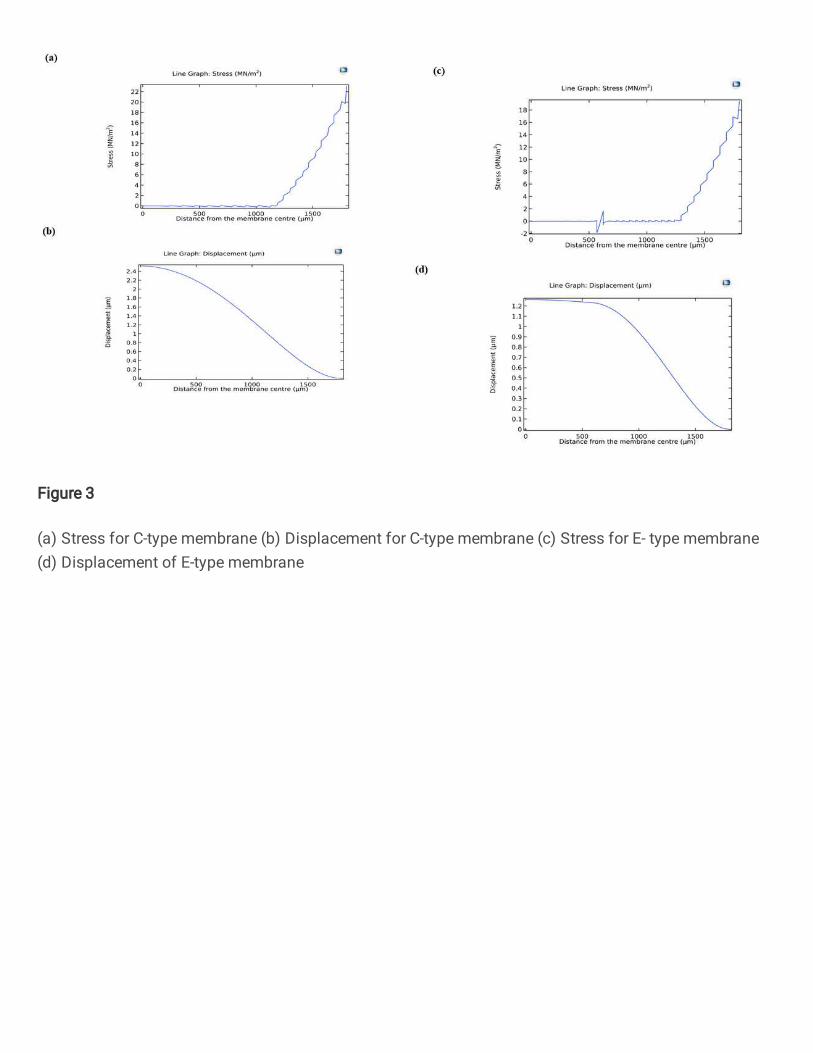
Figure 3
(a) Stress for C-type membrane (b) Displacement for C-type membrane (c) Stress for E- type membrane(d) Displacement of E-type membrane

Figure 4
(a) Stress for proposed membrane (b) Displacement for proposed membrane (c) Output vs. appliedpressure of proposed membrane (d) Non linearity vs. applied pressure for proposed membrane
Figure 5
(a) Von-Misses stress (b) Surface Stress distribution for proposed membrane

Figure 6
(a) Membrane de�ection without central mass (C-type) (b) Membrane de�ection with central mass (E-Type)