Design Analysis of Parts of Pelton Wheel Turbine P M V Subbarao Professor Mechanical Engineering...
53
Design Analysis of Parts of Pelton Wheel Turbine P M V Subbarao Professor Mechanical Engineering Department Selection of right parts and right geometry to execute Pure Impulse…..
-
Upload
zayne-bonifas -
Category
Documents
-
view
214 -
download
0
Transcript of Design Analysis of Parts of Pelton Wheel Turbine P M V Subbarao Professor Mechanical Engineering...

Design Analysis of Parts of Pelton Wheel Turbine
P M V SubbaraoProfessor
Mechanical Engineering Department
Selection of right parts and right geometry to execute Pure Impulse…..
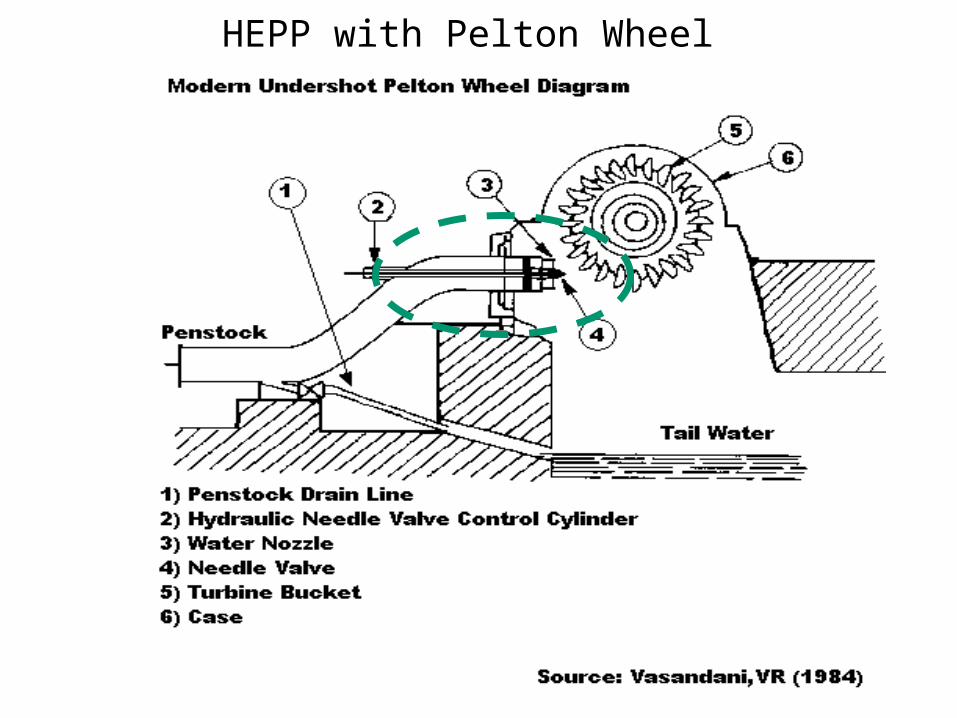
HEPP with Pelton Wheel

Parts of Pelton Turbine
• The main components of a Pelton turbine are:• (i) water distributor and casing, • (ii) nozzle and deflector with their operating mechanism, • (iii) runner with buckets, • (iv) shaft with bearing, • (v) auxiliary nozzle. • Auxiliary nozzle is used as brake for reducing the speed
during shut down. • The runner is located above maximum tail water to permit
operation at atmospheric pressure.

Key Parts of Pelton Turbine

Runner with Buckets• The runner consists of a circular disc with a number (usually more
than 15) of buckets evenly spaced around its periphery.
• Each bucket is divided vertically into two parts by a splitter that has a sharp edge at the centre and the buckets look like a double hemispherical cup.
• The striking jet of water is divided into two parts by the splitter.

• A notch made near the edge of the outer rim of each bucket is carefully sharpened to ensure a loss-free entry of the jet into the buckets,
• i.e., the path of the jet is not obstructed by the incoming buckets.

Bucket Displacement Diagram
Design of Nozzle is of Prime importance in Pelton Wheel

Nozzle used in 62.5 MW Pelton Wheel

Mechanism of Control of Jet dimensions

The Nozzle and Jet : A Key Step in Design
d0djet,VC
Velocity of the jet at VC:
gHV idealVCjet 2:,

gHKV vactualVCjet 21:, 99.098.0 1 vK
Jet carrying a discharge of Q to deliver a power P
gHKdQ vVCjet 24 1
2,
To generate a discharge of Q, we need a least jet diameter of
gHK
Qd
v
VCjet2
4
1
,
QgHP turbine

Diameter of the Jet at the outlet, do
gHKdQ voo 24
2
83.081.0 vOK
It is important to find out the VC and outlet jet diameters/areas

CFD Analysis of Free Jets & Flows In Air
P M V SubbaraoProfessor
Mechanical Engineering Department
A Consultancy Project Sponsored ByBHEL, Bhopal

The set of governing equations solved were primarily the continuity and the momentum equations.
These basic equations in Cartesian coordinate system for incompressible flows are given below,
( ) 0ii
ux
( )ij
i jj i j
Pu u
x x x
, ,
2
3ji
ij k k i jj i
uuu
x x
Turbulent Viscosity

Computational Grid : Nozzle

Contours of Volume Fractions : Nozzle Air Domain : 0.15m

Contours of Static Pressure : Nozzle Air Domain : 0.15m

Contours of Velocity Magnitude : Nozzle Air Domain : 0.15m

Contours of Volume Fractions : Air Domain : 0.3m

Contours of Volume Fractions : Air Domain : 1.0 m
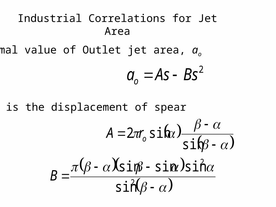
Industrial Correlations for Jet Area
Optimal value of Outlet jet area, ao
2BsAsao
s is the displacement of spear
sin
sin2 orA
2
2
sin
sinsinsinB

Pelton Wheel Distributor - CFD Analysis • The distributor to the Pelton wheel for the given geometry has
been simulated using Fluent in a 3-d viscous incompressible flow simulation.
• The set of governing equations solved were primarily the continuity and the momentum equations.
• The given geometry was meshed using the unstructured tetrahedral meshes due to geometrical complexity.
• An optimized tetrahedral mesh size of 25 was employed resulting in a a total of 62583 tetrahedral elements.

CAD Model of Distributor

Pelton Wheel Flow Distributor

Static Pressure Distribution
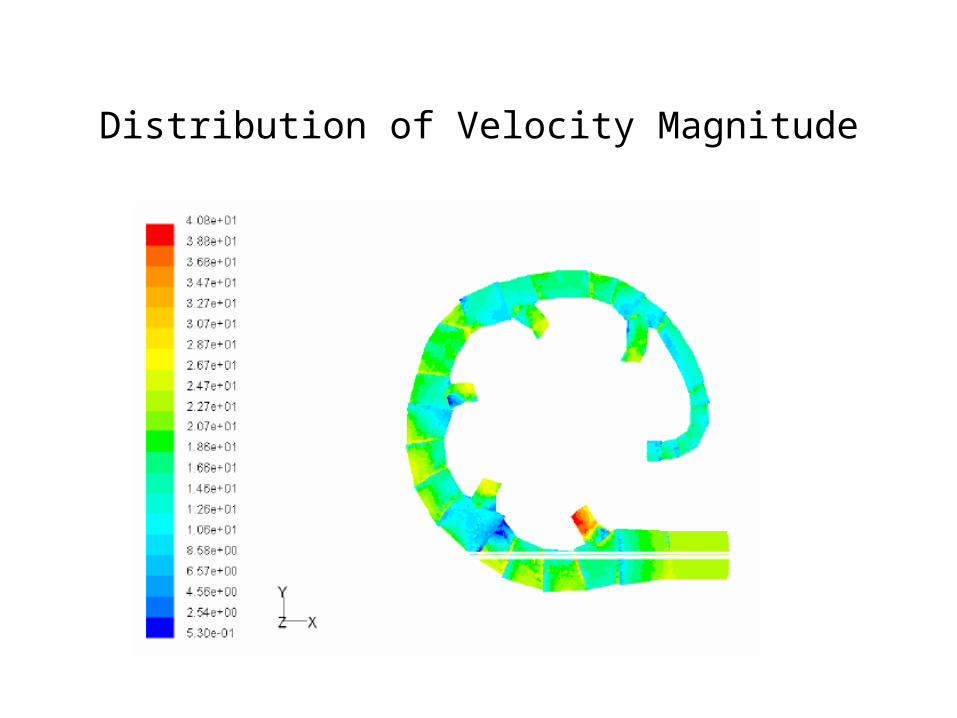
Distribution of Velocity Magnitude

Mean Diameter of Pelton Runner
Mean diameter or Pitch circle diameter:Dwheel
Circumferential velocity of the wheel, Uwheel
gHUwheel 2
gHKUwheeluwheel 2
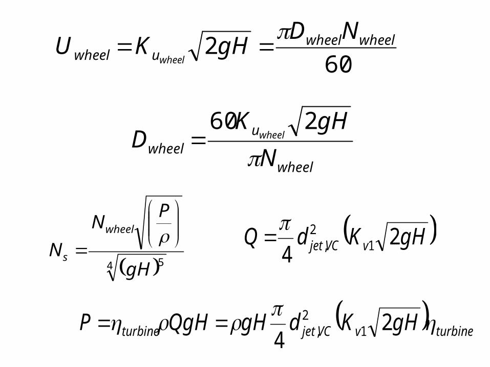
602 wheelwheel
uwheel
NDgHKU
wheel
wheel
uwheel N
gHKD wheel
260
4 5gH
PN
Nwheel
s
gHKdQ vVCjet 2
4 12
,
turbinevVCjetturbine gHKdgHQgHP 24 1
2,

4 5
12
, 24260
gH
gHKdgH
D
gHK
N
vVCjetturbine
wheel
u
s
wheel
12
,42
260vVCjetturbine
wheel
us Kd
D
KN wheel
wheel
VCjetvturbine
us D
dK
KN wheel ,
14 52
60

Experimental values of Wheel diameter to jet diameter
Dwheel /djet,VC 6.5 7.5 10 20
Ns (rpm) 35 32 24 10
turbine 0.82 0.86 0.89 0.90
45
H
PNN s P in hp, H in meters and N in rpm

For maximum efficiency, the ratio should be from 11 to 14.
The highest ratio used in the world is 110 (Kt. Glauraus Power House in Switzerland).
Specifications of this Pelton wheel are:
Power 3000HP (2.24MW) Speed: 500 rpmDwheel= 5.36m djet,VC=48.77mmHead =1,650 m
6.2
1650
30005004 54 5
gH
PN
Nwheel
s

Path Lines of Jet
D wheel
D pelton
dOVj,O
Number of buckets
• The number of buckets for a given runner must be determined so that no water particle is lost.
• Minimize the risks of detrimental interactions between the out flowing water particles and the adjacent buckets.
• The runner pitch is determined by the paths of; • the bucket tip (diameter Dpelton), the Wheel diameter (DWheel).• and the relative paths of the water particles stemming from the
upper and lower generators of the jet.• The bucket pitch must be selected so that no particle stemming
from the lower generator of the jet can escape the runner without encountering any bucket.

Bucket Duty Cycle
Reference Position

Zones of Bucket Duty Cycle
• i) Approach of the tip to the jet (θj < −40◦).
• ii) Initial feeding process : (θj = −40◦...−10◦).
• iii) Entire separation of the jet (θj = −10◦...0◦)
• iv) Last stage of inflow (θj = 0◦...15◦)
• v) Last stage of outflow (θj = 15◦...50◦).
• vi) Series of droplets (θj = −50◦...∞).

Start of Jet Bucket Interactions

Sequence of Jet Bucket Interactions

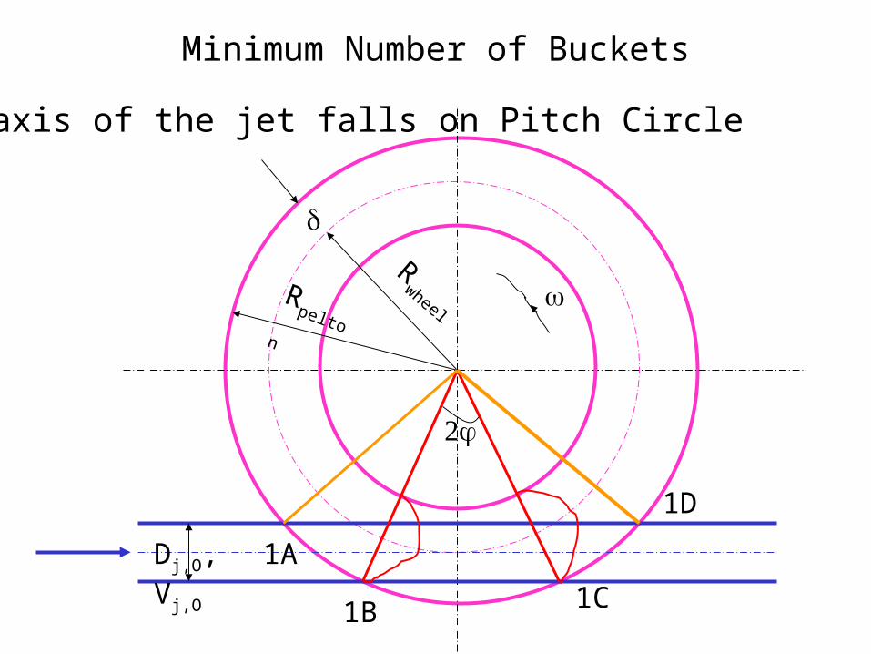
Minimum Number of Buckets
1B 1C
Rwheel
Rpelton
Dj,O, Vj,O
1A
1D
The axis of the jet falls on Pitch Circle

Minimum Number of Buckets
1B 1C1E
RwheelR
Pelton
dj,O, Vj,O

Minimum Number of Buckets
RW
heelRPelton
dO, Vj,O
lj
tj : Time taken bye the jet to travel lj
tb: Time taken by first bucket to travel

RWRP
dO, Vj,O
lj
sinpeltonj Dl
wheel
wheel
R
U
• tj = lj/Vjet,O
• tb =
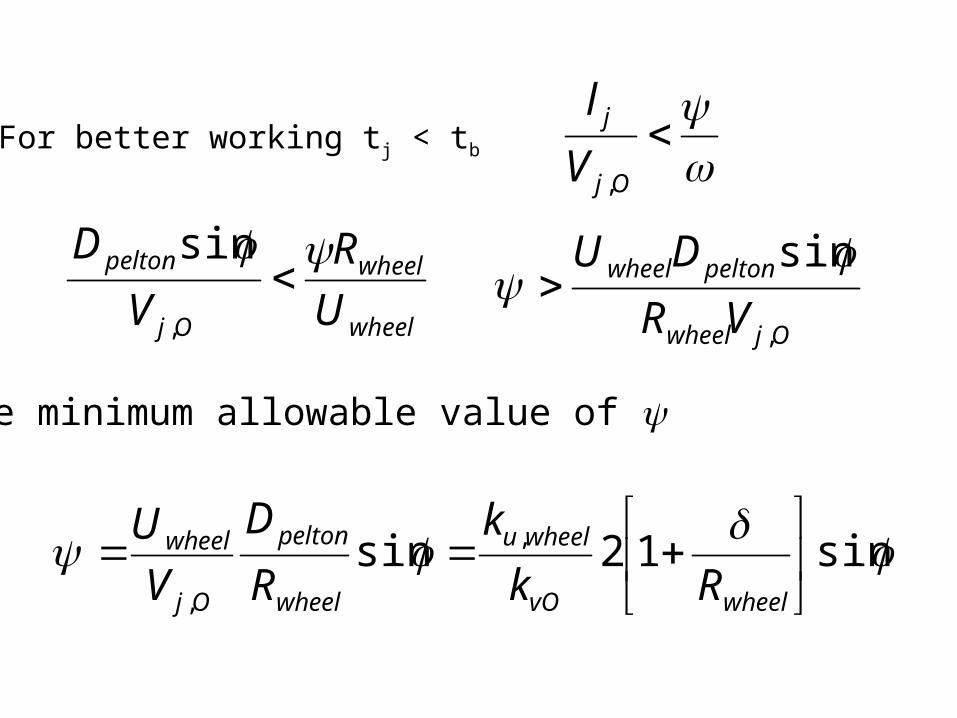
For better working tj < tb
Oj
j
V
l
,
wheel
wheel
Oj
pelton
U
R
V
D
,
sin
Ojwheel
peltonwheel
VR
DU
,
sin
The minimum allowable value of
sin12sin ,
,
wheelvO
wheelu
wheel
pelton
Oj
wheel
Rk
k
R
D
V
U

RWRP
dO, Vj,O
lj
pelton
Ojetwheel
R
dR
2cos
,
wheel
Ojetwheel
R
dR
2cos
,
wheel
wheel
Ojet
D
D
d
2
1
1
cos
,
wheel
VCjetvturbine
us D
dK
KN wheel ,
14
260
wheel
wheel
Ojet
D
D
d
2
1
1
cos
,

Maximum allowable angle between two successive buckets
2
Minimum number of buckets 360
z
Dr Taygun has suggested an empirical relation for z
155.0,
VCjet
wheel
d
Dz

Bucket Power Distribution
P(j)
1
2
34
5
Total

Bucket Energy Distribution
Ej,k
gHm
E
bucketthebyenergyWater
EnergyBucket
water
kk
h
dinterscpet
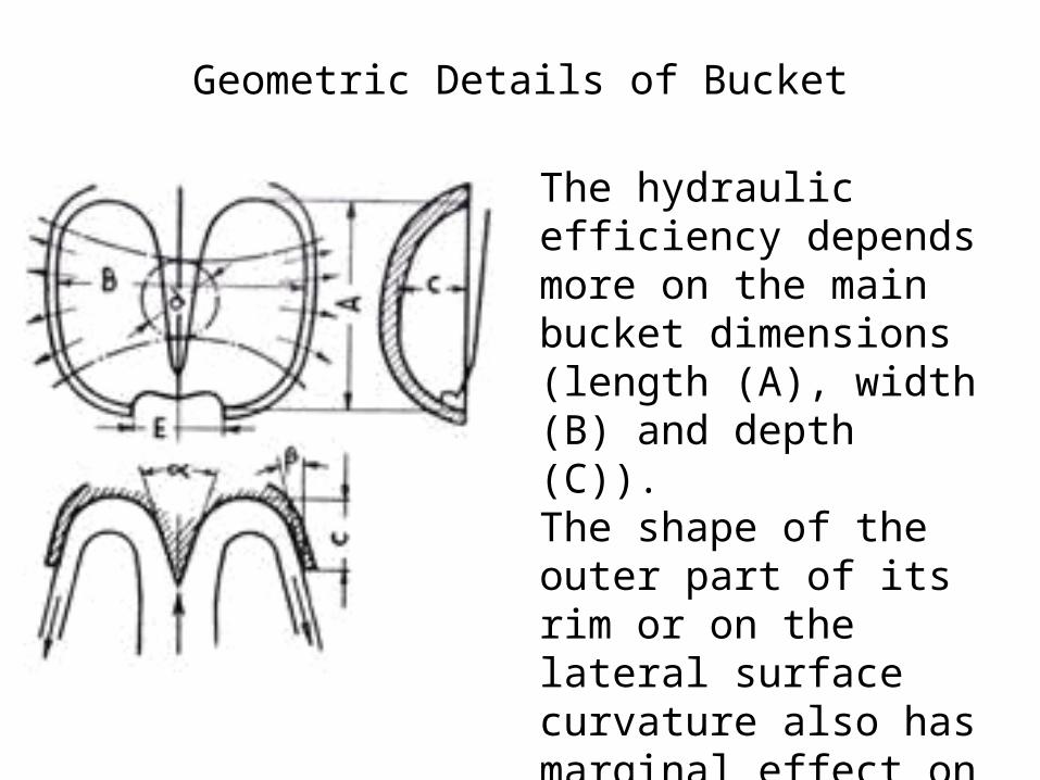
Geometric Details of Bucket
The hydraulic efficiency depends more on the main bucket dimensions (length (A), width (B) and depth (C)).The shape of the outer part of its rim or on the lateral surface curvature also has marginal effect on hydraulic efficiency.

Shape variations of Buckets

Design 1Design 2

Empirical Geometry of Bucket Shape
A
B
C
2i
e
S
I
IVII
III
V
DW

Empirical Relations for Bucket Geometry
• A = 2.8 djet,VC to 3.2 djet,VC
• B = 2.3 djet,VC to 2.8 djet,VC
• C= 0.6 djet,VC to 0.9 djet,VC
i = 50 to 80
e is varied from section I to section V
• I: 300 to 460
• II: 200 to 300
• III: 100 to 200
• IV: 50 to 160
• V: 00 to 50