Design Analysis of Furnace Of A Steam Generator P M V Subbarao Professor Mechanical Engineering...
21
Design Analysis of Furnace Of A Steam Generator P M V Subbarao Professor Mechanical Engineering Department Perfection of Primary Cause for All that Continues…..
-
Upload
steven-johnston -
Category
Documents
-
view
221 -
download
2
Transcript of Design Analysis of Furnace Of A Steam Generator P M V Subbarao Professor Mechanical Engineering...

Design Analysis of Furnace Of A Steam Generator
P M V SubbaraoProfessor
Mechanical Engineering Department
Perfection of Primary Cause for All that Continues…..

Basic Anatomy of A SG
Furnace
Convection Pass
Creation, Generation & Transfer of Thermal Energy
Transfer only
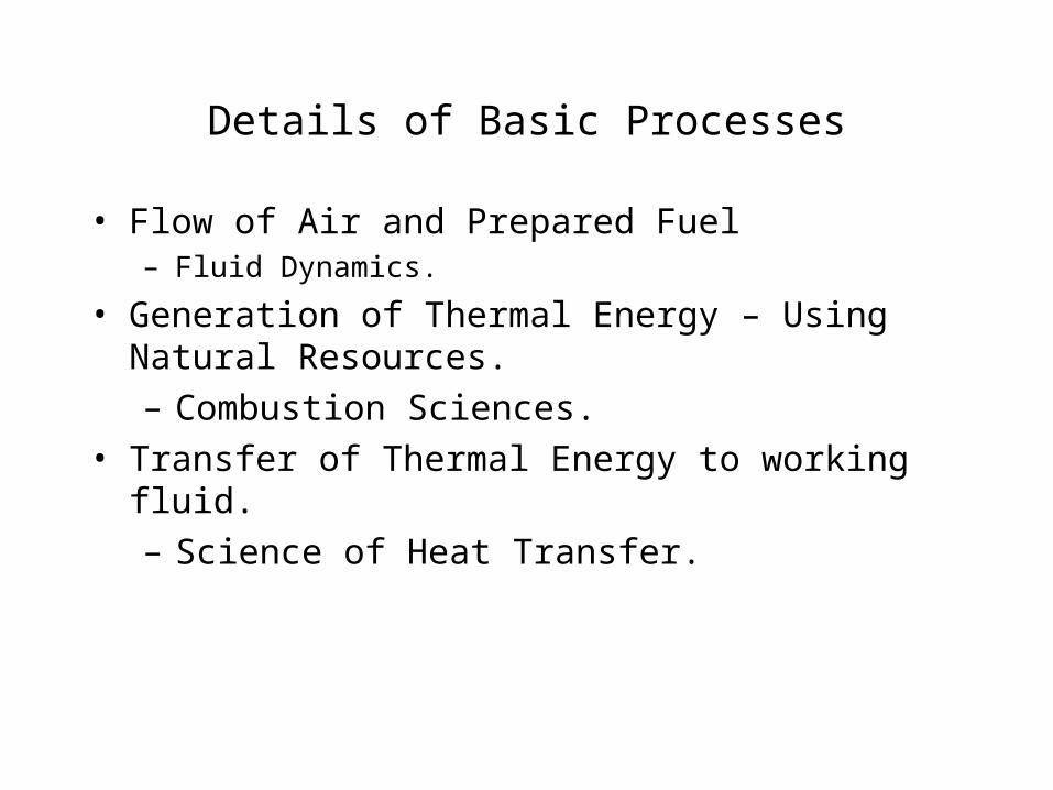
Details of Basic Processes
• Flow of Air and Prepared Fuel – Fluid Dynamics.
• Generation of Thermal Energy – Using Natural Resources.
– Combustion Sciences.
• Transfer of Thermal Energy to working fluid.
– Science of Heat Transfer.
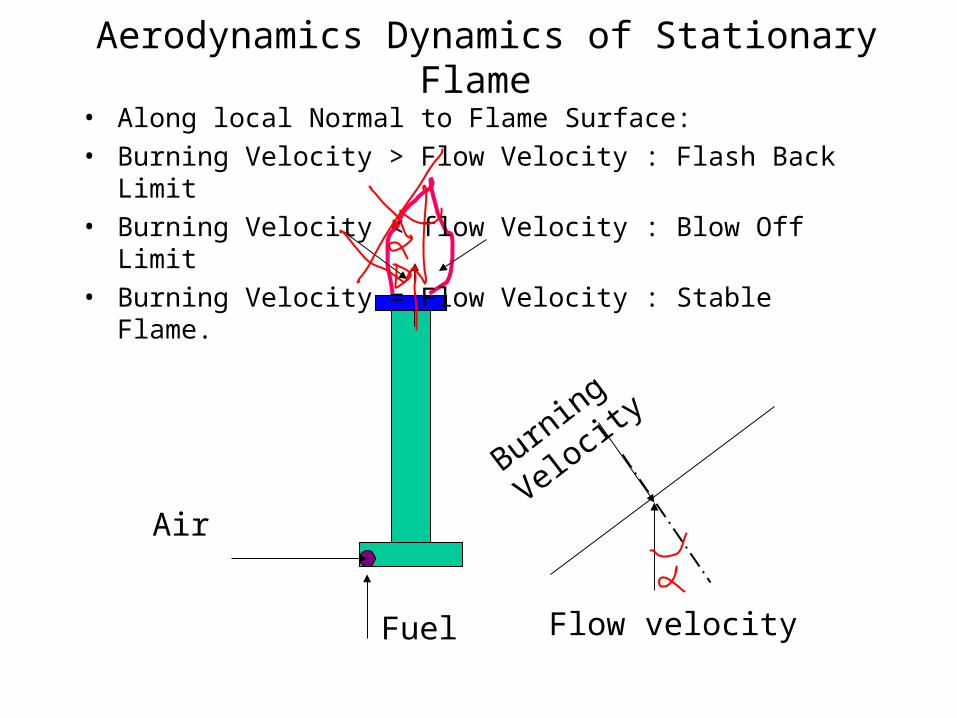
Aerodynamics Dynamics of Stationary Flame
Burning
Velocit
y
Fuel
Air
Flow velocity
• Along local Normal to Flame Surface:
• Burning Velocity > Flow Velocity : Flash Back Limit
• Burning Velocity < flow Velocity : Blow Off Limit
• Burning Velocity = Flow Velocity : Stable Flame.
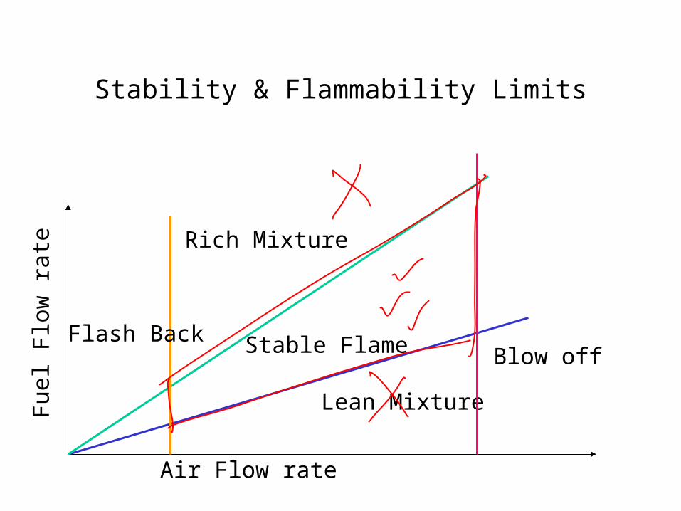
Stability & Flammability Limits
Air Flow rate
Fue
l Flo
w r
ate
Rich Mixture
Lean Mixture
Blow off Flash Back Stable Flame
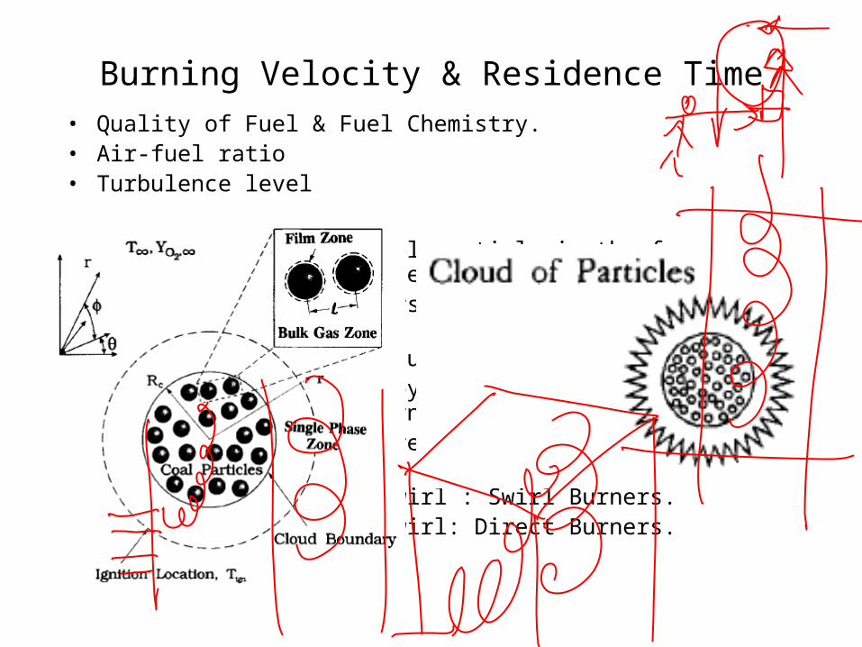
Burning Velocity & Residence Time
• Quality of Fuel & Fuel Chemistry.• Air-fuel ratio• Turbulence level
• Time to be spent by fuel particle in the furnace before it burns completely.
• Residence time is inversely proportional to burning velocity.• Fuel particle is continuously moving.• The distance traveled by the fuel particle should be much larger than
furnace height.• Swirl motion will ensure the required residence time.• Internally generated swirl : Swirl Burners.• Externally generated swirl: Direct Burners.

Basics of Coal Combustion: Burning Time
Coal is a complex organic polymer consisting of large polycyclic aromatic clusters of several fused rings strung together by assorted hydrocarbon chains of varying lengths and other hetroatom (O, N, S) linkages.
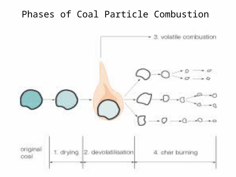
Phases of Coal Particle Combustion
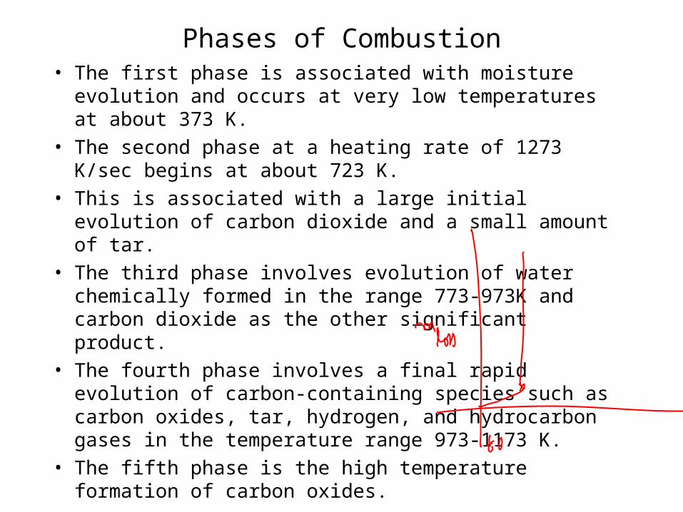
Phases of Combustion• The first phase is associated with moisture evolution and
occurs at very low temperatures at about 373 K.
• The second phase at a heating rate of 1273 K/sec begins at about 723 K.
• This is associated with a large initial evolution of carbon dioxide and a small amount of tar.
• The third phase involves evolution of water chemically formed in the range 773-973K and carbon dioxide as the other significant product.
• The fourth phase involves a final rapid evolution of carbon-containing species such as carbon oxides, tar, hydrogen, and hydrocarbon gases in the temperature range 973-1173 K.
• The fifth phase is the high temperature formation of carbon oxides.

Second Phase of Coal Combustion

Final Phase of Coal COmbustion
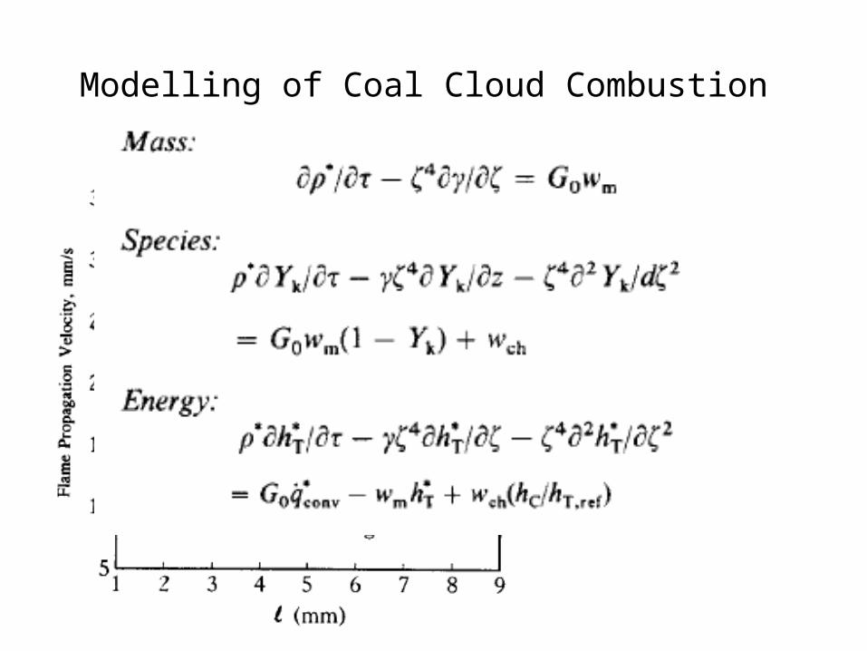
Modelling of Coal Cloud Combustion

Typical Flame Speed of PC.F
lam
e sp
eed
m/s
A/F ratio
30%VM & 5 % Ash
30%VM & 15 % Ash
30%VM & 30 % Ash
30%VM & 40 % Ash
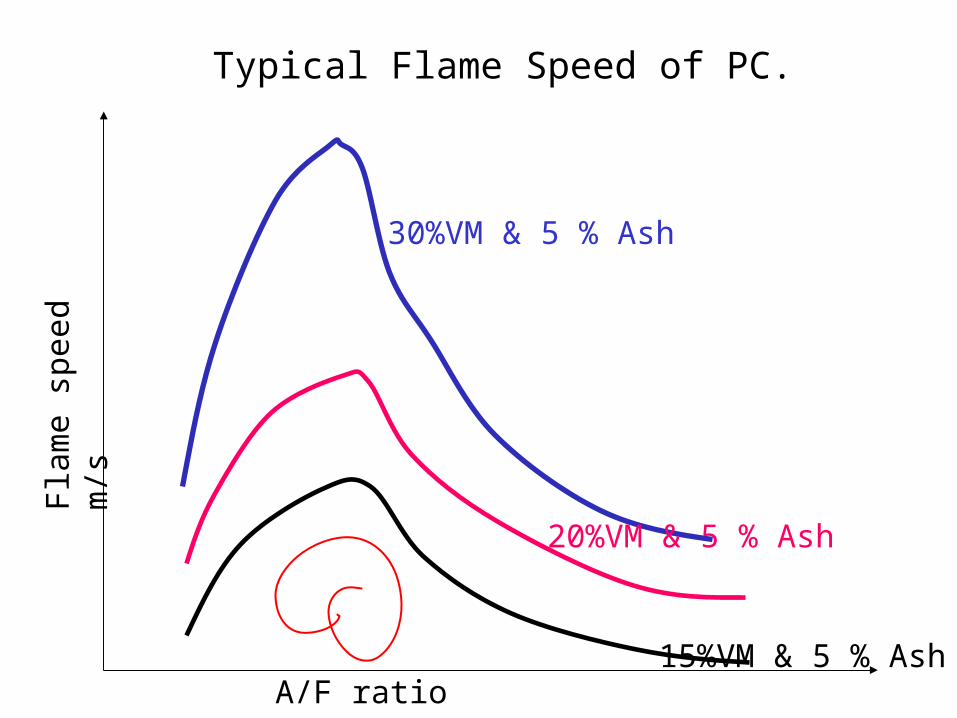
Typical Flame Speed of PC.F
lam
e sp
eed
m/s
A/F ratio
30%VM & 5 % Ash
20%VM & 5 % Ash
15%VM & 5 % Ash

Heat available for Radiation
• Incomplete combustion loss
• Unburned Carbon loss
• Loss due to slag
• Energy brought in by preheated air & fuel.
44wafleffflaislagCCOcfu TTAQQQQLHVmQ
COQ
slagQ
CQ
aiQ

Combustion Limits on Furnace Design
• The lower limit of the furnace volume is
• dominated by the space required for burning the fuel completely, or
• to an extent less than the allowable unburned fuel loss.
• To complete the fuel combustion within the furnace space, the fuel injected into the furnace has to reside there for a certain time longer than some critical time t*
r.
• The fuel residence time can be estimated by the residence time of the combustion gas produced in the furnace.
• An average residence time tr can be proposed.
eunit volumper generationheat of rate Allowable Max. furnace theof Volume
furnace theenteringenergy Fuel
rt
v
cr Vq
LHVmt
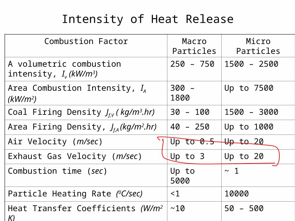
Combustion Factor Macro Particles
Micro Particles
A volumetric combustion intensity, Iv (kW/m3) 250 – 750 1500 – 2500
Area Combustion Intensity, IA (kW/m2) 300 – 1800 Up to 7500
Coal Firing Density Jf,V ( kg/m3.hr) 30 – 100 1500 – 3000
Area Firing Density, Jf,A (kg/m2.hr) 40 – 250 Up to 1000
Air Velocity (m/sec) Up to 0.5 Up to 20
Exhaust Gas Velocity (m/sec) Up to 3 Up to 20
Combustion time (sec) Up to 5000 ~ 1
Particle Heating Rate (0C/sec) <1 10000
Heat Transfer Coefficients (W/m2 K) ~10 50 – 500
Heat Fluxes to Heat exchange (kW/m2) ~ 10 50 – 500
Intensity of Heat Release

gas. ofdensity
generated gas of massV
vg
g
cr
qm
LHVmt
vc
g
gr
qm
m
LHVt
v
gr
qFA
LHVt
1

• Fuel combustion time is mainly dominated by the combustion reaction velocity and the rate at which oxygen is supplied into the reaction zone.
• The combustion reaction velocity depends on chemical characteristics of the fuel.
• Main technical factors that affect the combustion time are:
• Combustion characteristics of the fuel.
• Mixing characteristics.
• Fluid flow characteristics of the furnace.
• The combustion time of an oil fuel droplet is generally less than 0.1 msec.
• In the case of coal combustion time is much longer.

Design Constrains:Heat Release Rate
• Heat Release Rate per Unit Volume, qv, kW/m3
• Heat Release Rate per Unit Cross Sectional Area,qa, kW/m2
• Heat Release Rate per Unit Wall Area of the Burner Region, qb, kW/m2
• The maximum allowable heat flux of the water wall is restricted by its water-side burnout (dryout) heat flux.
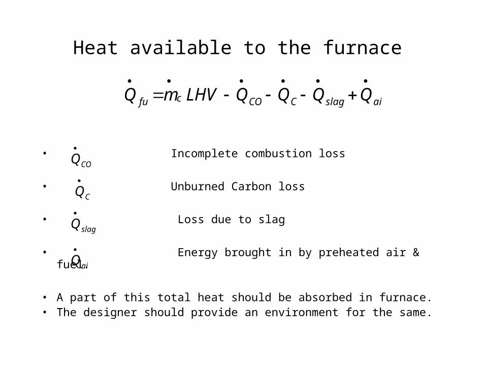
Heat available to the furnace
• Incomplete combustion loss
• Unburned Carbon loss
• Loss due to slag
• Energy brought in by preheated air & fuel.
• A part of this total heat should be absorbed in furnace.• The designer should provide an environment for the same.
aislagCCOcfu QQQQLHVmQ
COQ
slagQ
CQ
aiQ