DESIGN A WATER TANK SWITCHING SYSTEM VIMALSHWAREN...
102
DESIGN A WATER TANK SWITCHING SYSTEM VIMALSHWAREN A/L MAHALINGAM A project report submitted in partial fulfilment of the requirements for the award of the degree of Bachelor (Hons.) of Electrical & Electronics Engineering Faculty of Engineering and Science Universiti Tunku Abdul Rahman September 2011
Transcript of DESIGN A WATER TANK SWITCHING SYSTEM VIMALSHWAREN...

DESIGN A WATER TANK
SWITCHING SYSTEM
VIMALSHWAREN A/L MAHALINGAM
A project report submitted in partial fulfilment of the
requirements for the award of the degree of
Bachelor (Hons.) of Electrical & Electronics Engineering
Faculty of Engineering and Science
Universiti Tunku Abdul Rahman
September 2011

ii
DECLARATION
I hereby declare that this project report is based on my original work except for
citations and quotations which have been duly acknowledged. I also declare that it
has not been previously and concurrently submitted for any other degree or award at
UTAR or other institutions.
Signature : _________________________
Name : _________________________
ID No. : _________________________
Date : _________________________

iii
APPROVAL FOR SUBMISSION
I certify that this project report entitled “DESIGN A WATER TANK
SWITCHING SYSTEM” was prepared by VIMALSHWAREN A/L
MAHALINGAM has met the required standard for submission in partial fulfilment
of the requirements for the award of Bachelor (Hons.) of Electrical & Electronics
Engineering at Universiti Tunku Abdul Rahman.
Approved by,
Signature : _________________________
Supervisor : Dr. B.Balamuralithara
Date : _________________________

iv
The copyright of this report belongs to the author under the terms of the
copyright Act 1987 as qualified by Intellectual Property Policy of University Tunku
Abdul Rahman. Due acknowledgement shall always be made of the use of any
material contained in, or derived from, this report.
© 2011, Vimalshwaren A/L Mahalingam. All right reserved.

v
ACKNOWLEDGEMENTS
I would like to thank everyone who had contributed to the successful completion of
this project. I would like to express my gratitude to my research supervisor, Mr.
B.Balamuralithara for his invaluable advice, guidance and his enormous patience
throughout the development of the research.
In addition, I would also like to express my gratitude to my loving parent and
friends who had helped and given me encouragement an ideas to solve the problem
encounter during the completion of this project “Design a Water Tank Switching
System”.
I would like to take this opportunity to thank Midas Utara Engineering SDN
BHD, the company which I did internship for selling me second hand pumps for
cheaper price. This helped me to save a lot of cost to build this project.

vi
DESIGN A WATER TANK
SWITCHING SYSTEM
ABSTRACT
In the chapter one of this report which is the introduction part, the author has
discussed about how he got the idea to do this project which is the water tank
switching system and the main focus of this project. This project is titled “Design a
Water Tank Switching System”, so the main area of focus in this project is the
controlling unit of the system which is the electronic unit. Besides that the author has
also discussed about the aims and the objective of this project in the chapter one of
this report. In the second chapter of this report which is the literature review part, the
author has discussed about the mechanism and the main elements of a water tank
switching system. This includes the characteristic and nature of the main elements of
a water tank switching system. The third chapter is all about the methodology
involved in designing this water tank switching system. In this part the author has
discussed about the steps involved and things required in designing a water tank
switching system. The fourth chapter is all about the results obtained after designing
the water tank switching system and the discussion about the results. This includes
the experiment conducted to test the success of this water tank switching system. The
main objective of this project is to design a water tank switching system with
improved safety features and a system which can save power consumption, so these
objectives will be experimented and discussed in this chapter. The final chapter is
about the future recommendation that can be implemented to this water tank
switching system to improve its efficiency even further.

vii
TABLE OF CONTENTS
DECLARATION ii
APPROVAL FOR SUBMISSION iii
ACKNOWLEDGEMENTS v
ABSTRACT vi
TABLE OF CONTENTS vii
LIST OF TABLES ix
LIST OF FIGURES xi
LIST OF SYMBOLS / ABBREVIATIONS xiv
LIST OF APPENDICES xv
CHAPTER
1 INTRODUCTION 16
1.1 Background 16
1.2 Aims and Objectives 16
2 LITERATURE REVIEW 18
2.1 Electrical and Electronic Controlling Unit 18
2.2 Level Measurement Sensors 26
2.3 Pumps 32
2.4 Tank Systems 38

viii
3 METHODOLOGY 44
3.1 Functions of the Water Tank Switching System 44
3.2 Operational Principle of the Water Tank Switching System 45
3.3 Steps to Build the Entire System 47
3.3.1 Design and Build the Skid 48
3.3.2 Design and Build the Electrical and Electronic
Controlling Unit 49
3.3.3 Repair and Fix the Two Pumps to the Skid 64
3.3.4 Connect the Magnetic Level Float Switch 65
3.3.5 Test Run the Whole System 66
4 RESULTS AND DISCUSSIONS 67
4.1 General Discussion 67
4.2 Experiment 1 (Using 240V AC) 68
4.3 Experiment 2 (Using 24V DC) 74
4.4 Overall Discussion 79
5 CONCLUSION AND RECOMMENDATIONS 81
5.1 Conclusion 81
5.2 Future Recommendations 82
5.2.1 Have large capacity of storage tank 82
5.2.2 Have capability to pump more liquid 82
5.2.3 Have more precision of level measurement 83
5.2.4 Have alarm to alert in tank is not filled up 84
REFERENCES 85
APPENDICES 88

ix
LIST OF TABLES
TABLE TITLE PAGE
4.1 Time taken by pump A to pump 0.2 liters of water
and switch over to pump B at stroke length of
25 % 69
4.2 Time taken by pump A to pump 0.2 liters of water
and switch over to pump B at stroke length of
50 % 69
4.3 Time taken by pump A to pump 0.2 liters of water
and switch over to pump B at stroke length of
75 % 70
4.4 Time taken by pump A to pump 0.2 liters of water
and switch over to pump B at stroke length of
100% 70
4.5 Time taken by pump B to pump 0.2 liters of water
and switch over to pump A at stroke length of
25 % 72
4.6 Time taken by pump B to pump 0.2 liters of water
and switch over to pump A at stroke length of
50 % 72
4.7 Time taken by pump B to pump 0.2 liters of water
and switch over to pump A at stroke length of
75 % 72
4.8 Time taken by pump B to pump 0.2 liters of water
and switch over to pump A at stroke length of
100 % 73
4.9 Time taken by pump A to pump 0.2 liters of water
and switch over to pump B at stroke length of
25 % 74

x
4.10 Time taken by pump A to pump 0.2 liters of water
and switch over to pump B at stroke length of
50 % 75
4.11 Time taken by pump A to pump 0.2 liters of water
and switch over to pump B at stroke length of
75 % 75
4.12 Time taken by pump A to pump 0.2 liters of water
and switch over to pump B at stroke length of
100 % 75
4.13 Time taken by pump B to pump 0.2 liters of water
and switch over to pump A at stroke length of
25 % 77
4.14 Time taken by pump B to pump 0.2 liters of water
and switch over to pump A at stroke length of
50 % 77
4.15 Time taken by pump B to pump 0.2 liters of water
and switch over to pump A at stroke length of
75 % 77
4.16 Time taken by pump B to pump 0.2 liters of water
and switch over to pump A at stroke length of
100 % 78

xi
LIST OF FIGURES
FIGURE TITLE PAGE
2.1 ELCB 19
2.2 MCB 19
2.3 Relay 20
2.4 Circuit Diagram of an AC to DC Converter 21
2.5 AC-DC Converter 21
2.6 Circuit Diagram of a Dc to AC Inverter 22
2.7 DC-AC Converter 22
2.8 Circuit Diagram of an AC to AC Converter 23
2.9 AC-AC Converter 23
2.10 Circuit Diagram of a DC to DC Converter 24
2.11 DC-DC Converter 24
2.12 PLC 25
2.13 230V AC to 24V DC Power Supply 25
2.14 Float Switch 27
2.15 Conductivity Level Sensor 28
2.16 Magnetic Coupling Level Sensor 29
2.18 Magnetic Tracking Level Sensor 29
2.19 Vibrating Level Sensor 30
2.20 Guided Radar Level Sensor 31

xii
2.21 Magnetic Float Level Switch 31
2.22 AOD Pumps 33
2.23 Peristaltic Dosing Pump 34
2.24 Metering Dosing Pump 35
2.25 Rotary Gear Pump 36
2.26 Submersible Pump 37
2.27 Hot-Dip Galvanised Pressed Tank 39
2.28 FRP Tank 40
2.29 Steel Fused With Glass Tank 41
2.30 Sedimentation Tank 42
2.31 Hydropneumatic Tank System 43
3.1 The flow chart summarizing the whole system
operation 46
3.2 The flow chart summarizing the overall work load 47
3.3 AutoCAD drawing of the overall skid 48
3.4 The author is welding the PVC boards together 49
3.5 The flow chart summarizing the whole system
operation 50
3.6 The Electrical Diagram of the Tank Switching
System 51
3.7 Ladder Diagram when Initial State 52
3.8 Ladder Diagram when Sensor A Triggered 53
3.9 Ladder Diagram when the Tank A is Filled Up 54
3.10 The Ladder Diagram when Sensor B Triggered 55
3.11 Ladder Diagram when the Tank B is Filled Up 56
3.12 The Omron Set/Reset Relay 57
3.13 Relpol 24V DC relay 59

xiii
3.14 24V DC Power Supply 60
3.15 Omron Set/Reset Relay Socket 61
3.16 Relpol 24V DC Relay Socket 61
3.17 ELCB 62
3.18 Isolator Switch 62
3.19 Wire Terminal Block 63
3.20 PVC 310x230x145 Junction Box 63
3.21 The faulty electronic card of one of the pumps 65
3.22 Magnetic Level Float Switch with Holder 66
4.1 Performance of the Tank Switching System
Powered by 240V AC measured in terms of Time
taken by pump A to pump 0.2 liters of water and
switch over to pump B at four different stroke
lengths 71
4.2 Performance of the Tank Switching System
Powered by 240V AC measured in terms of Time
taken by pump B to pump 0.2 liters of water and
switch over to pump A at four different stroke
lengths 73
4.3 Performance of the Tank Switching System with
24 V DC Power Supply measured in terms of Time
taken by pump A to pump 0.2 liters of water and
switch over to pump B at four different stroke
lengths 76
4.4 Performance of the Tank Switching System with
24 V DC Power Supply measured in terms of Time
taken by pump B to pump 0.2 liters of water and
switch over to pump A at four different stroke
lengths 78

xiv
LIST OF SYMBOLS / ABBREVIATIONS
cp specific heat capacity, J/(kg⋅K)
h height, m
Kd discharge coefficient
M mass flow rate, kg/s
P pressure, kPa
Pb back pressure, kPa
R mass flow rate ratio
T temperature, K
v specific volume, m3
α homogeneous void fraction
η pressure ratio
ρ density, kg/m3
ω compressible flow parameter
ID inner diameter, m
MAP maximum allowable pressure, kPa
MAWP maximum allowable working pressure, kPa
OD outer diameter, m
RV relief valve

xv
LIST OF APPENDICES
APPENDIX TITLE PAGE
A Data Sheet of the 24 V DC power supply 88
B Data Sheet of the 24 V DC Relpol relay 91
C Data Sheet of the 240 V AC Omron relay 97
D Data Sheet of the magnetic level float switch
sensor 100

16
CHAPTER 1
1 INTRODUCTION
1.1 Background
The tank system which is available in industries now has a drawback. The drawback
is, each time the tank becomes empty, the user have to fill up the tank so that the
process which depends on the liquid in the tank doesn’t not get interrupted. So if the
liquid finishes during midnight or during public holidays, then the any industrial
processes which depend on the liquid will be interrupted. To rectify this drawback,
the author has designed this tank switching system. If the liquid in a tank finishes,
there will be a backup tank whereby the electrical and electronic controlling unit will
switch over the dosing of the liquid from the first tank to the second tank
automatically. Therefore, any crucial process doesn’t get interrupted. Again after the
liquid in the second tank finishes, the system will switch the dosing of liquid back to
the first tank if the liquid in the first tank is topped up by the user.
1.2 Aims and Objectives
The main aim of the author to do this final year project is to design a water tank
switching system by using electrical and electronic components such as DC power
supply, relays and ELCB. Therefore the main area focused by the author in this
project is the electrical and electronic controlling unit which is build to run the whole
system. Besides that the author will also focus on the magnetic level switch sensor

17
and the pump which is attached to the sensor. In this project the pump is like the
indicator, whereby when the low level is detected it will stop and switch over to the
other pump.
The objective of this final year project is:
a. To enhance the safety features in tank switching systems by using 24V DC
power supply to power the sensors.

18
CHAPTER 2
2 LITERATURE REVIEW
2.1 Electrical and Electronic Controlling Unit
Electrical and electronic controlling unit is basically used for every control process
and there are many types of electrical and electronic controlling unit in use at
industries. Electrical and electronic controlling unit can only be designed based on
the particular process that we desire to control. To design an electrical and electronic
controlling unit, first we need to the process flow of the particular system that we
wish to control. After that we have to put the flow and description into electrical
drawing. After coming up with electrical drawing, then we have to start building the
electrical panel. There are few basic electronic components which are used in the
electrical panel such as listed below.
2.1.1 Earth Leakage Circuit Breaker (ELCB) (Mitchel, E.S.2006)
This is used as a protective measure to shut the system down in case of any
draw backs. It has a very high earth impedance to prevent shock. The ELCB detects
fault currents from live (hot) to the earth (ground) wire within the installation it
protects. If sufficient voltage appears across the ELCB's sense coil, it will switch off
the power, and remain off until manually reset. An ELCB however, does not sense
fault currents from live to any other earthed body.

19
Figure 2.1: ELCB (ELCB, 2011)
2.1.2 Miniature Circuit Breaker (MCB)
(Mitchel, E.S.2006) revealed a MCB is an automatically operated electrical
switch designed to protect an electrical circuit from damage caused by overload or
short circuit. Its basic function is to detect a fault condition and, by interrupting
continuity, to immediately discontinue electrical flow. A MCB can be reset (either
manually or automatically) to resume normal operation.
Figure 2.2: MCB (ELCB, 2011)

20
2.1.3 Relays (Mitchel, E.S.2006)
A relay is an electrically operated switch. Many relays use an electromagnet
to operate a switching mechanism mechanically, but other operating principles are
also used. Relays are used where it is necessary to control a circuit by a low-power
signal (with complete electrical isolation between control and controlled circuits), or
where several circuits must be controlled by one signal.
Figure 2.3: Relay (John Hewes, 2011)
2.1.4 Invertors/ Converters
According to Ned, M. et al. (2006), Invertors and convertors are used to convert
either AC to DC, DC to AC, AC to AC or DC to DC. This are used to either boost up
the current, reduce the current, convert from either DC to AC form or otherwise.
a) AC to DC Converters (Ned, M. Et al. (2006))
A single phase converter with two natural commutated thyristor is shown.
The average value of the output voltage vo can be controlled by varying the

21
conduction time of thyristor or firing delay angle α . The input may be single or three
phase source. These converters are also known as controlled rectifier.
Figure 2.4: Circuit Diagram of an AC to DC Converter (Ned, M. et al.(2006)
Figure 2.5: AC-DC Converter
b) DC to AC Inverter (Ned, M. et al.(2006))
A single phase transistor inverter is shown below. If transistors M1 and M2
conduct one half of a period and M3 and M4 conduct for the other half, the output
voltage is of the alternating form. The output voltage can be controlled by varying
the conduction time of transistors.

22
Figure 2.6: circuit Diagram of a DC to AC Inverter (Ned, M. et al. (2006))
Figure 2.7: DC-AC Converter
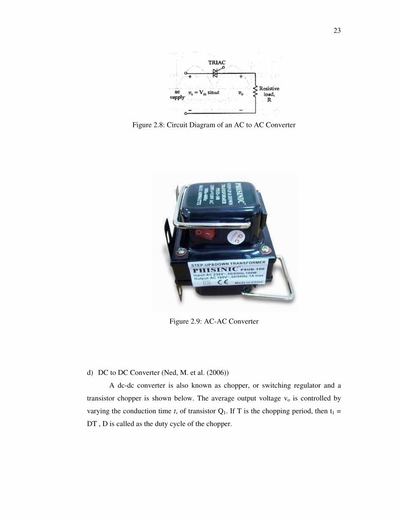
c) AC to AC Converter (Ned, M. et al.(2006))
These converters are used to obtain a variable ac output voltage vo from a
fixed ac source and a single phase converter with TRIAC is shown. The output
voltage is controlled by varying the conduction time of a TRIAC or firing delay
angle α . These types of converter are also known as ac voltage controllers.
23
Figure 2.8: Circuit Diagram of an AC to AC Converter
Figure 2.9: AC-AC Converter
d) DC to DC Converter (Ned, M. et al. (2006))
A dc-dc converter is also known as chopper, or switching regulator and a
transistor chopper is shown below. The average output voltage vo is controlled by
varying the conduction time t, of transistor Q1. If T is the chopping period, then t1 =
DT , D is called as the duty cycle of the chopper.

24
Figure 2.10: Circuit Diagram of a DC to DC Converter (Ned, M. et al. (2006))
Figure 2.11: DC-DC Converter
2.1.5 Programmable Logic Control (PLC) (Mitchel, E.S.(2006))
In some high end electrical panels and systems which require precise
calculation and measurements, PLC is used. PLC is very handy when it comes to
system which gives importance for precision.

25
Figure 2.12: PLC (Mitchel, E.S.(2006))
2.1.6 24 V DC Power Supply (Mitchel, E.S.(2006))
This component reduces a 230V AC voltage to a 24V DC voltage and with
earthing features. This device also gives us a possibility to push up the current in
case the reduced current is not sufficient enough for certain functions.
Figure 2.13: 230V AC to 24V DC Power Supply

26
2.2 Level Measurement Sensors
Level measurement sensors are typically used for the following application:
(Endress &Hauser,2005)
a) Cleaning and filtering systems
b) Coolant and lubricant tanks
c) Overspill protection tanks
d) Tanks with pump application
e) Liquid level limit detection in tanks
f) Liquid level detections in pipes
There are many types of level measuring sensors such as below:
(Endress &Hauser,2005)
2.2.1 Float switch
This type of level sensors can be used for level switch from drinking water to sewage
water. It has fail-safe indication and pump control. The main advantage of this type
of level sensors is it has low specific weight of the floating body; therefore it can be
used in any environment or condition. It is also low cost polypropylene level switch.
These types of sensors are also mercury free operated micro switch.

27
Figure 2.14: Float Switch (Float Switch and Liquid Level Sensor Products, (2002))
2.2.2 Conductivity Level Sensor
Conductive level sensors can be used in conductive liquids. There will be a voltage
flowing in the sensor and it is exposed to the liquid. Therefore it has to be carefully
used as it is dangerous. If let us say there is a flammable gas around the sensor, it
may cause explosion due to exposure to the sensor. It has types in it, one which is
limit switch and another one which is the differential switch. It also comes with high
or low fail-safe mode.

28
Figure 2.15: Conductivity Level Sensor (Level Switches, (2011))
2.2.3 Magnetic Coupling Level Sensor
This type of sensor is widely used in power stations, chemical, pharmaceutical and
petrochemical industries. This sensor is also used in balance tanks on ships. This can
be operated without power supply as well and it has a separated micro-switch. This
model of sensor is explosion proof models. It works in a pair, when the first sensor is
triggered, a pulse will be send and when the second sensor is sensed then the liquid
flow out will be stopped and liquid flow in will start.

29
Figure 2.16: Magnetic Coupling Level Sensor (Level Switches, (2011))
2.2.4 Magnetic Tracking Level Sensor
This type of sensor is used for liquids which have dense vapour or gas layer above
the surface. It is a multi-point level switch which is placed in closed tanks. This
sensor can also be operated without power supply and it is an explosion proof model.
Figure 2.18: Magnetic Tracking Level Sensor (Level Switches, (2011))

30
2.2.5 Vibrating Level Sensors
This type of sensor is used for corrosive, thick, turbulent and flowing liquids. This
sensor can also be used for powders and light granules. It has high immunity against
vibration and it has no moving parts. It has option to choose various density level and
it is an explosion proof model too.
Figure 2.19: Vibrating Level Sensor (Level Switches, (2011))
2.2.6 Guided Radar Level Sensor
It is a proximity switch or transmitter for positioning equipment, packaging
equipment and filling equipment. It comes with a switch and also a transmitter and it
is a fully temperature compensated unit.

31
Figure 2.20: Guided Radar Level Sensor (Sensors, (2009))
2.2.7 Magnetic float level switch
This type of liquid level sensor is the most compact level sensor used in single level
detection. This sensor has to be mounted vertically for best results in the top or
bottom of a tank or reservoir. This sensor comes standard with a PVC cable with a
cross section of 0.14 mm2 and a length of 500 mm. This sensor is widely used for
level control, level detection and monitoring, test and measurement and since it is
made of plastic it can be used for any type of liquid expect petrol based liquids. This
type of sensor is also the safe type of sensor because it is fully insulated and there
will not be any electrical leakage into the tank.
Figure 2.21: Magnetic Float Level Switch

32
2.3 Pumps
2.3.1 Air Operated Diaphragm Pumps (Babbit et al. 1962)
Air operated Diaphragm (AOD) pumps are a popular choice in wide range of
applications for reasons as below:
a) Simple installation
b) Exceptional tolerance to variation in operating conditions
c) Ability to handle problem media
d) Low initial cost
AODs pump virtually anything that flows from water, viscous, corrosive and
even abrasive sludge and even some dry powders. This type of pump is seal less, self
priming and inherently variable speed. This type of pump has been very reliable to
plant engineers.
AOD pumps work by using compressed air to displace liquids. As the
diaphragm reciprocates the volume of the vessel alternately expands and contracts,
filling with fluids and then expelling the fluids. The valves control the flow to ensure
that the cavity fills from the pump inlet and the fluid is expelled. The air control
mechanism functions alternately to pressurize and exhaust the air side of the
diaphragm.

33
Figure 2.22: AOD Pumps (Karassik et al. 2001)
2.3.2 Peristaltic Pumps
According to Karassik et al. (2001), the most important advantage of peristaltic
pump is their use of tubing as the pump chamber. The fluid is inside the tubing and
does not contaminate the pump, nor does the tubing contaminate the fluid. Cleaning
up requires only the change of tubing. This saves cost and maintenance time.
Peristaltic pump transfers fluid successfully in industries such as food processing,
pharmaceutical manufacturing, chemical processing, laboratory research, and
agriculture and water treatment.
Peristaltic pump works on simple principle, the alternating pattern of
squeezing and releasing the tubing moves the fluid through the pump. As the roller
passes over the tubing, it is first occluded then released. The progression of this
squeezed area forces the fluid to move in front of the roller. The tubing behind the
rollers recovers its shape, creating vacuum which draws fluid in behind it. As the
roller moves faster, vacuum pockets are created more quickly and the fluid moving
through the system picks up speed. The rollers act as check valves to prevent
siphoning or loss of prime.

34
Figure 2.23: Peristaltic Dosing Pump
2.3.3 Metering Pumps
(Karassik et al. 2001) revealed that metering pumps are used whenever it is
necessary to pump accurate quantities of liquid. Metering pumps can handle a wide
range of fluids, ranging from acids, caustics and corrosive, polymers and in both
continuous and batch control process.
Metering pumps has the following advantages:
a) High accuracy
b) High pressure
c) Low flow
d) Pump flow independent of system pressure
e) Leakage free
f) Extended dry run capability
g) Handling of toxic, hazardous or high temperature fluids
35
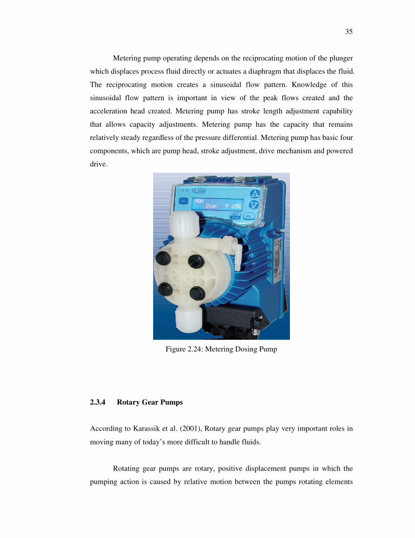
Metering pump operating depends on the reciprocating motion of the plunger
which displaces process fluid directly or actuates a diaphragm that displaces the fluid.
The reciprocating motion creates a sinusoidal flow pattern. Knowledge of this
sinusoidal flow pattern is important in view of the peak flows created and the
acceleration head created. Metering pump has stroke length adjustment capability
that allows capacity adjustments. Metering pump has the capacity that remains
relatively steady regardless of the pressure differential. Metering pump has basic four
components, which are pump head, stroke adjustment, drive mechanism and powered
drive.
Figure 2.24: Metering Dosing Pump
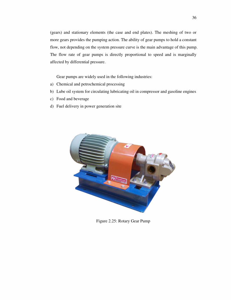
2.3.4 Rotary Gear Pumps
According to Karassik et al. (2001), Rotary gear pumps play very important roles in
moving many of today’s more difficult to handle fluids.
Rotating gear pumps are rotary, positive displacement pumps in which the
pumping action is caused by relative motion between the pumps rotating elements
36
(gears) and stationary elements (the case and end plates). The meshing of two or
more gears provides the pumping action. The ability of gear pumps to hold a constant
flow, not depending on the system pressure curve is the main advantage of this pump.
The flow rate of gear pumps is directly proportional to speed and is marginally
affected by differential pressure.
Gear pumps are widely used in the following industries:
a) Chemical and petrochemical processing
b) Lube oil system for circulating lubricating oil in compressor and gasoline engines
c) Food and beverage
d) Fuel delivery in power generation site
Figure 2.25: Rotary Gear Pump

37
2.3.5 Submersible Pump
Karassik et al. (2001) reported a submersible pump is a device which has a sealed
motor close-coupled to the pump body. The whole assembly is submerged in the
fluid to be pumped. The main advantage of this type of pump is that it prevents pump
cavitations, a problem associated with a high elevation difference between pump and
the fluid surface. Submersible pumps push fluid to the surface.
The main operational mechanism is by the centrifugal force created by
rotational speed of the impeller. The fluid will slowly lose their kinetic energy in the
diffuser where a conversion of kinetic to pressure energy takes place. The pump shaft
is connected to the gas separator or the protector by a mechanical coupling at the
bottom of the pump. Fluids enter the pump through an intake screen and are lifted by
the pump stages. Other parts include the radial bearings (bushings) distributed along
the length of the shaft providing radial support to the pump shaft turning at high
rotational speeds. An optional thrust bearing takes up part of the axial forces arising
in the pump but most of those forces are absorbed by the protector’s thrust bearing.
This type of pump is widely used in water wells, oil wells and also in sewage
tanks to pump up the sludge.
Figure 2.26: Submersible Pump

38
2.4 Tank Systems
There are few general functions of tank systems. They are: (Babbit et al, 1962)
a. To provide a reserve of water in order to minimize interruption of supply due
to breakdown.
b. To provide a reserve to meet a fluctuating demand.
c. To act as a break pressure tank where the range of elevation of an area served
makes it necessary to sub-divide the distribution system into zones.
d. To provide a reserve of water for fire fighting. The amount of contingency
storage to be provided determines the size of the tank.
A sump in tank systems is a low space that collects any often-undesirable
liquids such as water or chemicals. Usually a sump can be also used to collect water
or used as a reservoir below ground which is in the underground level. A sump can
also be an infiltration basin used to manage surface runoff water and recharge
underground aquifers.
2.1.1 Water Distribution Tank System
In water distribution system, tanks systems functions can be divided into two main
categories: (Babbit et al, 1962)
A. Balancing tanks
B. Service tanks
Generally the main function of balancing tanks is to receive treated water and
to distribute it substantially to service tanks.
Balancing tanks are normally built near treatment plants. When there is a
draw-off from any of the service tanks, water will flow from the balancing tanks to
the service tanks to balance up the draw-off. With the provision of the balancing tank

39
in the distribution system, the required flow rate into the service tank can be
maintained.
The total minimum capacity of any tank system should preferably equivalent
to one day’s storage. The one day storage will normally meet the fire fighting
requirement.
There are many types of tanks available in the market. For instance:-
1. Galvanised Pressed Steel Tank (Babbit et al ,1962)
This type of tank is readily available in the market and relatively cheaper compared
to any other tanks. In order to minimize corrosion that may occur over the years, the
pressed steel tank should be hot-dip galvanised and the bolts and nuts within the tank
should be made of stainless steel.
Figure 2.27: Hot-Dip Galvanised Pressed Tank

40
2. Fiberglass Reinforced Polyester (FRP) Tank
According to (Babbit et al ,1962), although this type of tank is expensive compared
to other type of tanks, but it offer the following advantages:
a. Minimum maintenance needed because the tank panels are non-
corrodable.
b. The tank can be easily and quickly erected. It can be assembled
precisely according to the requirements owing to the available range
of the panels with varying strength and sizes.
c. Due to the light weight of the tank, it is possible to provide
economical supporting structures.
Figure 2.28: FRP Tank
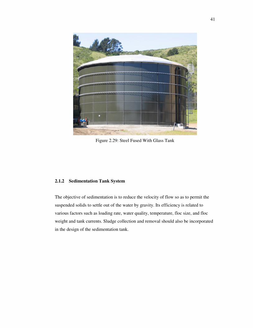
3. Steel Fused With Glass Tanks (Babbit et al ,1962)
The tank plate material is basically steel fused with glass resulting in a smooth, low
friction, hard impervious surface which requires low maintenance. This type of tank
can be used at ground level or elevated on steel or reinforced concrete structures.
41
Figure 2.29: Steel Fused With Glass Tank
2.1.2 Sedimentation Tank System
The objective of sedimentation is to reduce the velocity of flow so as to permit the
suspended solids to settle out of the water by gravity. Its efficiency is related to
various factors such as loading rate, water quality, temperature, floc size, and floc
weight and tank currents. Sludge collection and removal should also be incorporated
in the design of the sedimentation tank.

42
Figure 2.30: Sedimentation Tank
There are 3 types of sedimentation tanks. They are:
i. Horizontal Type Sedimentation Tank
ii. Lovo Sedimentation Tank
iii. Vertical Sedimentation Tank

43
2.1.3 Hydro-pneumatic Tank System
According to (Babbit et al ,1962), there are several different functions that a hydro-
pneumatic tank can perform. In a booster pump application, it can provide water to
the system during periods of a no flow shutdown of the booster pump or it can
provide water to replace leak loads. In a well water application, it can provide the
desired volume of water required between the pump shut down pressure and the
pump turn on pressure. In a sprinkler or irrigation pump application, the tank may
provide a cushion to maintain necessary pressure so the jockey pump will not short
cycle. In any case, the amount of water that the tank will be required to supply to the
system during any given cycle is called the drawdown. Drawdown must first be
determined to properly size the hydro-pneumatic tank. Water is pumped from the
domestic supply system into a pressure tank for storage. Air in the tank is
compressed by the water entering the tank. As the pressure in the tank increases, the
pressure in the water distribution system also increases, since it is fed from the tank.
Figure 2.31: Hydropneumatic Tank System (Babbit et al ,1962)

44
CHAPTER 3
3 METHODOLOGY
3.1 Functions of the Water Tank Switching System
The water tank switching system which the author has designed has many versatile
functions and offers a wide range of applications such as:
1. Back up supply system in crucial places like hospitals. If at all, there is a
water supply interruption in hospitals, when the main supply water finishes in
the main supply tank, then this system can be used to switch the water supply
to the reserve tank.
2. This system can also be used in high rise residential areas. When there is a
water interruption in high rise buildings, it will take a while for the water to
fill up the main tank. Therefore this system comes in handy, where when the
water level drops below the low level in the main tank during the water
interruption, the water supply will be switched to the backup tank. Then
while the water is being filled back in the main tank, supply will be going
from the back up tank till the water in the back up tank drops below the low
level and then it will switch back to main tank automatically.
3. This system can be used in restaurants as well. In restaurant the supply of
soap water is very crucial when it comes to cleaning and washing the utensils.
So this system can be used to have constant soap water supply for the whole
day. This means the restaurant workers just need to mix the soap water once
in the day which is in the morning only. So when the soap water in the
primary tank finishes, then the relay will trigger to switch the pump to dose

45
the soap water from the back up tank. This saves a lot of time and hassle in
the restaurant management.
4. This system can also be used for industry applications whereby this system
can be used to supply a constant chemical dosing for a certain process in
industrial. This means the dosing of chemical will not be interrupted for the
whole process. Workers just need to top up the chemical or liquid once a day
either in the morning or in the evening. This means when the chemical or
liquid supply finishes from the main tank, the dosing of chemical or liquid
will be switched to the back up tank. Once the chemical or liquid in main
tank is filled up, the system will switch over to the main tank back provided
the chemical or liquid in the back up tank has dropped below the low level of
the sensor.
One of the many big advantages that this system offers is, the duration of the
whole system can be varied by adjusting the speed of the pump. In addition to this,
the capacity of the backup tanks can also be varied. The bigger the capacity of the
backup tank, the system can run for longer time in the backup system.
3.2 Operational Principle of the Water Tank Switching System
The main characteristic of the water tank switching system which the author has
designed is a system which used relays as its main control element. When the liquid
in the main tank drops below the low level and it’s detected by the magnetic level
float switch in it, the relay will be triggered. This relay in return will trigger the
set/reset relay which will switch the dosing of the liquid to the backup tank.
When the liquid in the back up tank drops below the low level and detected
this low level detected by the magnetic level float switch in the tank, the set/reset
relay will be triggered again. This in return will switch the whole process again to the
primary tank provided liquid have been topped up in the main primary tank again, or

46
else the whole process will be stalled till the liquid is topped up again. The whole
process can be summarized in flow chart below.
Figure 3.1: The flow chart summarizing the whole system operation

47
3.3 Steps to Build the Entire System
The entire step needed to build the water tank switching system is summarized in the
flow chart below:
Figure 3.2: The flow chart summarizing the overall work load

48
3.3.1 Design and Build the Skid
To begin with everything, we need to design the overall skid. Therefore the author
used the software AutoCAD to draw the whole skid. The author drew the entire skid
with measurement using this software. By looking at the drawing we readers will
know how the entire system will look like. Below is the drawing.
Figure 3.3: AutoCAD drawing of the overall skid

49
After coming up with drawing, then the author builds the skid. To build the
skid, the author bought a big piece of 1 inch PVC board. Then the author drew the
measurements on the PVC board. After drawing the measurements, the author cut the
PVC board using a machine saw.
After cutting the PVC board, the author filled the sharp edges of the PVC
board. Finally the parts of PVC board which was cut according to the measurement
were joined together using a PVC welding machine to come up with the final desired
skid. The author has attached below one of the photo taken while he was doing all
the steps involved in designing and building the skid.
Figure 3.4: The author is welding the PVC boards together
3.3.2 Design and Build the Electrical and Electronic Controlling Unit
To begin designing the electrical and electronic controlling unit, the author drew a
flow chart that will resemble the whole operation function of the system. Next the
author drew the electrical diagram of the system based on the flow chart he had
drawn earlier.

50
Figure 3.5: The flow chart summarizing the whole system operation

51
The overall electrical diagram the author has designed based on the words
description that was summarized in the flow chart above looks like below:
Figure 3.6: The Electrical Diagram of the Tank Switching System
After coming up with the electrical diagram, the author tested the logic of the
electrical diagram drawn by using the Programmable Logic Control (PLC) software.
From the software, the author knew whether the electrical diagram drawn was
working according to his desired objective. There was a little error in the electrical

52
diagram drawn by the author, the author managed to rectify the error by using this
PLC software and finally come up with the final desired electrical diagram which
looks like below:
Figure 3.7: Ladder Diagram when Initial State
The above ladder diagram is when the system is at initial state. The X1 and
X2 is the on/off button for the pump A (pump 1 in the above diagram,) and pump B
(pump 2 in the above diagram). X3 is the magnetic level float switch A and X4 is the
magnetic level float switch B. R1 is relay A (relay 1 in above diagram) which is
attached to the magnetic level float switch A. R2 is relay B (relay 1 on the above
diagram) is the relay attached to the magnetic level float switch B. Y1 is the
Set/Reset relay. Y2 is the pump A (pump 1 in above diagram) and Y3 is pump B
(pump 2 in above diagram).

53
From the above diagram, the X1 and X2 is light up because both the ON/OFF
switches are in the ON state. Both the magnetic level float switches X3 and X4 are
not light up, which means both the tank is filled up with water. The sensors are not
being triggered. So at this moment, the pump A will be working.
Figure 3.8: Ladder Diagram when Sensor A Triggered
The above diagram refers to when the magnetic level float switch sensor A is
triggered which means the water in tank A drops below the low level. When this
happens, the relay A (relay 1) will be triggered. Relay A will eventually trigger the
Set/Reset relay as the relay B is in the normally close state. When the Set/Reset relay
is being triggered, the pump A (pump 1) will stop functioning because it is in the
normally close state and when Set/Reset relay is being triggered, it will change state
to normally open. Then the pump B (pump 2) will start functioning as it is connected
to the Set/Reset relay as normally open. Therefore when the Set/Reset relay is
triggered, it will change state to be normally close and pump B will start functioning.

54
Figure 3.9: Ladder Diagram when the Tank A is Filled Up
The above diagram is seen when the pump B (pump 2) is still functioning but
when this pump is functioning, the tank A is filled up with water again. Therefore the
X3 light goes off which means the tank A is full. When this happens, the relay A
(relay 1) is triggered again but the Set/Reset relay is not triggered because relay B
(relay 2) is still in the normally close state. Therefore the Set/Reset relay is not
triggered.

55
Figure 3.10: The Ladder Diagram when Sensor B Triggered
When the magnetic level float switch sensor B is triggered (X4 in the above
diagram), the set Set/Reset relay is triggered because the relay B (relay 2) which is
connected to the sensor B is triggered. When relay B is triggered, it changes state
from normally close state to normally open state. This will trigger Set/Reset relay
which will eventually make pump A (pump 1) to function and stop pump B (pump 2).
When the tank B is filled up with water again, the magnetic float switch will
be in off state which means the tank is full. The X4 light will go off which means the
relay B (relay 2) will be triggered. This in return will not trigger the Set/Reset relay
because the relay A (relay 1) is in normally open state. The ladder diagram for this
state look like below. After this, the entire process repeats itself.

56
Figure 3.11: Ladder Diagram when the Tank B is Filled Up
After testing the workability of the electrical diagram drawn, then the
author summarized all the components needed to build the electrical and electronic
controlling unit. The components needed are as follow:
1. Omron Set/Reset Relay
The purpose this relay was chosen by the author was to set and reset the system after
every cycle. For example, at initial point, it will be at the set point and when the
magnetic level sensor A detects a low level of liquid, then the relay A which is
attached to the sensor A will trigger this Set/ Reset relay to go from Set state to Reset
state.

57
When this transition takes place, this relay’s contact positions will change. This
means if a contact is connected as normally close (NC), and then it will change to
normally open (NO) and vice versa. Therefore initially the pump A will be connected
as NC and therefore it will be working when it is at Set state and Pump B will not be
working as it will be connected as NO. When the transition of state takes place from
Set to Reset, Pump A will stop working as the contact will change from NC to NO
and Pump B will be working as the contact will change from NO to NC.
When the Sensor B has detected a low level, then the Relay B which is
attached to sensor B will trigger this Set/Reset relay to change state from Reset to Set.
Therefore the Pump B will stop working and Pump A will start working due to the
change of state from NC to NO for Pump B and NO to NC for Pump A. This process
repeats every time a low level is detected by the sensors.
This relay offers few advantages such as high vibration and shock resistance.
In addition to that, this relay assures a long service life as it is unaffected by aging.
The magnetic material in this relay allows a long and continuous holding time and
there is a built in indicator for easy relay operation monitoring. The data sheet of this
Omron Set/Reset relay is attached in the appendices part.
Figure 3.12: The Omron Set/Reset Relay

58
2. Relpol 24V DC Relay
This relays are attached to the sensor A and sensor B. The relay A will be connected
to sensor A and relay B will connect to sensor B. Initially both the tanks will be full
(high level), therefore the author made the relay A as NO and relay B as NC. Pump
A will be working. When the liquid in tank A reaches low level, the sensor A will be
triggered, therefore relay A will change state from NO to NC, this will trigger
Set/Reset relay as it is directly connected to Set/Reset relay. Therefore the Set/Reset
relay will change state from Set to Reset. Therefore Pump B will start functioning
and Pump A will stop.
While Pump B is functioning, the liquid in tank A will be filled up again,
therefore the sensor A will be in high level again. Therefore relay A will change state
from NC to NO again.
When the liquid in tank B reaches low level, the sensor B will be triggered.
This will eventually change the state of the relay B from NC to NO. When this
changes take place, this will trigger the Set/Reset relay to change state from Reset to
Set as the relay B is directly connected to the Set/Reset relay. Therefore Pump B
stops and Pump A switches on.
While Pump A is functioning, the liquid in tank B will be filled up, therefore,
the sensor B will be triggered high and this eventually changes the state of relay B
from NO to NC.
The author decided to use a 24V DC relay because to connect the 24V DC
magnetic level float switch to the relay for protection and power saving purpose. The
sensors are placed in the water tank, and eventually if the author uses a 240V AC
relay connects the sensor to a 240V AC supply and if there is a leakage from the
sensor, then it will be harmful for anyone operating the system or anyone filling up
the liquid in the tank because the sensor and the relay are directly connected. This
also can cause explosion if there is a flammable gas in the surrounding. So to avoid
all this problems, the author decided to use a 24V DC relay and connect the magnetic

59
level float switch to the 24V DC power supply. The datasheet of this relay is attached
in the appendices part.
Figure 3.13: Relpol 24V DC relay
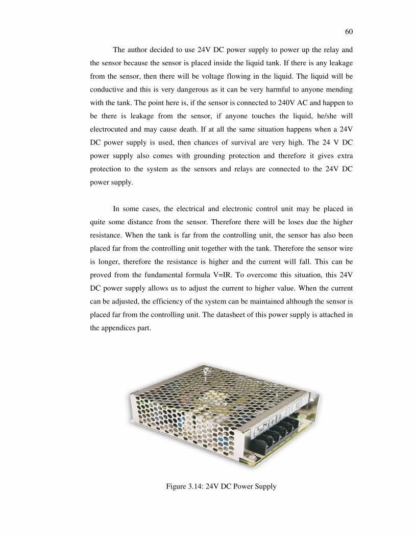
3. 24V DC Power Supply
This 24V DC power supply is used by the author to achieve the main objective of
this project which is to improve the safety features of this system and to reduce the
power consumption of this whole system.
Firstly to improve the safety features of this system, the author used this 24 V
DC to reduce the incoming 240V AC supply to 24 V DC. By doing so, the author can
connect the two 24V DC relays directly to this power supply to energize its coils. In
addition to this, the author has also connected the two magnetic level float switches
to this 24V DC power supply.
60
The author decided to use 24V DC power supply to power up the relay and
the sensor because the sensor is placed inside the liquid tank. If there is any leakage
from the sensor, then there will be voltage flowing in the liquid. The liquid will be
conductive and this is very dangerous as it can be very harmful to anyone mending
with the tank. The point here is, if the sensor is connected to 240V AC and happen to
be there is leakage from the sensor, if anyone touches the liquid, he/she will
electrocuted and may cause death. If at all the same situation happens when a 24V
DC power supply is used, then chances of survival are very high. The 24 V DC
power supply also comes with grounding protection and therefore it gives extra
protection to the system as the sensors and relays are connected to the 24V DC
power supply.
In some cases, the electrical and electronic control unit may be placed in
quite some distance from the sensor. Therefore there will be loses due the higher
resistance. When the tank is far from the controlling unit, the sensor has also been
placed far from the controlling unit together with the tank. Therefore the sensor wire
is longer, therefore the resistance is higher and the current will fall. This can be
proved from the fundamental formula V=IR. To overcome this situation, this 24V
DC power supply allows us to adjust the current to higher value. When the current
can be adjusted, the efficiency of the system can be maintained although the sensor is
placed far from the controlling unit. The datasheet of this power supply is attached in
the appendices part.
Figure 3.14: 24V DC Power Supply

61
4. Relay Socket for Omron Set/Reset Relay
This relay socket is to connect the relay at one side and the wires at the other side.
This socket with connectors around it numbered according to the reference of the
datasheet of this relay. So users have to refer to the datasheet of this relay and do the
wiring on the socket.
Figure 3.15: Omron Set/Reset Relay Socket
5. Relay Socket for Relpol 24V DC Relay
This socket as the same functions as the socket above. We refer to the datasheet of
this relpol relay and do the necessary wiring on the socket.
Figure 3.16: Relpol 24V DC Relay Socket
6. Earth Leakage Circuit Breaker (ELCB)
This ELCB was used by the author to protect the circuit in case of any fault. If
there’s any short circuit or voltage surge, this ELCB will trip and power supply to
this entire system will be interrupted. Therefore all the essential components in this

62
system like the sensor, 24V DC power supply, the relays and the pumps can be
protected.
Figure 3.17: ELCB
7. Isolator Switch
This isolator switch was used by the author in this system to switch on and off the
entire system. When the button is in OFF state, the entire system is switched off.
When the button is turned to manual mode, the entire system will be controlled
manually and where else when the button is set to the auto state, the entire system
will run automatically. This device will help users to detect any errors in the system.
Figure 3.18: Isolator Switch

63
8. Wire Terminal Block
This terminal block is like connectors. The author used this terminal block to connect
the two pumps and the two sensors.
Figure 3.19: Wire Terminal Block
9. PVC 310x230x145 Junction Box
This PVC 310x230x145 junction box was used by the author as casing to contain all
the electrical and electronic controlling unit components. This junction box was
screwed to the skid and the components were fixed inside the junction box.
Figure 3.20: PVC 310x230x145 Junction Box

64
Upon determining all the components needed, the author the connected all the
components according to the electrical diagram drawn. He wired up all the
components according to electrical diagram. The author also added marker to every
wire when doing the connection so that the author can trace back the wires in case
there is any errors or faults. The author used 1.5mm core red cables to wire all the
life points and 1.5mm core black wires to connect all the neutral points. The author
also used 1.5mm core green wire to connect all the earth points.
3.3.3 Repair and Fix the Two Pumps to the Skid
After completing the electrical and electronic controlling unit, the author then bought
two second hand pumps. The author then reconditioned the two pumps to be used in
this system.
One of the pumps was still working when it was bought. Therefore the author
just cleaned the electronic card of the pump and bought suction and discharge valves
to replace the worn out ones in the pump. The other pump needed some repair in its
electronic card. Its transformer, power switching IC and two power diodes were
spoiled, therefore the author replaced all the faulty components and then the pump
was working. The author also replaced its suction and discharge valves of the pump
as it was worn out as well.

65
Figure 3.21: The faulty electronic card of one of the pumps
After conducting the entire repair job, the author tested both the pumps. He
switched on both the pumps for two hours to test its efficiency. After testing, when
all was fine, the author screwed both the pumps onto the skid.
3.3.4 Connect the Magnetic Level Float Switch
After getting the pumps ready, then the author bought two magnetic level float
switches. Then he made a holder for the magnetic level float switch using a PVC
pipe. The author decided to use this type of level sensor because it is dry contact and
does not have any conducting parts. Therefore when the sensor is placed in the liquid,
it will not be dangerous to people who is handling with the liquid.
This type of sensor is very safe and can be used for any type of liquids. The
author did not use the conductivity type of sensor although the conductivity type has
higher precision because the conductivity type of sensor is very dangerous as it will
have voltage running in the liquid and eventually onto the tank as well if the tank is

66
made out of metal. The conductivity type of sensor can also cause explosion if there
is any flammable gas around the sensor.
After going thru all this carefully, the author decided to use the dry type of
level sensor which is magnetic level float switch. The datasheet of the magnetic level
float switch used is attached in the appendices part.
Figure 3.22: Magnetic Level Float Switch with Holder
After fixing the sensor to the holder, the author wired the sensor to the
electrical and electronic controlling unit.
3.3.5 Test Run the Whole System
After completing all the above steps, the author then designed a power cable for the
system. One end of the wire was fixed with 3-pin plug and at the other end of the
wire; the life and neutral wires were connected to the incoming supply of the ELCB.
The earth wire was connected to the terminal block which has all the earth wires and
later the terminal block was grounded.
Later the author connected the 3-pin plug to the power supply and powered
the entire system. The system was working according to what was expected. The
author switched the system on for 2 hours to test the workability of the system and to
test if there is any error.

67
CHAPTER 4
4 RESULTS AND DISCUSSIONS
4.1 General Discussion
The author has mentioned earlier that the main objectives of this project are to
enhance the protection of this tank switching system.
To achieve this objective, the author used a 24V DC power supply to power
the sensors and the relays attached to the sensors. By using the 24V DC power
supply, the sensor will only running in 24V DC instead of 240V AC. So if let say,
there is explosive gas around the tank and the sensor is worn out due to corrosion and
durability, there will be voltage leakage. This voltage leakage may cause arching
with the explosive gas. If the voltage is higher, the arching might be more dangerous
and may cause explosion. This can be prevented if the voltage used to power the
sensor is low.
If the voltage is higher and there is a leakage in the sensor, the voltage will be
flowing in the liquid of the tank and eventually on the tank. So if anyone touches the
tank, he/she will be electrocuted with a voltage of magnitude 240V AC, which is
extremely dangerous. Therefore, by using 24 V DC, the author can cultivate all this
undesirable events from occurring.
Although by using the 24V DC power supply the author can achieve this
objective, the author has to prove that the system’s efficiency is higher or the same as
using 240V AC to power the sensor. If the efficiency is the same or higher, then the

68
author have achieved the main objective of this project. Efficiency is the time taken
for the pump to switch over from one tank to the other tank and speed of the
transition upon sensor detection and relay switching.
Therefore to test the efficiency of this system, the author conducted two
experiments. In the first experiment, the author connected the two magnetic level
float switches and the two relays corresponding to the sensors to 240 V AC.
Therefore the author have to use 240V AC relay instead 24V DC relay. The sensor is
the same. The author then measured the time taken for the pump A to pump 0.2 liters
water and switch to pump B upon sensor A detecting a low level at different pump
speeds. He repeated the experiment for pump B to pump 1 liter water and switch to
pump A again upon sensor B detecting a low level.
The author then conducted the second experiment with the two magnetic
level float switches and the two relays connected to the 24 V DC power supply. In
this experiment for sure, the author used the 24V DC relay and the same sensor. He
then repeated the same steps in first experiment which is to measure the time taken
for pump A to pump 0.2 liters of water and switch to pump B upon sensor A detects
a low level. The experiment was repeated to measure the time taken for pump B to
pump 1 liter of water and switch over to pump A upon sensor B detects a low level.
4.2 Experiment 1 (Using 240V AC)
In experiment 1, the author connected the two magnetic level float switches and the
relay corresponding to the sensors to 240V AC power. The relay used is 240V AC
relay which has the same specification with the 24V DC relay. Both relays must have
the same specification as it will be very vital in producing the end result. The sensor
used is the same which is the magnetic level float switch.
In this experiment, for the first section, the author measured the time taken
for pump A to pump 0.2 liters of water and then switch over to pump B. The author
conducted this experiment for four different stroke length of the pump which is 25%,

69
50%, 75% and 100%. Stroke length of pump is defined as the distance marked by the
farthest ends of reciprocating vertical movement of the diaphragm.
For each stroke length, the author conducted five experiments with each of
the experiment with different frequencies. There are total five frequencies which are
60 Hz, 70 Hz, 80 Hz, 90 Hz and 100 Hz. Frequency here means is how fast the pump
diaphragm moves. For each experiment, five readings of time were measured and the
average is calculated and tabulated. The results obtained from these experiments
were tabulated in table below.
Table 4.1: Time taken by pump A to pump 0.2 liters of water and switch over to
pump B at stroke length of 25 %
Frequency
(Hz)
Time (Seconds)
1 2 3 4 5 Average
60 1049.0 1053.0 1055.0 1051.0 1050.0 1051.6
70 1020.0 1019.0 1025.0 1028.0 1027.0 1023.8
80 986.0 989.0 991.0 988.0 992.0 989.2
90 953.0 952.0 956.0 958.0 955.0 954.8
100 920.0 923.0 918.0 921.0 922.0 920.8
Table 4.2: Time taken by pump A to pump 0.2 liters of water and switch over to
pump B at stroke length of 50 %
Frequency
(Hz)
Time (Seconds)
1 2 3 4 5 Average
60 905.0 908.0 910.0 907.0 906.0 907.2
70 878.0 875.0 877.0 879.0 878.0 877.4
80 849.0 847.0 850.0 846.0 847.0 847.8
90 825.0 823.0 826.0 824.0 826.0 824.8
100 795.0 799.0 800.0 797.0 796.0 797.4

70
Table 4.3: Time taken by pump A to pump 0.2 liters of water and switch over to
pump B at stroke length of 75 %
Frequency
(Hz)
Time (Seconds)
1 2 3 4 5 Average
60 825.0 826.0 828.0 824.0 827.0 826.0
70 796.0 799.0 800.0 802.0 797.0 798.8
80 785.0 784.0 782.0 786.0 784.0 784.2
90 759.0 763.0 765.0 760.0 758.0 761.0
100 749.0 751.0 750.0 747.0 753.0 750.0
Table 4.4: Time taken by pump A to pump 0.2 liters of water and switch over to
pump B at stroke length of 100%
Frequency
(Hz)
Time (Seconds)
1 2 3 4 5 Average
60 758.0 755.0 759.0 762.0 760.0 758.8
70 743.0 748.0 745.0 744.0 745.0 745.0
80 728.0 733.0 729.0 730.0 735.0 731.0
90 679.0 683.0 689.0 687.0 691.0 685.8
100 664.0 670.0 661.0 665.0 668.0 665.6

71
Figure 4.1: Performance of the Tank Switching System Powered by 240V AC
measured in terms of Time taken by pump A to pump 0.2 liters of water and switch
over to pump B at four different stroke lengths
The data tabulated in the above tables were plotted into the graph above
whereby, the average of the five readings for the time was plotted against the
frequency for four different stroke lengths.
The above experiment then was repeated by the author again with now to
measure the time taken by pump B to pump 0.2 liters of water and then switch over
to pump A at four different stroke lengths and for each stroke length at five different
frequencies.

72
Table 4.5: Time taken by pump B to pump 0.2 liters of water and switch over to
pump A at stroke length of 25 %
Frequency
(Hz)
Time (Seconds)
1 2 3 4 5 Average
60 1047.0 1054.0 1050.0 1049.0 1054.0 1050.8
70 1018.0 1021.0 1026.0 1024.0 1025.0 1022.8
80 988.0 985.0 993.0 989.0 995.0 990.0
90 954.0 950.0 955.0 953.0 959.0 954.2
100 923.0 919.0 921.0 924.0 920.0 921.4
Table 4.6: Time taken by pump B to pump 0.2 liters of water and switch over to
pump A at stroke length of 50 %
Frequency
(Hz)
Time (Seconds)
1 2 3 4 5 Average
60 902.0 906.0 912.0 907.0 909.0 907.2
70 874.0 879.0 880.0 882.0 877.0 878.4
80 852.0 849.0 854.0 848.0 850.0 850.6
90 829.0 825.0 828.0 824.0 823.0 825.8
100 793.0 798.0 801.0 799.0 797.0 797.4
Table 4.7: Time taken by pump B to pump 0.2 liters of water and switch over to
pump A at stroke length of 75 %
Frequency
(Hz)
Time (Seconds)
1 2 3 4 5 Average
60 825.0 826.0 828.0 824.0 827.0 826.0
70 794.0 797.0 798.0 801.0 800.0 798.0
80 783.0 780.0 777.0 782.0 785.0 781.4
90 755.0 762.0 764.0 763.0 760.0 760.8
100 744.0 752.0 748.0 747.0 753.0 748.8

73
Table 4.8: Time taken by pump B to pump 0.2 liters of water and switch over to
pump A at stroke length of 100 %
Frequency
(Hz)
Time (Seconds)
1 2 3 4 5 Average
60 755.0 759.0 763.0 758.0 756.0 758.2
70 741.0 746.0 743.0 747.0 742.0 743.8
80 727.0 731.0 728.0 734.0 733.0 730.6
90 680.0 685.0 690.0 687.0 686.0 685.6
100 659.0 665.0 660.0 668.0 669.0 664.2
The data tabulated from the tables were put together in to the graph below to
see the performance of the tank switching system.
Figure 4.2: Performance of the Tank Switching System Powered by 240V AC
measured in terms of Time taken by pump B to pump 0.2 liters of water and switch
over to pump A at four different stroke lengths

74
4.3 Experiment 2 (Using 24V DC)
In experiment 2, the author connected the two magnetic level float switches and the
relay corresponding to the sensors to 24V DC power. The relay used is 24V DC relay
which has the same specification with the 240V AC relay used in the experiment 1.
Both relays must have the same specification as it will be very vital in producing the
end result. The sensor used is the same which is the magnetic level float switch.
In this experiment, for the first section, the author measured the time taken
for pump A to pump 0.2 liters of water and then switch over to pump B. The author
conducted this experiment for four different stroke length of the pump which is 25%,
50%, 75% and 100%. Stroke length of pump is defined as the distance marked by the
farthest ends of reciprocating vertical movement of the diaphragm.
For each stroke length, the author conducted five experiments with each of
the experiment with different frequencies. There are total five frequencies which are
60 Hz, 70 Hz, 80 Hz, 90 Hz and 100 Hz. Frequency here means is how fast the pump
diaphragm moves. For each experiment, five readings of time were measured and the
average is calculated and tabulated. The results obtained from these experiments
were tabulated in table below.
Table 4.9: Time taken by pump A to pump 0.2 liters of water and switch over to
pump B at stroke length of 25 %
Frequency
(Hz)
Time (Seconds)
1 2 3 4 5 Average
60 1048.0 1055.0 1047.0 1049.0 1052.0 1050.2
70 1022.0 1016.0 1023.0 1027.0 1030.0 1023.6
80 985.0 990.0 993.0 989.0 987.0 988.8
90 957.0 955.0 954.0 959.0 960.0 957.0
100 922.0 923.0 921.0 918.0 920.0 920.8

75
Table 4.10: Time taken by pump A to pump 0.2 liters of water and switch over
to pump B at stroke length of 50 %
Frequency
(Hz)
Time (Seconds)
1 2 3 4 5 Average
60 907.0 905.0 909.0 911.0 908.0 908.0
70 875.0 874.0 876.0 880.0 874.0 875.8
80 848.0 851.0 855.0 849.0 846.0 849.8
90 823.0 821.0 825.0 827.0 825.0 824.2
100 794.0 795.0 799.0 802.0 793.0 796.6
Table 4.11: Time taken by pump A to pump 0.2 liters of water and switch over
to pump B at stroke length of 75 %
Frequency
(Hz)
Time (Seconds)
1 2 3 4 5 Average
60 823.0 827.0 826.0 830.0 822.0 825.6
70 797.0 795.0 799.0 801.0 803.0 799.0
80 787.0 785.0 784.0 783.0 782.0 784.2
90 763.0 759.0 760.0 759.0 766.0 761.4
100 744.0 749.0 741.0 745.0 748.0 745.4
Table 4.12: Time taken by pump A to pump 0.2 liters of water and switch over
to pump B at stroke length of 100 %
Frequency
(Hz)
Time (Seconds)
1 2 3 4 5 Average
60 752.0 759.0 763.0 757.0 765.0 759.2
70 740.0 745.0 749.0 744.0 742.0 744.0
80 729.0 725.0 720.0 722.0 723.0 723.8
90 679.0 680.0 686.0 692.0 694.0 686.2
100 665.0 660.0 664.0 669.0 672.0 666.0

76
Figure 4.3: Performance of the Tank Switching System with 24 V DC Power Supply
measured in terms of Time taken by pump A to pump 0.2 liters of water and switch
over to pump B at four different stroke lengths
For this experiment 2, again the data tabulated for this part experiments were
plotted in a graph. The graph plotted was the time taken to pump 0.2 liters of water in
seconds against the frequency in Hertz.
The above experiments were done again by the author with now measuring
the time for pump B to pump 0.2 liters of water and switch over to pump A. All the
result collected from the experiment was tabulated in the tables below and the graph
to verify the performance of the tank switching system were plotted based on the
tabulated data.
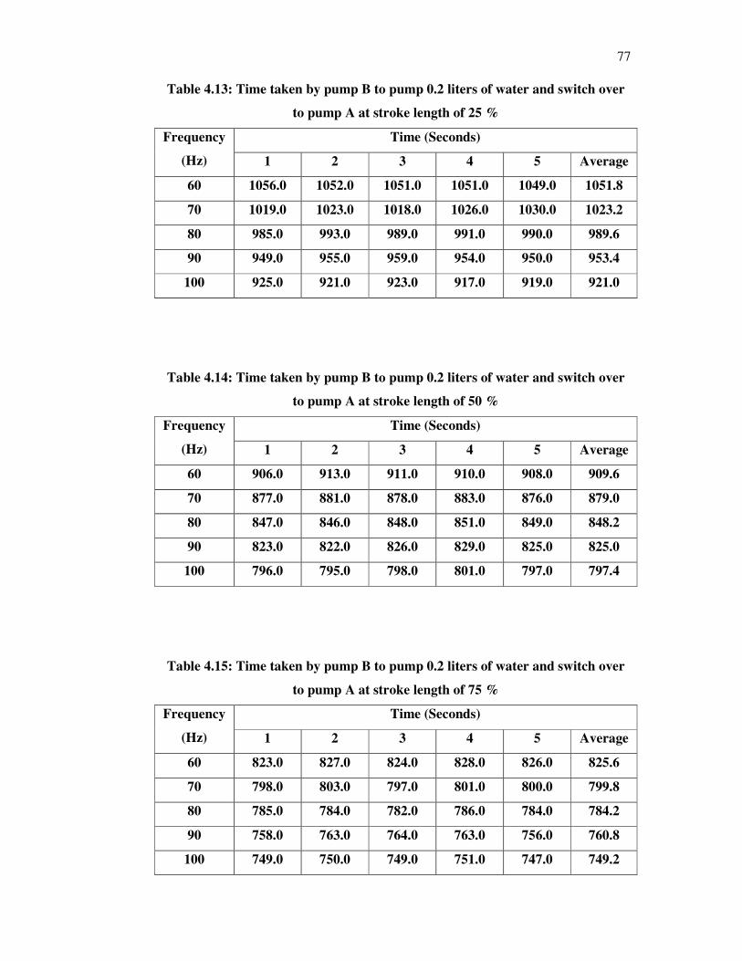
77
Table 4.13: Time taken by pump B to pump 0.2 liters of water and switch over
to pump A at stroke length of 25 %
Frequency
(Hz)
Time (Seconds)
1 2 3 4 5 Average
60 1056.0 1052.0 1051.0 1051.0 1049.0 1051.8
70 1019.0 1023.0 1018.0 1026.0 1030.0 1023.2
80 985.0 993.0 989.0 991.0 990.0 989.6
90 949.0 955.0 959.0 954.0 950.0 953.4
100 925.0 921.0 923.0 917.0 919.0 921.0
Table 4.14: Time taken by pump B to pump 0.2 liters of water and switch over
to pump A at stroke length of 50 %
Frequency
(Hz)
Time (Seconds)
1 2 3 4 5 Average
60 906.0 913.0 911.0 910.0 908.0 909.6
70 877.0 881.0 878.0 883.0 876.0 879.0
80 847.0 846.0 848.0 851.0 849.0 848.2
90 823.0 822.0 826.0 829.0 825.0 825.0
100 796.0 795.0 798.0 801.0 797.0 797.4
Table 4.15: Time taken by pump B to pump 0.2 liters of water and switch over
to pump A at stroke length of 75 %
Frequency
(Hz)
Time (Seconds)
1 2 3 4 5 Average
60 823.0 827.0 824.0 828.0 826.0 825.6
70 798.0 803.0 797.0 801.0 800.0 799.8
80 785.0 784.0 782.0 786.0 784.0 784.2
90 758.0 763.0 764.0 763.0 756.0 760.8
100 749.0 750.0 749.0 751.0 747.0 749.2

78
Table 4.16: Time taken by pump B to pump 0.2 liters of water and switch over
to pump A at stroke length of 100 %
Frequency
(Hz)
Time (Seconds)
1 2 3 4 5 Average
60 755.0 760.0 757.0 759.0 765.0 759.2
70 741.0 743.0 743.0 746.0 749.0 744.2
80 728.0 729.0 735.0 729.0 733.0 730.8
90 695.0 685.0 683.0 691.0 689.0 688.6
100 669.0 663.0 668.0 665.0 670.0 667.0
Figure 4.4: Performance of the Tank Switching System with 24 V DC Power Supply
measured in terms of Time taken by pump B to pump 0.2 liters of water and switch
over to pump A at four different stroke lengths

79
4.4 Overall Discussion
From the results tabulated above, the author without any doubt can conclude that the
usage of 24V DC power supply to power the magnetic level float switch sensor and
relays corresponding to the sensors have got the same efficiency as using 240V AC
to power the sensors and relays.
The reason why the author can say this because from the results tabulated
from the above experiments, can be seen that the average time taken for pump to
pump 0.2 liters of water is generally the same for both using 24V DC power supply
and 240 V AC power supply. From the graph plotted above, the trend for all four
conditions of the of the experiments is the same which is when stroke length is
smaller, the time taken is lower and when the frequency is lower, the time taken is
longer as well. This condition is satisfied for both 240 V AC and 24 V DC power
supplies.
From the results above, it can be seen that, for 240V AC, some of the average
time is longer compared to 24V DC for a given condition. For some of the condition,
it can be seen that the average time is lower for 240V AC compared to 24V DC. This
clearly indicates that, the use of 24 V DC power supply does not influence the
efficiency or the performance of the overall system.
The reason why both have got the same efficiency is because, the sensor is
using magnetic switch to operate, which means if 24V DC or 240V AC is supplied to
the sensor, it will still operate as usual, coz power is used by this sensor to energize
its coil in the sensor. When the float outside the insulated coil which has a magnet in
it is moved up and down, a pulse is sent to the relay. When the tank has water in it,
then the float will be up which indicates tank have got water. When the low level is
detected, which is when water in the tank finishes, the float will come down, which
will trigger the relay. Therefore the power is used for the sensor to energise its coil
only. So it doesn’t matter if 24V DC or 240V AC is used to energise its coil. This is
the reason why the efficiency is the same for both power supplies.

80
Another key thing to be noted is, when 24V DC is supplied to the sensor to
energise the coils, so automatically enhanced protection method have been achieved.
So if there is a leakage from the sensor due to corrosion or worn out, the leakage
voltage will only be 24V DC instead 240V AC if the sensor were to be powered with
240V AC. 24V DC has smaller impact on humans compared to 240V AC if at all
anyone to be electrocuted due to leakage.
The relays used also have no impact on the efficiency of this system because
both the relays, 24V DC and 240 V AC has got the same specification. Furthermore
power is used by this relay to energise it’s coil only, so if a 240V AC relay is used,
240 V AC is used to energise the coil of the relay and if 24V DC relay is used, then
24 V DC is used to energise the coil of the relay.
So after conducting all the experiments, the author can prove that the main
objective of this project which is to enhance the protection level of this water tank
switching system by using 24V DC power supply were achieved without affecting
the efficiency of the tank switching system.

81
CHAPTER 5
5 CONCLUSION AND RECOMMENDATIONS
5.1 Conclusion
As for the conclusion, the author can confidently conclude that the main objective of
this project has been achieved. The author has successfully found a method to
enhance the safety features of the tank switching system. This main objective of this
project was achieved by the author by using a 24 V DC power supply to power the
magnetic level float switch sensor and relay corresponding to the sensor.
The author has also mastered the working principle of relays and how to
utilise relays to do design a tank switching system. The author has also understood
thoroughly the working principle and main elements of pumps and sensors. There are
many types of pumps and sensors to be used in different types of environment and
surroundings. The author has mastered the usage of each type of pumps and sensors
and in which type of surroundings these pumps and sensors are used.
The author has also mastered the knowledge of repairing electronic cards by
repairing the electronic card of the pump and made the pump to be in a workable
condition again. This also shows that the author knows how electronics components
work and what the usage of the each electronic component is.

82
5.2 Future Recommendations
5.2.1 Have large capacity of storage tank
To have large capacity of storage tank, the system only requires a small alteration
which to design a larger version of storage tank. Other than storage tank, all other
equipments in this system would be still a same.
The users of this system can customize the type of storage tank that they
would like to have for their usage. Some customers may require to a very large
storing capacity of few hundred gallons of water and so on. So to have a large storing
capacity, the storage tank is customized in this system.
5.2.2 Have capability to pump more liquid
This enhancement can be achieved by changing the pump capacity. Other than
customizing the pump, the control elements of this system still remains the same.
The pump capacity is customized by choosing a pump which a have larger pumping
capacity like 50 liters per hour or 80 liters per house or pumps which even have
larger pumping capacity than this.
So when a large pump is used, then a large place may be required to fix this
system. A large area here means a wide area to have the bigger storage tank and
bigger capacity pump attached to it while the controlling unit is placed a little further
from the pump and storage tank so that the system is fixed neatly.
When the controlling unit is fixed in quite a distance from the pump and
storage tank, then wires connecting the sensor to the controlling unit will be longer.
From Ohms Law, V=IR, the loses will be higher due to the longer wire connection
which means longer wire connection have got higher resistance and therefore losses
would be high as well. Since the voltage is fixed at 24 V DC, the current got to be
increased. The 24V DC power supply the author has used in the electrical and

83
electronic controlling unit of this system provides the option to increase the current
level. Therefore by using a bigger capacity pump or large storage tank, the efficiency
of this tank switching system can still be maintained.
5.2.3 Have more precision of level measurement
This feature can be achieved in this system by replacing the magnetic level float
switch sensor with guided radar level sensor. Guided radar level sensor is widely
used in industries in this modern era due to its high precision.
This type of sensor has to be just attached to the top of the storage tank or the
cover of the storage tank. It sends waves to the bottom of the tank and when the tank
is empty, the sensor is triggered.
This type of sensor has higher efficiency compared to magnetic level float
switch because, when magnetic level float switch detects a low level, there will be
still a small amount of liquid in the tank. This is due to the structure of the magnetic
level float switch. Where else, for the guided radar level sensor, it will only be
triggered when the tank is totally empty. Besides that, the user can also actually set at
what level he wants the guided radar level sensor to be triggered rather than waiting
for the water to finish completely. The efficiency of this guided radar level sensor is
way higher compared to magnetic level float switch and yet the author did not use in
this project because due to budget constrain.
84
5.2.4 Have alarm to alert in tank is not filled up
This is another key feature that can be amended to this system. When first sensor is
detected to be low level, the pumping of liquid will switch from tank A to tank B. So
liquid will be pumped from tank B and someone has to fill up the liquid in tank A so
that when liquid in tank B drops below low level, and when sensor detects this, the
water can be pumped from tank A instead of tank B.
For an example, when the users of this tank forget to fill up the liquid in tank
A, and sensor in tank B also detects to be a low level, then the pump B will be
working but there will be no liquid to be pumped. So to alert users when this scenario
happens, the author recommends implementing an alarm system. When this specified
situation takes place, then the alarm will ring to alert the users to fill up both the
tanks.
85
REFERENCES
1. Babbit, Harrold, E., Donald, & James, J. (1962). Water Supply Engineering.
London: McGraw Hill
2. Endress & Hauser (2005). People for Process Optimization. Product
Catalogue
3. Karassik, J., Messina, J.P.,Cooper, P.H., & Charles, C. Pumps Hand book
(2001).Mc-Graw Hill
4. Siebe, B., Paul, K., & Rob,L. (1989). The Journal of Thermally Excited
Resonating Membrane Mass Flow Sensor. Sensors and Actuators, 213-223.
ISSN 0250-6874, DOI: 10.1016/0250-6874(89)801192
5. Industry Verlag GMB.(2007, Mei 4). The journal of Process Technology and
Automation, Volume 4.
6. Mitchel ,E. S.(2006). Grob’s Basic Electronics. McGraw-Hill/Higher
Education.
7. Meijers, Dr.A.P., COCODEV/IWSA-PERPAMSI International Water Supply
Association. Sedimentation and Flotation Workshop on Rehabilation and
Upgrading of Water Treatment Works.
8. Dictionary of Architecture and Construction (4th
Ed.).(2005). Cyril M. Harris,
The McGraw-Hill Companies, Inc.
9. Mitchel ,E. S.(2006). Grob’s Basic Electronics. McGraw-Hill/Higher
Education.

86
10. Ned, M., Tore, M. U., &William, R. (1995). Power Electronics:
Converters,Applications, and Design. John Wiley.
11. Hot-Dip Galvanized Pressed Steel Sectional Water Tank. (2011). Electronic
references. Retrieved Febreuary 4, 2011 from
http://www.yising.com.my/catalog/galvanized-pressed-steel-sectional-water-
tank-p-43.html
12. Fiberglass Storage Tanks.(2011). Electronic references. Retrieved March 2,
2011 from http://catalogs.indiamart.com/products/frp-tank.html
13. Fusion Glass Fused to Steel Tank.(2011). Electronic references. Retrieved
March 4, 2011 from http://www.watertanks.com/glassfusedtanks/
14. Settling. (2001). Electronic references. Retrieved March 12, 2011 from
http://nptel.iitm.ac.in/courses/Webcourse-contents/IIT-
KANPUR/wasteWater/Lecture%206.htm
15. Sekopumps.(2009). Electronic references. Retrieved March 13, 2011 from
www.sekopump.com.my
16. Rotary Gear Pump.(2011). Electronic references. Retrieved March 15, 2011
from
http://www.grpumps.com/types.asp?action=list&kind=Rotary%20Gear%20&
kid=29&level=types
17. Float Switch and Liquid Level Sensor Products.(2002). Electronic references.
Retrieved March 20, 2011 from http://www.fluidswitch.com/
18. Sensors. (2009). Electronic references. Retrieved March 25, 2011 from
http://www.abmsensor.com/
19. Measurement Products. (2011). Electronic references. Retrieved March 27,
2011 from http://www.abb.com/product/us/9AAC910019.aspx
87
20. Temperature sensors.(2009). Electronic references. Retrieved March 29, 2011
from http://www.biral.com/meteorological-sensors/temperature-radiation-
etc/temperature-sensor-compact-output-pt100
21. ELCB. (2011). Electronic references. Retrieved April 1, 2011 from
http://www.tnb.com.my/residential/your-safety/elcb.html
22. ELCB MCB. (2009). Electronic references. Retrieved April 3, 2011 from
http://etenaga.wordpress.com/2009/07/15/elcb-mcb/
23. John Hewes(2011). “Relays” Electronic references. Retrieved April 5, 2011
from http://www.kpsec.freeuk.com/components/relay.htm
24. Level Switches. (2011). Electronic references. Retrieved April 7, 2011 from
http://www.nivelco.com/site.php?upar=PRODUCT&lang=en

88
APPENDICES
APPENDIX A: Data Sheet of the 24 V DC power supply

89

90

91
APPENDIX B: Data Sheet of the 24 V DC Relpol relay

92

93

94

95

96

97
APPENDIX C: Data Sheet of the 240 V AC Omron relay

98

99

100
APPENDIX D: Data Sheet of the magnetic level float switch sensor

101

102