DESIGN A HIGH PERFORMANCE ABSORBER TO IMPROVE … A HIGH PERFORMANCE ABSORBER TO...penyerap...
24
DESIGN A HIGH PERFORMANCE ABSORBER TO IMPROVE AN ANECHOIC CHAMBER PERFORMANCE Chai Chok Hung Bachelor of Engineering with Honors (Electronics & Telecommunications Engineering) 2009/2010
Transcript of DESIGN A HIGH PERFORMANCE ABSORBER TO IMPROVE … A HIGH PERFORMANCE ABSORBER TO...penyerap...
DESIGN A HIGH PERFORMANCE ABSORBER TO IMPROVE AN
ANECHOIC CHAMBER PERFORMANCE
Chai Chok Hung
Bachelor of Engineering with Honors
(Electronics & Telecommunications Engineering)
2009/2010

UNIVERSITI MALAYSIA SARAWAK
R13a
BORANG PENGESAHAN STATUS TESIS
Judul: DESIGN A HIGH PERFORMANCE ABSORBER TO IMPROVE AN ANECHOIC
CHAMBER PERFORMANCE
SESI PENGAJIAN: 2009/2010
Saya CHAI CHOK HUNG
(HURUF BESAR)
mengaku membenarkan tesis * ini disimpan di Pusat Khidmat Maklumat Akademik, Universiti Malaysia Sarawak
dengan syarat-syarat kegunaan seperti berikut:
1. Tesis adalah hakmilik Universiti Malaysia Sarawak.
2. Pusat Khidmat Maklumat Akademik, Universiti Malaysia Sarawak dibenarkan membuat salinan untuk
tujuan pengajian sahaja.
3. Membuat pendigitan untuk membangunkan Pangkalan Data Kandungan Tempatan.
4. Pusat Khidmat Maklumat Akademik, Universiti Malaysia Sarawak dibenarkan membuat salinan tesis ini
sebagai bahan pertukaran antara institusi pengajian tinggi.
5. ** Sila tandakan ( ) di kotak yang berkenaan
SULIT (Mengandungi maklumat yang berdarjah keselamatan atau kepentingan
Malaysia seperti yang termaktub di dalam AKTA RAHSIA RASMI 1972).
TERHAD (Mengandungi maklumat TERHAD yang telah ditentukan oleh organisasi/
badan di mana penyelidikan dijalankan).
TIDAK TERHAD
Disahkan oleh
(TANDATANGAN PENULIS) (TANDATANGAN PENYELIA)
Alamat tetap: LOT 1233, BATU 2, JALAN
ROCK, 93200 ,KUCHING ,SARAWAK.
DR. THELAHA HJ. MASRI
Nama Penyelia
Tarikh: 12 APRIL 2010 Tarikh:
CATATAN * Tesis dimaksudkan sebagai tesis bagi Ijazah Doktor Falsafah, Sarjana dan Sarjana Muda.
** Jika tesis ini SULIT atau TERHAD, sila lampirkan surat daripada pihak berkuasa/organisasi
berkenaan dengan menyatakan sekali sebab dan tempoh tesis ini perlu dikelaskan sebagai
SULIT dan TERHAD.
This Final Year Project attached here:
Title : DESIGN A HIGH PERFORMANCE ABSORBER TO
IMPROVE AN ANECHOIC CHAMBER PERFORMANCE
Student Name : Chai Chok Hung
Matric No : 17681
has been read and approved by:
__________________________ ______________________
Dr. Thelaha Hj. Masri Date
(Supervisor)

DESIGN A HIGH PERFORMANCE ABSORBER TO IMPROVE AN ANECHOIC
CHAMBER PEFORMANCE
CHAI CHOK HUNG
This project is submitted in partial fulfilment of
The requirements for the degree of Bachelor of Engineering with Honours
(Electronics and Telecommunications Engineering)
Faculty of Engineering
UNIVERSITI MALAYSIA SARAWAK
2009/2010

ii
Dedicated to my dearest friends and family

iii
ACKNOWLEDGEMENT
This project has been made possible as a result of the co-operation and support
rendered by several individuals. While it is impossible to list down all of them and I am
very grateful for their assistance.
Firstly, I would like to take this opportunity to express my deepest gratitude to my
Final Year Project supervisor, Dr. Thelaha Hj Masri from Faculty of Electronics
Engineering, Universiti Malaysia Sarawak (UNIMAS). I am thankful to his patience,
advices, comments and guidance towards completing this project. Without Dr. Thelaha’s
assistance, this project would not be possible.
I would like to express my greatest thankfulness to Miss Kasumawati Binti Lias as
my second supervisor who has given advice and suggestion throughout the completion
of this project. Besides, I would also like to express my sincere thanks to Mr. Yusmizan
Bin Hanin, Mr. Lawrence Sinin, Mr. Johari Karim, Mr. Iskaendasah Bin Minggu, Miss
Zuraida, and Mr. Azizan bin Segri, technicians of Electronics Engineering Faculty of
UNIMAS, to all my friends, my family for all their love, care, support and companion
that had helped me in sailing through the many hard days in lives and studies all these
while.
iv
ABSTRAK
Projek ini memperkenalkan cara menghasilkan penyerap gelombang mikro yang
berharga rendah, berkeupayaan tinggi dan mempunyai prestasi yang baik untuk
digunakan pada ruang tanpa gema atau lebih di kenali sebagai “Anechoic Chamber”.
Penyerap gelombang mikro yang dihasilkan akan digunakan pada julat frekuensi 3GHz
ke 15GHz. Banyak kaedah dan cara telah dikaji ke atas keupayaan penyerapan
gelombang mikro pada penyerap ini. Penyerap gelombang mikro ini diperbuat
menggunakan polistrene di mana ia di potong dalam bentuk piramid. Untuk meningkat
pretasi penyerap ini, serbuk arang telah dicampurkan dengan cat air. Sebelum model
penyerap gelombang mikro ini dibuat, pada mulanya direkacipta dan disimulasi dengan
menggunakan perisian “Computer Simulation Technology” di mana pretasi dan
keupayaannya dikaji. Akhir sekali, keputusan pretasi penyerap buatan ini dibandingkan
dengan penyerap gelombang komersil yang terdapat di Makmal Antenna, Fakulti
Kejuruteraan UNIMAS. Penyerap yang telah dihasilkan diberi nama penyerap
gelombang mikro kos rendah. Ciri utama penyerap gelombang mikro ini adalah kadar
penyerapan yang tinggi terhadap gelombang mikro dan mudah difabrikasi dengan kos
yang rendah.
v
ABSTRACT
This project presents the design of low cost, reliable and good performance
microwave absorber for application in anechoic chamber. The absorber is designed to be
functioning at frequency range from 3GHz to 15GHz. Different methods were
investigated in term of signal absorption of the absorber. The absorbers are made from
polystyrene, which were cut into pyramidal shape. The absorber is coated with charcoal
mixed with water based paint where it can increase the absorption capability of the
absorber. Before the real absorbers are fabricated, the absorber is first designed and
simulated using Computer Simulation Technology software to monitor their
performances. The measurement of the pyramidal absorber was done to determine its
performance. Lastly, the results are compared with commercialized absorber available in
the Antenna’s Laboratory of Faculty of Engineering, UNIMAS. The absorber that has
been developed is called low cost absorber. The major feature of the anechoic chamber
absorber in this project is high absorptions rate of microwave signal and easy to be
fabricated using low cost materials.

vi
TABLE OF CONTENTS
CONTENT PAGE
Dedication ii
Acknowledgement iii
Abstrak iv
Abstract v
Table of Contents vi
List of Tables x
List of Figures xi
List of Abbreviation xiii
CHAPTER 1 INTRODUCTION
1.1 Introduction 1
1.2 Objective 3
1.3 Scope of works 4
1.4 Project Outline 5
CHAPTER 2 LITERATURE REVIEW
2.1 Introduction 6
2.2 Anechoic Chamber 6
vii
2.3 Anechoic Chamber Design 7
2.3.1 Near-field Anechoic Chamber Design 7
2.4 Anechoic Chamber Enclosure 8
2.5 Electromagnetic Shielding Of Anechoic Chamber 8
2.5.1 Welded Shield 9
2.5.2 Clamped Seam or Prefabricated Shield 9
2.5.3 Single Shield System 10
2.6 Absorber 10
2.6.1 Understanding Absorber 11
2.6.2 Pyramidal Absorber Characteristics 13
2.7 Microwave Properties for Absorbing Material 14
2.8 Basic Component of Microwave Absorber 15
2.8.1 Matrixes for Microwave Absorber 15
2.8.1.1 Elastomer 16
2.8.1.2 Natural Rubber 16
2.8.1.3 Neoprene 16
2.8.1.4 Rubber 17
2.8.1.5 Resin 17
2.8.1.6 Foam and Honey Comb 18
2.8.2 Filler for Microwave Absorber 18
2.8.2.1 Ferrite 19
2.8.2.2 Carbon 19
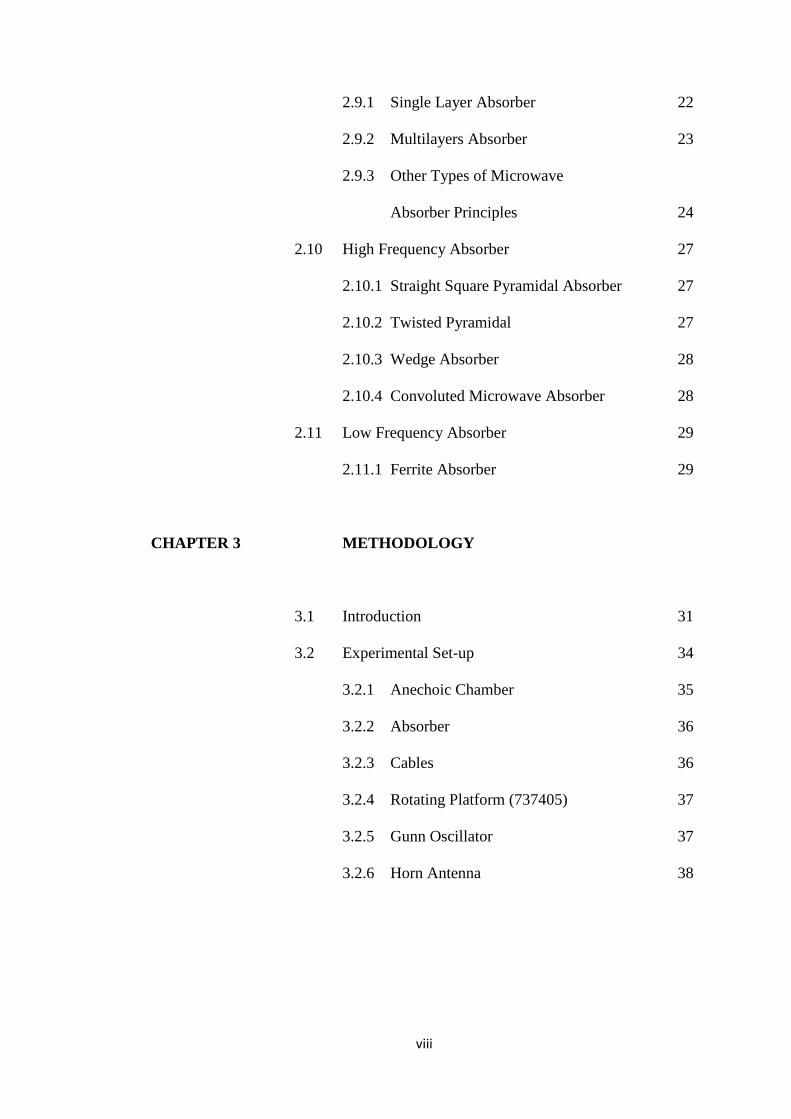
2.9 Principles of Microwave Absorber Operation 22
viii
2.9.1 Single Layer Absorber 22
2.9.2 Multilayers Absorber 23
2.9.3 Other Types of Microwave
Absorber Principles 24
2.10 High Frequency Absorber 27
2.10.1 Straight Square Pyramidal Absorber 27
2.10.2 Twisted Pyramidal 27
2.10.3 Wedge Absorber 28
2.10.4 Convoluted Microwave Absorber 28
2.11 Low Frequency Absorber 29
2.11.1 Ferrite Absorber 29
CHAPTER 3 METHODOLOGY
3.1 Introduction 31
3.2 Experimental Set-up 34
3.2.1 Anechoic Chamber 35
3.2.2 Absorber 36
3.2.3 Cables 36
3.2.4 Rotating Platform (737405) 37
3.2.5 Gunn Oscillator 37
3.2.6 Horn Antenna 38
ix
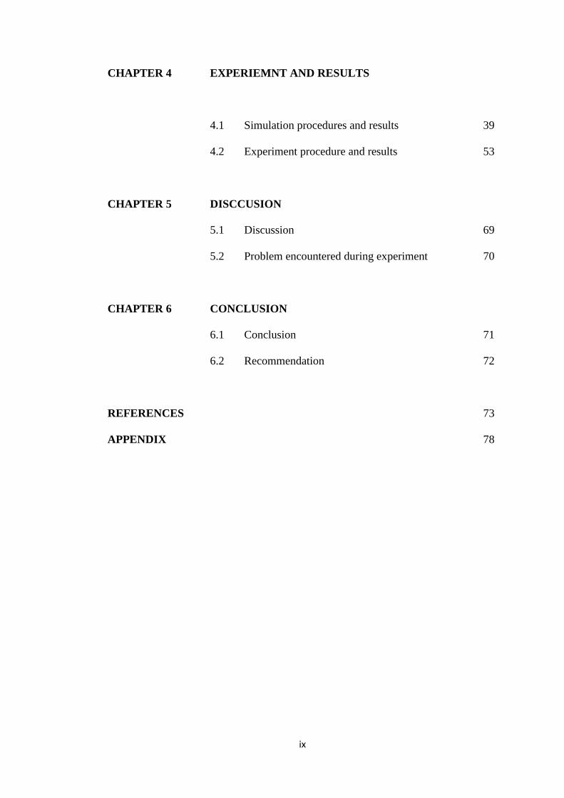
CHAPTER 4 EXPERIEMNT AND RESULTS
4.1 Simulation procedures and results 39
4.2 Experiment procedure and results 53
CHAPTER 5 DISCCUSION
5.1 Discussion 69
5.2 Problem encountered during experiment 70
CHAPTER 6 CONCLUSION
6.1 Conclusion 71
6.2 Recommendation 72
REFERENCES 73
APPENDIX 78
x
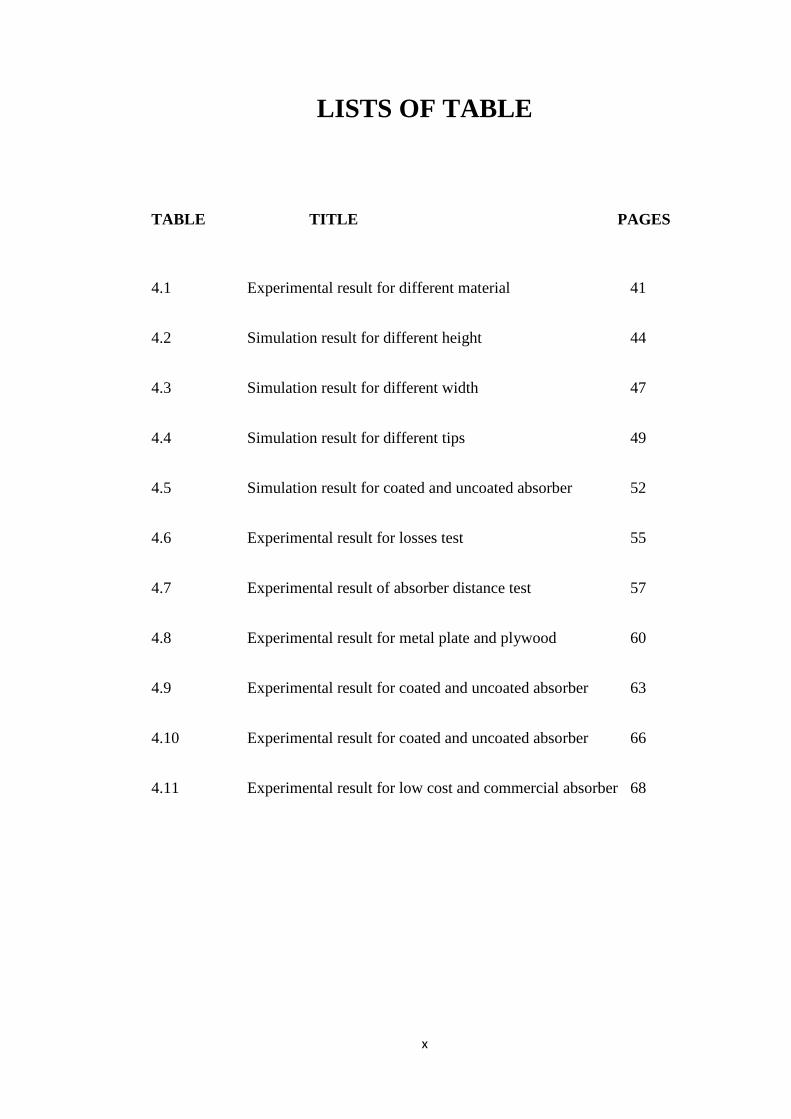
LISTS OF TABLE
TABLE TITLE PAGES
4.1 Experimental result for different material 41
4.2 Simulation result for different height 44
4.3 Simulation result for different width 47
4.4 Simulation result for different tips 49
4.5 Simulation result for coated and uncoated absorber 52
4.6 Experimental result for losses test 55
4.7 Experimental result of absorber distance test 57
4.8 Experimental result for metal plate and plywood 60
4.9 Experimental result for coated and uncoated absorber 63
4.10 Experimental result for coated and uncoated absorber 66
4.11 Experimental result for low cost and commercial absorber 68

xi
LISTS OF FIGURES
FIGURE TITLE PAGES
2.1 Reflected signal from pyramidal absorber wall 11
at nominal incidence
2.2 Reflected and Diffracted signal from pyramidal 12
wall absorber at oblique incidence
2.3 Reflected signal from a wedge absorber wall at 13
oblique incidence
2.4 Dimension of absorber 13
2.5 Single layer absorber (Salisbury Screen) 23
2.6 Multiple layer absorber (Jaumann layer) 24
2.7 Dallenbach layer 25
2.8 Pyramidal Absorber 27
2.9 Wedge Absorber 28
2.10 Convoluted Microwave absorber 29
2.11 Ferrite Absorber 30
2.12 Hybrid Absorber 30
3.1 Project Flow Chart 33
3.2 Measurement Setup 34
3.3 General Anechoic Chamber 35
3.4 Gunn Oscillator 37
3.5 Sketch of Horn Antenna 38
4.1 Absorber Parameter 39
xii
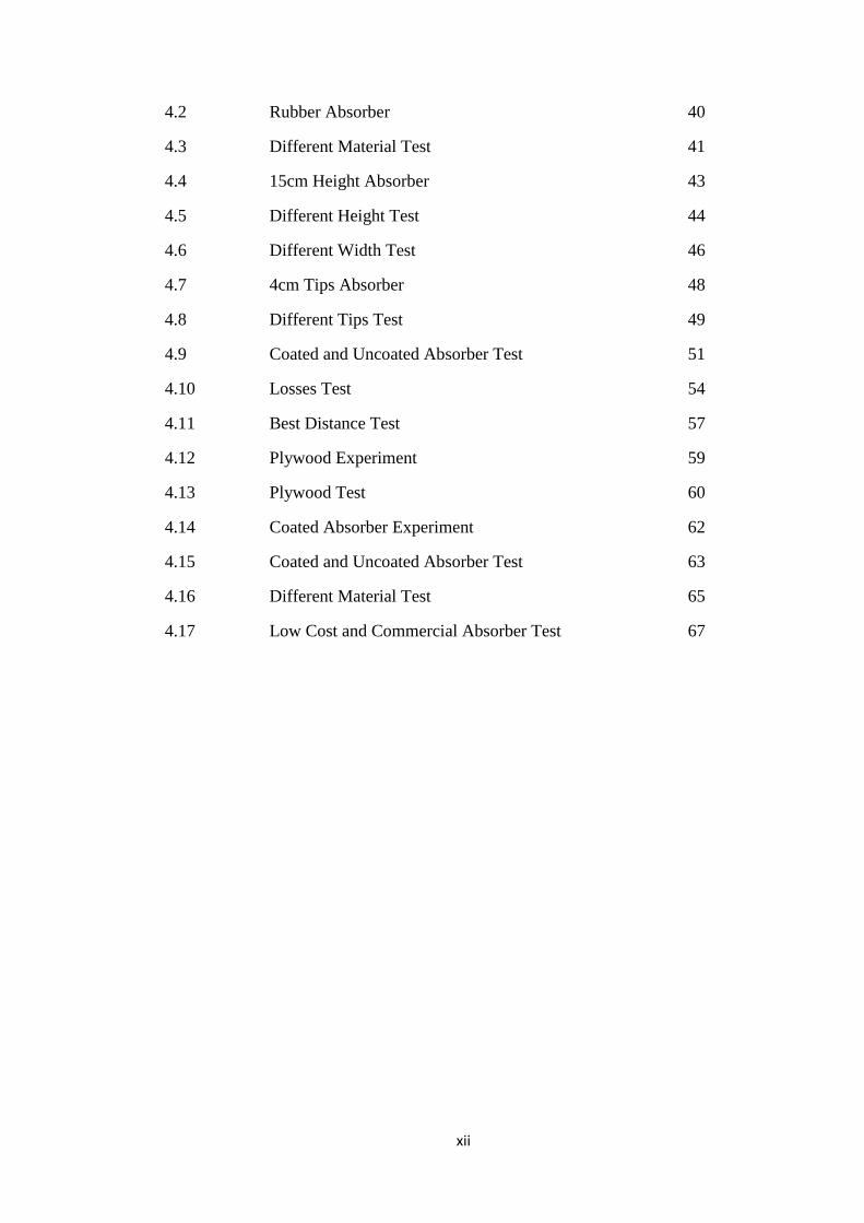
4.2 Rubber Absorber 40
4.3 Different Material Test 41
4.4 15cm Height Absorber 43
4.5 Different Height Test 44
4.6 Different Width Test 46
4.7 4cm Tips Absorber 48
4.8 Different Tips Test 49
4.9 Coated and Uncoated Absorber Test 51
4.10 Losses Test 54
4.11 Best Distance Test 57
4.12 Plywood Experiment 59
4.13 Plywood Test 60
4.14 Coated Absorber Experiment 62
4.15 Coated and Uncoated Absorber Test 63
4.16 Different Material Test 65
4.17 Low Cost and Commercial Absorber Test 67
xiii
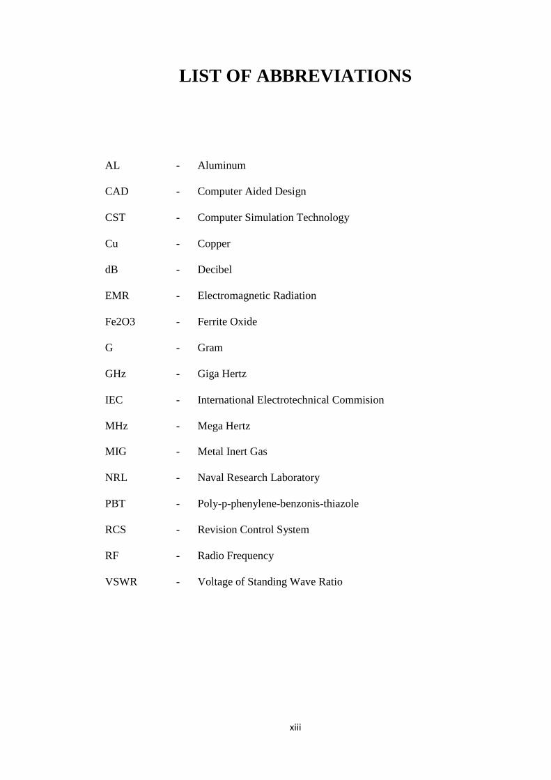
LIST OF ABBREVIATIONS
AL - Aluminum
CAD - Computer Aided Design
CST - Computer Simulation Technology
Cu - Copper
dB - Decibel
EMR - Electromagnetic Radiation
Fe2O3 - Ferrite Oxide
G - Gram
GHz - Giga Hertz
IEC - International Electrotechnical Commision
MHz
MIG
-
-
Mega Hertz
Metal Inert Gas
NRL - Naval Research Laboratory
PBT - Poly-p-phenylene-benzonis-thiazole
RCS - Revision Control System
RF - Radio Frequency
VSWR - Voltage of Standing Wave Ratio

1
CHAPTER 1
INTRODUCTION
1.1 Introduction
Mobile telecommunication market is one of the most rapid growing markets
around the world. Mobile telecommunication has makes the life of the society much
easier and faster. For example mobile phone can get a person in touch wherever that
person is as long as there is coverage. Nevertheless, for mobile telecommunications
system, there are weakness of their own such as the reflection, distortion and
scatterings which come from the environment.
Nowadays, telecommunication devices become more complex and need a high
frequency in transferring the information. The instruments such as the antenna need
to be tested without being affected by the wave reflection [1]. To get a best
performance of a telecommunication system, it is better to have an antenna that is
working perfectly. Before a good antenna can be manufactured, it must be tested for
their performances. The antenna performance is best to be tested in a space which is
isolated and the performance of the antenna is not influence by any of the internal
reflection or external interference. Antenna measurements are extensively conducted
2
throughout industry and government test facility. Thus the most suitable place for
this testing is the anechoic chamber.
An anechoic chamber is a shielded room designed to attenuate sound or
electromagnetic energy. Anechoic chambers were originally used in the context of
absorbing acoustic (sound) echoes caused by internal reflections of a room, but more
recently anechoic chambers have also been used to provide a shielded environment
for radio frequency (RF) and microwaves. Anechoic chambers range from small
compartments to ones as large as aircraft hangars [2]. The size of an anechoic
chamber depends on the size of the objects to be tested and the frequency range of
the radio or microwave signals used. Anechoic chamber is also used in aerospace
industry where missiles, aircraft or similar weapon platform are tested for their radar
cross section [3].
There are a few type of anechoic chamber such as, acoustic anechoic chambers,
semi-anechoic chambers, radio-frequency anechoic chambers and etc. For the
anechoic chamber to work effectively, all internal surfaces of the anechoic chamber
such as the back wall, the side-wall, the floor and corner of the chamber must be
entirely covered with radiation absorbent material which is also known as absorber.
Usually, in sound testing, porous and fibrous materials are used which are composed
of many fibers or cells, for example glass or mineral-wool, cocos fiber, felt, wood-
shaving or porous cellular foam [4].
Two most common absorbing materials that normally are used in
electromagnetic wave are the dielectric absorber and the ferrite absorber. They are
3
used in microwave frequency range and lower frequency range respectively [1]. This
project focused on the absorbing characteristics of the absorber. The absorber will be
tested with different height, width, and tips. Carbon acts as a lossy material
absorbing electromagnetic radiation (EMR) [2]. Before the absorber design and
testing is conducted, the absorber is first design using Computer Simulation
Technology (CST) software and the characteristic will be analyzed.
Absorbers are design using expanded polystyrene. Expanded polystyrene is a
kind of plastic which is made of normally white expanded beads. This polystyrene is
very useful in our life such as for protecting the fragile item. This type of polystyrene
can be easily obtained from the market and the price is affordable. After the absorber
is design in the desired shape and size, it will be painted with the mixture of charcoal
and water based paint.
1.2 Objective
The main objective of this project is to produce a simple, cheap and easy to
fabricate polystyrene absorber, analyzed with the effect of different height, width,
tips and several materials that are to be added to the absorber within the frequency
range of 3GHz to 15GHz.
To achieve this objective, there are many procedures and works that will be
taken into consideration such as:
4
1.3 Scope of works
I. Understand the different type of absorber that is used.
II. Design the model that is used for the experiment with the absorber that
has different dimension parameter, and material that is mixed.
III. Collect data and info of the absorber and the hazard that is concerning.
IV. Learn some basic knowledge of mobile communication concept.
V. Design the testing area for the experiment to be conducted.
VI. Discuss the best dimension parameter of an absorber.
To perform the experiment, computer, transmitting and receiving antenna, and
appropriate absorber will be used. In the experiment, the absorber is supposed to
absorb as much as possible the signal energy that is transmitted. Roughly the stage in
this experiment is mentioned bellow:
I. Design models using CST with different type of material.
II. Measure the signal absorption of the model with different dimensions
parameter.
III. Collect and discuss the result.
IV. Graph will be plotted and analyzed.
V. Result will be analyzed and compared with other researchers findings.

5
1.4 Project Outline
Chapters 1 give an overview of the project and the objective of the project. Chapter 2
consist of the literature review where it cover the scenario involved in mobile
communication especially signal propagation and absorbing properties of the
absorber. This chapter also includes the fundamental of absorber material such as
polystyrene that are coated and mix with other material together with plywood. This
chapter provides the knowledge about absorbing materials that are used and its
characteristics towards signal absorption, where the designed parameters of the
absorber are also discussed. Chapter 3 discussed the methodology of the project.
Experiment and result are explained in Chapter 4. Chapter 5 includes discussions and
Chapter 6 covers the conclusion and recommendation after conducting this project.

6
CHAPTER 2
LITERATURE RIVIEW
2.1 Introduction
This chapter describes a study on several types of chamber, absorber and type
according to the purpose of the facility and frequency of operation. Each different
type of chamber will use different type of absorber in order to develop a
comprehensive absorption of the signal. Two most common type of absorber are the
dielectric absorber used in microwave frequency and the ferrite absorber used in the
lower frequency range. After working on these of chamber and absorber, many
method and ideas raised.
2.2 Anechoic Chamber
“Anechoic chamber” is a place where the whole room has been covered with
material that scatters or absorbs much of incident energy in such a way that it can
stimulate free space environment. Its origin can be traced to efforts that build aircraft
which absorb or scatter radar signal during Second World War [5]. Shielded
7
anechoic chamber are widely used to provide RF isolated test region to stimulate
free-space test environment for measuring antenna. Anechoic chamber provide a
controlled environment which is not influence by weather and ambient condition.
Anechoic chamber are widely used to measure antennas from various
telecommunication links, remote sensing and radar signature [6].
2.3 Anechoic Chamber Design
The design of microwave anechoic chamber began drastically in 1950s. The
commercial high performance anechoic absorber became available in 1960s after the
concept of microwave anechoic chamber become more practical. In the 1980s, new
class of chamber has evolved [1].
2.3.1 Near-field Anechoic Chamber Design
The most important consideration in near-field anechoic chamber is to ensure
that the radiating aperture is fully terminated. In other words, the main beam of the
antenna must see a load termination of sufficient attenuation that the energy reflected
is very much lower with respect to the directed energy [1]. Although there is some
other extraneous energy, sampling method must remain.
8
2.4 Anechoic Chamber Enclosure
The purpose of shielding is to prevent interference and electronic
eavesdropping. Type of shielding is depending on the purpose or type of the
equipment that are used. For anechoic chamber, moderate shielding would be enough
to control the electromagnetic environment. In some other application, high
performance shielding is required to protect sensitive equipment from interference.
There are a few types of commonly used shielding material such as [1]:
I. Plywood/particleboard panels, copper foil or screen are laminated on one
or both sides with various grades of galvanized sheet metal are commonly
used for prefabricated enclosure.
II. Metal sheet of various thickness are welded into place on a steel
supporting structure.
III. Copper screening mounted to spot soldered and wooden studs.
IV. Contact adhesive is installed with aluminum foil, or moisture-proof
sheetrock, which has aluminum foil bonded to one face of the board.
V. Plywood is mounted with galvanized sheet metal that become single-
shielded system.
2.5 Electromagnetic Shielding Of Anechoic Chamber
The purpose of shielding the chamber is to prevent outside interference that
would disturb the measurement accuracy. There are three types of shielding such as