Desiccant cooling air conditioning: a review - · PDF fileDesiccant cooling air conditioning:...
23
Desiccant cooling air conditioning: a review K. Daou, R.Z. Wang * , Z.Z. Xia School of Mechanical Engineering, Institute of Refrigeration and Cryogenics, Shanghai Jiao Tong University, Shanghai 200030, China Received 22 June 2004; accepted 17 September 2004 Abstract In this paper, the principles underlying the operation of desiccant cooling systems are recalled and their actual technological applications are discussed. Through a literature review, the feasibility of the desiccant cooling in different climates is proven and the advantages it can offer in terms energy and cost savings are underscored. Some commented examples are presented to illustrate how the desiccant cooling can be a perfective supplement to other cooling systems such as traditional vapour compression air conditioning system, the evaporative cooling, and the chilled-ceiling radiant cooling. It is notably shown that the desiccant materials, when associated with evaporative cooling or chilled-ceiling radiant cooling, can render them applicable under a diversity of climatic conditions. q 2005 Elsevier Ltd. All rights reserved. Keywords: Technological applications; Desiccant wheel; Sensible heat ratio Contents 1. Introduction ......................................................... 57 2. Principles of desiccant cooling ........................................... 58 2.1. The desiccant dehumidifier .......................................... 58 2.2. The cooling unit .................................................. 59 2.3. The regeneration heat source ........................................ 59 3. Literature survey ..................................................... 60 3.1. Feasibility studies ................................................. 60 1364-0321/$ - see front matter q 2005 Elsevier Ltd. All rights reserved. doi:10.1016/j.rser.2004.09.010 Renewable and Sustainable Energy Reviews 10 (2006) 55–77 www.elsevier.com/locate/rser * Corresponding author. Tel.: C86 21 62933838; fax: C86 21 62933250. E-mail address: [email protected] (R.Z. Wang).
Transcript of Desiccant cooling air conditioning: a review - · PDF fileDesiccant cooling air conditioning:...
Desiccant cooling air conditioning: a review
K. Daou, R.Z. Wang*, Z.Z. Xia
School of Mechanical Engineering, Institute of Refrigeration and Cryogenics,
Shanghai Jiao Tong University, Shanghai 200030, China
Received 22 June 2004; accepted 17 September 2004
Abstract
In this paper, the principles underlying the operation of desiccant cooling systems are recalled and
their actual technological applications are discussed. Through a literature review, the feasibility of
the desiccant cooling in different climates is proven and the advantages it can offer in terms energy
and cost savings are underscored. Some commented examples are presented to illustrate how the
desiccant cooling can be a perfective supplement to other cooling systems such as traditional vapour
compression air conditioning system, the evaporative cooling, and the chilled-ceiling radiant
cooling. It is notably shown that the desiccant materials, when associated with evaporative cooling or
chilled-ceiling radiant cooling, can render them applicable under a diversity of climatic conditions.
q 2005 Elsevier Ltd. All rights reserved.
Keywords: Technological applications; Desiccant wheel; Sensible heat ratio
Contents
1. Introduction . . . . . . . . . . . . . . . . . . . . . . . . . . . . . . . . . . . . . . . . . . . . . . . . . . . . . . . . . 57
2. Principles of desiccant cooling . . . . . . . . . . . . . . . . . . . . . . . . . . . . . . . . . . . . . . . . . . . 58
2.1. The desiccant dehumidifier . . . . . . . . . . . . . . . . . . . . . . . . . . . . . . . . . . . . . . . . . . 58
2.2. The cooling unit . . . . . . . . . . . . . . . . . . . . . . . . . . . . . . . . . . . . . . . . . . . . . . . . . . 59
2.3. The regeneration heat source . . . . . . . . . . . . . . . . . . . . . . . . . . . . . . . . . . . . . . . . 59
3. Literature survey . . . . . . . . . . . . . . . . . . . . . . . . . . . . . . . . . . . . . . . . . . . . . . . . . . . . . 60
3.1. Feasibility studies . . . . . . . . . . . . . . . . . . . . . . . . . . . . . . . . . . . . . . . . . . . . . . . . . 60
Renewable and Sustainable Energy Reviews
10 (2006) 55–77
www.elsevier.com/locate/rser
1364-0321/$ - see front matter q 2005 Elsevier Ltd. All rights reserved.
doi:10.1016/j.rser.2004.09.010
* Corresponding author. Tel.: C86 21 62933838; fax: C86 21 62933250.
E-mail address: [email protected] (R.Z. Wang).

Nomenclature
P Vapour pressure [Pa]
C Heat capacity rate [kW/K]
G Mass flow rate per unit cross-sectional area [kg/m2 s]
T Temperature [K]
3 Adsorption potential energy [J], Effectiveness
_ma Mass flow rate of process air [kg/s]
_mv Rate of water adsorbed from the processed air by the desiccant [g/s]
x Concentration of desiccant solution [kg/m3]
SHR Sensible heat ratio
Subscript
i Inlet
o Outlet
DW Desiccant wheel
RHW Rotary heat wheel
S Desiccant Solution
wb Wet bulb
c Cooling medium
HE Heat exchange
m Moisture
a Air
L Liquid desiccant
K. Daou et al. / Renewable and Sustainable Energy Reviews 10 (2006) 55–7756
3.2. Performance studies . . . . . . . . . . . . . . . . . . . . . . . . . . . . . . . . . . . . . . . . . . . . . . . 61
3.3. Desiccant material studies . . . . . . . . . . . . . . . . . . . . . . . . . . . . . . . . . . . . . . . . . . 62
3.4. Use of desiccant cooling for preservation purpose . . . . . . . . . . . . . . . . . . . . . . . . . 63
4. Commented examples of desiccant cooling . . . . . . . . . . . . . . . . . . . . . . . . . . . . . . . . . . 63
4.1. Solid desiccant cooling . . . . . . . . . . . . . . . . . . . . . . . . . . . . . . . . . . . . . . . . . . . . . 63
4.1.1. Evaporative cooling . . . . . . . . . . . . . . . . . . . . . . . . . . . . . . . . . . . . . . . . . . 63
4.1.2. Desiccant aided evaporative cooling . . . . . . . . . . . . . . . . . . . . . . . . . . . . . . 65
4.1.3. Solid desiccant-aided radiant cooling . . . . . . . . . . . . . . . . . . . . . . . . . . . . . 68
4.2. Liquid desiccant cooling . . . . . . . . . . . . . . . . . . . . . . . . . . . . . . . . . . . . . . . . . . . . 70
4.2.1. Vapour compression air conditioning aided liquid desiccant cooling system . 71
4.2.2. Evaporative cooling complemented with desiccant . . . . . . . . . . . . . . . . . . . . 73
5. Conclusion . . . . . . . . . . . . . . . . . . . . . . . . . . . . . . . . . . . . . . . . . . . . . . . . . . . . . . . . . 74
Acknowledgements . . . . . . . . . . . . . . . . . . . . . . . . . . . . . . . . . . . . . . . . . . . . . . . . . . . 74
References . . . . . . . . . . . . . . . . . . . . . . . . . . . . . . . . . . . . . . . . . . . . . . . . . . . . . . . . . . 75

K. Daou et al. / Renewable and Sustainable Energy Reviews 10 (2006) 55–77 57
1. Introduction
Air conditioning loads can be divided into two components, namely the sensible and the
latent loads. An air conditioner must counterbalance the two sorts of load in order to
maintain the desired indoor conditions. In order to remove the latent heat, the traditional
refrigerant vapour compression system (VCS) or the not yet traditional vapour sorption
system (VSS), cools the process air down below its dew point in order to condense out
water vapour contained therein. The dehumidified air is then reheated to meet the required
indoor temperature conditions. If the latent load is handled by other means than by this
deep cooling, two components of the burden on the conditioner, brought about by the
presence of latent load, will be avoided. Those are, namely, (1) the energy required to
bring the air from the supply temperature down to the temperature of condensation of
water vapour contained in the process air (below the dew point of the air), and (2) the
energy needed to reheat the air from that temperature up to the supply air temperature.
When the sensible heat ratio (SHR) of the conditioned space is low, the sum of these two
components increases dramatically [1]. Furthermore the VCS are actuated by electricity,
the generation of which involves most often the utilisation of fossil fuelled power plant
with the consequent emissions of carbon dioxide (CO2) into the atmosphere. Finally, the
refrigerants used in this air conditioning technology are more or less CFCs based ones, that
many countries are taking steps to phase out or are considering doing so.
The desiccant cooling can be either a perfective supplement to the traditional vapour
compression air conditioning technology to attenuate the effects of its drawbacks, or an
alternative to it for assuring more accessible, economical, and cleaner air conditioning.
Still more importantly, when powered by free energy sources such as solar energy, and
waste heat, it can significantly reduce the operating costs and increase considerably the
accessibility to the air conditioning for the populations in remote areas, especially in
developing countries.
The desiccants are natural or synthetic substances capable of absorbing or adsorbing
water vapour due the difference of water vapour pressure between the surrounding air and
the desiccant surface. They are encountered in both liquid and solid states. Each of liquid
and solid desiccant systems has its own advantages and shortcomings. In addition of
having lower regeneration temperature and flexibility in utilisation, liquid desiccant have
lower pressure drop on air side. Solid desiccant are compact, less subject to corrosion and
carryover. Commonly used desiccant materials include lithium chloride, triethylene
glycol, silica gels, aluminium silicates (zeolites or molecular sieves), aluminium oxides,
lithium bromide solution and lithium chloride solution with water, etc.The desiccant materials are used in diverse technological arrangements. One of typical
arrangements consists of using a slowly rotating wheel (8–10 revolutions/h) impregnated
or coated with the desiccant, with part of it intercepting the incoming air stream while the
rest of it is being regenerated.
Another arrangement uses the packing of solid desiccants to form a sort of adsorbent
beds exposed to the incoming air stream, thus taking up its moisture. These beds need to be
moved periodically in the direction of the regeneration air stream and then returned to the
process air stream. Liquid desiccants are often sprayed into air streams or wetted onto
contact surfaces to absorb water vapour from the incoming air. Like the solid desiccants,

K. Daou et al. / Renewable and Sustainable Energy Reviews 10 (2006) 55–7758
they need to be afterwards regenerated in a regenerator where water vapour previously
absorbed is evaporated out from it by heating. The desiccants can be coupled with the
traditional air conditioning system to eliminate the overcooling and the reheat, thus
downsizing the equipments and reducing their costs. Equally, they are used in conjunction
with the chilled-ceiling panels to deal with the latent load. Their most frequent use
remains, however, their employ with the evaporative cooling. Indeed, the evaporative
cooling is the oldest technique of cooling. It has been superseded by the current more
efficient and conveniently operated conventional air conditioning subsequent to the
invention of this new technology. But the energy costs and the concerns related to
environmental harms engendered by the refrigerants used in this system have prompted
the researchers to begin looking back at the old cooling technique and trying to solve its
main drawbacks. Those mainly boil down to the operating inefficiency in very humid
climate, and even for the tropical and dry climate, their seasonal operating inefficiency
(even in tropical climates, they become inefficient in rainy seasons). One of solutions is to
dehumidifier the incoming air by forcing it through a desiccant so that the evaporative
cooler can operate efficiently on a rather dry air stream.
This paper is intended to present a literature review of research works done by many
researchers concerning various aspects of desiccant cooling technology in an effort to
improve the efficiency of its applications.
2. Principles of desiccant cooling
Desiccant cooling consists in dehumidifying the incoming air stream by forcing it
through a desiccant material and then drying the air to the desired indoor temperature. To
make the system working continually, water vapour adsorbed/absorbed must be driven out
of the desiccant material (regeneration) so that it can be dried enough to adsorb water
vapour in the next cycle. This is done by heating the material desiccant to its temperature
of regeneration which is dependent upon the nature of the desiccant used.
A desiccant cooling system, therefore, comprises principally three components, namely
the regeneration heat source, the dehumidifier (desiccant material), and the cooling unit
(Fig. 1).
The efficiency of desiccant system depends strongly on the Sensible heat Ratio (SHR).
The SHR is defined as the ratio of the sensible heat gain to the sensible and latent heat gain
of the space being conditioned. A low value of this quantity means that the total cooling
load is predominately the latent load, in which situation desiccant cooling is demonstrated
to be effective and economical.
The possible configurations and/or the composition of each of the three components can
vary largely according to the nature of the desiccant employed as described in the
following.
2.1. The desiccant dehumidifier
In the case where the desiccant is employed in its solid state, the desiccant dehumidifier
is generally a slowly rotating desiccant wheel or a periodically regenerated adsorbent bed.

Fig. 1. Principle of desiccant cooling.
K. Daou et al. / Renewable and Sustainable Energy Reviews 10 (2006) 55–77 59
When the liquid desiccant is employed, the dehumidifier (absorber) is the equipment
inside which the liquid desiccant is brought into contact with the process air stream. Its
possible configurations include finned-tube surface, coil-type absorber, spray tower, and
packed tower. The dehumidifier (absorber) and the regenerator are generally referred to as
contactors. The packing mode of packed towers can be regular (structured) or random
(irregular).
2.2. The cooling unit
The cooling unit can be the evaporator of a traditional air conditioner, an evaporative
cooler or a cold coil. The role of the cooling unit is the handling of the sensible load while
the desiccant removes the latent load. When a desiccant wheel system is implemented, a
heat exchanger is generally used in tandem with it to preliminarily cool the dry and warm
air stream before its further cooling by an evaporative cooler or a cold coil, etc. In this
case, the heat exchanger together with the evaporator cooler or the cold coil constitutes the
cooling unit. Fig. 2 shows in the form of psychrometric representation, the use of an
evaporative cooler (state 3–state 4) and the cooling coil (state 3–state 4 0) in tandem with a
heat exchanger cooler (state 2–state 3).
2.3. The regeneration heat source
The regeneration heat source supplies the thermal energy necessary for driving out the
moisture that the desiccant had taken up during the sorption phase. Because the thermal
energy source is required, a variety of possible energy sources can be utilised. Those
include solar energy, waste heat, and natural gas heating, and the possibility of energy
recovery within the system.
In the case of a liquid desiccant cooling being used, the heat of regeneration is furnished
to the desiccant solution inside the structure of a regenerator where a scavenger air stream
is concurrently blown to carry away the moisture desorbed under the heating.
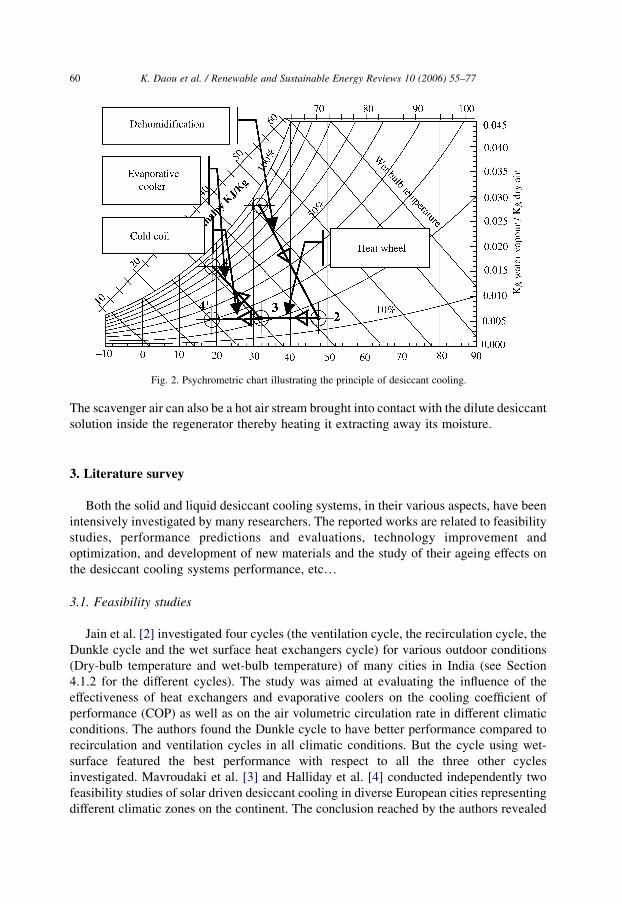
Fig. 2. Psychrometric chart illustrating the principle of desiccant cooling.
K. Daou et al. / Renewable and Sustainable Energy Reviews 10 (2006) 55–7760
The scavenger air can also be a hot air stream brought into contact with the dilute desiccant
solution inside the regenerator thereby heating it extracting away its moisture.
3. Literature survey
Both the solid and liquid desiccant cooling systems, in their various aspects, have been
intensively investigated by many researchers. The reported works are related to feasibility
studies, performance predictions and evaluations, technology improvement and
optimization, and development of new materials and the study of their ageing effects on
the desiccant cooling systems performance, etc.
3.1. Feasibility studies
Jain et al. [2] investigated four cycles (the ventilation cycle, the recirculation cycle, the
Dunkle cycle and the wet surface heat exchangers cycle) for various outdoor conditions
(Dry-bulb temperature and wet-bulb temperature) of many cities in India (see Section
4.1.2 for the different cycles). The study was aimed at evaluating the influence of the
effectiveness of heat exchangers and evaporative coolers on the cooling coefficient of
performance (COP) as well as on the air volumetric circulation rate in different climatic
conditions. The authors found the Dunkle cycle to have better performance compared to
recirculation and ventilation cycles in all climatic conditions. But the cycle using wet-
surface featured the best performance with respect to all the three other cycles
investigated. Mavroudaki et al. [3] and Halliday et al. [4] conducted independently two
feasibility studies of solar driven desiccant cooling in diverse European cities representing
different climatic zones on the continent. The conclusion reached by the authors revealed

K. Daou et al. / Renewable and Sustainable Energy Reviews 10 (2006) 55–77 61
that primary energy savings were achieved in all climatic conditions. A decline in energy
savings were noticed in highly humid zones. This decline was attributed to the high
temperature required to regenerate the desiccant in the climates of high humidity.
3.2. Performance studies
Alizadeh et al. [5] designed, optimized and constructed a prototype of a forced flow
solar collector/Regenerator. They employed an aqueous solution of calcium chloride as
desiccant and studied the influence of parameters, such as air and desiccant solution flow-
rates as well as the climatic conditions on the regenerator’s performance. The performance
of a regenerator was measured by the rate at which it removed water vapour from the weak
desiccant solution. The conclusion reached in that study was that the performance of the
regenerator increased as the air flow-rate increased. The solar collector efficiency
generally increased with the increase of the air mass flow-rate. The existence of an
optimum value of the air flow-rate at which the efficiency is maximal was also predicted. A
strong influence of the solar insolation on the collector/regenerator thermal performance
was noticed. Yadav [6] simulated a hybrid desiccant cooling system comprising the
traditional vapour compression air conditioning system coupled with a liquid desiccant
dehumidifier which was regenerated by solar energy. The study suggested that, when the
latent load constitutes 90% of the total cooling load, the system can generate up to 80% of
energy savings. Dai et al. [7] conducted a comparative study of a standalone VCS, the
desiccant-associated VCS, and the desiccant and evaporative cooling associated VCS. The
authors found an increase of cold production by 38.8–76% and that of COP by 20–30%.
Mazzei et al. [8] compared the operating costs of the desiccant and traditional systems
using the computer simulation tool and predicted operating cost savings of about 35% and
a reduction of thermal power up to 52%. In the case were the desiccant would be
regenerated by waste heat, the authors projected operating costs savings reaching up to
87%. They also found that cost savings and cooling power reduction increased when the
indirect evaporative cooling is used in conjunction with desiccant dehumidification. At
this point, it must be pointed out that savings on operating costs are dependent on the local
electricity fares, which vary from one country to another, even within the same country.
Henning et al. [9] conducted a parametric study of a combined desiccant/chiller solar
assisted cooling systems and showed not only their feasibility but also the primary energy
savings of up to 50% with a low increased overall costs. Shen et al. [10] used the molecular
sieve 13! desiccant wheel as adsorbent in a desiccant cooling system and simulated water
vapour and carbon dioxide removal from the process air. The authors conducted an
optimisation study involving the coefficient of performance, the temperature of
desorption, the overall number of transfer units, and the adsorption time. Techajunta
et al. [11] used silica gel as adsorbent and studied its regeneration with simulated solar
energy in which incandescent electric bulbs were used to simulate solar irradiation. The
regeneration rate was found to be strongly dependent on the solar radiation intensity while
its dependence on the air-flow rate was found to be weak. Sanjev et al. [12] studied
theoretically and experimentally a liquid desiccant cooling system made of a falling film
tubular absorber and a falling film regenerator. For the purpose of performance evaluation,
the authors defined wetness factors to characterise the uniformity of wetting of the surface
K. Daou et al. / Renewable and Sustainable Energy Reviews 10 (2006) 55–7762
of the contactors (dehumidifier and regenerator) by the desiccant solution. Their study is of
great interest for designing viewpoint, as it can help calculate more accurately the size of
the contactors. Kadoma et al. [13] investigated the impact of the desiccant wheel speed, air
velocity and regeneration temperature on the COP. The authors showed the existence of an
optimal speed and established that the COP decreased when the airflow rate increased and,
on the contrary, the temperature of regeneration and the cooling capacity had the same
evolution tendency. Shyi-Min et al. [14] reported a standalone solar desiccant enhanced
radiant cooling (SDRC), system inherited from the concept of desiccant enhanced
nocturnal radiation cooling and dehumidification (DESRAD) [11]. The system is a passive
desiccant-cooling scheme operating alternately according to the sequence of diurnal and
nocturnal natural cycle. Fathalah et al. [15] studied a heat recovery system. The system
studied was a solar energy driven LiBr–H2O absorption cooling machine. The heat was
recovered from the condenser of the machine and added to the driving solar energy. The
coefficient of performance was raised 1.2 times, hence 58% higher than that for the
absorption machine alone. The evaporator temperature was raised from 11.5 to 19.3 8C.
Arshad [16] undertook the study of a mathematical model of a liquid absorber
(dehumidifier). The said study has proved the increase of the performance with the
number transfer units (NTU) of heat transfer between the process air and the desiccant
solution. It is worthy noting here that the NTU is determined, in part, by the size of the
absorber. Adam [17] conducted a simulation study on a desiccant cooling system using
with aqueous solution of CaCl2 as liquid desiccant. The impact of certain parameters on
the system’s performance was studied. Those parameters include the desiccant solution’s
inlet temperature, the space sensible heat ratio (SHR), heat exchanger effectiveness, and
the ratio of liquid desiccant flow rate to the air flow rate (GL/Ga). The authors reached the
flowing conclusions:
†
The ratio GL/Ga has been found to have negligible effect on the system performance.†
Increasing the supply inlet temperature of liquid desiccant (up to certain limit) has theeffect of improving the system performance for lower values of SHR.
†
The system coefficient of performance at given space conditions and inlet temperatureof the liquid desiccant increased with the decrease in SHR.
†
The system performance decreased with the decrease of the heat exchangereffectiveness.
3.3. Desiccant material studies
The search for desiccant materials with improved sorption capacity has also benefited
the attention of researchers. Thus, in Boreskov Institute of Catalysis, in Russia the so-
called selective water sorbents for multiple applications were developed. Aristov [43–45]
has been the precursor of those hybrid materials developed by impregnating a host porous
material (silica gel, vermiculite) with hygroscopic salt (calcium chloride, lithium
chloride). The obtained product has a sorption capacity which can triple that of pure
host material. Shanghai Jiao Tong University has been contributing to this effort of search
for new sorption enhanced materials for several years. Liu et al. [46] developed a
composite material obtained by impregnating silica gel with calcium chloride
K. Daou et al. / Renewable and Sustainable Energy Reviews 10 (2006) 55–77 63
and obtained a composite adsorbent which was subsequently used to extract water from
atmospheric air. William [18] focused on the ageing process of the desiccant materials.
They found that desiccant materials subjected to cyclical hydrothermal adsorption/
desorption processes deteriorated more rapidly in the early time of its utilisation and the
deterioration stabilized afterwards at a negligibly small value during a period of time
whose length was dependent on the nature of the desiccant. This period was followed by a
more pronounced deterioration tendency which led to the final decay of the desiccant. The
degradation in desiccant performance was characterized by the drop in the equilibrium
water uptake rate. Alumina and silica gel were found to be ageing more severely after a
large number of adsorption/desorption cycles under desorbing temperature of 200 8C.
Therefore the authors recommended that their utilisation be limited to the applications
with low temperatures of regeneration. The 13! molecular sieve revealed more stability
and less severe loss of water adsorption capacity. The most stable among the desiccants
tested was, however, the LCIX which was capable of withstanding a large number of
adsorption/desorption cycles under a desorption temperature of 250 8C without significant
loss of its water vapour equilibrium capacity. Increase in the desiccant wheel speed was
also found to minimize the effect of desiccant aging on the system performance. This
means clearly that as the desiccant ages, the speed of desiccant wheel must be increased.
The study concluded that the slight decrease in adsorbent capacity of adsorption did not
affect significantly the overall performance of desiccant cooling systems.
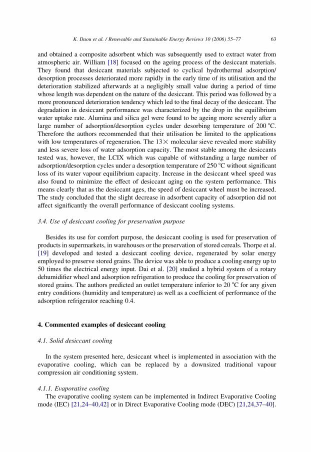
3.4. Use of desiccant cooling for preservation purpose
Besides its use for comfort purpose, the desiccant cooling is used for preservation of
products in supermarkets, in warehouses or the preservation of stored cereals. Thorpe et al.
[19] developed and tested a desiccant cooling device, regenerated by solar energy
employed to preserve stored grains. The device was able to produce a cooling energy up to
50 times the electrical energy input. Dai et al. [20] studied a hybrid system of a rotary
dehumidifier wheel and adsorption refrigeration to produce the cooling for preservation of
stored grains. The authors predicted an outlet temperature inferior to 20 8C for any given
entry conditions (humidity and temperature) as well as a coefficient of performance of the
adsorption refrigerator reaching 0.4.
4. Commented examples of desiccant cooling
4.1. Solid desiccant cooling
In the system presented here, desiccant wheel is implemented in association with the
evaporative cooling, which can be replaced by a downsized traditional vapour
compression air conditioning system.
4.1.1. Evaporative cooling
The evaporative cooling system can be implemented in Indirect Evaporative Cooling
mode (IEC) [21,24–40,42] or in Direct Evaporative Cooling mode (DEC) [21,24,37–40].

K. Daou et al. / Renewable and Sustainable Energy Reviews 10 (2006) 55–7764
In the DEC, water is sprayed directly into the process air stream. On the other hand, the
indirect evaporative cooling consists in using another air stream cooled directly and
evaporatively (called secondary air) as the heat sink to cool the process air (called primary
air) inside a heat exchanger, generally a plate heat exchanger (PHE). The DEC is an
adiabatic process in which the temperature of process air is lowered only at the expense of
higher moisture content in the air (see psychrometric chart at Figs. 3 and 4). This cycle of
evaporative cooling can operate efficiently in dry climates. In relatively more humid
climates, however, the IEC would rather be the best choice since it enables a real cooling
(reduction of enthalpy) without adding moisture into the process air (Figs. 3 and 4). It also
allows the use of reduced air volume in comparison with that would be required in direct
desiccant cooling.
Fig. 3 shows schematically an example of indirect evaporative cooling. It is composed
of several chambers separated by a heat conductor plate. In one chamber, water is sprayed
in the secondary air stream which is thus cooled down by a direct evaporative cooling. The
primary air is circulated inside the chamber contiguous to the one inside which the cooled
secondary air is circulated. Thus, it transmits its heat to the secondary air through the
separating plate, realising thus the indirect evaporative cooling. The primary air is used to
cool the space and the secondary air is dumped into the environment.
The effectiveness of an evaporative cooler is given by the following relation:
Effectiveness ZTemperature drop
Maximum temperature dropZ
Tdb KTout
Tdb KTwb
(1)
Temperature drop Z Dry bulb temperature KOutlet tmperature
Maximum temperature drop Z Dry bulb temperature KWet bulb temperature
Fig. 3. Indirect evaporative cooling.
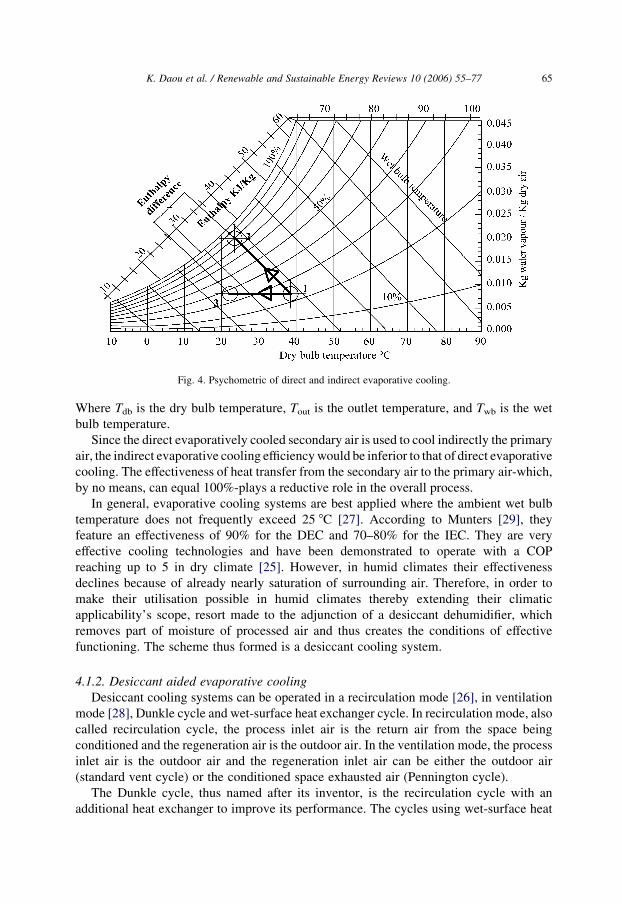
Fig. 4. Psychometric of direct and indirect evaporative cooling.
K. Daou et al. / Renewable and Sustainable Energy Reviews 10 (2006) 55–77 65
Where Tdb is the dry bulb temperature, Tout is the outlet temperature, and Twb is the wet
bulb temperature.
Since the direct evaporatively cooled secondary air is used to cool indirectly the primary
air, the indirect evaporative cooling efficiency would be inferior to that of direct evaporative
cooling. The effectiveness of heat transfer from the secondary air to the primary air-which,
by no means, can equal 100%-plays a reductive role in the overall process.
In general, evaporative cooling systems are best applied where the ambient wet bulb
temperature does not frequently exceed 25 8C [27]. According to Munters [29], they
feature an effectiveness of 90% for the DEC and 70–80% for the IEC. They are very
effective cooling technologies and have been demonstrated to operate with a COP
reaching up to 5 in dry climate [25]. However, in humid climates their effectiveness
declines because of already nearly saturation of surrounding air. Therefore, in order to
make their utilisation possible in humid climates thereby extending their climatic
applicability’s scope, resort made to the adjunction of a desiccant dehumidifier, which
removes part of moisture of processed air and thus creates the conditions of effective
functioning. The scheme thus formed is a desiccant cooling system.
4.1.2. Desiccant aided evaporative cooling
Desiccant cooling systems can be operated in a recirculation mode [26], in ventilation
mode [28], Dunkle cycle and wet-surface heat exchanger cycle. In recirculation mode, also
called recirculation cycle, the process inlet air is the return air from the space being
conditioned and the regeneration air is the outdoor air. In the ventilation mode, the process
inlet air is the outdoor air and the regeneration inlet air can be either the outdoor air
(standard vent cycle) or the conditioned space exhausted air (Pennington cycle).
The Dunkle cycle, thus named after its inventor, is the recirculation cycle with an
additional heat exchanger to improve its performance. The cycles using wet-surface heat
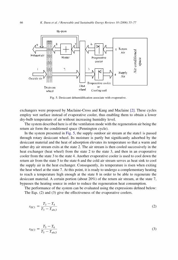
Fig. 5. Desiccant dehumidification associate with evaporative.
K. Daou et al. / Renewable and Sustainable Energy Reviews 10 (2006) 55–7766
exchangers were proposed by Maclaine-Cross and Kang and Maclaine [2]. These cycles
employ wet surface instead of evaporative cooler, thus enabling them to obtain a lower
dry-bulb temperature of air without increasing humidity level.
The system described here is of the ventilation mode with the regeneration air being the
return air form the conditioned space (Pennington cycle).
In the system presented in Fig. 5, the supply outdoor air stream at the state1 is passed
through rotary desiccant wheel. Its moisture is partly but significantly adsorbed by the
desiccant material and the heat of adsorption elevates its temperature so that a warm and
rather dry air stream exits at the state 2. The air stream is then cooled successively in the
heat exchanger (heat wheel) from the state 2 to the state 3, and then in an evaporative
cooler from the state 3 to the state 4. Another evaporative cooler is used to cool down the
return air from the state 5 to the state 6 and the cold air stream serves as heat sink to cool
the supply air in the heat exchanger. Consequently, its temperature is risen when exiting
the heat wheel at the state 7. At this point, it is ready to undergo a complementary heating
to reach a temperature high enough at the state 8 in order to be able to regenerate the
desiccant material. A certain portion (about 20%) of the return air stream, at the state 7,
bypasses the heating source in order to reduce the regeneration heat consumption.
The performance of the system can be evaluated using the expressions defined below:
The Eqs. (2) and (3) give the effectiveness of the evaporative coolers.
3EC1 ZT3 KT4
T3 KTwb;3
(2)
3EC2 ZT5 KT6
T5 KTwb;5
(3)

K. Daou et al. / Renewable and Sustainable Energy Reviews 10 (2006) 55–77 67
The coefficient of performance of the system is obtained by following relation:
COP ZQcool
Qregen
Z_maðh5 Kh4Þ
_maðh8 Kh7ÞZ
Rate of heat extracted
Rate of heat regeneration(4)
Neglecting the rate of added water vapour with respect to the air flow rate, the mass flow
rate of the air can be considered constant. Therefore, the effectiveness of rotary heat wheel
can be expressed by
3RHW ZT2 KT3
T2 KT6
(5)
The effectiveness of the desiccant wheel can be expressed by the relation (6).
3DW;1 ZT2 KT1
T8 KT1
(6)
The desiccant wheel’s effectiveness can also be expressed considering the real
performance of desiccant wheel with respect to the regeneration heat input. This second
expression of desiccant wheel’s effectiveness is given by
3DW;2 Zðw1 Kw2Þhv
h8 Kh7
(7)
where w and hv are the specific humidity and the latent heat of vaporisation of water,
respectively.
Another relation giving the performance of the desiccant wheel’s effectiveness has
been put forward by Van den Bulk et al. [27]. It is
3DW;3 Zw1 Kw2
w1 Kw2; ideal
(8)
Where w2,ideal is the ideal specific humidity of the air stream at the exit of the desiccant
wheel. Assuming that the air is completely dehumidified at this point, the value of w2, ideal
can be taken as zero.
The rates of moisture added to air by the evaporative coolers in the process and return
lines are given by the Eqs. (9) and (10) respectively.
_mw1 Z _maðw4 Kw3Þ (9)
_mw2 Z _maðw6 Kw5Þ (10)
Where _mw1; _mw2, are the mass rates at which the air is moistened by the evaporative
coolers placed in the supply line and return line, respectively; _ma designates the process air
mass flow rate.
The evolution of air treatment through the system is represented by the psychometric
chart in Fig. 6.
The desiccant-aided evaporative cooling has the following advantages:
†
It extends the climatic applicability scope of the evaporative cooling to the hot andhumid zones.

Fig. 6. Psychrometric representation of evaporative cooling aided desiccant cooling.
K. Daou et al. / Renewable and Sustainable Energy Reviews 10 (2006) 55–7768
†
The preheating being eliminated, energy and costs can be saved.†
The regeneration heat can be supplied by free energy sources.†
The system is environmental friendly since doesn’t use any Chlorofluorocarbon basedrefrigerant.
†
The sensible and latent cooling loads can be handled independently.†
The evaporative cooler can be replaced by the evaporator of a significant downsizedtraditional air conditioner, depending on the sensible heat ratio (SHR) of the room
being conditioned. This will be conducive to significant energy and cost savings.
†
The system entails low maintenance cost, since it functions at atmospheric conditions.4.1.3. Solid desiccant-aided radiant cooling
]The radiant cooling systems were first investigated in laboratory studies in
European countries in early 1990s [22]. They are of various types, including metal
ceiling panels, chilled beams, and tube embedded ceiling–walls–floors. They have
been investigated by many authors [22–23,47–51]. The very idea of space
conditioning by thermal radiation is motivated by the desire to decouple the energy
transfer mechanisms from the ventilation function while meeting the indoor air quality
requirements. This leads to drastic reduction of ventilation air volume. Stetiu [47]
showed, in a simulation study, that peak energy savings varying from 27 to 37% can
be realised by this decoupling strategy. The radiant cooling systems are expected to
feature interesting advantages compared with the vapour compression system. Firstly,
an ameliorated comfort is provided to the occupants because of the relative evenly
distribution of cooling, avoiding thereby the cold-draft effect. Secondly, the energy
needed for a pump to move water is lower than that needed to move air. Moreover,
displacement ventilation [22,23] method can be used to eliminate the need for any
ventilation fan.

K. Daou et al. / Renewable and Sustainable Energy Reviews 10 (2006) 55–77 69
The system constituted by a desiccant wheel and a heat wheel (as described in Section
4.1.2) can be employed advantageously in chilled-ceiling cooling system in hot climates to
dehumidifier the incoming air in order to prevent condensation on the ceiling walls and its
resulting discomfort. Fig. 7 shows a chilled-ceiling system in which chilled water is
circulated in series through the cold coil and the panel embedded in the roof. The incoming
air is dehumidified by a desiccant wheel and pre-cooled by heat wheel (the same
configuration as in Fig. 6) before been cooled further by the cold coil to the supply
temperature. The system has been proposed by Niu et al. [22] and modified by Zhang et al.
[23], by adding a heat recovery element (Total Heat exchanger) in order to improve its
efficiency. The sensible load is entirely handled by the chilled-ceiling radiant cooler while
the latent load is extracted by the desiccant. The use of the desiccant wheel here is of very
importance for comfort point of view if this system is to be used in a hot and humid
climatic zone. The incoming air is dehumidified by the desiccant thereby preventing
unwelcome condensation on the ceiling walls, which would result in discomfort inside the
space being conditioned.
The description of desiccant wheel system operation has already been made in
Section 4.1.2. The description holds also for this case. The psychrometric evolution
(Fig. 8) is different though, due the effect of the interiorly generated cooling by the
chilled ceiling.
In addition to the advantages cited above, inherent to chilled-ceiling itself, the
adjunction of desiccant can bring about the following advantages:
†
The sensible and latent loads are handled independently, the desiccant wheel removingthe former while the chilled-ceiling handling the latter, thereby realising the so-called
decoupled cooling [23].
Fig. 7. Desiccant associated Chilled-ceiling cooling.
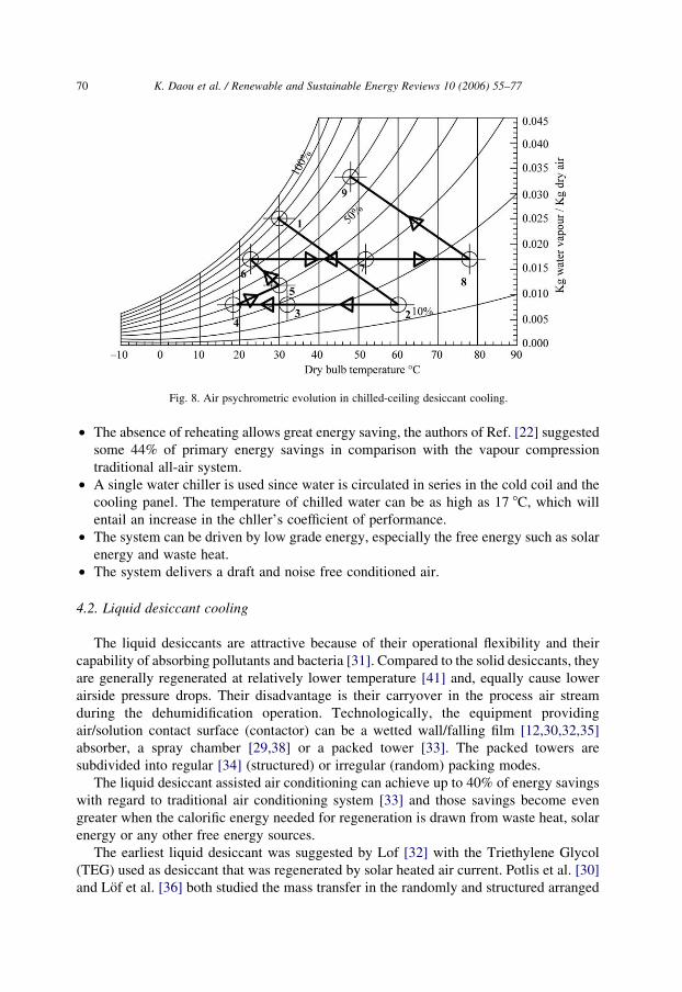
Fig. 8. Air psychrometric evolution in chilled-ceiling desiccant cooling.
K. Daou et al. / Renewable and Sustainable Energy Reviews 10 (2006) 55–7770
†
The absence of reheating allows great energy saving, the authors of Ref. [22] suggestedsome 44% of primary energy savings in comparison with the vapour compression
traditional all-air system.
†
A single water chiller is used since water is circulated in series in the cold coil and thecooling panel. The temperature of chilled water can be as high as 17 8C, which will
entail an increase in the chller’s coefficient of performance.
†
The system can be driven by low grade energy, especially the free energy such as solarenergy and waste heat.
†
The system delivers a draft and noise free conditioned air.4.2. Liquid desiccant cooling
The liquid desiccants are attractive because of their operational flexibility and their
capability of absorbing pollutants and bacteria [31]. Compared to the solid desiccants, they
are generally regenerated at relatively lower temperature [41] and, equally cause lower
airside pressure drops. Their disadvantage is their carryover in the process air stream
during the dehumidification operation. Technologically, the equipment providing
air/solution contact surface (contactor) can be a wetted wall/falling film [12,30,32,35]
absorber, a spray chamber [29,38] or a packed tower [33]. The packed towers are
subdivided into regular [34] (structured) or irregular (random) packing modes.
The liquid desiccant assisted air conditioning can achieve up to 40% of energy savings
with regard to traditional air conditioning system [33] and those savings become even
greater when the calorific energy needed for regeneration is drawn from waste heat, solar
energy or any other free energy sources.
The earliest liquid desiccant was suggested by Lof [32] with the Triethylene Glycol
(TEG) used as desiccant that was regenerated by solar heated air current. Potlis et al. [30]
and Lof et al. [36] both studied the mass transfer in the randomly and structured arranged

K. Daou et al. / Renewable and Sustainable Energy Reviews 10 (2006) 55–77 71
humidifier as well as in the regenerator and found that the mass transfer resistance in the
gas phase was negligible compared the liquid phase mass transfer resistance. Ali et al. [33]
also conducted similar study but on an inclined dehumidifier. The results yielded were
significant in the sense that they showed that the inclination angle played a significant role
in improving dehumidification and the cooling processes of liquid desiccant for both
inclined parallel and counter flow channels.
The performance of desiccant cooling system can be evaluated using the hereafter
mathematical expressions. These expressions were derived by the authors of Ref. [27].
The air moisture removal effectiveness is defined by
3m Zpa;i Kpa;o
pa;i Kps;i
(11)
Where Pa,i, Pa,o, Ps,i, designate respectively the air inlet water vapour pressure, air outlet
water vapour pressure, and the solution vapour pressure.
Likewise, the dimensionless temperature ration is defined by
3HE ZTs;o KTs;i
Ts;o KTc;i
(12)
Where Ts,o, Ts,i, Tc,i, designate, respectively, the desiccant solution outlet temperature, the
desiccant solution inlet temperature, the cooling medium inlet temperature.
The outlet temperature of the desiccant solution is derived from the expression (12) and
represented by the expression (13).
Ts;o ZTs;i K3HETc;i
1 K3HE
(13)
The relation linking the concentrations of inlet and outlet desiccant solution is given by
1
xo
Z1
xi
1 C_m
Gi
� �(14)
Finally the mass rate of moisture removal is obtained as
_m Z1
L
Cs3HE
ð1 K3HEÞðTs;i KTc;iÞKCabðTa;i KTs;iÞ
� �(15)
Where Cs and Ca designate the heat capacities of the solution and the air, respectively,
L designates the latent heat of condensation of water.
4.2.1. Vapour compression air conditioning aided liquid desiccant cooling system
An example of desiccant cooling application is represented in Fig. 9. Here, the cool
strong desiccant solution is sprayed onto the top of the dehumidifier through spraying
nozzles. By gravitation, it trickles through the structure of the dehumidifier where it gets
contact with the process air stream blown perpendicularly to its trickling flow direction.
Since, the cool and strong desiccant solution vapour pressure is less than that of the air
vapour pressure [17], water vapour migrates from the air stream to the desiccant solution
and condenses therein. Consequently, the heat of condensation and mixing are liberated
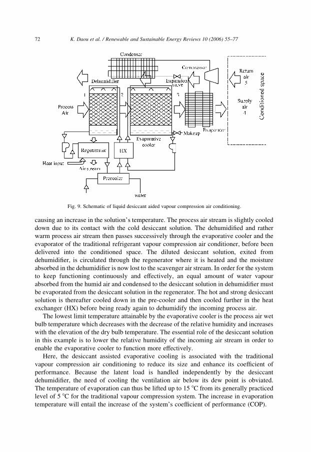
Fig. 9. Schematic of liquid desiccant aided vapour compression air conditioning.
K. Daou et al. / Renewable and Sustainable Energy Reviews 10 (2006) 55–7772
causing an increase in the solution’s temperature. The process air stream is slightly cooled
down due to its contact with the cold desiccant solution. The dehumidified and rather
warm process air stream then passes successively through the evaporative cooler and the
evaporator of the traditional refrigerant vapour compression air conditioner, before been
delivered into the conditioned space. The diluted desiccant solution, exited from
dehumidifier, is circulated through the regenerator where it is heated and the moisture
absorbed in the dehumidifier is now lost to the scavenger air stream. In order for the system
to keep functioning continuously and effectively, an equal amount of water vapour
absorbed from the humid air and condensed to the desiccant solution in dehumidifier must
be evaporated from the desiccant solution in the regenerator. The hot and strong desiccant
solution is thereafter cooled down in the pre-cooler and then cooled further in the heat
exchanger (HX) before being ready again to dehumidify the incoming process air.
The lowest limit temperature attainable by the evaporative cooler is the process air wet
bulb temperature which decreases with the decrease of the relative humidity and increases
with the elevation of the dry bulb temperature. The essential role of the desiccant solution
in this example is to lower the relative humidity of the incoming air stream in order to
enable the evaporative cooler to function more effectively.
Here, the desiccant assisted evaporative cooling is associated with the traditional
vapour compression air conditioning to reduce its size and enhance its coefficient of
performance. Because the latent load is handled independently by the desiccant
dehumidifier, the need of cooling the ventilation air below its dew point is obviated.
The temperature of evaporation can thus be lifted up to 15 8C from its generally practiced
level of 5 8C for the traditional vapour compression system. The increase in evaporation
temperature will entail the increase of the system’s coefficient of performance (COP).
K. Daou et al. / Renewable and Sustainable Energy Reviews 10 (2006) 55–77 73
This assemblage can be useful in humid climates where the wet bulb temperature is
fairly high. In such climates, a significantly downsized vapour compression air conditioner
can be supplemented with a desiccant assisted evaporative cooler in order to reach the
desired indoor temperature, thus enabling costs and energy savings and improving the
indoor air quality.
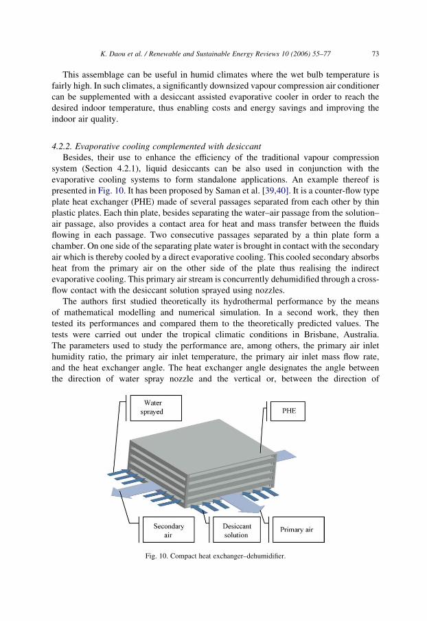
4.2.2. Evaporative cooling complemented with desiccant
Besides, their use to enhance the efficiency of the traditional vapour compression
system (Section 4.2.1), liquid desiccants can be also used in conjunction with the
evaporative cooling systems to form standalone applications. An example thereof is
presented in Fig. 10. It has been proposed by Saman et al. [39,40]. It is a counter-flow type
plate heat exchanger (PHE) made of several passages separated from each other by thin
plastic plates. Each thin plate, besides separating the water–air passage from the solution–
air passage, also provides a contact area for heat and mass transfer between the fluids
flowing in each passage. Two consecutive passages separated by a thin plate form a
chamber. On one side of the separating plate water is brought in contact with the secondary
air which is thereby cooled by a direct evaporative cooling. This cooled secondary absorbs
heat from the primary air on the other side of the plate thus realising the indirect
evaporative cooling. This primary air stream is concurrently dehumidified through a cross-
flow contact with the desiccant solution sprayed using nozzles.
The authors first studied theoretically its hydrothermal performance by the means
of mathematical modelling and numerical simulation. In a second work, they then
tested its performances and compared them to the theoretically predicted values. The
tests were carried out under the tropical climatic conditions in Brisbane, Australia.
The parameters used to study the performance are, among others, the primary air inlet
humidity ratio, the primary air inlet temperature, the primary air inlet mass flow rate,
and the heat exchanger angle. The heat exchanger angle designates the angle between
the direction of water spray nozzle and the vertical or, between the direction of
Fig. 10. Compact heat exchanger–dehumidifier.

K. Daou et al. / Renewable and Sustainable Energy Reviews 10 (2006) 55–7774
desiccant spraying direction and the horizontal. The return air from the conditioned
space was used as secondary air to improve the secondary side performance, since it
is usually drier than the outside air.
It was found notably that for the exchanger angle of 458, the effectiveness of
evaporative cooling could reach 75%, which is a good effectiveness value for an indirect
evaporative cooling application. It has also shown that, depending on the primary air flow
rate, the system could reach a good efficiency of humidity removal as well.
This system possesses a certain number of advantages. Firstly, it employs liquid
desiccant which is regenerated at a temperature relatively lower than the solid desiccant,
so solar energy and waste heat can readily be used to drive it. Secondly it is compact and
another stage of evaporative cooler can be added to it in order to reach even lower indoor
temperature. Thirdly the technology used is not sophisticated at all, therefore it can be
easily applied in the regions having abundant solar energy resource and therefore serious
cooling needs but lacking technological expertise.
5. Conclusion
Throughout this review, it has been seen that the desiccant cooling is a simple
technology which can be joined to other technologies to improve their efficiency.
Evaporative and radiant ceiling cooling for instance, are not effective in climates where
the wet-bulb temperature is high. Desiccant cooling can supplement them advantageously
by extending their climatic applicability’s scope. Its potential contribution in improving
indoor air quality, costs and energy savings, as well as environmental protection makes it
attractive at a time where depletion of energy resources and environmental degradation are
worldwide concerns. Although the desiccant cooling has its penalty which is the energy
required to reactivate (regenerate) the desiccant, it has been seen throughout this literature
review that, in overall, energy saving potential is significant. This potential is mainly due
to the elimination of the overcooling and the reheating. One of most important advantages
of desiccant cooling systems undoubtedly lies in the possibility of their regeneration by the
free energy such as waste and solar without any beforehand conversion. Amelioration of
indoor air quality brought about by its ability of removing pollutants and contaminants and
its environmental friendly nature make the desiccant cooling an appropriate and timely
technology.
The research of desiccant materials that can be regenerated under lower temperature,
(near-ambient) is the key of augmenting even greater the contribution that the desiccant
cooling can bring to the amelioration of comfort, energy and cost savings.
Acknowledgements
This work was supported by Chinese Scholarship Council (CSC) through the granted
scholarship No. 2001466006 and the National Fund for Distinguished Young Scholars of
China under the contract No. 50225621.
K. Daou et al. / Renewable and Sustainable Energy Reviews 10 (2006) 55–77 75
References
[1] Khattar MK. Design study of temperature and humidity control in enclosed spaces. Doctoral dissertation,
Florida Institute of Technology; April 1997.
[2] Jain S, Dhar PL. Evaluation of solid desiccant-based evaporative cooling cycles for typical hot and humid
climates. Int J Refrig 1995;18(5):287–96.
[3] Mavroudaki P, Beggs CB, Sleigh PA, Haliiday SP. The potential for Solar powered single-stage desiccant
cooling in southern Euro. Appl Thermal Engng 2002;22:1129–40.
[4] Halliday SP, Beggs CB, Sleigh PA. The use of solar desiccant cooling in the UK: a feasibility study. Appl
Thermal Engng 2002;22:1327–38.
[5] Alizadeh S, Saman WY. An experimental study of a forced flow solar collector/regenerator using liquid
desiccant. Solar Energy 2002;73(5):345–62.
[6] Yadav YK. Vapour-compression and liquid-desiccant hybrid solar space-conditioning system for energy
conservation. Renew Energy 1995;7:719–23.
[7] Dai YJ, Wang RZ, Zhang HF, Yu JD. Use of desiccant cooling to improve the performance of vapour
compression air conditioning. Appl Thermal Engng 2001;21:1185–205.
[8] Mazzei P, Minichiello F, Palma D. Desiccant HVAC systems for commercial buildings. Appl Thermal
Engng 2002;22:545–60.
[9] Henning H-M, Erpenbeck T, Hindenburg C, Santamaria IS. The potential of solar energy use in desiccant
cycles. Int J Refrig 2001;24:220–9.
[10] Shen CM, Worek WM. The second-law analysis of a recirculation cycle desiccant cooling system:
cosorption of water vapour and carbon dioxide. Atmos Environ 1996;30(9):1429–35.
[11] Techajunta S, Chirarattananon S, Exell RHB. Experiments in a solar simulator on solid desiccant
regeneration and air dehumidification for air conditioning in tropical humid climate. Renew Energy 1999;
17:549–68.
[12] Jain S, Dhar PL, Kaushik SC. Experiments studies on the dehumidifier and regenerator on a liquid desiccant
cooling system. Appl Engng 2000;20:253–67.
[13] Ginestet S, Stabat P, Marchio D. Control of open cycle desiccant cooling systems minimising energy
consumption. Centre d’energetique, Ecole de Mines de Paris [email protected], marchio@cenerg.
ensmp, [email protected].
[14] Shyi-Min LU, Wen-Jyh YAN. Development and experimental validation of a full-scale solar desiccant
enhanced radiative cooling. Renew Energy 1995;6(7):821–7.
[15] Fathalah K, Aly SE. Study of a waste heat driven modified packed desiccant bed dehumidifier. Energy
Convers Manage 1996;37(4):457–71.
[16] Khan AY, Martinez JL. Modelling and parametric analysis of heat and mass transfer performance of a
hybrid liquid desiccant absorber. Energy Convers Manage 1998;37(10):1095–112.
[17] Kinsara AA, Omar M, Rabghi A, Alsayes MM. Parametric study of an energy efficient air conditioning
system using liquid desiccant. Appl Thermal Engng 1997;18(5):327–35.
[18] Belding WA, Demast MPF, Holeman WD. Desiccant ageing and its effects on desiccant cooling system
performance. Appl Thermal Engng 1996;16(5):447–59.
[19] Thorpe GR. The modelling and potential applications of a simple solar regenerated grain cooling device.
Postharvest Biol Technol 1998;13:151–68.
[20] Dai YJ, Wang RZ, Xu YX. Study of a solar powered solid adsorption desiccant cooling system used for
grain stoage. Renew Energy 2002;25:417–30.
[21] Kessling W, Laevemann E, Peltzer M. Energy storage in open cycle liquid desiccant systems. Int J Refrig
1998;21(2):150–6.
[22] Niu JL, Zhang LZ, Zuo HG. Energy savings potential of chilled-ceiling combined with desiccant cooling in
hot and humid climates. Energy Building 2002;2001:487–95.
[23] Zhang LZ, Niu JL. A pre-cooling Munters environmental control desiccant cooling cycle in combination
with chilled-ceiling panels. Energy 2003;28:275–92.
[24] Joudi KA, Mehdi SM. Application of indirect evaporative cooling to variable domestic cooling load. Energy
Convers Manage 2000;41:1931–51.
K. Daou et al. / Renewable and Sustainable Energy Reviews 10 (2006) 55–7776
[25] Archibald J. New desiccant evaporative cooling cycle for solar air conditioning and water heating.
American Solar Roofing Company, 8703 Chipperndale Court Annandale, Va. 22003, e-mail: jarchibald@
americansolar.com.
[26] Shen CM, Worex WM. Second law analysis or a recirculation cycle desiccant cooling system: cosorption of
water vapour and carbon dioxide. Atmos Environ 1996;30(9):1429–35.
[27] Gandhidasan P. A simplified model for air dehumidification with liquid desiccant. Solar Energy 2004;76:
409–16.
[28] Kanoglu M, Ozdinc Carpinhoglu M, Yildirml M. Energy and Exegy analyses of an experimental ope-cycle
desiccant cooling system. Appl Thermal Engng 2004;24:919–32.
[29] Camargo JR, Ebinuma CD, Silveira J. Thermoeconomic analysis of an evaporative desiccant air
conditioning system. Appl Thermal Engng 2003;23:1537–49.
[30] Potlis, Vijay S. Development of dimensionless mass transfer correlations for packed bed liquid desiccant
contactors.: Colorado State University; 1994.
[31] Oberg V, Goswami DY. A Review of liquid desiccant cooling. In: Boer KW, editor. Advances in solar
energy, vol. 12. Boulder, CO: American Solar Energy Society, 1998; p. 431–470.
[32] Lof GOG. Cooling with solar energy. Proceedings of congress of solar energy, Tucson, Arison 1955
p. 171–89.
[33] Vafai AK. An investigation of heat and mass transfer between air and desiccant film in parallel and counter
flow channels. Appl Thermal Engng 2004;47:1745–60.
[34] Al-Farayedhi AA, Gandhidasan P. Evaluation of heat and mass transfer coefficient in gauge-type structured
packing air dehumidifier operating with liquid desiccant. Int J Refrig 2002;25:330–9.
[35] Jain S, Dhar PL, Kaushik SC. Experimental studies on the dehumidifier and regenerator of a liquid desiccant
cooling system. Appl Thermal Engng 2000;20:253–67.
[36] Lof GOG, Lenz TG, Rao S. Coefficients of heat and mass transfer in Packed bed suitable for solar
regeneration of aqueous lithium chloride solutions. J Solar Engng 1984;106:3387.
[37] Costelloe B, Finn D. Indirect evaporative cooling potential in air-water systems in temperate climates.
Energy Building 2003;35:573–91.
[38] Riffat SB, Zhu J. Mathematical model of indirect evaporative cooler using porous Performance of porous
ceramic evaporators for building cooling application. Energy Building 2003;35:941–9.
[39] Saman WY. Modelling and performance analysis of a cross-flow type plate heat exchanger for
dehumidification/cooling. Solar 2001;70(4):361–72.
[40] Saman WY, Alisadeh S. An experimental study of a cross-flow type plate heat exchanger for
dehumidification/cooling. Solar Energy 2002;1:59–71.
[41] Grossman G. Solar-powered systems for cooling, dehumidification and air-conditioning, vol. 1; 2002,
p. 53–62.
[42] Martinez FJR, Gomez EV, Marti RH, Martinez J, Gutierrez JM, Diez FV. Comparative study of two
different evaporative systems: An indirect evaporative cooler and a semi-indirect ceramic evaporative
cooler. Building Energy 2004.
[43] Aristov YuI, Tokarev MM, Gordeeva LG, Snytnikov VN, Parmon VN. New composite sorbents for sorlor-
driven technology of fresh water production from atmosphere. Solar Energy 1999;66(2):165–8.
[44] Aristov YuI, Restucia G, Tokarew MM, Buerger H-D, Freni A. Selective water sorbents for
multiple applications. 11. CaCl2 confined to expanded vermiculite. React Kinet Catal Lett 2000;71(2):
377–84.
[45] Tokarev M, Gordeeva L, Romannikov V, Glaznev I, Aristov Y. New composite sorbent CaCl2 in mesopores
for sorption cooling/heating. Int J Thermal Sci 2000;41:470–4.
[46] Liu YF, Wang RZ. Pore structure of new composite SiO2$xH2O$yCaCl2 with uptake of water air. Sci China,
Ser E 2003;46(5):551–9.
[47] Stetiu C. Energy and peak power saving potential of radiant cooling systems in US commercial buildings.
Energy Buildings 1999;30(3):127.
[48] Ardehali MM, Panah NG, Smith TF. Proof of concept modelling of energy transfer mechanisms for radiant
air conditioning panels. Energy Convers Manage 2002;45:2005–17.

K. Daou et al. / Renewable and Sustainable Energy Reviews 10 (2006) 55–77 77
[49] Laouadi A. Development of a radiant heating and cooling model for building energy simulation software.
Building Environ 2004;39:421–31.
[50] Miriel J, Serres L, Trombe A. Radiant ceiling panel heating-cooling systems: experimental and simulated
study of the performances, thermal comfort and energy consumptions. Appl Thermal Engng 2002;22:
1861–73.
[51] Lian Z, Zhang Y. Distribution ratio of radiant heat and its effect on cooling load. Int J Thermal Sci 2003;42:
311–6.