DESERT TECH REFLEX OPTIC Head Installation / Bolt Carrier Group Reassembly..... Magazine Spacer...
39
Transcript of DESERT TECH REFLEX OPTIC Head Installation / Bolt Carrier Group Reassembly..... Magazine Spacer...

2 3
Welcome to the proud family of Desert Tech firearm owners. In acquiring your new MDR (Micro Dynamic Rifle), you are the owner of the most versatile autoloading rifle in the world.
To get the most out of your MDR rifle, please read this manual from cover to cover before handling and operating the rifle for the first time.
TABLE OF CONTENTSFIREARM SAFETYSPECIFICATIONSFACTS ABOUT THE MDRRIFLE SETUP
RIFLE OPERATION.......................................................................................................................................................................................................................
7910 11
18
...................................................................................................................................................................................................................................................................................................................................................................................................................................................
............................................................................................................................................................................................................................................................................................................................................................................................................................................
CAREFULLY READ ALL OF THE OPERATING INSTRUCTIONS11141516
24
26
27
28
29
29
181920212223
Initial Setup/Conversion Kit Installation.............................................................................................................................................................................................Gas Adjustment.........................................................................................................................................................................................................................................Handguard Installation............................................................................................................................................................................................................................ Ejection System.........................................................................................................................................................................................................................................
a)b)c)d)
Conversion Kit Removal...........................................................................................................................................................................................................................
Bolt Head Removal / Bolt Carrier Group Disassembly................................................................................................................................................................
Bolt Head Swap..........................................................................................................................................................................................................................................
Bolt Head Installation / Bolt Carrier Group Reassembly...............................................................................................................................................................
Magazine Spacer Installation..............................................................................................................................................................................................................
Magazine Catch Installation.................................................................................................................................................................................................................
a)
b)
c)
d)
e)
f)
Function Check............................................................................................................................................................................................................................................Loading..........................................................................................................................................................................................................................................................Chamber Check...........................................................................................................................................................................................................................................Firing.............................................................................................................................................................................................................................................................Reloading.....................................................................................................................................................................................................................................................Unloading/Clearing..................................................................................................................................................................................................................................
a)b)c)d)e)f)
24CALIBER CONVERSION / DISASSEMBLY / REASSEMBLY........................................................................................

4 5
34
37
41
49
57
...................................................................................................................................................................
..................................................................................................................................................
............................................................................................................................................................................................................................
.....................................................................................................................................................................................................
..........................................................................................................................................................................................................................
..........................................................................................................................................................................................................
..................................................................................................................................................................................................................................................................
......................................................................................................................................................................................
DESERT TECH REFLEX OPTIC (DTRO)
ADVANCED DISASSEMBLY / REASSEMBLY
CLEANING AND MAINTENANCE
TROUBLESHOOTING
PARTS EXPLODED VIEW
WARRANTY POLICY
LIMITATION OF LIABILITY
NOTES
71
72
73
DTRO and DTRO Mount Installation.................................................................................................................................................................................................................Using and Zeroing the DTRO...............................................................................................................................................................................................................................
Bolt Head Disassembly.......................................................................................................................................................................................................................................Bolt Head Reassembly......................................................................................................................................................................................................................................Gas Block Disassembly......................................................................................................................................................................................................................................Gas Block Reassembly.......................................................................................................................................................................................................................................
a)b)
a)b)c)d)
a)b)c)d)e)f)g)
a)b)c)d)
GENERAL AND FIELD CLEANING...................................................................................................................................................................................................Receivers...................................................................................................................................................................................................................................................................Bolt Carrier Group (Assembled)..........................................................................................................................................................................................................................Bolt Carrier Group (Disassembled)....................................................................................................................................................................................................................Barrel Assembly......................................................................................................................................................................................................................................................Gas Valve..................................................................................................................................................................................................................................................................Ejector Panel and Chute Panel..........................................................................................................................................................................................................................Storage.......................................................................................................................................................................................................................................................................
Failure to Fire...........................................................................................................................................................................................................................................................Failure to Feed.........................................................................................................................................................................................................................................................Failure to Chamber.................................................................................................................................................................................................................................................Failure to Extract or Eject.....................................................................................................................................................................................................................................
MDR Main Rifle Assembly................................................................................................................................................................................................................................Upper Receiver.....................................................................................................................................................................................................................................................Lower Receiver.....................................................................................................................................................................................................................................................Barrel Assembly..................................................................................................................................................................................................................................................Bolt Carrier Group...............................................................................................................................................................................................................................................Bolt Head...............................................................................................................................................................................................................................................................Ejection Panel......................................................................................................................................................................................................................................................Chute Panel...........................................................................................................................................................................................................................................................Handguard and Pistol Grip..............................................................................................................................................................................................................................Conversion Kit.....................................................................................................................................................................................................................................................Trigger Group........................................................................................................................................................................................................................................................Sear Assembly Group Semi-Automatic.......................................................................................................................................................................................................Sear Assembly Group Automatic..................................................................................................................................................................................................................Desert Tech Reflex Optic (DTRO) and DTRO Mount................................................................................................................................................................................
3435
37383940
4142434445464748
49505153
5758596061626364656667686970
Magazine Spacer Removal..............................................................................................................................................................................................................................Conversion Kit Installation...............................................................................................................................................................................................................................
3031
g)h)
6 7
ALWAYS keep the firearm pointed in a safe direction.ALWAYS keep your finger off the trigger until ready to shoot.ALWAYS be sure of your target and what is beyond it.ALWAYS keep the firearm unloaded until ready to use. ALWAYS wear eye and ear protection. Know how to use the firearm safely. Consult the owners manual before use of the firearm. Use only the correct ammunition for your firearm. Never use alcohol, over-the-counter prescription drugs, or other drugs before or while shooting.Store firearms so they are not accessible to unauthorized persons and children.
WARNING!
KEEP OUT OF REACH OF CHILDREN!
IT IS DANGEROUS TO ALTER OR MODIFY THIS FIREARM IN ANY WAY. ANY ALTERATION OR MODIFICATION OF THE FIRING MECHANISM WILL RESULT IN THE FIREARM BECOMING UNSAFE. ANY ATTEMPT TO ALTER OR MODIFY THIS FIREARM WILL NULLIFY ALL WARRANTIES. THE USE OF REMANUFACTURED OR RELOADED AMMUNITION OF ANY KIND WILL ALSO VOID ALL WARRANTIES.
For more information on firearm safety, visit the NRA Education and Training website: gunsafetyrules.nra.org
WARNING!Follow all local, state, and federal laws regarding legal use of your Desert Tech MDR rifle.
This item may be regulated for export by the U.S. Department of State or the U.S. Department of Commerce. Please see our export policy at deserttech.com for details.
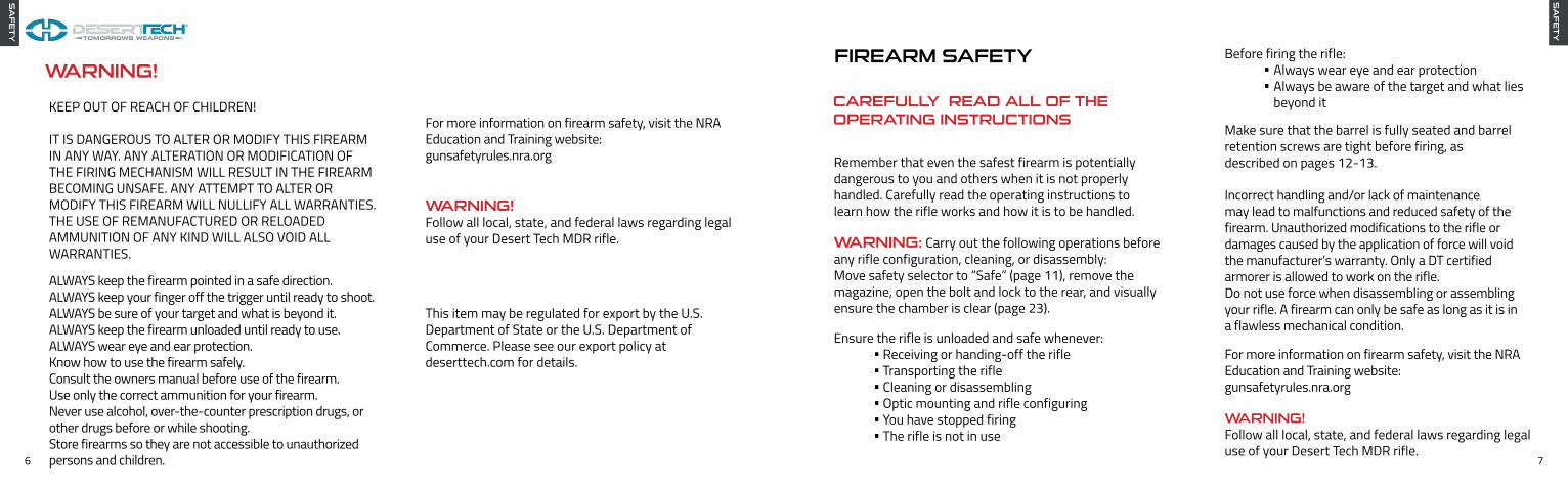
FIREARM SAFETY
Remember that even the safest firearm is potentially dangerous to you and others when it is not properly handled. Carefully read the operating instructions to learn how the rifle works and how it is to be handled.
WARNING: Carry out the following operations before any rifle configuration, cleaning, or disassembly: Move safety selector to “Safe” (page 11), remove the magazine, open the bolt and lock to the rear, and visually ensure the chamber is clear (page 23).
Ensure the rifle is unloaded and safe whenever: Receiving or handing-off the rifle Transporting the rifle Cleaning or disassembling Optic mounting and rifle configuring You have stopped firing The rifle is not in use
Before firing the rifle:Always wear eye and ear protectionAlways be aware of the target and what lies beyond itCAREFULLY READ ALL OF THE
OPERATING INSTRUCTIONSMake sure that the barrel is fully seated and barrel retention screws are tight before firing, as described on pages 12-13.
Incorrect handling and/or lack of maintenance may lead to malfunctions and reduced safety of the firearm. Unauthorized modifications to the rifle or damages caused by the application of force will void the manufacturer’s warranty. Only a DT certified armorer is allowed to work on the rifle. Do not use force when disassembling or assembling your rifle. A firearm can only be safe as long as it is in a flawless mechanical condition.
For more information on firearm safety, visit the NRA Education and Training website: gunsafetyrules.nra.org
WARNING!Follow all local, state, and federal laws regarding legal use of your Desert Tech MDR rifle.
SA
FE
TY
SA
FE
TY

8 9
REMEMBER: TREAT ALL FIREARMS AS ALWAYS LOADED.
LOOKING INTO THE END OF THE BARREL (MUZZLE) IS NOT RECOMMENDED AT ANY TIME.
SPECIFICATIONS
Rifle empty, no magazine: .223 Wylde.300 BLK.308 Win
.223 Wylde
.300 BLK
.308 Win
.223 Wylde
.300 BLK
.308 Win
TBDTBD8.35 lb (3.79 kg)
1 in 71 in 61 in 10
600 yards500 yards900 yards
26.2” (66.55 cm)26.2” (66.55 cm)26.2” (66.55 cm)
27.75” (70.48 cm)27.75” (70.48 cm)27.75” (70.48 cm)
Length (Rifle length with conversion)Minimum Length
Length with 16” Barrel
.223 Wylde
.300 BLK
.308 Win
.223 Wylde
.300 BLK
.308 Win
Weight (Rifle weight with conversion)
Rate of Twist
Firing CharacteristicsMaximum Effective Range:
Safety Selector Switch:
Magazine Releases:
Bolt Catches:
Handguards:
Ambidextrous, Safe, Fire, and (optional for LE and Military only) Full Auto
Ambidextrous, above trigger and forward of magazine well
Charging handle lock-back, last round hold-back, bolt release catch behind the magazine well
Standard and Reflex (for over-barrel suppression)
Torque SpecsHandguard Screws:Barrel Retention Screws:DTRO Mount:
30 in/lb80 in/lb30 in/lb
3.38 nm9.04 nm3.38 nm
Mechanical FeaturesMethod of Operation:Method of Feeding:Ejection:
Short Stroke Gas PistonDetachable Box MagazineRight or left forward ejection, side ejection optional
Sights Picatinny Rail (no taper)
BarrelType:Length:
Melonite Coated Light Profile16” (40.64 cm)with 16” Barrel:
and flash hider:
SP
EC
S
SA
FE
TY

10 11
The MDR has unrivaled portability because it is lightweight, compact, ergo-nomic, and balanced, with an overall length of 26.2” with a 16” barrel and a weight of 8.35 pounds.
The MDR is adaptable in both size and caliber. It can quickly convert between multiple calibers, and its gas-block incorporated picatinny rail and the Desert Tech barrel retention system allows for consistent return-to-zero between conversions. The barrel is also truly free-floated by design so barrel whip does not affect accuracy.
Adaptable
FACTS ABOUT THE MDRThe MDR is designed for future defense needs. Its compact size and superior ergonomics maximize its portability without sacrificing speed, power, or precision. The MDR allows mission-specific adaptability by changing the rifle’s length, sound signature, and caliber. Its fully-ambidextrous design allows seamless shoulder transitions. The MDR delivers advanced firepower for the future patriot.
KEY FEATURESPortable
AmbidextrousThe MDR is fully ambidextrous with no modification necessary. Our patented forward ejection mechanism and intuitive controls set a new bullpup standard for speed and precision.
ERGONOMIC FEATURE LIST• Ambidextrous charging handle• Ambidextrous magazine release above the trigger and central release forward of the magazine well, which facilitates rapid reloads• Ambidextrous Fire Selector• Last-round bolt catch/release for rapid reloads• Ambidextrous forward ejection, allows shooters to fire right- or
left-handed as well as swap the ejection sides in the field• Forward-ejection dust cover prevents debris from entering the
action and causing malfunctions• Crisp 4.6 lb trigger• Rear flush cup sling attachment points• MLOK handguard slots for accessory and sling mounting option• Weapon balance point is just rear of the pistol grip, giving the rifle a stable, yet highly maneuverable, weight distribution
FIREARM CONSTRUCTION• The barrel is attached to the receiver by two barrel retention
screws and a barrel locking lug• The polymer handguard is attached securely to the upper receiver
with a captured pin and two handguard reinforcement screws• A full-length, MIL-STD-1913 rail runs along the top of the
receiver and handguard, facilitating optics, night vision, thermals and other accessories. Rail segments attach to the sides for user-specified placement utilizing the MLOK attachment system
• The MDR is available in Black and Flat Dark Earth; all rifles are hard-coat anodized Black or Flat Dark Earth
RIFLE SETUPWARNING: Carry out the following operations before dismantling: Move safety selector to “Safe” remove the magazine, open the bolt and visually ensure the chamber is clear (page 23).
WARNING: DO NOT REMOVE ANY OF THE TORX RECEIVER SCREWS ON EITHER THE RIGHT OR LEFT SIDES OF THE MDR! IT WILL VOID THE WARRANTY AND CAUSE THE RIFLE TO MALFUNCTION!
1.
2.
3.
a) Conversion Kit Installation / Initial Setup
Remove the MDR receiver, barrel assembly, handguard, magazine, and the multi-tool from the MDR case.
Place the MDR on “Safe” by rotating the safety selector switch clockwise into the “Safe” position. (Counter-clockwise for left side manipulation) (Fig. a-1)
On the MDR handguard, use the T25 side of the multi-tool, loosen by two turns DO NOT REMOVE the two T25 torqueset handguard retention screws on the right and left side of the MDR Handguard. (Fig. a-2)
If removed, reinstall the handguard support backing plates to the inside of the MDR Handguard receiver with the raised portion facing to the outside of the handguard, and thread the handguard screws in from the outside of the handguard in until flush, then back them off two full turns. See page 65 for parts breakdown.
Fig. a-1
Fig. a-2
SE
TU
P

12 13
4.
5.
6.
Gripping the charging handle (right or left side), press down and pull to the rear of the charging channel, then lock it to the rear by lifting the charging handle upwards into the locking cutout and releasing it. The charging handle should remain in the locking cutout. (Fig. a-3)
Ensure the barrel lock screw is in the “Unlocked” position, and the two barrel retention screws are loose. (Fig. a-4)
Ensure the bolt head matches the chambering of the barrel. (Fig. a-5)
Insert the barrel assembly into the MDR receiver, barrel extension end first with the gas block rail at the 12 o’clock position. When properly seated in the receiver, there should be around a 1/16” (1.5mm) gap between the front edge of the upper receiver and the back edge of the gas block. (Fig. a-6)
7.
8.
9.
10.
Release the bolt assembly by pressing the charging handle downward to disengage it from the locked-back position.
Rotate the rifle to the left side. Using the 5mm hex wrench side of the multi-tool, rotate the barrel lock screw to the “Locked” position. (Fig. a-7)
Tighten and torque the two 5mm barrel retention screws to 80 in/lb. (Fig. a-7)
Fig. a-3
Fig. a-6
Fig. a-7
Fig. a-4
Fig. a-5
SE
TU
P
SE
TU
P

14 15
1.
2.
3.
Install the handguard on the MDR by sliding it over the barrel assembly, Desert Tech logo end first, with the rail at the 12 o’clock position. (Fig. c-1)
Push the captured handguard retention pin through from the left side to the right side of the MDR receiver until it snaps into position, flush on each side. (Fig. c-1)
Tighten handguard retention screws with a torque wrench, using a T25 head, to 30 in/lb. (Fig. c-1)
c) Handguard Installation
To set the gas setting to Adverse, rotate the gas valve within the gas block until the “A” is centered over the detent and the gas valve clicks into place. (Fig. b-1)
To set the gas setting to Suppressed, rotate the gas valve within the gas block until the “S” is centered over the detent and the gas valve clicks into place. (Fig. b-1)
2.
3.
1. To set the gas setting to Normal, rotate the gas valve within the gas block until the “N” is centered over the detent and clicks into place. (Fig. b-1)
The MDR has three gas settings: “N” (Normal), for regular fire in generally good conditions and without a suppressor; “A” (Adverse), for fire in bad conditions (heavy dust, excess humidity, mud, etc.); and “S” (Suppressed), for fire with a suppressor on the rifle.
b) Gas Adjustment
Fig. c-1
Fig. b-1
CAUTION: The gas block and gas valve may be hot if adjusting during a shooting session. In which case, it’s recommended you use the tip of a cartridge to rotate the gas valve, if no other tools are readily available.
SE
TU
PS
ET
UP
SE
TU
P

16 17
5. Repeat this process on the left side with the ejection panel to complete the ejection side reconfiguration process.
The MDR may also be fired without the chute panel, in which case the empty cartridges will eject in the standard 90-degree fashion from the rifle. Be careful to note which side it ejects from in this configuration, as hot casings may potentially hit the shooter’s face while firing if the ejection port is on the same side as the shooter’s head.
1.
2.
3.
4.
The MDR is 100% ambidextrous in its factory configuration; all user controls can be operated on either side and spent casings eject forward, away from the shooter’s face. However, depending on shooter preference, the ejection side can quickly be changed from right to left.
Place the MDR left side up. Use any instrument that has a small, strong edge to it, (such as the open end of a spent cartridge) and press the ejection panel release tab forward (Fig. d-1) and up to remove the ejection panel. (Fig. d-2)
Ensure the rifle is clear and safe, and the bolt assembly is in the charged, forward-most position.
WARNING: The charging handle MUST be in the forward position before removing the ejection panel and chute panel (page 23).
Rotate the MDR to the right side and, using the same method, remove the chute panel.
Replace the chute panel where the ejection panel was by inserting the front of the ejection panel front lips to the inside of the receiver ejection window, then pressing the back of the chute panel until the release tab snaps in place. See Fig. d-3, d-4 for panel reference images.
d) Ejection System
Fig. d-1
Ejection Panel Fig. d-2 Ejection Panel Fig. d-4
Chute Panel Fig. d-3
SE
TU
P
SE
TU
P

18 19
Charge the MDR again and squeeze the trigger, this time holding the trigger to the rear. Re-charge the rifle and release the trigger. There should be an audible “click” sound as the trigger resets. Repeat this multiple times to confirm functionality.
Insert an EMPTY magazine and charge the rifle. Pull the charging handle to the rear and the bolt carrier group should catch on the last round holdback catch. Lock the charging handle forward, then press the bolt catch release. The bolt carrier group should release and go into battery.
Function Check, Loading, Reloading, Unloading, Firing
RIFLE OPERATION
Before operating a firearm, ensure it is in a safe environment to do so, observing all the rules of firearm safety.
a) Function Check
1.
2.
3.
4.
5.
Ensure the rifle is clear and safe by removing the magazine, placing the rifle safety selector on “Safe” and cycling the rifle multiple times to ensure a clear chamber, and visually inspecting the chamber to confirm, (see page 23).
Point the rifle in a safe direction, charge the rifle, and squeeze the trigger. The trigger should not disengage from the hammer when the safety selector is in the “Safe” position.
Change the safety selector to “Fire”, then squeeze the trigger and release. The trigger should disengage from the sear, the hammer should make an audible ‘snap’ sound as it hits the firing pin/bolt carrier group.
b) Loading
1.
2.
3.
To load the MDR, first ensure it is in a safe environment to do so, observing all the rules of firearm safety, and the safety selector switch is in the “Safe” position (page 11) Ensure the cartridges loaded into the magazine match the chambering of the conversion kit.
Insert cartridges into the magazine by pressing the cartridge (parallel to the magazine) downwards into the magazine. Ensure the face of the cartridge is at the rear-most position inside the magazine. (Fig. b-1)
Repeat until the magazine is full, or less, if desired.
OP
ER
AT
ION
OP
ER
AT
ION
Fig. b-1
Note: For reliable function with the .308/7.62 NATO chambering, it isrecommended that only non-steel cased ammunition be used in the MDR.

20 21
c) Chamber Check
1.
4.
5.
6.
To do a fast chamber check, open the dust cover by pulling the top of the dust cover plate outwards. The retention spring will do the rest to open it. (Fig. c-1)
There is a chamber check window in the chute panel of the MDR.
Ensuring the MDR is on “Safe” and pointed in a safe direction, insert the loaded magazine (bullets forward, Fig. b-1) into the magazine well until it is seated with an audible “click” sound. A quick tug down on the magazine is advisable to ensure it’s locked in position.
Grasp the charging handle, press down and pull all the way to the rear of the charging handle channel, then release. Do not slowly release, or “walk”, the bolt forward, as it may not fully seat the cartridge in the chamber.
The MDR is now loaded.
2.
3.
Press down and slowly pull back part way on the charging handle, observing the chamber check window as you do so. As the bolt face comes back, it will either be pulling a cartridge with it, indi-cating the chamber is loaded (Fig. c-2), or it will have nothing (Fig. c-3), indicating an empty chamber.
Once satisfied, release the charging handle back into battery. It is advisable when clearing the rifle to do multiple chamber checks to ensure the rifle is absolutely clear of any cartridges.
d) Firing
1.
2.
Shoulder the rifle by placing the recoil pad to the pocket of your shoulder, and resting your cheek on the MDR cheekrest.
Follow all firearm safety rules when firing a weapon. Eye protection and hearing protection is recommended when operating any firearm. Permanent hearing and vision damage is very likely if ignored.
Grip the pistol grip with your firing hand, and the handguard with your support hand. Use your support hand to keep the rifle pressed to your shoulder, and keep your firing hand firm but not tight on the pistol grip.
OP
ER
AT
ION
OP
ER
AT
ION
Fig. c-3
Fig. c-2
Fig. c-1
WARNING: This does not replace a full visual inspection inside of the chamber, which requires removal of the chute panel.

22 23
e) Reloading
1a.
1b.
1c.
3.
4.
Primary Magazine Release:Press the square magazine release button above trigger and the magazine will release. (Fig. e-1,)
Secondary Magazine Release:Press the magazine release catch in front of the magazine well and the magazine will release. (Fig. e-2, A)
Magazine Empty Reload:Upon firing the last round, the bolt will lock to the rear, enabling faster reloads than from a closed bolt. (Fig. e-2, B)
The MDR comes with two ambidextrous options for releasing the magazine.
When on target and ready to fire, rotate the safety selector switch to “Fire.” (Fig. d-1)
Squeeze the trigger until the rifle fires. Release the trigger so it resets, and repeat the process until the magazine is empty or until desired firing is complete.
Note: Upon firing the last round, the empty casing will be retained in the chute panel until the bolt is sent back into battery, at which time the empty casing will be ejected. This is normal and not a malfunction.
OP
ER
AT
ION
Fig. e-1
Fig. e-2
Fig. d-1
f) Unloading / Clearing
1.
2.
3.
4.
To unload/clear the MDR, first rotate the fire selector switch to “Safe” (Fig. f-1)
Remove the magazine by pressing the magazine release button above the trigger or by pressing the magazine release down (in front of the magazine well) and pull the magazine downward until it clears the rifle. (Fig. f-2)
Pull the charging handle quickly to the rear and release multiple times to clear any remaining cartridge(s). Pull the charging handle rearward quickly to reliably eject non-fired cartridges from the rifle. Ejecting them slowly can cause malfunctions as they enter the ejection chute. (Fig. f-3)
Pull the charging handle back slowly and view the chamber check window to ensure and confirm there’s no cartridge still in the chamber. (Fig. f-4)
Fig. f-1
Fig. f-3
Fig. f-4
Fig. f-2
OP
ER
AT
ION
B
A
WARNING: This does not replace a full visual inspection inside of the chamber, which requires removal of the chute panel. (See pages 16-17)

24 25
a) Conversion Kit Removal
CALIBER CONVERSION / DISASSEMBLY / REASSEMBLY
1.
2.
3.
4.
Ensure the rifle is safe by following the Unloading/Clearing procedures on page 23. Follow steps a-h (pages 24-33) for caliber conversion process.
Slide the handguard off the front of the MDR. (Fig. a-1)
Lock the charging handle to the rear of the charging channel.
Using the 5mm hex side of the multi-tool, loosen the two barrel retention screws one full turn each and rotate the barrel locking screw to the “Unlock” position. (Fig. a-2)
Fig. a-1
5.
6.
7.
8.
9.
Using the T25 side of the multi-tool, loosen the handguard retention screws. Press the captured handguard retention pin through from the right side to the left side of the MDR receiver until it snaps into position. (Fig. a-1)
Remove the barrel assembly. (Fig. a-3)
Slowly release the charging handle, allowing the bolt assembly to go to the forward-most position.
Place the MDR on its right side. Use any instrument that has a small, strong edge to it, (such as the open end of a spent cartridge) press the ejection release tab forward and up to remove the ejection panel. (Fig. a-4)
Press the captured rear and middle takedown pins out from the right to the left and tilt the rear of the upper receiver up. (Fig. a-5)
Pull down and rearward on the charging handle to bring the bolt carrier assembly rearward, then grasp the bolt carrier guide plate and pull the recoil spring support rearward and out of the rifle.
Fig. a-5
Fig. a-4
Fig. a-3
Fig. a-2
CO
NV
ER
SIO
N &
DIS
AS
SE
MB
LY
CO
NV
ER
SIO
N &
DIS
AS
SE
MB
LY

26 27
CO
NV
ER
SIO
N &
DIS
AS
SE
MB
LY
CO
NV
ER
SIO
N &
DIS
AS
SE
MB
LY
b) Bolt Head Removal / Bolt Carrier Group Disassembly
1.
2.
3.
4.
1.
2.
Use a pen or a 1/8 Punch, press the firing pin retaining pin (FPRP) out of the bolt carrier group from the right to the left. (Fig. b-1)
When swapping the bolt head during a caliber conversion, ensure the bolt head caliber label on the extractor matches the chambering of the conversion kit being installed. (Fig. c-1)
Follow the Bolt Head Installation / Bolt Carrier Group Reassem-bly steps on page 28 for bolt head installation instructions. For further bolt head disassembly, refer to Advanced Disassembly on page 37.Tilt the bolt carrier group upwards and drop the firing
pin out. (Fig. b-1)
Press and rotate the bolt head to the rear, then rotate the bolt guide pin 90-degrees to remove; pull it up and out. (Fig. b-2)
Pull the bolt head out from the bolt carrier. (Fig. b-2)
Fig. b-1
FPRP
Firing Pin
Fig. b-2
Fig. c-1
c) Bolt Head Swap

28 29
1.
2.
Push inward on the magazine release rod. (Fig. f-1)
Rotate the magazine catch down. (Fig. f-2)
f) Magazine Catch Installation / Conversion
Fig. f-1
Fig. e-1
1.
2.
3.
To install the magazine spacer for AR-15/M16 magazine compatibility, ensure the rifle is clear and the bolt is forward.
Press and hold the magazine release. (Fig. e-1)
Insert the magazine spacer into the magazine well in the lower receiver from the bottom until it snaps into position. (Fig. e-1)
e) Magazine Spacer Installation (.223 and .300 BLK)
4. Release the magazine release.
CO
NV
ER
SIO
N &
RE
AS
SE
MB
LY
CO
NV
ER
SIO
N &
RE
AS
SE
MB
LY
Fig. d-2
d) Bolt Head Installation / Bolt Carrier Group Reassembly
Insert the bolt head into the bolt carrier, with the large bolt guide pin hole in the 12 o’clock position. (Fig. d-1)
Rotate the bolt head to approximately the 1 o’clock position and insert the bolt guide pin, with the top plate of the pin parallel to the bolt carrier. (Fig. d-1)
Note: Ensure the caliber on the bolt head matches the barrel you have installed. (page 12, Fig. a-5)
Pull the bolt head forward and rotate the bolt guide pin 90 degrees, then insert the firing pin (small tip forward) into the bolt carrier until it sits just below, flush with the back of the bolt carrier. (Fig. d-2)
Insert the firing pin retention pin in the bolt carrier from the left, and press until flush. (Fig. d-2)
1.
2.
3.
4.
Fig. d-1
Bolt Guide Pin
Bolt Carrier
FPRP
Firing Pin
Bolt Head

30 31
Fig. h-1
Open the upper receiver by pressing the rear and center takedown pins to the outward most position and tilt the upper receiver up from the lower receiver, if it’s not already open.
Rotate the rifle to the left side. Using the 5mm hex wrench side of the multi-tool, rotate the barrel lock screw to the “Locked” position, and torque the barrel retention screws to 80 in / lb. (Fig. h-2)
h) Conversion Kit Installation
1.
2.
3.
Insert the barrel assembly into the MDR receiver, barrel exten-sion end first with the gas block rail at the 12 o’clock position. When properly seated in the receiver, there should be a 1/16” (1.5mm) gap between the front edge of the upper receiver and the back edge of the gas block rail tower. (Fig. h-1)
Fig. h-2
CO
NV
ER
SIO
N &
RE
AS
SE
MB
LY
CO
NV
ER
SIO
N &
RE
AS
SE
MB
LY
3.
4.
Using a small flat tool, tap the back of the magazine conversion bar until it slides off. (Fig. f-2)
Fig. f-2
Fig. f-3
Press the .223/.300 BLK magazine conversion bar onto the magazine release main bar and rotate the magazine catch back into place. (Fig. f-3)
1.
2.
3.
Push the rear and middle takedown pins to their furthestoutward position.
Lift the back of the upper receiver to expose the magazine conversion latch.
Push the magazine release while pushing the magazine conversion latch in and down. The magazine spacer should slide out the bottom of the magazine well. (Fig. g-1)
g) Magazine Spacer Removal (.223 and .300 BLK)
Fig. g-1

32 33
Press the captured handguard retention pin through from the left side to the right side of the MDR receiver until it snaps into position, flush on each side. (Fig. h-6)
Tighten handguard retention screws with a torque wrench, using a T25 head, to 30 in/lb. (Fig. h-6)
7.
8.
9.
10.
Fig. h-6
Install the handguard on the MDR by sliding it over the barrel assembly, Desert Tech logo end first, with the rail at the 12 o’clock position. (Fig. h-6)
Fig. h-5
On the MDR handguard, pop the captured handguard retention pin out to its open-most position. (Fig. h-5)
Ensuring the bolt head is fully forward, install the bolt carrier assembly into the back of the MDR upper receiver first ensur-ing the charging handle is forward. Next, align the slots of the operating rod guide with the MDR upper receiver operating guide rod channels as well as the bolt carrier slot alignment with the upper receiver channels just below them, then seat the bolt carrier group fully forward. (Fig. h-3)
Replace the ejection panel by inserting the front of the panels lips to the inside of the receiver ejection window, then pressing the back of each sides panels until the release tab snaps in place. (Fig. h-4)
Close the receiver and press the takedown pins into place.
4.
5.
6.
Fig. h-4
Fig. h-3
CO
NV
ER
SIO
N &
RE
AS
SE
MB
LY
CO
NV
ER
SIO
N &
RE
AS
SE
MB
LY

34 35
b) Using and Zeroing the DTRO
1.
2.
3.
4.
5.
To turn the DTRO on, press the button at the front of the optic. To turn it off, press and hold the button for approximately two seconds. (Fig. b-1)
The DTRO takes a CR2032 3v battery. It is located on the bottom of the optic. Once mounted, optic removal will be necessary to change the battery. (Fig. a-2, page 34)
The DTRO has two adjustment screws, and two lock screws. The top screw adjusts the up/down and the right side screw adjusts the left/right. (Fig. b-2)
Before adjusting the zero, use the included flathead screwdriver to loosen (DO NOT REMOVE) the two set screws on the back of the DTRO.
To move the dot left or right, use the included screwdriver to turn the screw on the right side of the DTRO counter-clockwise or clockwise, respectively. (Fig. b-3)
MR
O
L
Fig. b-1
Fig. b-2
Lock Screws
Up/Down
Left/Right
MR
O
a) DTRO and DTRO Mount Installation
DESERT TECH REFLEX OPTIC (DTRO)
1.
2.
3.
4.
5.
To mount the DTRO to the MDR using the DTRO mount, begin by loosening the rail attach point screw on the DTRO mount with the supplied 2.5mm hex key. Then place the DTRO mount on the MDR gas block rail section with the DTRO mount angled back toward the shooter and tighten the DTRO mount screw with a torque wrench to 30 in/lb. (Fig. a-1)
Install the DTRO to the DTRO mount by aligning the DTRO mounting pegs with the DTRO Seal Plate and the bottom of the DTRO, ensuring the lens is at the front of the DTRO mount. (Fig. a-2)
Install the CR2032 3v battery in the bottom of the DTRO with the positive side facing down. (Fig. a-2)
Fasten the DTRO to the DTRO mount using the two supplied 2.5mm hex screws with the supplied 2.5mm hex key. Tighten snug, taking caution to not strip out the hex screw head, or to over-tighten the screws on the sight body. (Fig. a-2)
Removal is the reverse of installation.
Fig. a-1
Fig. a-2

36 37
ADVANCED DISASSEMBLY
a) Bolt Head Disassembly
1.
2.
3.
Place the bolt body on a solid surface and press down on the extractor with your finger behind the rib, right above the extractor pin. Using a 3/32 punch and mallet or brass hammer, press the extractor pin out from the left to the right to remove the pin and release the extractor assembly from the bolt body. (Fig. a-1)
Separate the extractor spring assembly from the extractor by pulling it off the extractor. (Fig a-2)
Separate the extractor bump stop by popping it out of the extractor spring with your finger or a small pointed object if it’s stuck. (Fig. a-3)
Fig. a-1
Fig. a-2
Fig. a-3
AD
VA
NC
ED
6.
7.
To move the dot down or up, use the included screwdriver to turn the top screw counter-clockwise or clockwise, respectively. (Fig. b-4)
After each zero adjustment, re-tighten the lock screws to ensure no zero shift occurs during firing.
L
L
Fig. b-3
Fig. b-4
MR
O

38 39
AD
VA
NC
ED
AD
VA
NC
ED
b) Bolt Head Reassembly
1.
2.
3.
Press the extractor bump stop into the extractor spring. (Fig. b-2)
Press the extractor spring assembly onto the extractor spring catch point, until it snaps in position. (Fig. b-3)
Press the extractor assembly into the extractor slot on the bolt body, aligning the pin hole cutouts, then press the extractor pin through from right to left. It may be necessary to lightly tap the pin through the hole using a brass hammer. (Fig. b-4)
Fig. b-2 Fig. b-3
Fig. b-4
Fig. b-1
CAUTION: Before reassembling the bolt carrier group, ensure you have the correctly chambered extractor for the conversion kit you intend to install (Fig. b-1). Failure to comply can cause malfunctions, internal damage, or acomplete failure of the firing cycle.
c) Gas Block Disassembly
1.
2.
Rotate the gas valve 180 degrees to where the “A” firing condi-tion rib is at the 12 o’clock position, then pull the gas valve out of the gas block. It may be necessary to depress the detent to allow rotation. Use a punch tool if necessary. (Fig. c-1)
Using a 5/16” punch or similar object, push the piston out the front of the gas block from the back. (Fig. c-2)
Fig. c-1
Fig. c-2
WARNING: Do not remove the rings from the gas piston, it is unnecessary for maintenance or cleaning and will void the warranty if tampering is evident.
.308.223 & .300

40 41
AD
VA
NC
ED
Fig. d-2
Fig. d-1
d) Gas Block Reassembly
Install the piston into the gas block, pressing it to the rear-most position. (Fig. d-1)
Install the gas valve in the front of the gas block with the firing condition rib at the 12 o’clock position, then rotate it until the detent clicks into the desired firing condition setting. (Fig. d-2)Use a punch tool to depress the detent to allow initial rotation.
1.
2.
CLEANING AND MAINTENANCE
Comprehensive knowledge of how to service and handle firearms is of great importance. Experience has shown that most failures, which occur while operating a firearm, are due to negligence in maintenance. Special attention must be paid to cleaning, lubricating, and inspecting the rifle; this will de-termine whether or not the rifle will function properly. In order to maintain accuracy, the barrel must be maintained properly. The receivers, bolt carrier group, and other moving parts of the rifle must be kept clean and lightly lubricated to ensure proper operation of the rifle.
GENERAL
Ensure the rifle is clear and safe by removing the magazine, placing the rifle fire selector on “Safe” and cycling the rifle multiple times to ensure a clear chamber, visually inspecting the chamber to confirm.
Desert Tech recommends cleaning the barrel when accuracy begins to deteriorate, using bore cleaning foam and the properly sized bore snake. Follow cleaner product instructions when cleaning the barrel.
Desert Tech recommends cleaning the MDR every 1000 rounds in clean environments. Dependent upon environmental conditions, cleaning more often may become necessary.
Note: When the rifle is purchased, or after it has been stored for long periods of time, the rifle should be cleaned before use.
FIELD CLEANING
CL
EA
N

42 43
CL
EA
N
1.
2.
3.
4.
5.
Separate the upper receiver from the lower receiver by popping out the three (3) captured takedown pins. (Fig. a-1)
With a brush and CLP, scrub the magazine well, then wipe it clean with a rag.
If the hammer and sear mechanisms are dirty, scrub them lightly with a brush and wipe clean as best as possible. (Fig. a-2)
Apply a drop of CLP to the trigger sear.
Using canned air or a low-PSI air compressor, blow out the lower receiver if there are signs of excess dust or fouling buildup. Wipe clean with a rag and/or soft brush.
a) Receivers
Fig. a-1
Fig. a-2
Remove the bolt carrier group, ejector panel, and chute panel by following the steps on page 24-25.
1.
2.
3.
4.
5.
Apply CLP to the the bolt carrier group, both sides (bolt lugs, extractor, bolt guide pin, bolt head, operation rod guide), and allow it to soak for a minute or so.
With either a plastic or wire brush, scrub the bolt carrier and bolt head, removing any carbon or any fouling buildup.
Wipe down the bolt carrier group with a rag until all fouling is removed.
Apply CLP to the the collar, bolt lugs, the extractor cutout, bolt guide pin, bottom bolt carrier guides, and spring guide. (Fig. b-1)
b) Bolt Carrier Group (Assembled)
Fig. b-1
CL
EA
N

44 45
Disassemble the bolt carrier group by following the steps on page 26.
1.
2.
3.
4.
With either a plastic or wire brush, scrub the bolt carrier, bolt body, bolt guide pin, firing pin, and firing pin retainer, removing any carbon or any fouling buildup.
Wipe down the bolt carrier group with a rag until all fouling is removed.
c) Bolt Carrier Group (Disassembled)
Apply CLP to the the bolt carrier group (bolt head and bolt lugs, extractor, bolt guide pin, bolt carrier, firing pin, firing pin lock), and allow it to soak for a minute or so. (Fig. c-1)
Fig. c-1
Using a caliber-appropriate sized bore snake with CLP, clean the bore of the rifle. It may take multiple passes to remove bore fouling.
Run cleaning patches with CLP applied through the rifle barrel until the patches come through clean. (Fig. d-1)
Re-apply CLP to the bolt carrier, bolt body, bolt guide pin, firing pin, and firing pin lock, extractor cutout, bottom bolt carrier guides, and spring guide. (Fig. c-1)
Reassemble the bolt carrier group following the steps on page 28.
CL
EA
N
1.
2.
3.
4.
5.
5.
6.
d) Barrel Assembly
Scrub the chamber lugs and feed ramps with a wire brush and CLP.
Wipe the fouling out of the chamber lugs and off the feed ramps with a rag.
Clean out the gas block with a wire brush, wipe clean with a rag, apply light CLP. (Fig. d-1)
Fig. d-1
CL
EA
N

46 47
Remove the gas valve from the gas block by following the removal steps on page 39.
Scrub off and wipe away any carbon from the gas valve and gas piston.
Apply a light coating of CLP to the gas adjustment valve and the large ring on the gas piston. (Fig. e-1)
1.
2.
3.
e) Gas Valve
Fig. e-1
WARNING: Do not remove the rings from the gas piston, it is unnecessary for maintenance or cleaning, and will void the warranty if tampering is evident.
CL
EA
N
Remove the chute panel and ejection panel by following the steps on pages 16-17.
Apply CLP to the insides of the chute panel and ejection panel, then, with a wire brush, scrub the insides of the chute and ejection panels.
Wipe down the chute and ejection panels with a rag until all fouling is removed.
Apply CLP to both panels release tabs, and to the ejection panel actuating joints. (Fig. f-1)
Reinstall the bolt carrier group, chute panel, and ejection panel.
1.
2.
3.
4.
5.
f) Ejector Panel and Chute Panel (Assembled)
Fig. f-1
CL
EA
N

48 49
1.
2.
3.
Ensure the rifle chamber is clear and the magazine is unloaded and the rifle is on ”S” (Safe) position.
If possible, store rifle in a gun safe, with the butt of the stock resting on the ground and the muzzle pointed up.
If a safe is unavailable, store in a secure location, ensuring it is out of reach of children.
g) Storage
WARNING!KEEP OUT OF REACH OF CHILDREN!
ST
OR
E
TROUBLESHOOTINGa) Failure to FireWARNING: If the rifle fails to fire with a live round in the chamber of a hot barrel (a misfire or jam), keep the rifle pointed in a safe direction, place the safety slide on the ”S” (Safe) position, and wait 30+ seconds before trying to remove the round. If you cannot remove the round, remove the magazine and wait at least 15 minutes with the rifle pointed in safe direction, then proceed from the following troubleshooting procedures to safely determine the cause of the malfunction and return the rifle to a safe condition.
1. Empty magazine.
2. Empty chamber (loaded magazine).
3. Defective cartridge.
Reload MDR with a loaded magazine.
Ensure magazine is fully inserted, charge the rifle. To ensure a round went into battery after charging, pull the Charging Handle back approx-imately 2” and observe the Chamber Check Window.
Possible Causes:-Magazine improperly seated-Charging handle not pulled back far enough when charging MDR.
Inspect primer. If fully indented, wait for 15 minutes then discard safely. If not fully indented, check firing mecha-nism.
Malfunction Remedial Action
Malfunction Remedial Action
TR
OU
BL
ES
HO
OT

50 51
TR
OU
BL
ES
HO
OT
Pull charging handle all the way to the rear and release.
Possible Causes:-Dirty-Poor ammunition-Ammunition out of spec-Worn recoil spring
Check for sluggishness of operation. Clean. If problem persists, contact Desert Tech Warranty at 801.975.7272
Make sure the barrel locking lug is in its locked position. (see pages 24, or 12-13)
Disassemble and clean the magazine. If the malfunction persists, replace the magazine.Remove magazine and reinstall until magazine catch engages.Check that the amount of cartridges in the magazine is compliant with magazine cartridge capacity, and cartridges seated to the back of the magazine.Disassemble magazine and clean.Replace magazine.Inspect for stuck case or cartridge and check extractor and ejector, or check for broken magazine feed lips and replace if damaged.
4. Bolt not fully closed.
5. Dirty firing mecha-nism, defective firing pin, or defective striker assembly.
6. Barrel not properly seated.
1. Malfunctioning magazine.
2. Magazine improperly seated.
3. Magazine improperly loaded.
4. Dirty magazine.
5. Damaged magazine.6. Double feeding of cartridge.
b) Failure to Feed from Magazine
Malfunction MalfunctionRemedial Action Remedial Action*Rifle jams with empty chamber
Clean chamber.
Check for damaged cartridges.
Check for sluggishness in bolt and firing mechanism. Clean and oil as necessary (see pages 41-47).
Remove the magazine, then cycle the bolt via the charging handle multiple times to ensure the malfunction has been cleared. Insert magazine, charge the rifle, and resume firing.
1. Dirty chamber.
2. Defective ammunition.
3. Excessively dirty rifle.
4. Double feed.
c) Failure to Chamber *Bolt does not fully close and rifle will not fire
Malfunction Remedial Action4. Double feed. (continued)
Malfunction Remedial Action
If the problem persists, replace the magazine.
If the double feed round is jammed between the bolt carrier group and the chute panel, removal of the chute panel may be required. Ensure the rifle is safe and pointed in a safe direction before removing the panel to clear the malfunction.
Possible Causes:-Magazine improperly seated-Underpowered ammunition-Dirty chamber-Damaged/Worn magazine-Short stroke upon charging
TR
OU
BL
ES
HO
OT

52 53
Remove the magazine, then pull and lock the charging handle to the rear. Observe the chamber check window to confirm a the chamber is clear. Cycle the bolt multiple times to ensure all rounds have been cleared, then insert the magazine, charge the rifle, and resume firing.
If a round or multiple rounds continue to get hung up in the receiver, remove the chute panel and clear the malfunction by hand.
If it still persists, remove the ejection panel and try to further clear the malfunction by hand.
5. Triple feed.Malfunction Remedial Action
5. Triple feed. (continued)
Malfunction Remedial Action
Once all feed malfunctions have been cleared, reinstall the chute and ejection panels, insert the magazine, charge the rifle, and resume firing.
Possible Causes:-Magazine improperly seated-Underpowered ammunition-Dirty chamber-Damaged/Worn magazine-Charging rifle after a double feed-Multiple short strokes upon attempted charging
TR
OU
BL
ES
HO
OT
CAUTION: The following procedure should be carried out only after following the WARNING on page 49.
*The fired case may not eject, or the rifle may jam (spent case left in chamber).
d) Failure to Extract or Eject
1. Stuck cartridge. (chambered)
1. Stuck cartridge. (continued)
Remove the magazine, then pull and lock the charging handle to the rear and release. If the stuck round is ejected, the malfunction is cleared, and you may insert the magazine, charge the rifle, and resume firing.
If the malfunction persists, point the rifle in a safe direction and ensuring the rifle is on ‘Safe’, insert a cleaning rod or similar tool
Malfunction Remedial Action
Malfunction Remedial Actioninto the front of the barrel and try to tap the stuck cartridge out of the chamber.
If the malfunction still persists, point the rifle in a safe direction, ensuring the rifle is on “Safe,” and in a safe environment to address the malfunction, lock the charging handle to the rear, and remove the conversion kit. Be careful, as the barrel assembly may be hot. Bring the barrel assembly to a Desert Tech certified armor-er for removal of the stuck cartridge.
TR
OU
BL
ES
HO
OT

54 55
2. Cartridge stuck between bolt carrier and chute panel.
2. Cartridge stuck between bolt carrier and chute panel.(continued)
Remove the magazine, pull the charging handle to the rear and tilt the rifle upwards in a safe direction.
If the stuck case tumbles out of the magazine well, reinsert the magazine, charge the rifle, and resume firing.
If the case remains stuck, remove the chute panel and remove the stuck case by hand. Then reinstall the chute panel, magazine, charge, and resume firing.If the problem persists, leave the ejection panel off and resume firing. At your next convenience, clean the rifle and retry.
Malfunction Remedial Action Malfunction Remedial ActionIf the problem still persists, it may be the ammunition is out of spec. If none of the above remedy the malfunction, contact Desert Tech Warranty to discuss the next step.
TR
OU
BL
ES
HO
OT
3. Cartridge stuck in ejection chute.
3. Cartridge stuck in ejection chute.(continued)
4. Dirty or damaged chamber.
5. Fouled extractor.
Remove the magazine, then pull the charging handle to the rear and tilt the rifle upwards in a safe direction. If the stuck case tumbles out the magazine well, reinsert the maga-zine, charge the rifle, and resume firing.
If the case remains stuck, remove the chute panel and remove the stuck case by hand. Then reinstall the chute panel, magazine, charge, and resume firing.
If the problem persists, leave the ejection panel off and resume firing. At your next convenience, clean the rifle and retry.
Malfunction Remedial Action Malfunction Remedial ActionIf the problem still persists, it may be the ammunition is out of spec. If none of the above remedy the malfunction, contact Desert Tech Warranty to discuss the next step.
Possible Causes:Excessively dirty or gritty ejection chute.
Check ammunition and change to a different brand of current commercially manufactured ammunition. Replace if necessary.
Inspect, clean, replace extractor, if necessary.
TR
OU
BL
ES
HO
OT

56 57
6. Malfunctioning extractor.
7. Improper gas block setting causing the bolt to short stroke.
8. Worn extractor or extractor spring.
Clean extractor (see pages 43-45). Verify proper extractor for installed conversion kit.
Rotate gas block to the proper position for shooting conditions.
Replace extractor or extractor spring.
Malfunction Remedial Action PARTS EXPLODED VIEW
MDR Main Rifle Assembly
1 2
3 5
5
6 74 8
26
109
12
11
13
14
15
16
17
19
23
25
24
18
2021
21
22
11. Lower Receiver
2. Barrel1. Flash Hider
7. Upper Receiver8. Ejection Panel
24. Middle Takedown Pin
22. Front Takedown Pin
21. Handguard Screws (Right and Left Side)
25. Rear Takedown Pin26. Chute Panel
23. Trigger
5. Charging Handle (Right and Left Side)
17. Pistol Grip
3. Handguard
15. Barrel Retention Screws (2)16. Barrel Lock Screw
20. Handguard Retention Pin
13. Magazine Well
18. Safety Selector Switch (Right and Left)
14. Rear Magazine Release
19. Forward Magazine Release
12. Bolt Catch/Release
9. Cheekrest10. Recoil Pad
4. Gas Block
6. Picatinny Rail
18
TR
OU
BL
ES
HO
OT
PA
RT
S

58 59
PA
RT
S
Upper Receiver
12
4
56
7 8
9
1012
13
14
15
1718
1920
21
22
23
24 2526
28 29
31
32
3334
30
2716
11
3
11. Upper Receiver
2. Pivot Link1. Charging Block Screws
7. Charging Handle Springs (2)
23. 8-32 Ejector Retainer Screw22. Receiver Torx Screws (2)21. Barrel Block
25. Ejector Retainer Nut Plate26. Takedown Pin27. Chute Panel Nut Plate
31. Takedown Pin Clip30. Cheekrest
32. Rail Clips (2)33. Left Rail34. Right Rail
28. Chute Panel Retainer29. 8-32 Chute Panel Retainer Screw
24. Ejector Retainer
6. Charging Handle (Right and Left Side)
17. Retaining Ring
3. Charging Handle Roll Pins
15. Barrel Block Torx Screws (8)16. Vent Plug (2)
13. Mounting Bracket
19. Barrel Lock18. Barrel Lock Spring
14. Mounting Bracket Torx Screws (4)
20. Barrel Retention Screw (2)
12. 8-32 Receiver Screw (8)
8. Charging Handle Detent Pins (2)9. Charging Block
10. Mounting Thread Plate
4. Charging Pivots (Left and Right)5. Coil Spring Pins (2)
PA
RT
S
21. Recoil Pad 33. Takedown Pin34. Pistol Grip Screw35. Pistol Grip Cap
39. Axle Dowel Pins (2)
7. Safety Detent Spring
23. QD Sling Flush Cup (female)
20. Bumper
29. Mag Release Main Bar
28. Axle Dowel Pin
5. Trigger Assembly4. Mag Toggle Spring
1. Trigger Bar
38. Safety Selector End (Left)
18. Mag Release Spring19. Mag Release Spring Rod
10. Mag Release Button (Forward)
14. Rear Magazine Button Arm
26. Bolt Catch Lever Spring
2. Mag Release Transfer Bar
25. Lower Receiver
15. Sear Housing Assembly
37. Pistol Grip Nut
32. Axle Dowel Pin
3. Mag Button Toggle
6. Counterweight
8. Bushing9. Safety Detent
11. Mag Release Transfer Bar (Rear)12. Axle Dowel Pin13. Safety Selector End (Right)
16. Bolt Catch17. Sear Housing Retainer
22. Pins (2)
27. Bolt Catch Lever
30. Mag Conversion Bar31. Coiled Spring Pin
36. Pistol Grip24. QD Sling Flush Cup (male)
40. Takedown Pin
Lower Receiver1
2
34
5 6
7
89
10 11
12
1314
15
16
17
1819
2021 22
23
2526
27
28
2930
313233
36
34
35
373839
40
24

60 61
PA
RT
S
Bolt Carrier Group
8. Bolt Carrier
9. Firing Pin
5. Bolt Guide Pin
6. Firing Pin Retainer (FPRP)
7. Firing Pin Retainer O-Ring
3. Recoil Spring
2. Operation Rod
1. Operation Rod Guide
4. Bolt Head Assembly
10. Recoil Spring Support Bracket
1
2
3
4
5
67
8
9
10
PA
RT
S
1. Barrel Extension
2. Barrel
3. Gas Block
6. Gas Valve
7. Flash Hider
8. Gas Block Taper Pin (2)
4. Gas Piston
5. Gas Piston Ring
Barrel Assembly
1
2
3
45
6
7
8

62 63
PA
RT
S
Bolt Head
5. Bolt Head
1. Extractor
2. Extractor Spring
3. Extractor Buffer
4. Extractor Dowel Pin
1
2
3
5
4
Ejection Panel
12
3
4
56
7
8
910
11
12
13
14
11. Ejector Panel
6. Retention Screws (2)
12. Ejector Carriage Return Spring
5. Ejection Carriage
14. Ejector Spring Rod
3. Ejector Pin
13. Ejector Spring Rod Guide
9. Stationary Pin
1. Ejector Action Spring
10. Cross Link Pin
2. Extractor Link
7. Ejector Release Spring 8. Ejector Panel Release Tab
4. Counter Link
PA
RT
S

64 65
PA
RT
S
Chute Panel
21
3
4
5
6
7
9
1011
12
14
15
16
13
8
11. Coiled Spring Pin
6. Dust Cover Spring
12. Chute Retention Pin (2)13. Chute Clip Spring
5. Dust Cover Pin
15. Chute Detent14. Chute Clip
3. Retention Screws (2)
16. Rear Chute Retention Pin
9. Dust Cover E-clip
1. Chute Panel
10. Chute Dust Cover
2. Chute Panel Release Tab
7. Dust Cover Detent Pin8. Dust Cover Detent Spring
4. Chute Panel Release Spring
1. Handguard
8. Pistol Grip Cap
6. Pistol Grip
7. Pistol Grip Screw
2. Handguard Nut (2)
3. Handguard Screws (2)
5. Takedown Pin
4. Takedown Pin Clip
Handguard and Pistol Grip
1
2 3
45
6
7
8
PA
RT
S
66 67
PA
RT
S
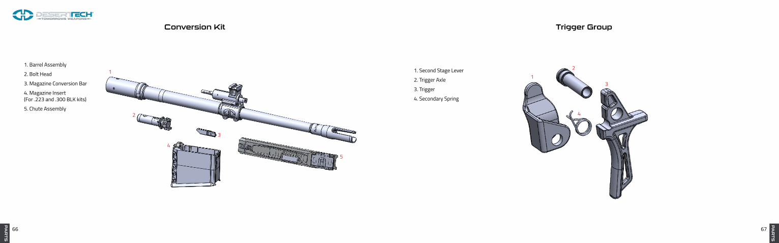
1. Barrel Assembly
2. Bolt Head
3. Magazine Conversion Bar
4. Magazine Insert (For .223 and .300 BLK kits)
5. Chute Assembly
1
2
3
4
5
Conversion Kit Trigger Group
12
3
4
1. Second Stage Lever
2. Trigger Axle
3. Trigger
4. Secondary Spring
PA
RT
S

68 69
PA
RT
S
Sear Assembly Semi-Automatic
1
2
3
4
5
6
7
8
9
1011
1. Hammer
5. Sear
2. Hammer Spring
6. Sear Bushing
3. Sear Axle Pin
7. Sear Housing
4. Sear Spring
8. Hammer Catch
9. Hammer Catch Spring
10. Sear Housing Pin (3)
11. Semi Auto Sear Housing Pin
PA
RT
S
Sear Assembly Automatic
1
2 3
45
67
8
9
10
11
1. Hammer Spring
5. Sear
2. Hammer
6. Sear Spring Right
3. Sear Spring Left
7. Sear Axle Pin
4. Auto Sear
8. Hammer Catch
9. Hammer Catch Spring
10. Auto Sear Housing
11. Sear Housing Pin (4)

70 71
Desert Tech Reflex Optic (DTRO) and DTRO Mount
1
2
3
4
5
6
7
1. DTRO Screws (2)
5. DTRO Mount
2. DTRO
6. DTRO Rail Mount Screw
3. Battery
7. DTRO Rail Mount Nut
4. DTRO Seal Plate
DESERT TECH WARRANTY POLICY
-Desert Tech warrants to the initial retail purchaser that for three (3) years from the date of purchase, your Desert Tech SRS A-1, SRS A-1 Covert, HTI, MDR, including the chassis, conversion kits, scope mounts, muzzle brakes and magazines will be free from manufacturing defects in workmanship and/or material.
-Desert Tech warrants to the initial retail purchaser that your Desert Tech Sound Suppressor will be free from defects in workmanship and/or material for a LIMITED LIFETIME.
-This warranty is null and void if the firearm has been misused, damaged (by accident or otherwise), fired with hand loaded, reloaded or improper ammunition, fired with an obstruction in the barrel, damaged through failure to provide reasonable and necessary maintenance as described in the manual accompa-nying the firearm, or if unauthorized repair or any alteration, including of a cosmetic nature, has been performed on the firearm. This limited warranty does not apply to normal wear and tear of any parts.
-Desert Tech is not responsible for any required BATFE taxes or fees.
-Warranty does not cover third-party products. Third-party product warranties must be pursued directly through the product manufacturer.
-Product registration must be completed online by the original owner within 30 days of the purchase date in order to make a claim under this warranty. In the event of an incomplete registration, the owner must provide proof of purchase in the form of a Dealer Invoice.
-Any NFA item (I.E. Suppressor, Short-Barreled Rifle or Machine Gun) to be returned must be accompanied by a copy of its corresponding Form 3, 4, 5, or 9. The Form must be packaged inside the box with the NFA item. If the proper form is not included, the product will be returned to sender.
-If a valid claim is made within the warranty period and is shipped to the Desert Tech service center, the product will be repaired or replaced (at our discretion) free of charge.
PA
RT
S

72 73
LIMITATION OF LIABILITY
No part of this document may be copied, reproduced, or transmitted by any means, for any purpose without permission from Desert Tech LLC.
All images and text 2008-2017 DT LLC
The liability of Desert Tech LLC. for any and all losses and/or damage to the purchase shall in no event exceed the purchase price of the rifle. In no event shall Desert Tech LLC. be liable for incidental or consequential damage. User
assumes all risks and liabilities arising from the use of this product.
Notes:

74 75
Notes: Notes: