Description of the unit - Swegon handling units/SILVER C version F... · Description of the unit...
62
20171101 We reserve the right to alter specifications. SILVER C 155 Complements and accessories Unit section ......................................................................................................................156 Air recirculation section, TCBRS ................................................................................................................. 156 Solutions for fire bypass ............................................................................................................................. 157 Duct crossover section ................................................................................................................................ 159 Multi section ............................................................................................................................................... 160 Duct accessories ...............................................................................................................162 Uninsulated ................................................................................................................................................. 162 In insulated casing ..................................................................................................................................... 182 Roof and wall hoods........................................................................................................209 Component box ...............................................................................................................210 Outdoor installation ........................................................................................................211 Mechanical equipment ....................................................................................................212 Contents
Transcript of Description of the unit - Swegon handling units/SILVER C version F... · Description of the unit...
20171101 We reserve the right to alter specifi cations.
SILVER C
155
Complements and accessories
Unit section ......................................................................................................................156Air recirculation section, TCBRS .................................................................................................................156Solutions for fi re bypass .............................................................................................................................157Duct crossover section ................................................................................................................................159Multi section ...............................................................................................................................................160
Duct accessories ...............................................................................................................162 Uninsulated .................................................................................................................................................162
In insulated casing .....................................................................................................................................182
Roof and wall hoods ........................................................................................................209
Component box ...............................................................................................................210
Outdoor installation ........................................................................................................211
Mechanical equipment ....................................................................................................212
Contents

SILVER C
We reserve the right to alter specifi cations. 20171101156
H10
0
LB
Complements and Accessories
Unit sectionsTCBR Air recirculation sectionThe air recirculation section is an extra unit section that has damper in the intermediate level.
The air recirculation section is available for the size 011 and larger SILVER C RX, PX and CX units. The air recir-culation section is also available for SILVER C RX/PX size 004-008 in split version.
Included in the delivery: Air recirculation section with mounted dampers (24 V damper actuators are available as an accessories).
Delivery version: Sizes 004-080: The air recirculation section is fi tted to at least one of the other unit sections, see the section entitled: Air Handling Unit/Delivery Confi guration RX/PX/CX, sizes 004-080.
Size 120: The air recirculation section is supplied as an individual item in two sections.
Work to be carried out at the building site: Sizes 004-080: Fitting together/splitting of unit sections to the extent required.
Size 120: Assembly of the air recirculation section to be-come one unit. The air recirculation section is then fi tted together with the other unit sections.
Operation: Recirculation, on/off: Can be used when it is desirable to heat an unoccupied room with recirculated air; an economic solution for e.g. factory buildings, shopping centres, etc.
Recirculation, modulating: Can be used for the demand-controlled and economical operation of fans, heating and cooling, especially in buildings in which the load condi-tions vary.
Depending on the version, the damper can be mounted in the upper or lower level (for SILVER C size 120 the damper is always mounted in the upper level).
For SILVER C B H L kg004/005 825 920 400 50
007/008 995 1085 400 57
011/012 1199 1295 565 90
014/020 1400 1551 565 103
025/030 1600 1811 565 118
035/040 1990 2159 565 142
050/060 2318 2288 565 168
070/080 2637 2640 565 195
100/120 3340 3340 1070 547
Recirculation, on/off.Extract air fan stopped, outdoor air and exhaust air dampers fully closed, damper in the air recircu-
lation section fully open.
Normal operation.
Outdoor air Supply airRecirculation, modulating.
Supply air fan runs at higher speed, outdoor air damper and air recirculation section open when-
ever required.
Extract air Exhaust air
For location/design of base beams, see the corresponding AHU size.

20171101 We reserve the right to alter specifi cations.
SILVER C
157
Complements and accessories
Unit sections Solutions for fi re bypassThe air bypass section is used when you want the extract air to bypass the heat exchanger and fi lter, e.g. as a com-ponent in a system for smoke extraction. See the example for respective variants/sizes. The fans of the air handling unit are tested for, and can manage operation for one hour at 70°C.
The bypass section is available for SILVER C RX/PX size 011-080. The bypass section is also available for SILVER C RX/PX size 004-008 in split version.
Solution for fi re bypass (upward) for SILVER C PX 004-080.
Necessary components required (apart from SILVER C units):The TCBP air bypass section is supplied fi tted together with at least one of the other unit sections, see the section entitled: Description of the Air Handling Unit/Delivery Confi guration RX/PX/CX, sizes 004-080.The required splitting/fi tting together of unit sections is performed at the building site.
Extra dampers may be required depending on the application.Should be controlled via TRITON control and supervisory unit or the like.
Solution for fi re bypass (rear, inspection side or upward) for SILVER C PX 004-040.
Necessary components required (apart from SILVER C units):The TCBP air bypass section is fi tted together with at least one of the other unit sections, see the section entitled: Description of the Air Han-dling Unit/Delivery Confi guration RX/PX/CX, sizes 004-080. Required splitting/fi tting together of unit sections is performed at the building site.Extra dampers may be required depending on the application.Should be controlled via TRITON control and supervisory unit or the like.
SILVER C RX, sizes 004-080 SILVER C PX, sizes 004-040
TCBP
Intake, upward
TCBP
Intake: rear or inspection side

SILVER C
We reserve the right to alter specifications. 20171101158
H10
0
L
P
O
Q
N
B
H10
0
L
J K
B
G I
For SILVER C
B H L G I J K kg
004/005 825 920 400 500 140 300 30 42
007/008 995 1085 400 650 150 300 30 49
011/012 1199 1295 565 1000 100 400 82.5 87
014/020 1400 1551 565 1000 200 400 82.5 103
025/030 1600 1811 565 1200 200 400 82.5 112
035/040 1990 2159 565 1400 295 400 82.5 123
050/060 2318 2288 565 1600 359 400 82,5 168
070/080 2637 2640 565 1800 418,5 400 82,5 246
Complements and accessories
Unit sections
Air bypass section, TCBP, intake upward
For SILVER C
B H L N O P Q kg
004/005 825 920 400 77 300 300 30 47
007/008 995 1085 400 130 300 300 30 56
011/012 1199 1295 565 110 500 400 82.5 70
014/020 1400 1551 565 110 500 400 82.5 85
025/030 1600 1811 565 100 600 400 82.5 96
035/040 1990 2159 565 110 800 400 82.5 123
Air bypass section, TCBP-xxxx, rear intake or on inspection side (SILVER C PX)
Placement/design of the base beam, see the equivalent size of the SILVER C air handling unit.
Placement/design of the base beam, see the equivalent size of the SILVER C air handling unit.
20171101 We reserve the right to alter specifi cations.
SILVER C
159
Complements and accessories
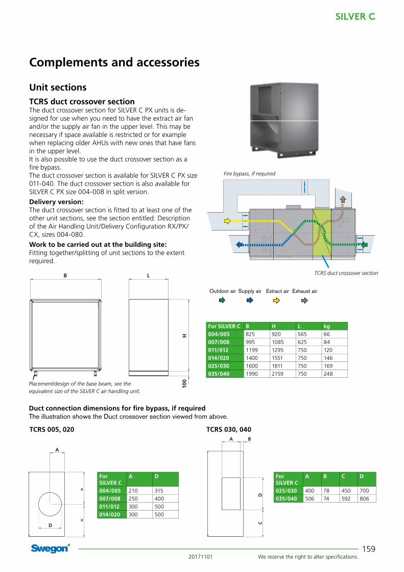
Unit sections TCRS duct crossover sectionThe duct crossover section for SILVER C PX units is de-signed for use when you need to have the extract air fan and/or the supply air fan in the upper level. This may be necessary if space available is restricted or for example when replacing older AHUs with new ones that have fans in the upper level. It is also possible to use the duct crossover section as a fi re bypass.The duct crossover section is available for SILVER C PX size 011-040. The duct crossover section is also available for SILVER C PX size 004-008 in split version.
Delivery version: The duct crossover section is fi tted to at least one of the other unit sections, see the section entitled: Description of the Air Handling Unit/Delivery Confi guration RX/PX/CX, sizes 004-080.
Work to be carried out at the building site: Fitting together/splitting of unit sections to the extent required.
Fire bypass, if required
TCRS duct crossover section
Outdoor air Supply air Extract air Exhaust air
Duct connection dimensions for fi re bypass, if requiredThe illustration shows the Duct crossover section viewed from above.
H10
0
LB
For SILVER C B H L kg004/005 825 920 565 66
007/008 995 1085 625 84
011/012 1199 1295 750 120
014/020 1400 1551 750 146
025/030 1600 1811 750 169
035/040 1990 2159 750 248
TCRS 030, 040TCRS 005, 020
Placement/design of the base beam, see the equivalent size of the SILVER C air handling unit.
==
A
D
DC
A B
==
A
D
DC
A B
For SILVER C
A D
004/005 210 315
007/008 250 400
011/012 300 500
014/020 300 500
For SILVER C
A B C D
025/030 400 78 450 700
035/040 506 74 592 806

SILVER C
We reserve the right to alter specifi cations. 20171101160
Complements and accessories
Unit sections
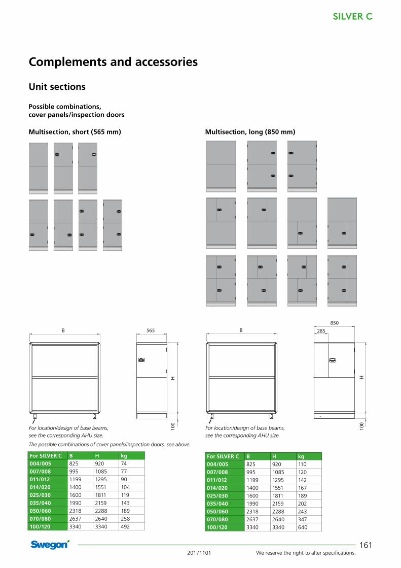
TCFE multisectionThe multisection is an extra unit section, available in two lengths, with intermediate deck and optional combina-tions of cover panels/inspection doors on the inspection side, see illustrations on the next page. The cover panels are easy to dismantle.
Up to two multisections can be used in one air handling unit.
The multisection is available for the size 011 and larger SILVER C RX, PX and CX units. The multisection is also available for SILVER C RX/PX size 004-008 in split version. The multisection can be located between the other unit sections of the SILVER C unit. See example below.
The multisection is available, as a special version, with installed accessories from the factory, for example an air heater/air cooler, dampers, etc..
Delivery version: Sizes 004-080: The multisection is fi tted to at least one of the other unit sections, see the section entitled: Descrip-tion of the Air Handling Unit/Delivery Confi guration RX/PX/CX, sizes 004-080.
Size 120: The multisection is supplied as an individual item in two sections.
Work to be carried out at the building site: Sizes 004-080: Fitting together/splitting of unit sections to the extent required.
Size 120: Assembly of the multisection to become one unit. The multisection is then fi tted together with the other unit sections.
Supply air
Heat exchanger section
Up to two multisections can be used for one air handling unit. The illustration shows possible locations of the multsection.
ExampleUnit section containing extract air fan and supply air fi lter
Unit section containing supply air fan and extract
air fi lter
20171101 We reserve the right to alter specifications.
SILVER C
161
H10
0
285850
B
For SILVER C B H kg004/005 825 920 74
007/008 995 1085 77
011/012 1199 1295 90
014/020 1400 1551 104
025/030 1600 1811 119
035/040 1990 2159 143
050/060 2318 2288 189
070/080 2637 2640 258
100/120 3340 3340 492
H10
0
565B
Complements and accessories
Unit sections
The possible combinations of cover panels/inspection doors, see above.
For SILVER C B H kg004/005 825 920 110
007/008 995 1085 120
011/012 1199 1295 142
014/020 1400 1551 167
025/030 1600 1811 189
035/040 1990 2159 202
050/060 2318 2288 243
070/080 2637 2640 347
100/120 3340 3340 640
Possible combinations, cover panels/inspection doors
Multisection, short (565 mm) Multisection, long (850 mm)
For location/design of base beams, see the corresponding AHU size.
For location/design of base beams, see the corresponding AHU size.

SILVER C
We reserve the right to alter specifications. 20171101162
Complements and accessories
Common for duct accessoriesThe duct accessories must be positioned outside the SILVER C unit in the ductwork. The unique Wing+ fans in the SILVER C air handling unit also make it possible to connect duct accessories directly to the SILVER C unit's duct connections without pressure losses or non-uniform air distribution.
SILVER C with standard end connection panel: The duct accessories for SILVER C, sizes 004/005, 007/008 and 011/012 are fitted with a rubber ring seal.
The duct accessories for SILVER C, sizes 014/020, 025/030, 035/040, 050/060, 070/080 and 100/120 are equipped with connection frames for slip-clamp jointing (slip-clamps must be ordered separately).
Type METU connection frames are available as acces-sories. Insulating, if required, must be done at the site.
SILVER C with full face connection frames: Full face connection frames are available as acces-sories for further reduction of the pressure drop in the ventilation system. See the section on Mechanical equipment.
The duct accessories are equipped with connection frame for slip-clamp jointing (slip clamps must be or-dered separately). Insulating, if required, must be done at the site.
Other particulars for sizing can be obtained by using the AHU Design air handling unit selection program.
Duct accessories, uninsulated

20171101 We reserve the right to alter specifications.
SILVER C
163
TBSA damperThe TBSA 000-031, 000-040, 060-030 and 080-040 dampers are used as shut-off dampers or boosting damp-ers. Other sizes can also be used for other applications.
Shut-off dampers are normally used if the air handling unit is idle during some period, for example at night, or if an air heater for hot water without anti-frost bursting protection is used.
Can be mounted in a horizontal or vertical duct.
The damper can be selected without damper actuator or complete with damper actuator for 24 V. The actuator can be selected with spring return or on/off actuation. TBSA 000-050 and TBSA 100-040 – 250-080 are also available with an actuator of modulating type with spring return.
Technical dataCircular dampers made of galvanised sheet steel, rectan-gular dampers made of aluminium-zinc plated sheet steel. Tightness class 3 to EN 1751.
InstallationConnect the control system and power supply wiring to the damper actuator.
Complements and accessories
SILVER C with standard end connection panel: TBSA 000-031, matches SILVER C, sizes 004, 005TBSA 000-040, matches SILVER C, sizes 007, 008TBSA 000-050, matches SILVER C, sizes 011, 012
SILVER C with standard end connection panel: TBSA 100-040, matches SILVER C, sizes 014, 020TBSA 120-050, matches SILVER C, sizes 025, 030TBSA 140-060, matches SILVER C, sizes 035, 040TBSA 160-080, matches SILVER C, sizes 050, 060TBSA 180-100, matches SILVER C, sizes 070, 080TBSA 240-120, matches SILVER C, sizes 100, 120 (for air intake resp. fan outlet for forward air discharge)TBSA 250-080, matches SILVER C, sizes 100, 120 (for fan outlet for upward air discharge)
SILVER C with full face connection frame (accessory TBXZ): TBSA 060-030, matches SILVER C, sizes 004, 005 TBSA 080-040, matches SILVER C, sizes 007, 008 TBSA 100-040, matches SILVER C, sizes 011, 012 TBSA 120-050, matches SILVER C, sizes 014, 020 TBSA 140-060, matches SILVER C, sizes 025, 030 TBSA 160-080, matches SILVER C, sizes 035, 040 TBSA 180-100, matches SILVER C, sizes 050, 060 TBSA 240-120, matches SILVER C, sizes 070, 080
TBSA A B kg
2-000-031 Ø 315 140 5
2-000-040 Ø 400 210 7
2-000-050 Ø 500 210 8
TBSA A B C D H kg4-060-030 300 640 600 220 340 10
4-080-040 400 840 800 220 440 15
5-100-040 400 1040 1000 110 440 12
4-120-050 500 1240 1200 220 540 25
4-140-060 600 1440 1400 220 640 32
4-160-080 800 1640 1600 220 840 42
4-180-100 1000 1840 1800 220 1040 63
4-240-120 1200 2440 2400 220 1240 105
4-250-080 800 2540 2500 220 840 93
���
��
����
Duct accessories, uninsulated

SILVER C
We reserve the right to alter specifications. 20171101164
Complements and accessories
TBDA Unit sound attenuatorTBDA 000-031, 000-040 and 000-050The TBDA 000-031, 000-040 and 000-050 sound at-tenuators are circular sound attenuators for the SILVER C in sizes 004–012 with standard end connection panel and are intended for installation in the ductwork.
Technical dataGalvanized sheet steel.
Sound attenuating material consisting of 100 mm thick long-fibred glass wool slabs that offer excellent sound attenuation, especially in the mid-frequencies. Glass wool covered with a layer of EUROLON that withstands sub-stantially higher air velocities and mechanical strain than staple fibre. Sound attenuating material covered with perforated sheet steel outside the EUROLON layer.
InstallationProvision for inspection and cleaning must be guaranteed.
L
BH
TBDA B H L kg1-000-031 315 520 915 19,5
1-000-040 400 600 1200 29,5
1-000-050 500 700 1200 63
SILVER C with standard end connection panel:TBDA 000-031, matches SILVER C, sizes 004, 005 TBDA 000-040, matches SILVER C, sizes 007, 008TBDA 000-050, matches SILVER C, sizes 011,012
Duct accessories, uninsulated

20171101 We reserve the right to alter specifications.
SILVER C
165
Complements and accessories
TBDA Unit sound attenuatorTBDA 060-030 to 240-120The TBDA 060-030 to 240-120 sound attenuators for the SILVER C in sizes 004–120 are rectangular and are intended for installation in the ductwork or directly to air handling units with standard end connection panel or full face connection frame.
Technical dataGalvanized sheet steel.
Sound absorption material of type Cleanolon-AL. Cleano-lon-AL consists of mineral wool covered with perforated aluminium foil. Type approved with regard to suitability for cleaning, emissions and fibre entrainment. The mate-rial conforms to the provisions of Surface Layer Class 1 (the highest class).
InstallationProvision for inspection and cleaning must be guaranteed.
H
B
D L
TBDA-1-160-080 TBDA-1-180-100
H
B L
SILVER C with standard end connection panel: TBDA 100-040, matches SILVER C, sizes 014, 020 TBDA 120-050, matches SILVER C, sizes 025, 030 TBDA 140-060, matches SILVER C, sizes 035, 040 TBDA 240-120, matches SILVER C, sizes 100, 120
SILVER C with full face connection frame (accessory TBXZ): TBDA 060-030, matches SILVER C, sizes 004, 005 TBDA 080-040, matches SILVER C, sizes 007, 008 TBDA 100-040, matches SILVER C, sizes 011, 012 TBDA 120-050, matches SILVER C, sizes 014, 020 TBDA 140-060, matches SILVER C, sizes 025, 030 TBDA 240-120, matches SILVER C, sizes 070, 080
TBDA-1060-030 TBDA-1-080-040 TBDA-1-100-040 TBDA-1-120-050 TBDA-1-140-060 TBDA-1-240-120
SILVER C with standard end connection panel: TBDA 160-080, matches SILVER C, sizes 050, 060 TBDA 180-100, matches SILVER C, sizes 070, 080
SILVER C with full face connection frame (accessory TBXZ): TBDA 160-080, matches SILVER C, sizes 035, 040 TBDA 180-100, matches SILVER C, sizes 050, 060
TBDA B H L kg1-060-030 600 300 650 13
1-080-040 800 400 650 22
1-100-040 1000 400 650 26
1-120-050 1200 500 650 33
1-140-060 1400 600 650 39
1-240-120 2400 1200 1250 180
TBDA B D H L kg1-160-080 1800 1600 800 650 72
1-180-100 2000 1800 1000 1250 115
Duct accessories, uninsulated

SILVER C
We reserve the right to alter specifications. 20171101166
Complements and accessories
TBLA Air heater, for hot waterThe TBLA air heater uses hot water as the heating me-dium for post-heating the supply air.
The air heater can be installed for horizontal or vertical airflow.
The TBLA air heater, capacity variant 1, is available with Thermo Guard anti-frost tension protection.
Technical dataUninsulated casing made of galvanized sheet steel.
Finned-tube heat exchangers fabricated of copper tubes and profiled aluminium fins. The headers and the pipe-work to the water connections are made of copper. The male threaded pipe connections are made of brass.
The TBLA air heater is available in two capacity variants. Capacity variant 2 produces the highest capacity.
All the air heaters are equipped with individual plugs for venting and drainage. A separate connection is provided for an anti-frost monitor sensor.
Valve setThe TBVA Valve set consisting of a 2(3)-way valve includ-ing actuator can be ordered.
Extra accessoriesA circulation pump is used for guaranteeing the frost guard function, if air heaters without anti-frost burst protection are used. Supplied with T coupling, non-return valve and adjustment valve.
InstallationProvision for inspection and cleaning must be guaranteed.Electrical connection.
Installation principle with Thermo Guard
Installation principle without Thermo Guard
T piece
Anti-frost sensor
Shut-off valve
Heating water
Shut-off valve
2(3)-way valve
Commission-ing valve
Non-return valve
Applicable to TBLA 000-031 000-040, 000-050 060-030 and 080-040
Anti-freeze monitor sensor. Applicable to TBLA 100-040 to 240-120
Secondary pump
ThermoGuard
Swegon
Thermo Guard con-nection
T piece
Anti-frost sensor
Shut-off valve (must not be closed if freezing is likely – to relieve pressure).
Pressure limiting device, if required
Heating water
Shut-off valve
Regulationvalve
1) The anti-frost sensor for the TBLA sizes 000-031, 000-040, 000-050, 060-030 and 080-040 should be fitted to a T-piece on the return pipework and for the TBLA sizes 000-040 to 240-120 in the connection on the air heater.
Duct accessories, uninsulated

20171101 We reserve the right to alter specifications.
SILVER C
167
H
G
60 60300
A
BF
SILVER C with standard end connection panel: TBLA 000–031, matches SILVER C, sizes 004, 005TBLA 000–040 matches SILVER C, sizes 007, 008TBLA 000–050 matches SILVER C, sizes 011, 012
Without Thermoguard
With Thermoguard
TBLA A B H R kg* 4-000-031-1-1 Ø 315 488 428 DN 15 14
4-000-040-1-1 Ø 400 588 528 DN 15 19
4-000-050-1-1 Ø 500 688 628 DN 15 24
* Excluding water.
Complements and accessories
50
H
60 60300
A
B
210 C E
H
50 100B
A60
Conn. R male
threads.
SILVER C with standard end connection panel: TBLA 000–031, matches SILVER C, sizes 004, 005TBLA 000–040 matches SILVER C, sizes 007, 008TBLA 000–050 matches SILVER C, sizes 011, 012
* Excluding water.
Conn. R male
threads.
Duct accessories, uninsulated
TBLA A B F G H R kg* 6-000-031-2-1 Ø 315 490 225 192 405 DN20 15
6-000-040-2-1 Ø 400 590 277 250 500 DN25 18
6-000-040-2-2 Ø 400 590 277 250 500 DN25 20
6-000-050-2-1 Ø 500 690 327 300 600 DN25 23
6-000-050-2-2 Ø 500 690 327 300 600 DN25 31

SILVER C
We reserve the right to alter specifications. 20171101168
TBLA A B C E H L R F kg* 4-060-030-2-1 300 728 600 80 338 148 DN15 47 6
4-060-030-2-2 300 728 600 80 338 148 DN15 47 7
4-080-040-2-1 400 928 800 80 438 148 DN15 47 8
4-080-040-2-2 400 928 800 80 438 148 DN15 47 10
4-100-040-2-1 400 1119 1000 90 438 148 DN15 40 14
4-100-040-2-2 400 1126 1000 90 438 170 DN20 40 18
4-120-050-2-1 500 1319 1200 90 538 148 DN15 40 17
4-140-060-2-1 600 1526 1400 90 638 148 DN20 40 23
Without Thermoguard
* Excluding water.
Conn.
R male
threads.
Conn.
R male
threads.
Without Thermoguard
* Excluding water.
Complements and accessories
SILVER C with standard end connection panel: TBLA 100-040, matches SILVER C, sizes 014, 020TBLA 120–050, matches SILVER C, sizes 025, 030TBLA 140-060, matches SILVER C, sizes 035, 040TBLA 160-080, matches SILVER C, sizes 050, 060TBLA 180-100, matches SILVER C, sizes 070, 080TBLA 240-120, matches SILVER C, sizes 100, 120
SILVER C with full face connection frame (accessory TBXZ): TBLA 100–040, matches SILVER C, sizes 011, 012TBLA 120–050, matches SILVER C, sizes 014, 020TBLA 140-060, matches SILVER C, sizes 025, 030TBLA 160-080, matches SILVER C, sizes 035, 040TBLA 180-100, matches SILVER C, sizes 050, 060TBLA 240-120, matches SILVER C, sizes 070, 080
SILVER C with standard end connection panel: TBLA 100-040, matches SILVER C, sizes 014, 020TBLA 120–050, matches SILVER C, sizes 025, 030TBLA 140-060, matches SILVER C, sizes 035, 040
SILVER C with full face connection frame (accessory TBXZ): TBLA-1-060-030, matches SILVER C, sizes 004, 005 TBLA-1-080-040, matches SILVER C, sizes 007, 008 TBLA-1-100-040, matches SILVER C, sizes 011, 012 TBLA-1-120-050, matches SILVER C, sizes 014, 020 TBLA-1-140-060, matches SILVER C, sizes 025, 030
TBLA A B C E H L R F kg* 4-100-040-2-3 400 1250 1000 85 605 300 DN25 125 53
4-120-050-2-2 500 1590 1200 85 700 300 DN20 195 72
4-120-050-2-3 500 1590 1200 85 755 300 DN32 195 78
4-140-060-2-2 600 1815 1400 85 840 300 DN25 208 94
4-140-060-2-3 600 1850 1400 85 880 300 DN32 225 101
4-160-080-2-1 800 2210 1600 85 1020 300 DN25 280 97
4-160-080-2-2 800 2210 1600 85 1020 300 DN32 274 114
4-160-080-2-3 800 2210 1600 85 1020 300 DN50 259 127
4-180-100-2-1 1000 2530 1800 85 1220 300 DN25 340 127
4-180-100-2-2 1000 2530 1800 85 1220 300 DN32 329 152
4-180-100-2-3 1000 2530 1800 85 1220 300 DN50 319 168
4-240-120-2-1 1200 3240 2400 85 1520 300 DN40 389 187
4-240-120-2-2 1200 3240 2400 85 1520 300 DN50 374 235
4-240-120-2-3 1200 3240 2400 85 1520 300 DN65 358 264
Duct accessories, uninsulated

20171101 We reserve the right to alter specifications.
SILVER C
169
Complements and accessories
30 L C E
H
30 75B
A60
TBLACapacity variant 1
B H L A C E R kg*4-060-030-1-1 789 381 180 300 600 125 DN15 13
4-080-040-1-1 989 481 180 400 800 125 DN15 18
With Thermoguard
SILVER C with full face connection frame (accessory TBXZ): TBLA 060-030, matches SILVER C, sizes 004, 005 TBLA 080-040, matches SILVER C, sizes 007, 008
Conn.
R male
threads.
* Excluding water.
TBLACapacity variant 1
B H L A C E F R kg*4-100-040 1213 580 210 400 1000 100 100 DN15 50
4-120-050 1568 680 210 500 1200 100 100 DN20 68
4-140-060 1818 820 210 600 1400 100 100 DN20 90
4-160-080 2173 1020 300 800 1600 100 254 DN25 121
4-180-100 2493 1195 300 1000 1800 100 310 DN32 159
4-240-120 3154 1510 300 1200 2400 100 356 DN50 195
With Thermoguard
SILVER C with standard end connection panel: TBLA 100-040, matches SILVER C, sizes 014, 020TBLA 120–050, matches SILVER C, sizes 025, 030TBLA 140-060, matches SILVER C, sizes 035, 040TBLA 160-080, matches SILVER C, sizes 050, 060TBLA 180–100, matches SILVER C, sizes 070, 080TBLA 240-120, matches SILVER C, sizes 100, 120
SILVER C with full face connection frame (accessory TBXZ):TBLA 100-040, matches SILVER C, sizes 011, 012TBLA 120–050, matches SILVER C, sizes 014, 020TBLA 140-060, matches SILVER C, sizes 025, 030TBLA 160-080, matches SILVER C, sizes 035, 040TBLA 180–100, matches SILVER C, sizes 050,060TBLA 240-120, matches SILVER C, sizes 070, 080
Conn.
R male
threads.
50
H
60 60300
A
B 25
L C E
H
50 FB
A60
* Excluding water.
Duct accessories, uninsulated

SILVER C
We reserve the right to alter specifications. 20171101170
Air heater TBCE/TBRE, electricAir heater TBCE/TBRE is used for reheating of the supply air or for certain preheating needs of outdoor air.
The air heater can be installed for horizontal or vertical airflow.
The integrated thyristor is controlled via signals 0 - 10V. The air heater is equipped with four, five or six series-coupled overheating protections.
Technical dataUninsulated casing made of galvanized sheet steel.
Air heater TBCE/TBRE is available in several capacity vari-ants.
The electrical equipment conforms to the provisions of Degree of Protection IP44.
The air heater is approved for operating temperatures, in the surroundings and the air stream, from -25°C to +40°C.
InstallationTBCE 000-031, 000-040 and 000-050: The end panel on the connection side can be dismantled for inspection and connection.
For air heaters with circular duct connection, the distance from or to a duct bend, damper, filter or the like, should be at least the distance that is equivalent to double (triple recommended) the diameter of the duct. For air heaters with a rectangular duct connection the distance should be at least the equivalent to the air heater’s diagonal dimension (double recommended), i.e. from corner to corner in the duct section of the air heater. Otherwise there is risk that the airflow through the air heater will be non-uniform, involving risk that the overheat protection device will trip.
Electrical connection. Power must be supplied directly from the electrical distribution box. An isolating switch is recommended.
Complements and accessories
Duct accessories, uninsulated
TBCE
TBRE

20171101 We reserve the right to alter specifications.
SILVER C
171
SILVER C with standard end connection frame: TBCE 000-031, corresponds to SILVER C sizes 004, 005TBCE-000-040, corresponds to SILVER C sizes 007, 008TBCE-000-050, corresponds to SILVER C sizes 011, 12
TBCE ø A B C D E kg-1-000-031-002-2 315 375 293 405 344 8
-1-000-031-004-1 315 375 293 405 344 9
-1-000-031-004-2 315 375 293 405 344 9
-1-000-031-007-1 315 500 418 405 344 10.5
-1-000-031-007-2 315 500 418 405 344 10.5
-1-000-031-010-1 315 500 418 405 344 11.5
-1-000-031-010-2 315 500 418 405 344 11.5
-1-000-040-004-1 400 375 293 490 428 10.5
-1-000-040-004-2 400 375 293 490 428 10.5
-1-000-040-007-1 400 500 418 490 428 12.5
-1-000-040-007-2 400 500 418 490 428 12.5
-1-000-040-012-1 400 630 548 490 428 15
-1-000-040-012-2 400 630 548 490 428 15
-1-000-040-018-1 400 770 688 490 428 19.5
-1-000-040-018-2 400 770 688 490 428 19.5
-1-000-050-006-1 500 375 293 590 528 12.5
-1-000-050-006-2 500 375 293 590 528 12.5
-1-000-050-012-1 500 630 548 590 528 17.5
-1-000-050-012-2 500 630 548 590 528 17.5
-1-000-050-021-1 500 880 798 590 528 26
-1-000-050-021-2 500 880 798 590 528 26
-1-000-050-027-1 500 1150 1068 590 528 33
-1-000-050-027-2 500 1150 1068 590 528 33
Complements and accessories
Duct accessories, uninsulated
ØA
41 41CEB
90
D

SILVER C
We reserve the right to alter specifications. 20171101172
SILVER C with standard end connection frame: TBRE 100-040, corresponds to SILVER C sizes 014, 020TBRE 120-050, corresponds to SILVER C sizes 025, 030TBRE 140-060, corresponds to SILVER C sizes 035, 040TBRE 160-080, corresponds to SILVER C sizes 050, 060 TBRE 180-100, corresponds to SILVER C sizes 070, 080 TBRE 240-120, corresponds to SILVER C sizes 100, 120
SILVER C with full face end connection panel (accessory TBXZ): TBRE 060-030, corresponds to SILVER C sizes 004, 005 TBRE 080-040, corresponds to SILVER C sizes 007, 008 TBRE 100-040, corresponds to SILVER C, size 011, 012TBRE 1200-500 corresponds to SILVER C sizes 014, 020TBRE 1400-600 corresponds to SILVER C, size 025/30TBRE 1600-800 corresponds to SILVER C, size 035/040TBRE 1800-1000 corresponds to SILVER C, size 050/060TBRE 2400-1200 corresponds to SILVER C, size 070/080
TBRE A B C H kg1-060-030 300 600 710 338 15 - 18
1-080-040 400 800 880 438 19 - 25
1-100-040 400 1000 1084 438 22 - 37
1-120-050 500 1200 1285 538 25 - 42
1-140-060 600 1400 1482 638 31 - 51
1-160-080 800 1600 1737 838 38 - 63
1-180-100 1000 1800 2017 1038 48 - 76
1-240-120 1200 2400 2521 1238 59 - 96
Complements and accessories
Duct accessories, uninsulated
21 378 21420 C
B
H A

20171101 We reserve the right to alter specifications.
SILVER C
173
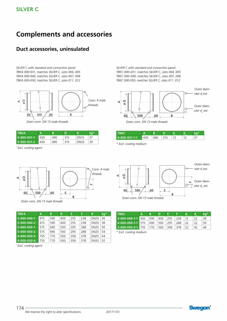
TBKA Air cooler (water), TBKC (direct expansion)The TBKA/TBKC air coolers are used for cooling the sup-ply air with chilled water or evaporative refrigerant as the cooling medium.
The TBKA/TBKC air cooler is available in several capacity variants that cover existing needs for the corresponding size of SILVER C unit.
The air cooler must be installed for horizontal airflow.
Technical dataUninsulated casing made of galvanized sheet steel.
The TBKA/TBKC air coolers are composed of copper tubes and profiled aluminium fins. The TBKA has headers and water connections made of copper/brass, with male connection threads. The TBKC has headers and distributor tubes made of copper. The connections are designed for brazed joints.
Valve setThe TBVA Valve set consisting of a 2(3)-way valve includ-ing actuator can be ordered.
InstallationTBKA/TBKC 000-031, 000-040 and 000-050: The end panel on the connection side can be dismantled for inspection and connection. TBKA/TBKC 060-030 to 240-120: Provision for inspection and cleaning must be guaranteed.Connecting the drainage pipework.Electrical connection.
Complements and accessories
Duct accessories, uninsulated
SILVER C
We reserve the right to alter specifications. 20171101174
50060 60 BA ø D
B50060 60 E
A
F
ø D
50060 60 B
A ø D
SILVER C with standard end connection panel: TBKA 000-031, matches SILVER C, sizes 004, 005TBKA 000-040, matches SILVER C, sizes 007, 008TBKA 000-050, matches SILVER C, sizes 011, 012
Drain conn. DN 15 male threads
Outer diam-
eter du ext.
Outer diam-
eter di ext.
Drain conn. DN 15 male threads
Conn. R male
threads.
* Excl. cooling medium
TBKA A B D R kg* 5-000-031-1 430 490 315 DN15 37
5-000-031-2 430 490 315 DN20 39
TBKC A B D di du kg*4-000-031-1-1 430 490 315 12 12 37
SILVER C with standard end connection panel: TBKC 000–031, matches SILVER C, sizes 004, 005TBKC 000–040, matches SILVER C, sizes 007, 008TBKC 000-050, matches SILVER C, sizes 011, 012
* Excl. cooling agent
Complements and accessories
TBKA A B D E F R kg* 5-000-040-1 475 590 400 255 238 DN20 36
5-000-040-2 475 590 400 255 238 DN20 38
5-000-050-1 575 690 500 295 288 DN25 50
5-000-050-2 575 690 500 295 288 DN25 54
4-000-050-5 755 770 500 358 378 DN25 44
4-000-050-6 755 770 500 358 378 DN32 52
Drain conn. DN 15 male threads
Conn. R male
threads.
* Excl. cooling agent
TBKC A B D E F di du kg*3-000-040-1-1 455 590 400 255 228 12 22 28
4-000-050-1-1 575 690 500 295 288 22 22 50
3-000-050-3-1 755 770 500 358 378 22 42 46
* Excl. cooling medium
B50060 60 E
A
F
ø D
Outer diam-
eter du ext.
Outer diam-
eter di ext.
Drain conn. DN 15 male threads
Duct accessories, uninsulated

20171101 We reserve the right to alter specifications.
SILVER C
175
TBKA A B C E G H R kg*5-060-030-1 300 754 600 47 19 361 DN15 13
5-060-030-2 300 754 600 47 19 361 DN20 15
5-060-030-3 300 754 600 47 19 361 DN20 17
5-080-040-1 400 954 800 47 19 461 DN20 19
5-080-040-2 400 954 800 47 19 461 DN25 22
5-080-040-3 400 954 800 47 19 461 DN25 26
5-100-040-0 400 1225 1000 77 64 527 DN32 52
5-100-040-1 400 1295 1000 148 113 625 DN32 58
5-100-040-2 400 1295 1000 148 113 625 DN32 60
5-100-040-3 400 1295 1000 148 113 625 DN32 64
5-120-040-4** 400 1495 1200 148 113 625 DN40 82
5-120-050-0 500 1425 1200 62 62 623 DN32 70
5-120-050-1 500 1595 1200 198 168 835 DN40 80
5-120-050-2 500 1595 1200 198 168 835 DN50 90
5-120-050-3 500 1595 1200 198 168 835 DN50 100
5-140-050-4** 500 1790 1400 195 168 835 DN50 122
5-140-060-0 600 1625 1400 62 62 723 DN32 91
5-140-060-1 600 1885 1400 243 170 940 DN50 106
5-140-060-2 600 1885 1400 243 170 940 DN50 118
5-140-060-3 600 1885 1400 243 170 940 DN65 134
5-160-060-4** 600 2085 1600 243 170 940 DN65 154
5-160-080-1 800 1794 1600 47 19 846 DN32 66
5-160-080-2 800 2180 1600 290 110 1020 DN50 174
5-160-080-3 800 2180 1600 290 110 1020 DN50 223
5-160-080-4 800 2180 1600 290 110 1020 DN65 211
5-180-100-1 1000 1994 1800 47 19 1051 DN50 88
5-180-100-2 1000 2500 1800 350 110 1220 DN65 232
5-180-100-3 1000 2500 1800 350 110 1220 DN65 228
5-180-100-4 1000 2500 1800 350 110 1220 DN65 250
5-240-120-1 1200 2644 2400 47 19 1256 DN65 138
5-240-120-2 1200 3210 2400 405 160 1520 DN65 309
5-240-120-3 1200 3210 2400 405 160 1520 DN80 406
5-240-120-4 1200 3210 2400 405 160 1520 DN100 454
Drain conn. DN 25 male threads
* Excl. cooling agent** The connection dimensions of the coil are not the same as those of the SILVER C unit. Some form of transition piece must be installed between the air handling unit and the air cooler.
Complements and accessories
Conn. R male
threads.
SILVER C with standard end connection panel: TBKA 100-040, matches SILVER C, sizes 014, 020 TBKA 120-050, matches SILVER C, sizes 025, 030TBKA 140-060, matches SILVER C, sizes 035, 040TBKA 160-080, matches SILVER C, sizes 050, 060TBKA 180-100, matches SILVER C, sizes 070, 080TBKA 240-120, matches SILVER C, sizes 100, 120
SILVER C with full face connection frame (accessory TBXZ): TBKA 060-030, matches SILVER C, sizes 004, 005 TBKA 080-040, matches SILVER C, sizes 007, 008 TBKA 100-040, matches SILVER C, sizes 011, 012 TBKA 120-050, matches SILVER C, sizes 014, 020 TBKA 140-060, matches SILVER C, sizes 025, 030 TBKA 160-080, matches SILVER C, sizes 035, 040 TBKA 180-100, matches SILVER C, sizes 050,060 TBKA 240-120, matches SILVER C, sizes 070, 080
Duct accessories, uninsulated

SILVER C
We reserve the right to alter specifications. 20171101176
240
G
E C
B
H A
Drain conn. DN 25
male threads Ext. conn. to be brazed.
* Excl. cooling agent
TBKC A B C E G H di du kg* 3-100-040-0-1 400 1154 1000 49 19 461 22 28 24
3-100-040-0-2 400 1154 1000 49 19 461 12/16 16/22 25
3-120-050-0-1 500 1394 1200 49 19 561 28 35 33
3-120-050-0-2 500 1394 1200 49 19 561 16/28 22/35 34
3-140-060-0-1 600 1594 1400 49 19 661 28 35 41
3-140-060-0-2 600 1594 1400 49 19 661 22/28 28/35 42
Outer
diameter
du ext.
Outer
diameter
di ext.
Complements and accessories
SILVER C with standard end connection frame: TBKC 100-040, matches SILVER C, sizes 014, 020 TBKC 120-050, matches SILVER C, sizes 025, 030TBKC 140-060, matches SILVER C, sizes 035, 040
SILVER C with full face connection frame (accessory TBXZ): TBKC 100-040, matches SILVER C, sizes 011, 012 TBKC 120-050, matches SILVER C, sizes 014, 020 TBKC 140-060, matches SILVER C, sizes 025, 030
Capacity variant 0
Duct accessories, uninsulated
20171101 We reserve the right to alter specifications.
SILVER C
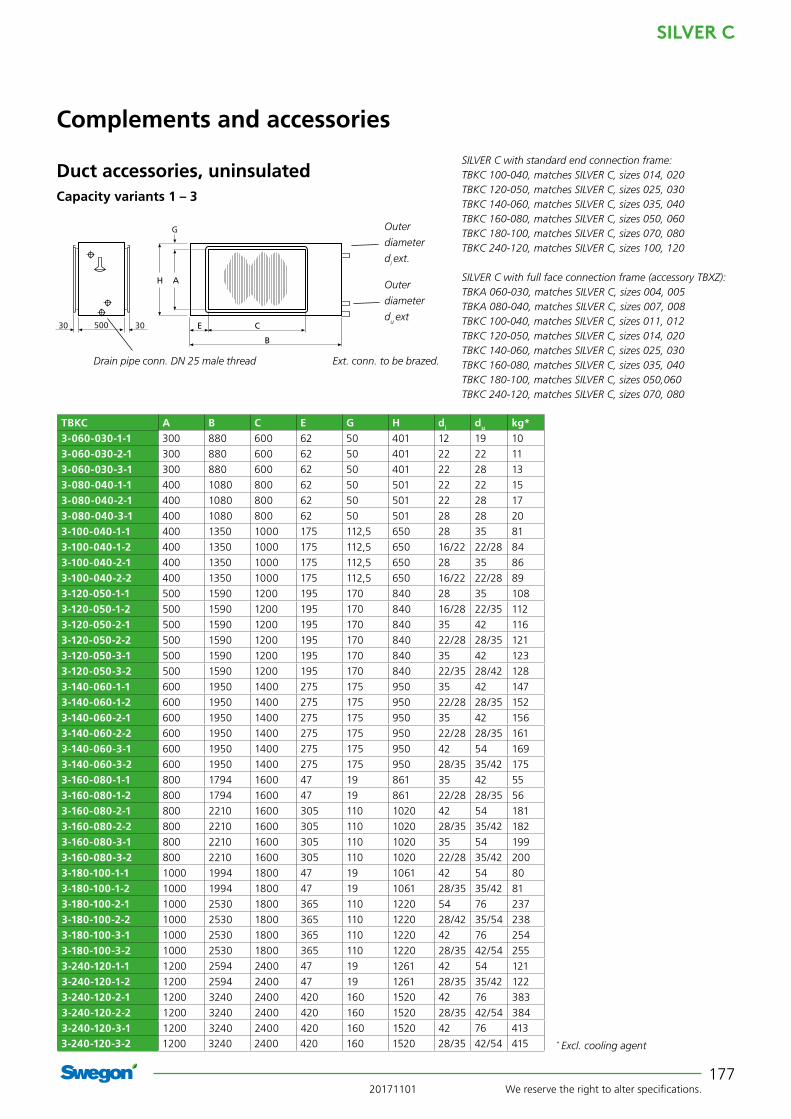
177
500 3030
G
E C
B
H A
SILVER C with standard end connection frame: TBKC 100-040, matches SILVER C, sizes 014, 020 TBKC 120-050, matches SILVER C, sizes 025, 030TBKC 140-060, matches SILVER C, sizes 035, 040TBKC 160-080, matches SILVER C, sizes 050, 060TBKC 180-100, matches SILVER C, sizes 070, 080TBKC 240-120, matches SILVER C, sizes 100, 120
SILVER C with full face connection frame (accessory TBXZ): TBKA 060-030, matches SILVER C, sizes 004, 005 TBKA 080-040, matches SILVER C, sizes 007, 008 TBKC 100-040, matches SILVER C, sizes 011, 012 TBKC 120-050, matches SILVER C, sizes 014, 020 TBKC 140-060, matches SILVER C, sizes 025, 030 TBKC 160-080, matches SILVER C, sizes 035, 040 TBKC 180-100, matches SILVER C, sizes 050,060 TBKC 240-120, matches SILVER C, sizes 070, 080
Capacity variants 1 – 3
TBKC A B C E G H di du kg* 3-060-030-1-1 300 880 600 62 50 401 12 19 10
3-060-030-2-1 300 880 600 62 50 401 22 22 11
3-060-030-3-1 300 880 600 62 50 401 22 28 13
3-080-040-1-1 400 1080 800 62 50 501 22 22 15
3-080-040-2-1 400 1080 800 62 50 501 22 28 17
3-080-040-3-1 400 1080 800 62 50 501 28 28 20
3-100-040-1-1 400 1350 1000 175 112,5 650 28 35 81
3-100-040-1-2 400 1350 1000 175 112,5 650 16/22 22/28 84
3-100-040-2-1 400 1350 1000 175 112,5 650 28 35 86
3-100-040-2-2 400 1350 1000 175 112,5 650 16/22 22/28 89
3-120-050-1-1 500 1590 1200 195 170 840 28 35 108
3-120-050-1-2 500 1590 1200 195 170 840 16/28 22/35 112
3-120-050-2-1 500 1590 1200 195 170 840 35 42 116
3-120-050-2-2 500 1590 1200 195 170 840 22/28 28/35 121
3-120-050-3-1 500 1590 1200 195 170 840 35 42 123
3-120-050-3-2 500 1590 1200 195 170 840 22/35 28/42 128
3-140-060-1-1 600 1950 1400 275 175 950 35 42 147
3-140-060-1-2 600 1950 1400 275 175 950 22/28 28/35 152
3-140-060-2-1 600 1950 1400 275 175 950 35 42 156
3-140-060-2-2 600 1950 1400 275 175 950 22/28 28/35 161
3-140-060-3-1 600 1950 1400 275 175 950 42 54 169
3-140-060-3-2 600 1950 1400 275 175 950 28/35 35/42 175
3-160-080-1-1 800 1794 1600 47 19 861 35 42 55
3-160-080-1-2 800 1794 1600 47 19 861 22/28 28/35 56
3-160-080-2-1 800 2210 1600 305 110 1020 42 54 181
3-160-080-2-2 800 2210 1600 305 110 1020 28/35 35/42 182
3-160-080-3-1 800 2210 1600 305 110 1020 35 54 199
3-160-080-3-2 800 2210 1600 305 110 1020 22/28 35/42 200
3-180-100-1-1 1000 1994 1800 47 19 1061 42 54 80
3-180-100-1-2 1000 1994 1800 47 19 1061 28/35 35/42 81
3-180-100-2-1 1000 2530 1800 365 110 1220 54 76 237
3-180-100-2-2 1000 2530 1800 365 110 1220 28/42 35/54 238
3-180-100-3-1 1000 2530 1800 365 110 1220 42 76 254
3-180-100-3-2 1000 2530 1800 365 110 1220 28/35 42/54 255
3-240-120-1-1 1200 2594 2400 47 19 1261 42 54 121
3-240-120-1-2 1200 2594 2400 47 19 1261 28/35 35/42 122
3-240-120-2-1 1200 3240 2400 420 160 1520 42 76 383
3-240-120-2-2 1200 3240 2400 420 160 1520 28/35 42/54 384
3-240-120-3-1 1200 3240 2400 420 160 1520 42 76 413
3-240-120-3-2 1200 3240 2400 420 160 1520 28/35 42/54 415
Duct accessories, uninsulated
Drain pipe conn. DN 25 male thread Ext. conn. to be brazed.
Outer
diameter
di ext.
Outer
diameter
du ext
Complements and accessories
* Excl. cooling agent

SILVER C
We reserve the right to alter specifications. 20171101178
TBBD Mixing Section The TBBD mixing section is available for the SILVER C SD in sizes 004-080.
The mixing section can be used when it is desirable use recirculated air for completely or partially heating a build-ing while it is unoccupied.
The TBBD consists of a spiral tubular T-piece (sizes 000-031 – 000-050) or a rectangular duct with three connec-tions for slip-clamp jointing (sizes 060-030 – 080-100).
The spiral duct joints (sizes 000-031 – 000-050) in required quantity and the sets of slip clamps (sizes 060-030 – 080-100) respectively are included in the supply.
The mounted damper actuators (24 V) are available as optional extras. These have modulated action.
The mixing section can be ordered with two or three dampers depending on its range of application. See the example on the next page.
Additional equipment required: Supply air handling units should be equipped with an air heater.
Work to be carried out at the building site: Instal-lation the mixing section to the air handling unit/duct. Install dampers for the mixing section or duct Electrical connection. Install insulation conforming to local regula-tions
Complements and accessories
Duct accessories, uninsulated
20171101 We reserve the right to alter specifications.
SILVER C
179
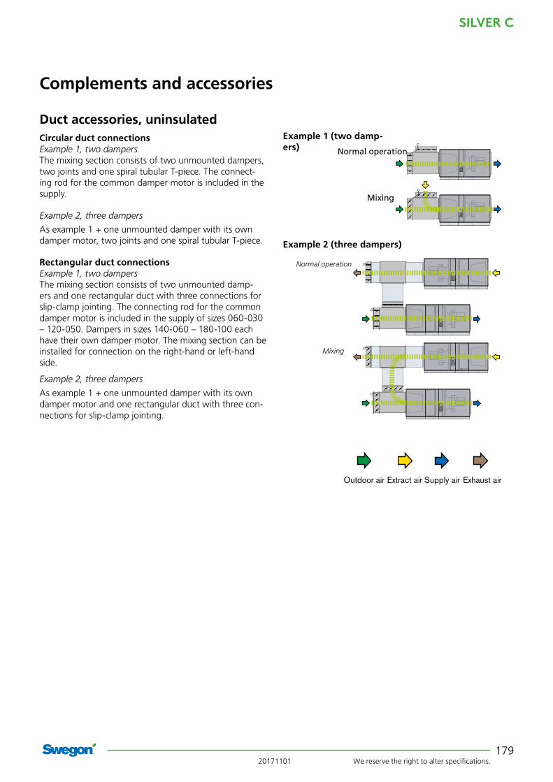
Complements and accessories
Circular duct connectionsExample 1, two dampersThe mixing section consists of two unmounted dampers, two joints and one spiral tubular T-piece. The connect-ing rod for the common damper motor is included in the supply.
Example 2, three dampers
As example 1 + one unmounted damper with its own damper motor, two joints and one spiral tubular T-piece.
Rectangular duct connectionsExample 1, two dampersThe mixing section consists of two unmounted damp-ers and one rectangular duct with three connections for slip-clamp jointing. The connecting rod for the common damper motor is included in the supply of sizes 060-030 – 120-050. Dampers in sizes 140-060 – 180-100 each have their own damper motor. The mixing section can be installed for connection on the right-hand or left-hand side.
Example 2, three dampers
As example 1 + one unmounted damper with its own damper motor and one rectangular duct with three con-nections for slip-clamp jointing.
Outdoor air Extract air Exhaust air Supply air
Normal operation
Mixing
Normal operation
Mixing
Example 1 (two damp-ers)
Example 2 (three dampers)
Duct accessories, uninsulated

SILVER C
We reserve the right to alter specifications. 20171101180
Complements and accessories
øD
øD
L3 L2 L1
H
L1L2
F x G
H
Three dampers
The dimensions of the component parts supplied by Swegon can be read in the sketch to the left.
Two dampers
Three dampers
The dimensions of the component parts supplied by Swegon can be read in the sketch to the left.
SILVER C with standard end connection panel: TBBD 000-031, matches SILVER C, size 004/005 TBBD 000-040, matches SILVER C, size 007/008 TBBD 000-050, matches SILVER C, size 011/012
Two dampers
SILVER C with standard end connection panel: TBBD 100-040, matches SILVER C, size 014/020TBBD 120-050, matches SILVER C, size 025/030TBBD 140-060, matches SILVER C, size 035/040TBBD 160-080, matches SILVER C, size 050/060TBBD 180-100, matches SILVER C, size 070/080
SILVER C with full face connection frame (accessory TBXZ): TBBD 060-030, matches SILVER C, sizes 004, 005 TBBD 080-040, matches SILVER C, sizes 007, 008 TBBD 100–040, matches SILVER C, sizes 011, 012TBBD 120-050, matches SILVER C, sizes 014, 020TBBD 140-060, matches SILVER C, sizes 025, 030TBBD 160-080, matches SILVER C, sizes 035, 040TBBD 180-100, matches SILVER C, sizes 050, 060
TBBD L1 L2 H F x G060-030 420 220 570 300 x 600
080-040 520 220 670 400 x 800
100-040 520 220 670 400 x 1000
120-050 620 220 770 500 x 1200
140-060 720 220 870 600 x 1400
160-080 920 220 1070 800 x 1600
180-100 1120 220 1270 1000 x 1800
TBBD L1 L2 L3 H øD000-031 363 140 140 620 315
000-040 510 180 210 825 400
000-050 552 180 210 930 500
Duct accessories, uninsulated

20171101 We reserve the right to alter specifications.
SILVER C
181
Prefilter, TBFA Pre-filter should be installed in the outdoor air duct and/or the extract air duct.
The pre-filter is used in ventilation systems, in which the extract air and/or the outdoor air is heavily polluted and it is desirable to prevent the fine filter inside the SILVER C unit from becoming clogged after a short period of use.
Technical dataThe TBFA has uninsulated casing made of galvanized sheet steel. Insulated inspection door. The filters are of woven aluminium type or Class G3 com-pact filters.
InstallationProvision for inspection and cleaning must be guaranteed.Install insulation conforming to local regulations
Complements and accessories
TBFA 000-031, matches SILVER C, sizes 004, 005TBFC 000–040, matches SILVER C, sizes 007, 008TBFA 000-050, matches SILVER C, sizes 011, 012
TBFA B D H kg000-031 500 315 500 18
000-040 600 400 600 22
000-050 900 500 600 24
TBFA 100-040, matches SILVER C, sizes 014, 020 TBFA 120-050, matches SILVER C, sizes 025, 030 TBFA 140–060, matches SILVER C, sizes 035, 040TBFA 160-080, matches SILVER C, sizes 050, 060TBFA 180-100, matches SILVER C, sizes 070, 080 TBFA 240-120, matches SILVER C, sizes 100, 120
TBFA A B C H kg100-040 400 1200 1000 600 26
120-050 500 1500 1200 600 36
140-060 600 1800 1400 900 48
160-080 800 2475 1600 1000 59
180-100 1000 2400 1800 1200 68
240-120 1200 3000 2400 1800 140
Outdoor air Extract air Exhaust air Supply air
B 40
C 320
380
HA
50
50
ø D
B 40
320
380
H
50
50
Duct accessories, uninsulated
SILVER C
We reserve the right to alter specifications. 20171101182
Complements and accessories
Common for duct accessories in an insulated casingThe duct accessories are to be positioned outside the SILVER C unit. The unique Wing+ fans in the SILVER C air handling unit also make it possible to connect duct accessories directly to the SILVER C unit's duct connection without pressure losses or non-uniform air distribution.
Duct accessories in an insulated casing must be used if the unit is installed outdoors.
Duct accessories for the SILVER C are equipped with bolted joints and/or expansion-type locking devices for docking them to the air handling unit and/or other duct accessories.
One duct accessory can be mounted on top of another duct accessory.
Other particulars for sizing can be obtained by using the AHU Design air handling unit selection program.
Duct accessories, in insulated casing
20171101 We reserve the right to alter specifi cations.
SILVER C
183
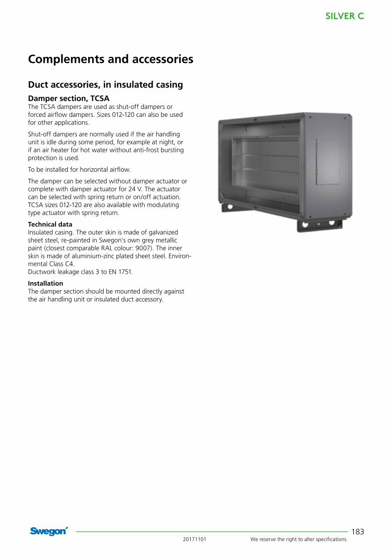
Damper section, TCSAThe TCSA dampers are used as shut-off dampers or forced airfl ow dampers. Sizes 012-120 can also be used for other applications.
Shut-off dampers are normally used if the air handling unit is idle during some period, for example at night, or if an air heater for hot water without anti-frost bursting protection is used.
To be installed for horizontal airfl ow.
The damper can be selected without damper actuator or complete with damper actuator for 24 V. The actuator can be selected with spring return or on/off actuation. TCSA sizes 012-120 are also available with modulating type actuator with spring return.
Technical dataInsulated casing. The outer skin is made of galvanized sheet steel, re-painted in Swegon's own grey metallic paint (closest comparable RAL colour: 9007). The inner skin is made of aluminium-zinc plated sheet steel. Environ-mental Class C4.Ductwork leakage class 3 to EN 1751.
InstallationThe damper section should be mounted directly against the air handling unit or insulated duct accessory.
Complements and accessories
Duct accessories, in insulated casing

SILVER C
We reserve the right to alter specifications. 20171101184
BL
16
52*
H
100
Connection dimensions to duct:TCSA 012 ø 500
TCSA B H L kgEnd connection panel, if required
kg-012 1199 647,5 400 60 13
Duct accessories in the lower duct are always delivered with mounted base beam. Duct accessories in the upper duct are always delivered without base beam.* If several duct accessories are arranged in succession, the end connection panel is supplied only on the duct accessory farthest out facing the ductwork.
Connection dimensions to duct:TCSA 005 ø 315TCSA 008 ø 400
TCSA B H L kgEnd connection panel, if required
kg-005 825 460 400 41 7
-008 995 542,5 400 47 10
Base beam is optional on duct accessories in the lower duct. Duct accessories in the upper duct are always delivered without base beam.* If several duct accessories are arranged in succession, the end connection panel is supplied only on the duct accessory farthest out facing the ductwork.
Complements and accessories
Duct accessories, in insulated casingBL52*
H
100
16
BL
21
52*
H
100
Connection dimensions to duct:TCSA 020 1000 x 400 mmTCSA 030 1200 x 500 mmTCSA 040 1400 x 600 mmTCSA 060 1600 x 800 mm
Duct accessories in the lower duct are always delivered with mounted base beam. Duct accessories in the upper duct are always delivered without base beam.* If several duct accessories are arranged in succession, the end connection panel is supplied only on the duct accessory farthest out facing the ductwork.
TCSA B H Lkg
End connection panel, if required
kg-020 1400 775,5 400 65 19
-030 1600 905,5 400 83 23
-040 1990 1079,5 400 102 34
-060 2318 1144 400 142 34

20171101 We reserve the right to alter specifications.
SILVER C
185
52* L B
21
H
100
Connection dimensions to duct:TCSA 080 1800 x 1000 mm
TCSA B H L kgEnd connection panel, if required
kg-080 2637 1320 400 192 40
Duct accessories in the lower duct are always delivered with mounted base beam. Duct accessories in the upper duct are always delivered without base beam.* If several duct accessories are arranged in succession, the end connection panel is supplied only on the duct accessory farthest out facing the ductwork.
Complements and accessories
Duct accessories, in insulated casing
56* L B
21
H
100
Connection dimensions to duct:TCSA 120 2400 x 1200 mm
* If several duct accessories are arranged in succession, the end connection panel is supplied only on the duct accessory farthest out facing the ductwork.
TCSA B H L kgEnd connection panel, if required
kg-120 3340 1620 500 337 59

SILVER C
We reserve the right to alter specifi cations. 20171101186
Complements and accessories
Spacer section, TCGA/Inspection section, TCIAThe TCGA spacer section/TCIA inspection section is used when provision for spacing or inspection is required.
The TCIA inspection section is available in two variants, with inspection door the entire length of the section (sizes 005-120), or split cover panel/inspection door (sizes 005-040).
The spacer section/inspection section must be installed for horizontal airfl ow.
Technical dataInsulated casing. The outer skin is made of galvanized sheet steel, re-painted in Swegon's own grey metallic paint (closest comparable RAL colour: 9007). The inner skin is made of aluminium-zinc plated sheet steel. Environ-mental Class C4.
InstallationThe spacer section/inspection section should be fi tted directly to the air handling unit or other insulated duct accessory.
Provision for inspection and cleaning the spacer section must be guaranteed. The cover panel is easy to remove.
Duct accessories, in insulated casing
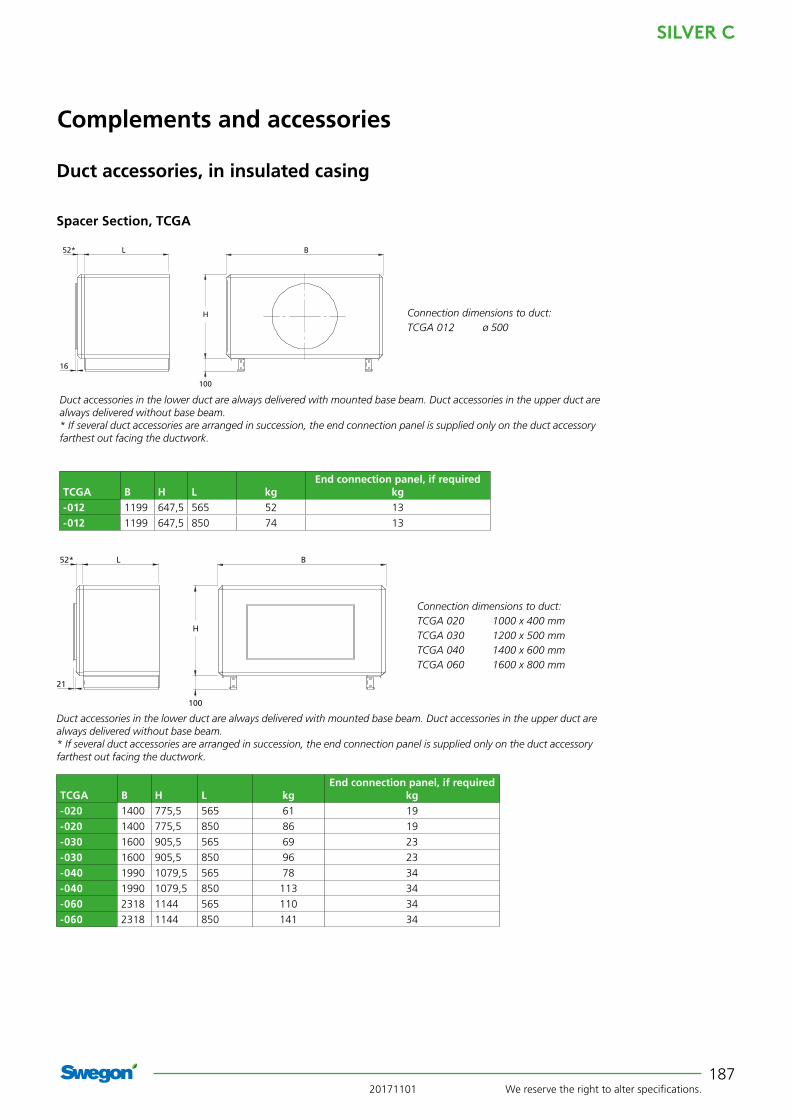
Spacer Section, TCGA
TCIA inspection section. Inspection door the entire length of the section.
TCIA inspection section. Split cover panel/inspection door.
BL52*
H
100
16
Connection dimensions to duct:TCGA 005 ø 315TCGA 008 ø 400
TCGA B H L kgEnd connection panel, if required
kg-005 825 460 565 37 7
-005 825 460 850 54 7
-008 995 542,5 565 43 10
-008 995 542,5 850 63 10
Base beam is optional on duct accessories in the lower duct. Duct accessories in the upper duct are always delivered without base beam.* If several duct accessories are arranged in succession, the end connection panel is supplied only on the duct accessory farthest out facing the ductwork.
Spacer Section, TCGA
20171101 We reserve the right to alter specifications.
SILVER C
187
Complements and accessories
Duct accessories, in insulated casing
BL
21
52*
H
100
Connection dimensions to duct:TCGA 020 1000 x 400 mmTCGA 030 1200 x 500 mmTCGA 040 1400 x 600 mmTCGA 060 1600 x 800 mm
Duct accessories in the lower duct are always delivered with mounted base beam. Duct accessories in the upper duct are always delivered without base beam.* If several duct accessories are arranged in succession, the end connection panel is supplied only on the duct accessory farthest out facing the ductwork.
TCGA B H L kgEnd connection panel, if required
kg-020 1400 775,5 565 61 19
-020 1400 775,5 850 86 19
-030 1600 905,5 565 69 23
-030 1600 905,5 850 96 23
-040 1990 1079,5 565 78 34
-040 1990 1079,5 850 113 34
-060 2318 1144 565 110 34
-060 2318 1144 850 141 34
Spacer Section, TCGA
Connection dimensions to duct:TCGA 012 ø 500
TCGA B H L kgEnd connection panel, if required
kg-012 1199 647,5 565 52 13
-012 1199 647,5 850 74 13
Duct accessories in the lower duct are always delivered with mounted base beam. Duct accessories in the upper duct are always delivered without base beam.* If several duct accessories are arranged in succession, the end connection panel is supplied only on the duct accessory farthest out facing the ductwork.
BL
16
52*
H
100

SILVER C
We reserve the right to alter specifications. 20171101188
21
B
H
100
L52*
Complements and accessories
Duct accessories, in insulated casing
Spacer Section, TCGA
Connection dimensions to duct:TCGA 080 1800 x 1000 mm
TCGA B H L kgEnd connection panel, if required
kg-080 2637 1320 565 129 40
-080 2637 1320 850 174 40
Duct accessories in the lower duct are always delivered with mounted base beam. Duct accessories in the upper duct are always delivered without base beam.* If several duct accessories are arranged in succession, the end connection panel is supplied only on the duct accessory farthest out facing the ductwork.
56* L B
21
H
100
Connection dimensions to duct:TCGA 120 2400 x 1200 mm
* If several duct accessories are arranged in succession, the end connection panel is supplied only on the duct accessory farthest out facing the ductwork.
TCGA B H L kgEnd connection panel, if required
kg-120 3340 1620 720 244 59

20171101 We reserve the right to alter specifications.
SILVER C
189
Complements and accessories
Duct accessories, in insulated casing
BL52*
H
100
16
Connection dimensions to duct:TCIA 012 ø 500
TCIA B H L kgEnd connection panel, if required
kg-012 1199 647,5 565 52 13
-012 1199 647,5 850 74 13
Duct accessories in the lower duct are always delivered with mounted base beam. Duct accessories in the upper duct are always delivered without base beam.* If several duct accessories are arranged in succession, the end connection panel is supplied only on the duct accessory farthest out facing the ductwork.
Connection dimensions to duct:TCIA 005 ø 315TCIA 008 ø 400
TCIA B H L kgEnd connection panel, if required
kg-005 825 460 565 37 7
-005 825 460 850 54 7
-008 995 542,5 565 43 10
-008 995 542,5 850 63 10
Base beam is optional on duct accessories in the lower duct. Duct accessories in the upper duct are always delivered without base beam.* If several duct accessories are arranged in succession, the end connection panel is supplied only on the duct accessory farthest out facing the ductwork.
BL
16
52*
H
100
BL
21
52*
H
100
Connection dimensions to duct:TCIA 020 1000 x 400 mmTCIA 030 1200 x 500 mmTCIA 040 1400 x 600 mmTCIA 060 1600 x 800 mm
Duct accessories in the lower duct are always delivered with mounted base beam. Duct accessories in the upper duct are always delivered without base beam.* If several duct accessories are arranged in succession, the end connection panel is supplied only on the duct accessory farthest out facing the ductwork.
TCIA B H L kgEnd connection panel, if required
kg-020 1400 775,5 565 61 19
-020 1400 775,5 850 86 19
-030 1600 905,5 565 69 23
-030 1600 905,5 850 96 23
-040 1990 1079,5 565 81 34
-040 1990 1079,5 850 117 34
-060 2318 1144 565 103 34
-060 2318 1144 850 143 34
The TCIA inspection section, inspection door in the entire length of the section
SILVER C
We reserve the right to alter specifications. 20171101190
21
B
H
100
L52*
Complements and accessories
Duct accessories, in insulated casing
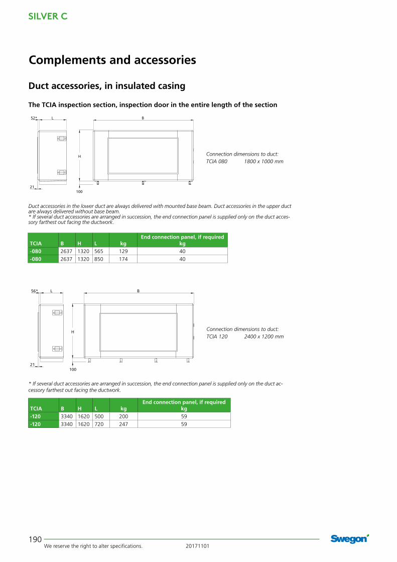
The TCIA inspection section, inspection door in the entire length of the section
Connection dimensions to duct:TCIA 080 1800 x 1000 mm
TCIA B H L kgEnd connection panel, if required
kg-080 2637 1320 565 129 40
-080 2637 1320 850 174 40
Duct accessories in the lower duct are always delivered with mounted base beam. Duct accessories in the upper duct are always delivered without base beam.* If several duct accessories are arranged in succession, the end connection panel is supplied only on the duct acces-sory farthest out facing the ductwork.
56* L B
21
H
100
Connection dimensions to duct:TCIA 120 2400 x 1200 mm
* If several duct accessories are arranged in succession, the end connection panel is supplied only on the duct ac-cessory farthest out facing the ductwork.
TCIA B H L kgEnd connection panel, if required
kg-120 3340 1620 500 200 59
-120 3340 1620 720 247 59

20171101 We reserve the right to alter specifications.
SILVER C
191
Complements and accessories
Duct accessories, in insulated casing
BL52*
H
256
100
16
Connection dimensions to duct:TCIA 012 ø 500
TCIA B H L kgEnd connection panel, if required
kg-012 1199 647,5 565 52 13
-012 1199 647,5 850 74 13
Duct accessories in the lower duct are always delivered with mounted base beam. Duct accessories in the upper duct are always delivered without base beam.* If several duct accessories are arranged in succession, the end connection panel is supplied only on the duct accessory farthest out facing the ductwork.
Connection dimensions to duct:TCIA 005 ø 315TCIA 008 ø 400
TCIA B H L kgEnd connection panel, if required
kg-005 825 460 565 37 7
-005 825 460 850 54 7
-008 995 542,5 565 43 10
-008 995 542,5 850 63 10
Base beam is optional on duct accessories in the lower duct. Duct accessories in the upper duct are always delivered without base beam. * If several duct accessories are arranged in succession, the end connection panel is supplied only on the duct accessory farthest out facing the ductwork.
BL
16
52*
H
100
256
BL
21
52*
H
100
256
Connection dimensions to duct:TCIA 020 1000 x 400 mmTCIA 030 1200 x 500 mmTCIA 040 1400 x 600 mm
Duct accessories in the lower duct are always delivered with mounted base beam. Duct accessories in the upper duct are always delivered without base beam.* If several duct accessories are arranged in succession, the end connection panel is supplied only on the duct accessory farthest out facing the ductwork.
TCIA B H L kgEnd connection panel, if required
kg-020 1400 775,5 565 61 19
-020 1400 775,5 850 86 19
-030 1600 905,5 565 69 23
-030 1600 905,5 850 96 23
-040 1990 1079,5 565 81 34
-040 1990 1079,5 850 117 34
TCIA inspection section, split cover panel/inspection door

SILVER C
We reserve the right to alter specifi cations. 20171101192
Complements and accessories
Unit sound attenuator,TCDAThe TCDA sound attenuators are rectangular sound attenuators designed for mounting directly against the air handling unit.To be installed for horizontal airfl ow.
Technical dataInsulated casing. The outer skin is made of galvanized sheet steel, re-painted in Swegon's own grey metallic paint (closest comparable RAL colour: 9007). The inner skin is made of aluminium-zinc plated sheet steel. Envi-ronmental Class C4.Sound absorption material of type Cleanolon-AL. Cleano-lon-AL consists of mineral wool covered with perforated aluminium foil. Type approved with regard to suitability for cleaning, emissions and fi bre entrainment. The mate-rial conforms to the provisions of Surface Layer Class 1 (the highest class).
InstallationThe sound attenuator should be mounted directly against the air handling unit or insulated duct accessory. Provi-sion for inspection and cleaning must be guaranteed. The cover panel is easy to remove.
Duct accessories, in insulated casing
BL52*
H
100
16
Connection dimensions to duct:TCDA 012 ø 500
TCDA B H L kgEnd connection panel, if required
kg-012 1199 647,5 975 106 13
Duct accessories in the lower duct are always delivered with mounted base beam. Duct accessories in the upper duct are always delivered without base beam.* If several duct accessories are arranged in succession, the end connection panel is supplied only on the duct accessory farthest out facing the ductwork.
Connection dimensions to duct:TCDA 005 ø 315TCDA 008 ø 400
TCDA B H L kgEnd connection panel, if required
kg-005 825 460 975 75 7
-008 995 542,5 975 89 10
Base beam is optional on duct accessories in the lower duct. Duct accessories in the upper duct are always delivered without base beam.* If several duct accessories are arranged in succession, the end connection panel is supplied only on the duct accessory farthest out facing the ductwork.
B
16
52*
H
100
L
20171101 We reserve the right to alter specifications.
SILVER C
193
21
B
H
100
L52*
Complements and accessories
Duct accessories, in insulated casing
BL
21
52*
H
100
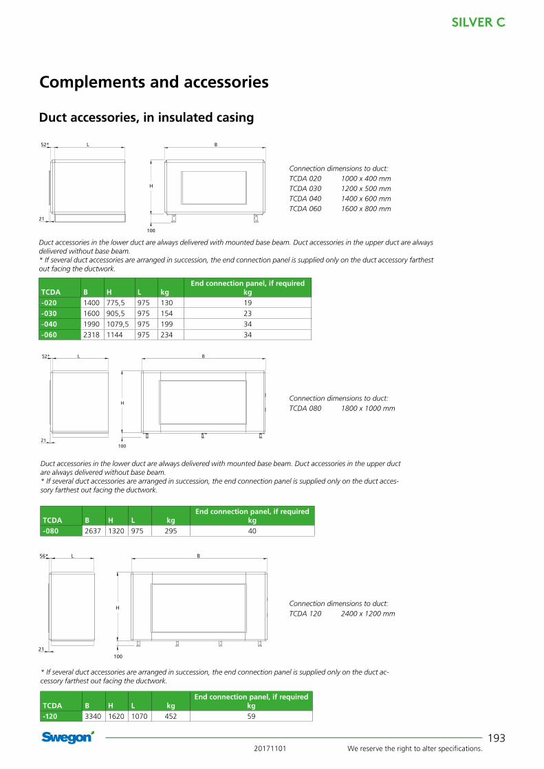
Connection dimensions to duct:TCDA 020 1000 x 400 mmTCDA 030 1200 x 500 mmTCDA 040 1400 x 600 mmTCDA 060 1600 x 800 mm
Duct accessories in the lower duct are always delivered with mounted base beam. Duct accessories in the upper duct are always delivered without base beam.* If several duct accessories are arranged in succession, the end connection panel is supplied only on the duct accessory farthest out facing the ductwork.
TCDA B H L kgEnd connection panel, if required
kg-020 1400 775,5 975 130 19
-030 1600 905,5 975 154 23
-040 1990 1079,5 975 199 34
-060 2318 1144 975 234 34
Connection dimensions to duct:TCDA 080 1800 x 1000 mm
Duct accessories in the lower duct are always delivered with mounted base beam. Duct accessories in the upper duct are always delivered without base beam.* If several duct accessories are arranged in succession, the end connection panel is supplied only on the duct acces-sory farthest out facing the ductwork.
TCDA B H L kgEnd connection panel, if required
kg-080 2637 1320 975 295 40
Connection dimensions to duct:TCDA 120 2400 x 1200 mm
* If several duct accessories are arranged in succession, the end connection panel is supplied only on the duct ac-cessory farthest out facing the ductwork.
TCDA B H L kgEnd connection panel, if required
kg-120 3340 1620 1070 452 59
56* L B
21
H
100
SILVER C
We reserve the right to alter specifi cations. 20171101194
Complements and accessories
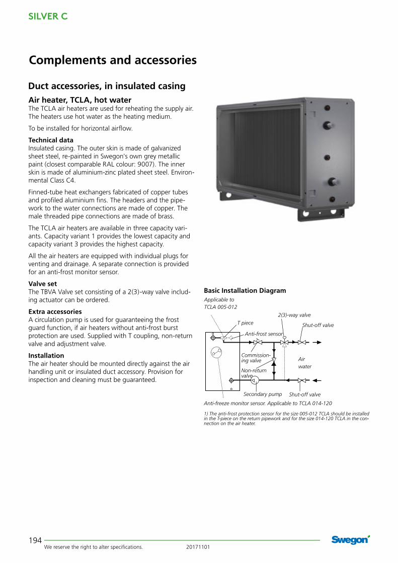
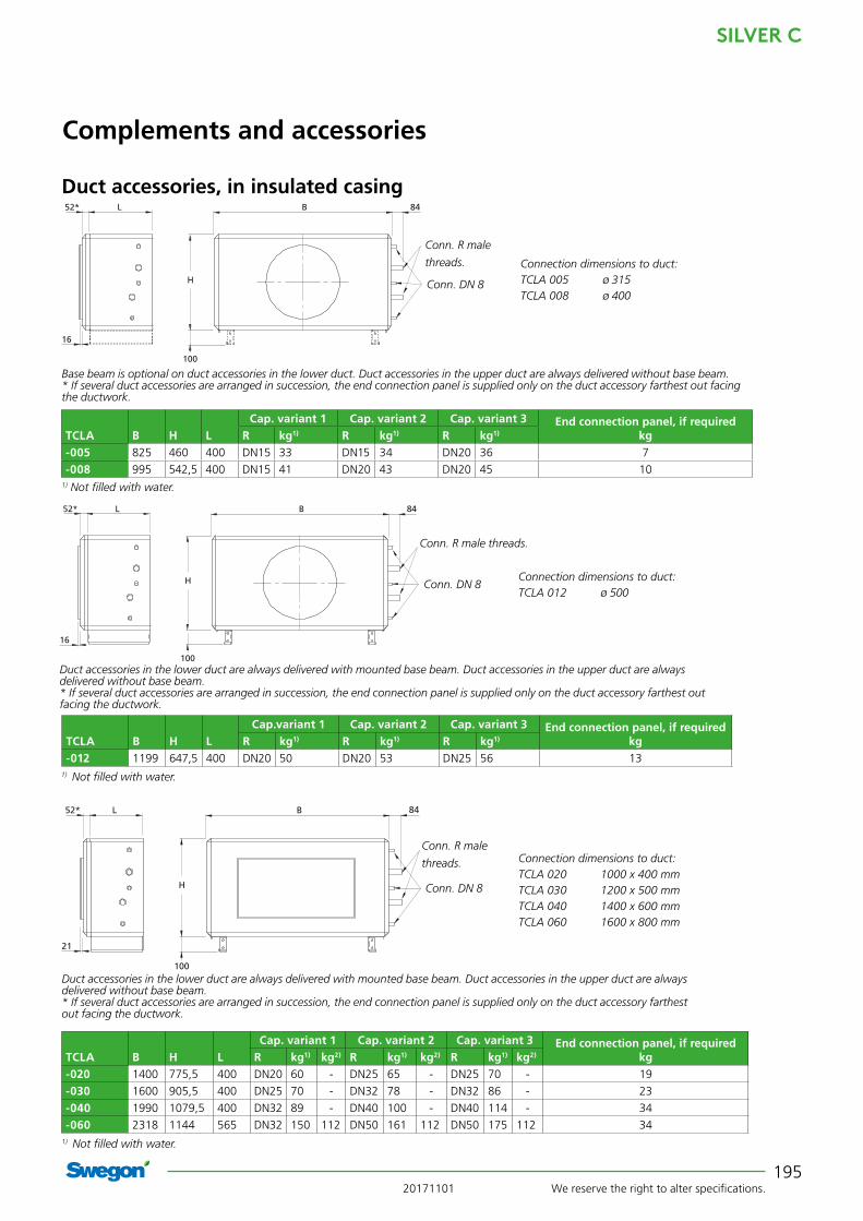
Air heater, TCLA, hot waterThe TCLA air heaters are used for reheating the supply air. The heaters use hot water as the heating medium.
To be installed for horizontal airfl ow.
Technical dataInsulated casing. The outer skin is made of galvanized sheet steel, re-painted in Swegon's own grey metallic paint (closest comparable RAL colour: 9007). The inner skin is made of aluminium-zinc plated sheet steel. Environ-mental Class C4.
Finned-tube heat exchangers fabricated of copper tubes and profi led aluminium fi ns. The headers and the pipe-work to the water connections are made of copper. The male threaded pipe connections are made of brass.
The TCLA air heaters are available in three capacity vari-ants. Capacity variant 1 provides the lowest capacity and capacity variant 3 provides the highest capacity.
All the air heaters are equipped with individual plugs for venting and drainage. A separate connection is provided for an anti-frost monitor sensor.
Valve set The TBVA Valve set consisting of a 2(3)-way valve includ-ing actuator can be ordered.
Extra accessoriesA circulation pump is used for guaranteeing the frost guard function, if air heaters without anti-frost burst protection are used. Supplied with T coupling, non-return valve and adjustment valve.
InstallationThe air heater should be mounted directly against the air handling unit or insulated duct accessory. Provision for inspection and cleaning must be guaranteed.
Basic Installation Diagram
T piece
Anti-frost sensor
Shut-off valve
Airwater
Shut-off valve
2(3)-way valve
Commission-ing valve
Non-return valve
Applicable to TCLA 005-012
Anti-freeze monitor sensor. Applicable to TCLA 014-120
Secondary pump
1) The anti-frost protection sensor for the size 005-012 TCLA should be installed in the T-piece on the return pipework and for the size 014-120 TCLA in the con-nection on the air heater.
Duct accessories, in insulated casing
20171101 We reserve the right to alter specifications.
SILVER C
195
B 84L52*
H
100
16
B 84L
16
52*
H
100
Complements and accessories
Duct accessories, in insulated casing
Conn. R male threads.
Conn. DN 8Connection dimensions to duct:TCLA 012 ø 500
TCLA B H LCap.variant 1 Cap. variant 2 Cap. variant 3 End connection panel, if required
kgR kg1) R kg1) R kg1)
-012 1199 647,5 400 DN20 50 DN20 53 DN25 56 131) Not filled with water.
Duct accessories in the lower duct are always delivered with mounted base beam. Duct accessories in the upper duct are always delivered without base beam.* If several duct accessories are arranged in succession, the end connection panel is supplied only on the duct accessory farthest out facing the ductwork.
Conn. R male
threads.
Conn. DN 8
Connection dimensions to duct:TCLA 005 ø 315TCLA 008 ø 400
TCLA B H LCap. variant 1 Cap. variant 2 Cap. variant 3 End connection panel, if required
kgR kg1) R kg1) R kg1)
-005 825 460 400 DN15 33 DN15 34 DN20 36 7
-008 995 542,5 400 DN15 41 DN20 43 DN20 45 101) Not filled with water.
Base beam is optional on duct accessories in the lower duct. Duct accessories in the upper duct are always delivered without base beam. * If several duct accessories are arranged in succession, the end connection panel is supplied only on the duct accessory farthest out facing the ductwork.
BL
21
52*
H
100
84
Connection dimensions to duct:TCLA 020 1000 x 400 mmTCLA 030 1200 x 500 mmTCLA 040 1400 x 600 mmTCLA 060 1600 x 800 mm
1) Not filled with water.
Duct accessories in the lower duct are always delivered with mounted base beam. Duct accessories in the upper duct are always delivered without base beam.* If several duct accessories are arranged in succession, the end connection panel is supplied only on the duct accessory farthest out facing the ductwork.
Conn. R male
threads.
Conn. DN 8
TCLA B H LCap. variant 1 Cap. variant 2 Cap. variant 3 End connection panel, if required
kgR kg1) kg2) R kg1) kg2) R kg1) kg2)
-020 1400 775,5 400 DN20 60 - DN25 65 - DN25 70 - 19
-030 1600 905,5 400 DN25 70 - DN32 78 - DN32 86 - 23
-040 1990 1079,5 400 DN32 89 - DN40 100 - DN40 114 - 34
-060 2318 1144 565 DN32 150 112 DN50 161 112 DN50 175 112 34

SILVER C
We reserve the right to alter specifications. 20171101196
21
B 95
H
100
L52*
Complements and accessories
Duct accessories, in insulated casing
TCLA B H LCap. variant 1 Cap. variant 2 Cap. variant 3 End connection panel, if required
kgR kg1) kg2) R kg1) kg2) R kg1) kg2)
-080 2637 1320 565 DN50 181 132 DN65 197 132 DN65 217 132 40
Conn. R male
threads.
Conn. DN 8Connection dimensions to duct:TCLA 080 1800 x 1000 mm
1) Including casing, not filled with water.2) Casing only.
Duct accessories in the lower duct are always delivered with mounted base beam. Duct accessories in the upper duct are always delivered without base beam.* If several duct accessories are arranged in succession, the end connection panel is supplied only on the duct acces-sory farthest out facing the ductwork.
9556* L B
21
H
100
TCLA B H LCapacity variant 1 Capacity variant 2 Capacity variant 3 End connection panel, if required
kgR kg1) kg2) R kg1) kg2) R kg1) kg2)
-120 3340 1620 720 DN50 339 256 DN65 384 256 DN65 429 256 59
Conn. R male
threads.
Conn. DN 8Connection dimensions to duct:TCLA 120 2400 x 1200 mm
1) Including casing, not filled with water.2) Casing only.
* If several duct accessories are arranged in succession, the end connection panel is supplied only on the duct ac-cessory farthest out facing the ductwork.

20171101 We reserve the right to alter specifications.
SILVER C
197
Complements and Accessories
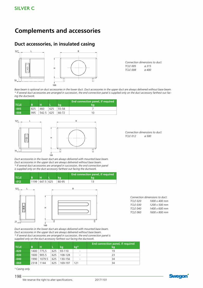
TCLE-02 Electric air heaterAir heater TCLE is used for reheating of the supply air or for certain preheating needs of outdoor air.
To be installed for horizontal airflow.
The integrated thyristor is controlled via signals 0 - 10V. The air heater is equipped with four, five or six series-coupled overheating protections.
Technical dataInsulated casing. The outer skin is made of galvanized sheet steel, re-painted in Swegon's own grey metallic paint (closest comparable RAL colour: 9007). The inner skin is made of aluminium-zinc plated sheet steel. Environ-mental class C4.
The TCLE air heater is available in several capacity variants.
The electrical equipment conforms to the provisions of Degree of Protection IP44.
The air heater is approved for operating temperatures, in the surroundings and the air stream, from -25°C to +40°C.
InstallationThe air heater should be mounted directly against the air handling unit or insulated duct accessory. The space necessary for obtaining a uniform air stream is provided inside the TCLE. Therefore other duct accessories can be fitted downstream of the TCLE without risk of overheat-ing.
Electrical connection. Power must be supplied directly from the electrical distribution box.
Duct accessories, in insulated casing
SILVER C
We reserve the right to alter specifications. 20171101198
BL
21
52*
H
100
BL
16
52*
H
100
B52*
H
L
100
16
Complements and accessories
Duct accessories, in insulated casing
Connection dimensions to duct:TCLE 012 ø 500
TCLE B H L kgEnd connection panel, if required
kg-012 1199 647.5 625 80-95 13
Duct accessories in the lower duct are always delivered with mounted base beam. Duct accessories in the upper duct are always delivered without base beam.* If several duct accessories are arranged in succession, the end connection panel is supplied only on the duct accessory farthest out facing the ductwork.
Connection dimensions to duct:TCLE 005 ø 315TCLE 008 ø 400
TCLE B H L kgEnd connection panel, if required
kg-005 825 460 625 55-58 7
-008 995 542.5 625 66-72 10
Base beam is optional on duct accessories in the lower duct. Duct accessories in the upper duct are always delivered without base beam.* If several duct accessories are arranged in succession, the end connection panel is supplied only on the duct accessory farthest out fac-ing the ductwork.
Connection dimensions to duct:TCLE 020 1000 x 400 mmTCLE 030 1200 x 500 mmTCLE 040 1400 x 600 mmTCLE 060 1600 x 800 mm
TCLE B H L kg kg1)
End connection panel, if requiredkg
-020 1400 775,5 625 93-110 - 19
-030 1600 905.5 625 108-128 - 23
-040 1990 1079.5 625 130-156 - 34
-060 2318 1144 625 169-197 121 34
Duct accessories in the lower duct are always delivered with mounted base beam. Duct accessories in the upper duct are always delivered without base beam.* If several duct accessories are arranged in succession, the end connection panel is supplied only on the duct accessory farthest out facing the ductwork.
1) Casing only.

20171101 We reserve the right to alter specifications.
SILVER C
199
56* L B
21
H
100
H
BL52*
21100
Complements and accessories
Duct accessories, in insulated casing
1) Casing only.
TCLE B H L kg kg1)
End connection panel, if requiredkg
-080 2637 1320 625 204-232 156 40
Connection dimensions to duct:TCLE 080 1800 x 1000 mm
Duct accessories in the lower duct are always delivered with mounted base beam. Duct accessories in the upper duct are always delivered without base beam.* If several duct accessories are arranged in succession, the end connection panel is supplied only on the duct accessory farthest out facing the ductwork.
1) Casing only.
TCLE B H L kg kg1)
End connection panel, if requiredkg
-120 3340 1620 720 326-363 267 59
Connection dimensions to duct:TCLE 120 2400 x 1200 mm
* If several duct accessories are arranged in succession, the end connection panel is supplied only on the duct accessory farthest out facing the ductwork.

SILVER C
We reserve the right to alter specifi cations. 20171101200
Complements and accessories
Air cooler, TCKA (water), TCKC (direct expansion)The TCKA/TCKC air coolers are used for cooling the supply air with chilled water or evaporative refrigerant as the cooling medium.
The TBKAS/TBKCS air coolers are available in several capacity variants that cover existing needs for the corre-sponding size of SILVER C unit.
The TCKA air coolers are equipped with connections for insertion sensors and can be used as a multi-purpose coil (cooling and heating).
To be installed for horizontal airfl ow.
Technical dataInsulated casing. The outer skin is made of galvanized sheet steel, re-painted in Swegon's own grey metallic paint (closest comparable RAL colour: 9007). The inner skin is made of aluminium-zinc plated sheet steel. Environ-mental Class C4.
The TCKA/TCKC air coolers are composed of copper tubes and profi led aluminium fi ns. The TCKA have head-ers and water connections made of copper/brass, with male connection threads. The TCKC have headers and distributor tubes made of copper. The connections are designed for brazed joints.
Valve setThe TBVA Valve set consisting of a 2(3)-way valve includ-ing actuator can be ordered.
InstallationThe air cooler should be mounted directly against the air handling unit or insulated duct accessory. Provision for inspection and cleaning must be guaranteed.Connecting the drainage pipework.
Duct accessories, in insulated casing

20171101 We reserve the right to alter specifications.
SILVER C
201
B 82L52*
H
100
16
Conn. R male
threads.
Conn. DN 8
Connection dimensions to duct:TCKA 005 ø 315TCKA 008 ø 400
TCKA B HCap. variant 1 Cap. variant 2 Cap. variant 4 End connection panel, if required
kgL R kg1) L R kg1) L R kg1)
-005 825 460 475 DN20 49 475 DN25 51 625 DN25 66 7
-008 995 542,5 475 DN25 60 475 DN25 64 625 DN32 83 10
1) Excl. cooling agent
Base beam is optional on duct accessories in the lower duct. Duct accessories in the upper duct are always delivered without base beam.* If several duct accessories are arranged in succession, the end connection panel is supplied only on the duct accessory farthest out facing the ductwork.
Drain conn.
ø 28 male
threads
Duct accessories, in insulated casing
Complements and accessories
B 72L52*
H
100
16
TCKC B H LCapacity variant 1 Capacity variant 2 End connection panel, if required
kgdi du kg1) di du kg1)
-005 825 460 475 1/2" 22 49 5/8" 28 51 7
-008 995 542,5 475 5/8" 28 60 5/8" 35 64 10
1) Excl. cooling agent
Base beam is optional on duct accessories in the lower duct. Duct accessories in the upper duct are always delivered without base beam.* If several duct accessories are arranged in succession, the end connection panel is supplied only on the duct accessory farthest out facing the ductwork.
Drain conn.
ø 28 male
threads
Outer diameter
du male threads
Outer diameter
di male threads
Connection dimensions to duct:TCKC 005 ø 315TCKC 008 ø 400
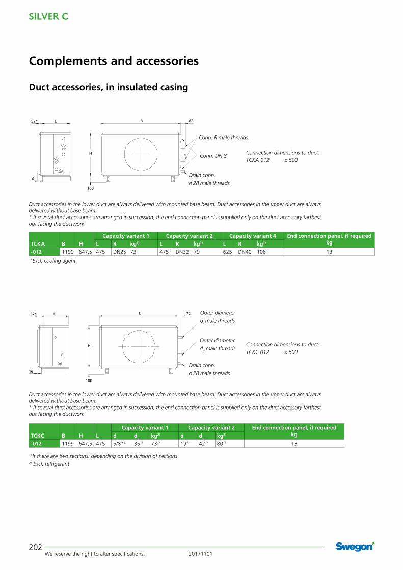
SILVER C
We reserve the right to alter specifications. 20171101202
B 82L
16
52*
H
100
Conn. R male threads.
Conn. DN 8Connection dimensions to duct:TCKA 012 ø 500
TCKA B HCapacity variant 1 Capacity variant 2 Capacity variant 4 End connection panel, if required
kgL R kg1) L R kg1) L R kg1)
-012 1199 647,5 475 DN25 73 475 DN32 79 625 DN40 106 131) Excl. cooling agent
Duct accessories in the lower duct are always delivered with mounted base beam. Duct accessories in the upper duct are always delivered without base beam.* If several duct accessories are arranged in succession, the end connection panel is supplied only on the duct accessory farthest out facing the ductwork.
Drain conn.
ø 28 male threads
Duct accessories, in insulated casing
Complements and accessories
B 72L
16
52*
H
100
Connection dimensions to duct:TCKC 012 ø 500
TCKC B H LCapacity variant 1 Capacity variant 2 End connection panel, if required
kgdi du kg2) di du kg2)
-012 1199 647,5 475 5/8"1) 351) 731) 191) 421) 801) 13
1) If there are two sections: depending on the division of sections
2) Excl. refrigerant
Duct accessories in the lower duct are always delivered with mounted base beam. Duct accessories in the upper duct are always delivered without base beam.* If several duct accessories are arranged in succession, the end connection panel is supplied only on the duct accessory farthest out facing the ductwork.
Drain conn.
ø 28 male threads
Outer diameter
du male threads
Outer diameter
di male threads

20171101 We reserve the right to alter specifications.
SILVER C
203
Duct accessories, in insulated casing
Complements and accessories
BL
21
52*
H
100
82
TCKA B H D
Cap.variant 1 Cap.variant 2 Cap.variant 3 Cap.variant 4 End connec-tion panel, if
required kgL R kg1) kg2) L R kg1) kg2) L R kg1) kg2) L R kg1) kg2)
-020 1400 775,5 28 utv. 475 DN32 91 - 475 DN32 100 - 625 DN40 123 - 625 DN50 132 - 19
-030 1600 905,5 28 utv. 475 DN32 110 - 475 DN40 126 - 625 DN50 156 - 625 DN60 173 - 23
-040 1990 1079,5 28 utv. 475 DN40 138 - 475 DN50 160 - 625 DN65 199 - 625 DN60 223 - 34
-060 2318 1144 DN25 565 DN65 199 108 565 DN65 211 108 565 DN65 225 108 565 DN65 242 108 34
1) Excl. cooling agent 2) Casing only.
Duct accessories in the lower duct are always delivered with mounted base beam. Duct accessories in the upper duct are always delivered without base beam.* If several duct accessories are arranged in succession, the end connection panel is supplied only on the duct accessory farthest out facing the ductwork.
Connection dimensions to duct:TCKA 020 1000 x 400 mmTCKA 030 1200 x 500 mmTCKA 040 1400 x 600 mmTCKA 060 1600 x 800 mm
Conn. R male
threads.
Conn. DN 8
Drain conn. D
TCKA B H DCap.variant 5 Effektvariant 6 End connection panel, if required
kgL R kg1) kg2) L R kg1) kg2)
-060 2318 1144 DN25 565 DN65 210 108 565 DN65 230 108 34
Connection dimensions to duct:TCKC 020 1000 x 400 mmTCKC 030 1200 x 500 mmTCKC 040 1400 x 600 mmTCKC 060 1600 x 800 mm
BL
21
52*
H
100
72
Drain conn. D
Outer diameter
du male threads
Outer diameter
di male threads
TCKC B H L DCap. variant 1 Cap. variant 2 Cap. variant 3 End connection panel, if required
kgdi du kg2) kg3) di du kg2) kg3) kg2) kg3)
-020 1400 775,5 475 28 utv. 221) 421) 941) - 281) 541) 1041) - - - 19
-030 1600 905,5 475 28 utv. 281) 541) 1151) - 281) 541) 1281) - - - 23
-040 1990 1079,5 475 28 utv. 281) 541) 1471) - 281) 541) 1671) - - - 34
-060 2318 1144 565 DN25 - - 210 108 - - 230 108 248 108 34
1) If there are two sections: depending on the division of sections
2) Excl. refrigerant 3) Casing only.
Duct accessories in the lower duct are always delivered with mounted base beam. Duct accessories in the upper duct are always delivered without base beam.* If several duct accessories are arranged in succession, the end connection panel is supplied only on the duct accessory farthest out facing the ductwork.
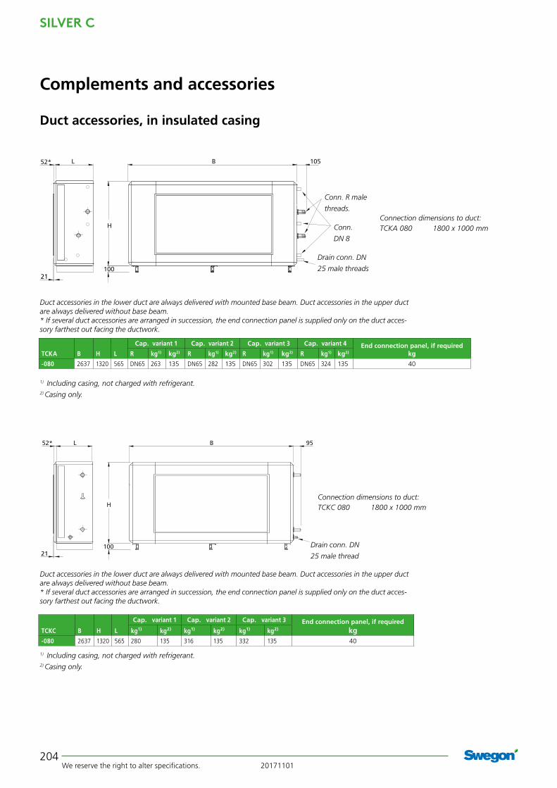
SILVER C
We reserve the right to alter specifications. 20171101204
21
B 95
H
100
L52*
21
B
H
100
L 10552*
Duct accessories, in insulated casing
Complements and accessories
TCKA B H L
Cap. variant 1 Cap. variant 2 Cap. variant 3 Cap. variant 4 End connection panel, if requiredkgR kg1) kg2) R kg1) kg2) R kg1) kg2) R kg1) kg2)
-080 2637 1320 565 DN65 263 135 DN65 282 135 DN65 302 135 DN65 324 135 40
Connection dimensions to duct:TCKA 080 1800 x 1000 mm
Connection dimensions to duct:TCKC 080 1800 x 1000 mm
TCKC B H L
Cap. variant 1 Cap. variant 2 Cap. variant 3 End connection panel, if requiredkgkg1) kg2) kg1) kg2) kg1) kg2)
-080 2637 1320 565 280 135 316 135 332 135 40
1) Including casing, not charged with refrigerant.2) Casing only.
1) Including casing, not charged with refrigerant.2) Casing only.
Conn. R male
threads.
Conn.
DN 8
Drain conn. DN
25 male threads
Drain conn. DN
25 male thread
Duct accessories in the lower duct are always delivered with mounted base beam. Duct accessories in the upper duct are always delivered without base beam.* If several duct accessories are arranged in succession, the end connection panel is supplied only on the duct acces-sory farthest out facing the ductwork.
Duct accessories in the lower duct are always delivered with mounted base beam. Duct accessories in the upper duct are always delivered without base beam.* If several duct accessories are arranged in succession, the end connection panel is supplied only on the duct acces-sory farthest out facing the ductwork.

20171101 We reserve the right to alter specifications.
SILVER C
205
Complements and accessories
Duct accessories, in insulated casing
56* L B
21
H
100
105
TCKA B H L
Capacity variant 1 Capacity variant 2 Capacity variant 3 Capacity variant 4 End connection panel, if requiredkgR kg1) kg2) R kg1) kg2) R kg1) kg2) R3) kg1) kg2)
-120 3340 1620 720 DN65 414 260 DN80 461 260 DN80 513 260 DN100 568 260 59
Connection dimensions to duct:TCKA 120 2400 x 1200 mm
1) Including casing, not charged with refrigerant.2) Casing only.3) The flange is included.
Conn. R male
threads.
Conn. DN 8
Drain conn.
DN 25 male
threads
* If several duct accessories are arranged in succession, the end connection panel is supplied only on the duct acces-sory farthest out facing the ductwork.
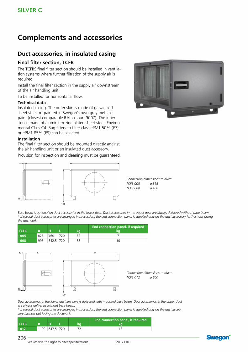
SILVER C
We reserve the right to alter specifi cations. 20171101206
Complements and accessories
Duct accessories, in insulated casingFinal fi lter section, TCFBThe TCFBS fi nal fi lter section should be installed in ventila-tion systems where further fi ltration of the supply air is required.
Install the fi nal fi lter section in the supply air downstream of the air handling unit.
To be installed for horizontal airfl ow.
Technical dataInsulated casing. The outer skin is made of galvanized sheet steel, re-painted in Swegon's own grey metallic paint (closest comparable RAL colour: 9007). The inner skin is made of aluminium-zinc plated sheet steel. Environ-mental Class C4. Bag fi lters to fi lter class ePM1 50% (F7) or ePM1 85% (F9) can be selected.
InstallationThe fi nal fi lter section should be mounted directly against the air handling unit or an insulated duct accessory.
Provision for inspection and cleaning must be guaranteed.
Connection dimensions to duct:TCFB 012 ø 500
TCFB B H L kgEnd connection panel, if required
kg-012 1199 647,5 720 72 13
Duct accessories in the lower duct are always delivered with mounted base beam. Duct accessories in the upper duct are always delivered without base beam.* If several duct accessories are arranged in succession, the end connection panel is supplied only on the duct acces-sory farthest out facing the ductwork.
Connection dimensions to duct:TCFB 005 ø 315TCFB 008 ø 400
TCFB B H L kgEnd connection panel, if required
kg-005 825 460 720 52 7
-008 995 542,5 720 58 10
Base beam is optional on duct accessories in the lower duct. Duct accessories in the upper duct are always delivered without base beam.* If several duct accessories are arranged in succession, the end connection panel is supplied only on the duct accessory farthest out facing the ductwork.
BL52*
H
100
16
BL
16
52*
H
100

20171101 We reserve the right to alter specifications.
SILVER C
207
21
B
H
100
L52*
BL
21
52*
H
100
Complements and accessories
Duct accessories, in insulated casing
Connection dimensions to duct:TCFB 020 1000 x 400 mmTCFB 030 1200 x 500 mmTCFB 040 1400 x 600 mmTCFB 060 1600 x 800 mm
Duct accessories in the lower duct are always delivered with mounted base beam. Duct accessories in the upper duct are always delivered without base beam.* If several duct accessories are arranged in succession, the end connection panel is supplied only on the duct accessory farthest out facing the ductwork.
TCFB B H L kgEnd connection panel, if required
kg-020 1400 775,5 720 88 19
-030 1600 905,5 720 103 23
-040 1990 1079,5 720 119 34
-060 2318 1144 720 150 34
Connection dimensions to duct:TCFB 080 1800 x 1000 mm
Duct accessories in the lower duct are always delivered with mounted base beam. Duct accessories in the upper duct are always delivered without base beam.* If several duct accessories are arranged in succession, the end connection panel is supplied only on the duct acces-sory farthest out facing the ductwork.
TCFB B H L kgEnd connection panel, if required
kg-080 2637 1320 720 198 40
56* L B
21
H
100
Connection dimensions to duct:TCFB 120 2400 x 1200 mm
* If several duct accessories are arranged in succession, the end connection panel is supplied only on the duct acces-sory farthest out facing the ductwork.
TCFB B H L kgEnd connection panel, if required
kg-120 3340 1620 720 297 59

SILVER C
We reserve the right to alter specifications. 20171101208
c
Carbon cartridges
TBFK Carbon filter sectionThe TBFK has activated carbon filter medium designed for improving the air quality indoors by adsorbing gaseous, harmful or foul-smelling substances from the air.
Note that we cannot guarantee one hundred percent elimination of odours due to variations in the impurities and mixtures of various chemical substances arrested in the filter.
The carbon filter cartridges are disposable. They are seat-ed in mounting frames and can be locked in their bayonet socket by simply turning them by hand. The cartridges contain a filter mat made of polyester, which encloses the activated carbon.
The frame construction consists of 38 mm galvanized square profiled sections, painted in RAL 7032. The pro-filed sections are held together by plastic corner pieces.
The outer and inner skins of the cover panels and inspec-tion doors consist of galvanized sheet steel. Intervening 45 mm thick thermal and sound-attenuating insulation.
Cover panels can be removed from the unit.
Inspection doors have hinges and handle.
InstallationThe TBFK carbon filter has a connection frame for slip-clamp jointing designed for installation in the ductwork; see illustration.
Complements and accessories
Note that the TBFK carbon filter is available in
six sizes and that the slip-clamp connection
dimensions follow the connection dimensions
of the SILVER C units.
TBFK Slip clamps,
width x height
B H L kg
without cartridges
Number of
cartridges:
kg
without cartridges
017 850 x 350 1039 546 763 75 17 113
024 1100 x500 1259 656 763 89 24 143
036 1300 x 600 1459 756 763 104 36 185
050 1600 x 700 1759 906 763 120 50 233
072 1800 x 800 1946 1026 763 144 72 307
098 2100 x 1000 2306 1206 763 172 98 393
B
H
L
Duct accessories, in insulated casing

20171101 We reserve the right to alter specifications.
SILVER C
209
C
G
A
BD D
E
H
TBHA Outdoor Air Hood Designed for the intake of outdoor air. The design of the hood makes it difficult for snow and rain drops to enter the hood with the incoming air. The hood is hinged and has air intake louvres on both sides. For SILVER C, sizes 004-040.
TBHB Exhaust Air Hood Designed for the discharge of exhaust air. The hood can be opened on hinges and is equipped with air deflectors that effectively direct the exhaust air upward and give the air high discharge velocity. To achieve low pressure drop, the air deflectors are rounded off on both their long sides. The hoods are equipped with effective provision for drainage. For SILVER C, sizes 004-040.
TBHC Dual-purpose HoodThe TBHC is a combination of TBHA outdoor air hood and TBHB exhaust air hood and is available for the size 004-012 SILVER C units only.
Complements and accessories
Roof hoods and exterior wall hoods
TBHA Outdoor Air Hood
TBHB Exhaust Air Hood
TBHC Dual-purpose Hood
Common for all roof hoodsThe hoods are made of aluminium-zinc plated sheet steel covered with a Plastisol (black) surface coating that conforms to Environmental Class C4.
The roof ducts are made of galvanized sheet steel. Lined inside with 50 mm thick insulation to Fire-resist-ance Class EI30, with a surface covering of type-ap-proved synthetic woven fabric. Two angle brackets for connection to the relevant roof slope are included.
The hoods for the size 004-012 SILVER C units have cir-cular duct connection fitted with type-approved rubber ring seal for jointing to spiral ductwork.
The hoods for the size 014-040 SILVER C units have rectangular duct connection for slip-clamp joint con-nection.
H
E
C
DB
A
B
2 angle brackets (unmounted) are supplied with the hood.
TBHA Outdoor air hood and TBHB Exhaust air hood
For SILVER C
A B C D E H kg
004/005 500 400 850 Ø315 620 800 31
007/008 600 500 950 Ø400 620 800 44
011/012 820 700 1300 Ø500 850 1200 129
014/020 820 700 1300 600 850 1200 129
025 - 040 1120 1000 1700 900 1150 1200 148
For SILVER C
A B C D E H G kg
004/005 1000 900 850 Ø315 620 800 400 70
007/008 1200 1100 950 Ø400 620 800 500 100
011/012 1600 1500 1300 Ø500 850 1200 700 290
TBHC Dual-purpose Hood
2 angle brackets (unmounted) are supplied with the hood.

SILVER C
We reserve the right to alter specifications. 20171101210
L
c/c
D
H
D
B
TBHE Exterior wall hoodDesigned for the admission of outdoor air and the dis-charge of exhaust air. The exhaust air is horizontally discharged through a circular wire mesh grille at the front of the hood. Outdoor air is admitted through a wire mesh grille at the bottom of the hood.
This design effectively prevents short-circuit flow between the outdoor air/exhaust air. For SILVER C, sizes 004-012.
The TBHE exterior wall hoods are made of aluminium-zinc plated sheet steel covered with a Plastisol (light grey) sur-face coating that conforms to Environmental Class C4.
Complements and accessories
Roof hoods and exterior wall hoods
TBHE Exterior wall hood
< Can be reversed. >Outdoor airExhaust air
For SILVER C B c/c D H L kg004/005 200 420 Ø315 520 950 11
0007/008 250 500 Ø400 580 1150 15
011/012 300 600 Ø500 750 1350 20
TCWP Component boxThe TCWP component box is intended for the incorporation of components which must be protected from weather or me-chanical damage. Typical components are valves, actuators, etc.
The component box is enclosed on all sides and has an inspec-tion door that can be selected as a right-hung or left-hung door.
A roof is available as an accessory for outdoor installation.
The cutting of openings for e.g. pipes and electric cables, if required, must be done at the building site.
The base beams are optional extras for the size 005 (Standard on the other sizes).
B954
H
100 J45 45
Size B H J kg005 825 460 579 69
012 1199 648 953 102
030 1600 906 1354 143
040 1990 1080 1726 160

20171101 We reserve the right to alter specifications.
SILVER C
211
GeneralThe TCKC air handling units, including optional unit sections and the COOL DX/DXS chiller can be installed outdoors. This presupposes that the roof, air intake section and exhaust air hood accessories are used. SILVER C air handling units cannot be installed outdoors in applications that call for the fan outlet/inlet to be positioned on the top of the unit.
TBTB RoofThe roof is supplied in kit form, complete with the neces-sary assembly parts and sealing strips. The cover plates for all the door handles are included as standard.
Visible parts are made of galvanized sheet steel, painted in Swegon's grey metallic paint (nearest comparable RAL colour: 9007).
Dimensions
TBTF Intake air section with pre-filter (sizes 004-040)The TBTF intake air section is made of galvanized sheet steel with visible parts i painted in Swegon's grey metallic paint (near-est comparable RAL colour: 9007). The intake air section has a fixed grille and has a hole for drainage. The intake air section has rectangular connection dimensions and the air handling unit is supplied with full face end connection panel. The intake air section is equipped with slip-clamp connection (slip clamps are included). It is possible to order a filter and damper installed in the air intake section. The filter is a compact filter type that conforms to filter class G2, and also works as a water separator. Damper actuators can be ordered with spring return or with modulating function.
TBTA Intake air section (sizes 050-120)The TBTA exhaust air hood is made of aluminium-zinc plated sheet steel.
The exhaust air hood is equipped with a protective screen. For air handling units with standard end connec-tion frame, the exhaust air hoods are circular for unit sizes 004–012 and rectangular with slip-clamp connection for the other unit sizes (slip clamps are included). For air han-dling units with full face connection frames, the exhaust air hoods are always rectangular with slip-clamp connec-tion (slip clamps are included). The exhaust air hood of the size 050-120 SILVER C units is supplied in loose parts, the other components are assembled.
TBTA Exhaust air hoodThe TBTA exhaust air hood is made of aluminium-zinc plated sheet steel. The exhaust air hood is equipped with protective netting. The hood is circular for sizes 004-012 and rectangular with slip-clamp connection for the other sizes (the slip clamps are included).
Duct accessoriesThe duct accessories should be insulated and weather-proofed to the extent necessary. The enclosure classes and permissible ambient temperatures of any actua-tors included must be taken into consideration. See the instructions for the corresponding accessory. If necessary, ensure that the required protection is arranged. Water-tight protective bags for valve actuators are available as accessories. The protective bag has a zip fastener and is made of polyester with internal plastic coating.
Installation tipsSILVER C units should if possible be installed where the most favourable conditions exist from a weather point of view.
The ductwork for supply air and extract air must be insu-lated in accordance with applicable local standards.
Swegon recommends moving the exhaust air hood a distance from the air handling unit by fitting a straight length of duct between them, especially if the exhaust air leaves the air handling unit from its lower level. This will prevent the risk of exhaust air leaking to the outdoor air and the risk of water entering the ventilation system.
Complements and accessories
Outdoor installation
The SILVER C units can be installed outdoors if they are fitted with the roof, air intake section and exhaust air hood accessories. The SILVER C air handling units with the fan outlet/inlet positioned on the top of the unit cannot be fitted with a roof.
Exhaust air
Outdoor air
Extract air
Supply air
27
50-200 50-200 5555 108

SILVER C
We reserve the right to alter specifications. 20171101212
710 (04/05)745 (07/08)
A
B
Mechanical Equipment
Complements and accessories
SILVER C, sizes 004/005 and 007/008Support standSILVER C RX, rotary heat exchanger SILVER C SD, supply air and extract air handling unitsSpecially designed stand. The height of the stand makes it possible to install ducts under the air handling unit.
The stand is made of galvanized sheet steel profiled sec-tions. The stand is supplied in assembly kit form. The long sides (A in the illustration) are used for horizontal installa-tion and the shorter sides (B) are used for vertical installa-tion.
Set of support legsSILVER C PX, counterflow heat exchangerSpecially designed set of legs, the height (745 mm, all sizes) of which makes it possible to arrange ducts under the air handling unit.
The set of legs consists of four legs made of galvanized sheet steel profiled sections. The legs are secured by means of bolts in the base beams under the air handling unit.
Cover holderThe cover holder facilitates the servicing and maintenance of vertically installed units. It consists of a mechanic stay with latch and is supplied in unmounted condition.
Stand for the SILVER C RX/SD, sizes 004/005 and 007/008.
SILVER C CX/SD, sizes 014/020, 025/030, 035/040, 050/060, 070/080, 100/120Droplet eliminatorTo prevent the condensate from being entrained by the air flow at velocities exceeding 3 m/s, coil heat exchang-ers can be equipped with droplet separator on the extract air side.
The material in the droplet eliminator is GLASdek, which is fire resistant and highly absorbent. The pressure drop across the droplet collector is low. On delivery, the droplet eliminator is mounted.
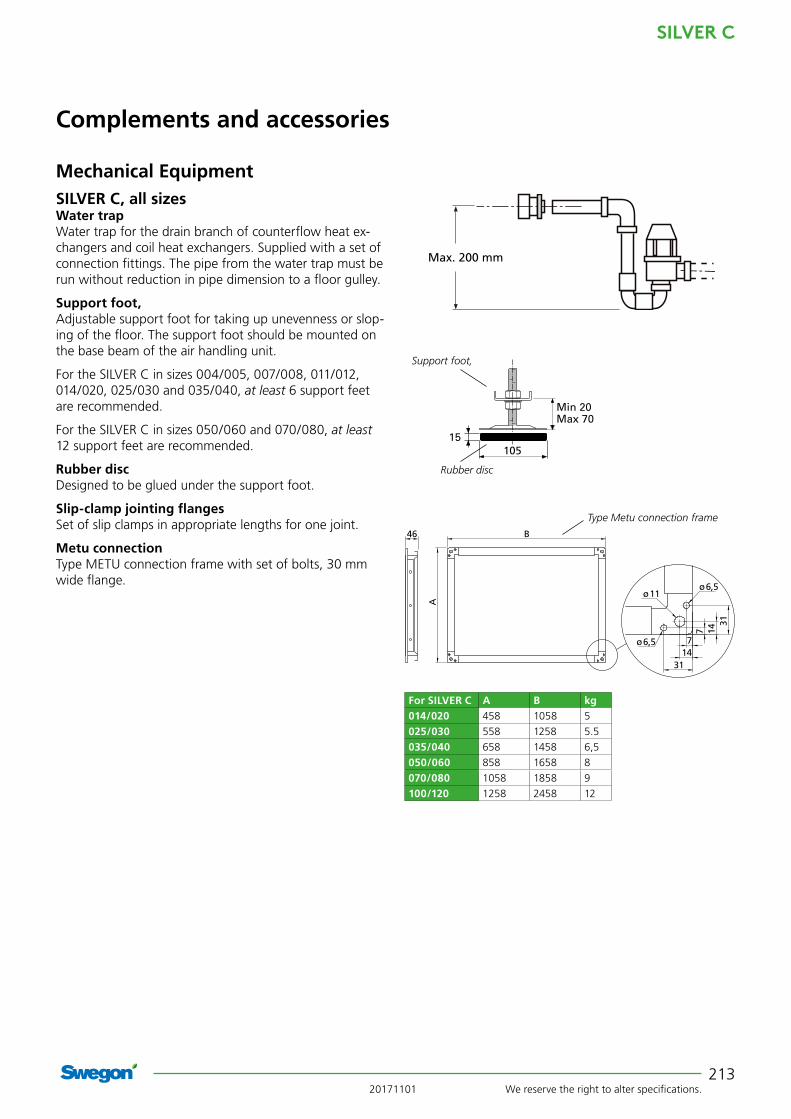
20171101 We reserve the right to alter specifications.
SILVER C
213
Max. 200 mm
105
Support foot,
Rubber disc
For SILVER C A B kg014/020 458 1058 5
025/030 558 1258 5.5
035/040 658 1458 6,5
050/060 858 1658 8
070/080 1058 1858 9
100/120 1258 2458 12
Type Metu connection frame
Mechanical Equipment
Complements and accessories
SILVER C, all sizes Water trapWater trap for the drain branch of counterflow heat ex-changers and coil heat exchangers. Supplied with a set of connection fittings. The pipe from the water trap must be run without reduction in pipe dimension to a floor gulley.
Support foot,Adjustable support foot for taking up unevenness or slop-ing of the floor. The support foot should be mounted on the base beam of the air handling unit.
For the SILVER C in sizes 004/005, 007/008, 011/012, 014/020, 025/030 and 035/040, at least 6 support feet are recommended.
For the SILVER C in sizes 050/060 and 070/080, at least 12 support feet are recommended.
Rubber discDesigned to be glued under the support foot.
Slip-clamp jointing flangesSet of slip clamps in appropriate lengths for one joint.
Metu connectionType METU connection frame with set of bolts, 30 mm wide flange.
B46
A
7 1431
714
31
ø6,5
ø11ø6,5
Max. 200 mm

SILVER C
We reserve the right to alter specifications. 20171101214
Complements and accessories
SILVER C, all sizes End connection panel, SILVER C full faceEnd connection panel for transition between SILVER C in full face version and uninsulated duct accessories or duct. Version as standard SILVER C end connection panel, insulated and pre-painted in Swegon's grey metallic paint (nearest comparable RAL colour: 9007).
Duct accessory with duct connection size corresponding to that of the end connection panel's duct connection size can be ordered (does not apply to sizes 100/120). See section on Uninsulated duct accessories.
The end connection panels are supplied mounted on SILVER C units.
Mechanical equipment
E
21
AC
BD
C x D correspond to the connection dimensions of the duct
For SILVER C/ COOL DX
A B C D E kg
004/005 460 825 300 600 52 7
007/008 542,5 995 400 800 52 10
011/012 647,5 1199 400 1000 52 13
014/020 775,5 1400 500 1200 52 19
025/030 905,5 1600 600 1400 52 23
035/040 1079,5 1990 800 1600 52 34
050/060 1144 2318 1000 1800 52 34
070/080 1320 2637 1200 2400 52 40
100/120 1620 3340 1500 3100 56 59
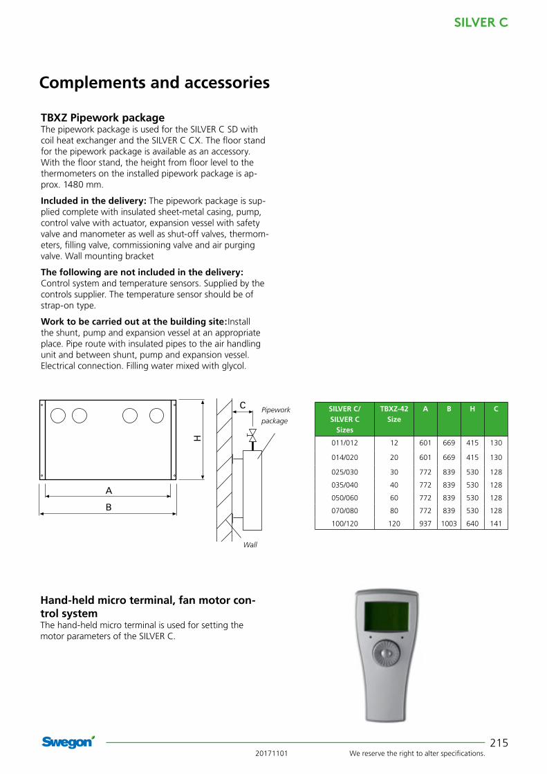
20171101 We reserve the right to alter specifications.
SILVER C
215
Complements and accessories
TBXZ Pipework packageThe pipework package is used for the SILVER C SD with coil heat exchanger and the SILVER C CX. The floor stand for the pipework package is available as an accessory. With the floor stand, the height from floor level to the thermometers on the installed pipework package is ap-prox. 1480 mm.
Included in the delivery: The pipework package is sup-plied complete with insulated sheet-metal casing, pump, control valve with actuator, expansion vessel with safety valve and manometer as well as shut-off valves, thermom-eters, filling valve, commissioning valve and air purging valve. Wall mounting bracket
The following are not included in the delivery: Control system and temperature sensors. Supplied by the controls supplier. The temperature sensor should be of strap-on type.
Work to be carried out at the building site: Install the shunt, pump and expansion vessel at an appropriate place. Pipe route with insulated pipes to the air handling unit and between shunt, pump and expansion vessel. Electrical connection. Filling water mixed with glycol.
Wall
Hand-held micro terminal, fan motor con-trol systemThe hand-held micro terminal is used for setting the motor parameters of the SILVER C.
C Pipework
package
B
A
H
SILVER C/SILVER C
Sizes
TBXZ-42 Size
A B H C
011/012 12 601 669 415 130
014/020 20 601 669 415 130
025/030 30 772 839 530 128
035/040 40 772 839 530 128
050/060 60 772 839 530 128
070/080 80 772 839 530 128
100/120 120 937 1003 640 141
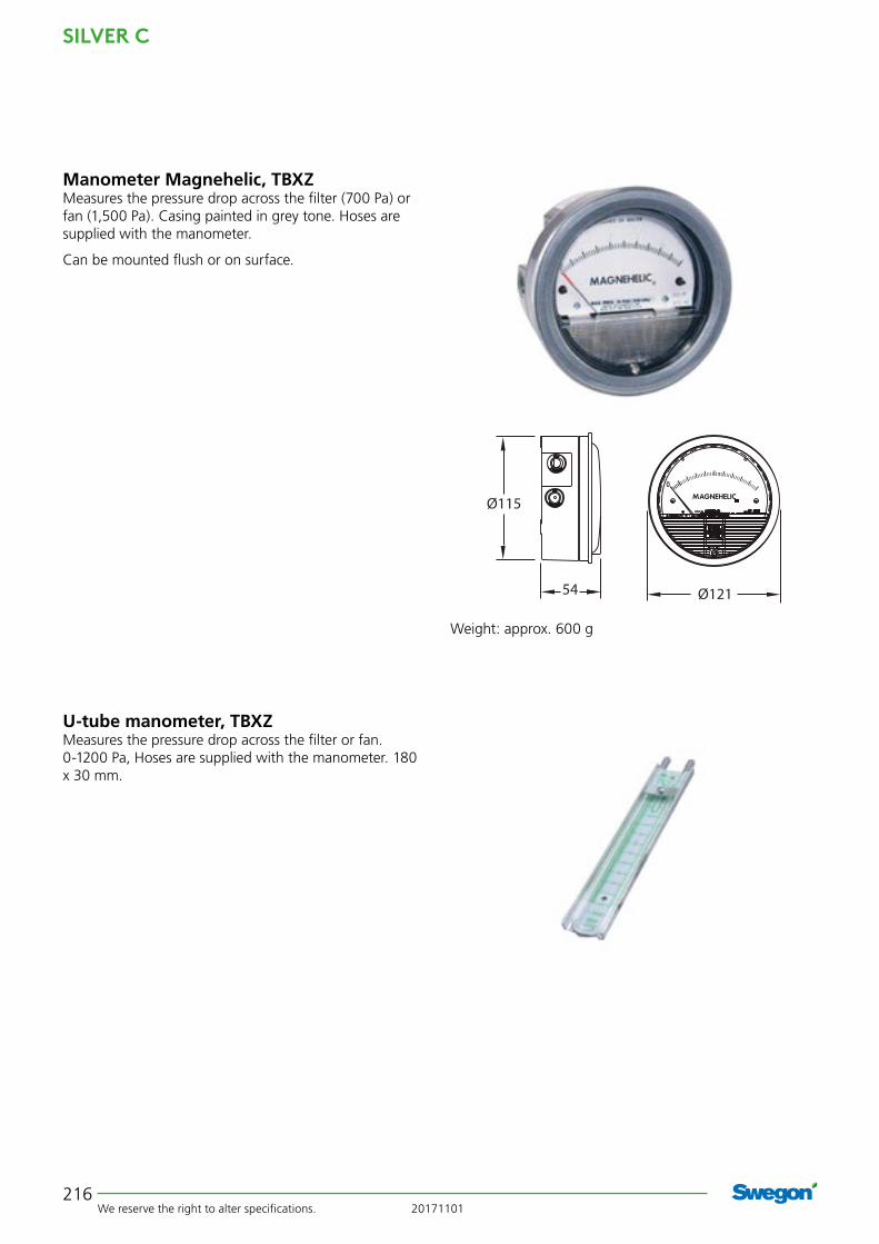
SILVER C
We reserve the right to alter specifications. 20171101216
Manometer Magnehelic, TBXZMeasures the pressure drop across the filter (700 Pa) or fan (1,500 Pa). Casing painted in grey tone. Hoses are supplied with the manometer.
Can be mounted flush or on surface.
U-tube manometer, TBXZMeasures the pressure drop across the filter or fan. 0-1200 Pa, Hoses are supplied with the manometer. 180 x 30 mm.
Weight: approx. 600 g
54 Ø121
Ø115