Description of an atomiser based on a new ultrasonic...
4
Matériaux 2002 – 1/4 Fabrication of metal powders by ultrasonic atomisation Description of an atomiser based on a new ultrasonic device Giulio Caccioppoli 1 — Bernard Clausen 1 — Christian Bonjour 1 — Pascal Pralong 2 1) Haute Ecole Valaisanne Groupe de Compétences Matériaux & Conception Route du Rawyl, 47, CP 2134, CH-1950 Sion 2, Suisse Tél. : 41(0)27 606 8824 / Fax. : 41(0)27 606 8815 / E-mail : [email protected] Tél. : 41(0)27 606 8839 / Fax. : 41(0)27 606 8815 / E-mail : [email protected] Tél. : 41(0)27 606 8800 / Fax. : 41(0)27 606 8815 / E-mail : [email protected] 2) Technologi, développement de logiciels techniques Brignon, CH-1994 Baar (Nendaz), Suisse Tél. : 41(0)79 295 2356 / URL : http://www.technologi.ch / E-mail : [email protected] ABSTRACT. An atomiser is designed for the production of nanostructured, fine-sized metal powders. The alloy is firstly induction-melted under argon atmosphere. The break-up of the superheated melt into spherical droplets is carried out in a tubular ultrasonic resonator under argon or helium atmosphere. Rapid solidification of the atomised melt is the result of convective cooling. Droplet size is governed by the ultrasonic parameters of newly developed transducers, powered by a multifrequency generator. Thanks to such an innovative ultrasonic device, it is possible to control melt break-up further than previous works. Once optimised, this method is expected to be commercially viable for the production of special powders for advanced powder technology processing. KEYWORDS : ultrasonic atomisation, transducer, multifrequency generator, rapid solidification, spherical, fine powders.
Transcript of Description of an atomiser based on a new ultrasonic...
Matériaux 2002 – 1/4
Fabrication of metal powders by ultrasonic atomisation
Description of an atomiser based on a new ultrasonic device
Giulio Caccioppoli 1 — Bernard Clausen 1 — Christian Bonjour 1 — Pascal Pralong 2
1) Haute Ecole Valaisanne Groupe de Compétences Matériaux & Conception Route du Rawyl, 47, CP 2134, CH-1950 Sion 2, Suisse Tél. : 41(0)27 606 8824 / Fax. : 41(0)27 606 8815 / E-mail : [email protected] Tél. : 41(0)27 606 8839 / Fax. : 41(0)27 606 8815 / E-mail : [email protected] Tél. : 41(0)27 606 8800 / Fax. : 41(0)27 606 8815 / E-mail : [email protected]
2) Technologi, développement de logiciels techniques Brignon, CH-1994 Baar (Nendaz), Suisse Tél. : 41(0)79 295 2356 / URL : http://www.technologi.ch / E-mail : [email protected]
ABSTRACT. An atomiser is designed for the production of nanostructured, fine-sized metal powders. The alloy is firstly induction-melted under argon atmosphere. The break-up of the superheated melt into spherical droplets is carried out in a tubular ultrasonic resonator under argon or helium atmosphere. Rapid solidification of the atomised melt is the result of convective cooling. Droplet size is governed by the ultrasonic parameters of newly developed transducers, powered by a multifrequency generator. Thanks to such an innovative ultrasonic device, it is possible to control melt break-up further than previous works. Once optimised, this method is expected to be commercially viable for the production of special powders for advanced powder technology processing.
KEYWORDS : ultrasonic atomisation, transducer, multifrequency generator, rapid solidification, spherical, fine powders.
Matériaux 2002
2
1. Introduction
The latest developments in metal powder processing require specific properties of the powder itself. Indeed, in a process like Metal Injection Moulding (MIM), the control of powder particle size, shape, internal porosity and surface chemistry is an important issue. Appropriate fine powder fabrication methods have therefore to be developed. Most of the world production is carried out by melt atomisation, i.e. the break-up of molten metal into discrete droplets, using essentially the dynamic energy of water or gas jets. Two-fluid atomisation provides high production rates, rapid solidification, and the possibility to control powder properties. It is however not commercially viable for fine powder atomisation because of the huge fluid consumption required to achieve mean particle diameters below 20 µm. The use of ultrasonic vibrations is a possible alternative to high pressure two-fluid atomisation. Although its limits have been reported in the literature, ultrasonic atomisation can now take benefit from newly developed transducers and power sources. Based on this new technology, a prototype atomisation facility has been designed. The way it operates is hereby presented.
2. Ultrasonic atomisation (a brief review)
2.1. The principle of capillary-wave atomisation
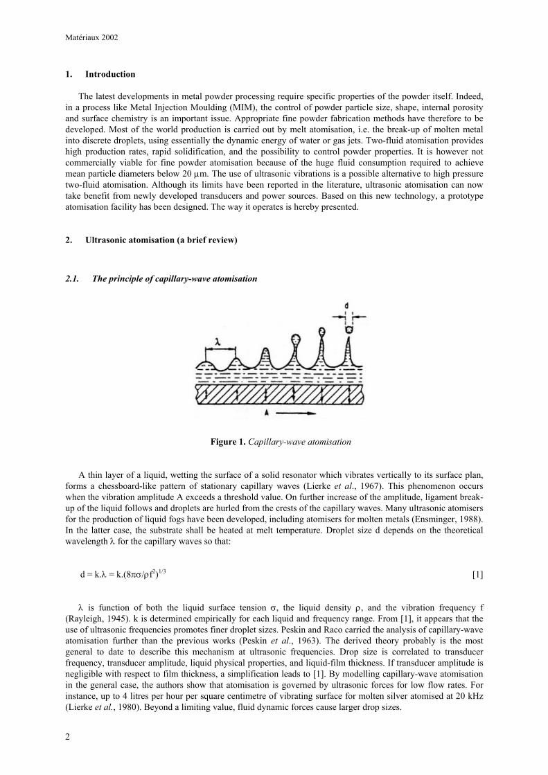
Figure 1. Capillary-wave atomisation
A thin layer of a liquid, wetting the surface of a solid resonator which vibrates vertically to its surface plan, forms a chessboard-like pattern of stationary capillary waves (Lierke et al., 1967). This phenomenon occurs when the vibration amplitude A exceeds a threshold value. On further increase of the amplitude, ligament break-up of the liquid follows and droplets are hurled from the crests of the capillary waves. Many ultrasonic atomisers for the production of liquid fogs have been developed, including atomisers for molten metals (Ensminger, 1988). In the latter case, the substrate shall be heated at melt temperature. Droplet size d depends on the theoretical wavelength λ for the capillary waves so that:
d = k.λ = k.(8πσ/ρf2)1/3 [1]
λ is function of both the liquid surface tension σ, the liquid density ρ, and the vibration frequency f (Rayleigh, 1945). k is determined empirically for each liquid and frequency range. From [1], it appears that the use of ultrasonic frequencies promotes finer droplet sizes. Peskin and Raco carried the analysis of capillary-wave atomisation further than the previous works (Peskin et al., 1963). The derived theory probably is the most general to date to describe this mechanism at ultrasonic frequencies. Drop size is correlated to transducer frequency, transducer amplitude, liquid physical properties, and liquid-film thickness. If transducer amplitude is negligible with respect to film thickness, a simplification leads to [1]. By modelling capillary-wave atomisation in the general case, the authors show that atomisation is governed by ultrasonic forces for low flow rates. For instance, up to 4 litres per hour per square centimetre of vibrating surface for molten silver atomised at 20 kHz (Lierke et al., 1980). Beyond a limiting value, fluid dynamic forces cause larger drop sizes.
Matériaux 2002
3
2.2. Limitations in ultrasonic atomisation
The acoustic activity of a conventional “Langevin” transducer is attenuated by the mechanical load attached to it (see section 3.1). Material selection for both the acoustical wave-guide and the resonator consequently is rather limited, but there are restrictions on dimensions as well (Dunkley et al, 1994). As a result, the resonator has to be located as close to the transducer as possible. Such a configuration is critical in molten metal atomisation, where the resonator shall be heated at melt temperature, which might damage the transducer.
Attenuation decreases the vibration amplitude of the resonator, thus reducing the amount of wave crests where ultrasonic atomisation occurs. In order to maintain a viable atomising efficiency, the flow rate has to be increased which, as shown by Peskin and Raco (see section 2.1), causes large drop sizes.
3. New ultrasonic device
3.1. Newly developed “Hammer” transducers
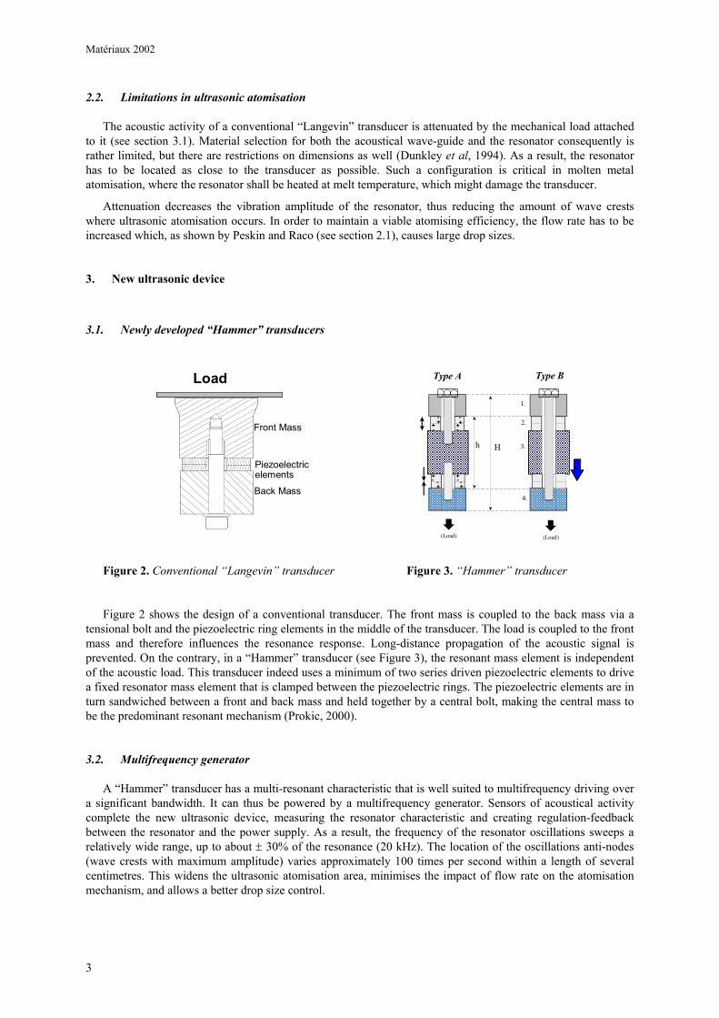
Figure 2. Conventional “Langevin” transducer Figure 3. “Hammer” transducer
Figure 2 shows the design of a conventional transducer. The front mass is coupled to the back mass via a tensional bolt and the piezoelectric ring elements in the middle of the transducer. The load is coupled to the front mass and therefore influences the resonance response. Long-distance propagation of the acoustic signal is prevented. On the contrary, in a “Hammer” transducer (see Figure 3), the resonant mass element is independent of the acoustic load. This transducer indeed uses a minimum of two series driven piezoelectric elements to drive a fixed resonator mass element that is clamped between the piezoelectric rings. The piezoelectric elements are in turn sandwiched between a front and back mass and held together by a central bolt, making the central mass to be the predominant resonant mechanism (Prokic, 2000).
3.2. Multifrequency generator
A “Hammer” transducer has a multi-resonant characteristic that is well suited to multifrequency driving over a significant bandwidth. It can thus be powered by a multifrequency generator. Sensors of acoustical activity complete the new ultrasonic device, measuring the resonator characteristic and creating regulation-feedback between the resonator and the power supply. As a result, the frequency of the resonator oscillations sweeps a relatively wide range, up to about ± 30% of the resonance (20 kHz). The location of the oscillations anti-nodes (wave crests with maximum amplitude) varies approximately 100 times per second within a length of several centimetres. This widens the ultrasonic atomisation area, minimises the impact of flow rate on the atomisation mechanism, and allows a better drop size control.
Load
Front Mass
Back Mass
Piezoelectricelements
H
Type A Type B
1.
2.
3.
4.
h
+
(Load) (Load)
+++-
-
-
-
++
+ +- - - -
Matériaux 2002
4
4. Ultrasonic atomiser
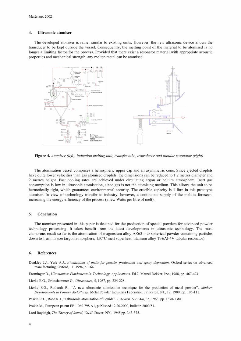
The developed atomiser is rather similar to existing units. However, the new ultrasonic device allows the transducer to be kept outside the vessel. Consequently, the melting point of the material to be atomised is no longer a limiting factor for the process. Provided that there exist a resonator material with appropriate acoustic properties and mechanical strength, any molten metal can be atomised.
Figure 4. Atomiser (left), induction melting unit, transfer tube, transducer and tubular resonator (right)
The atomisation vessel comprises a hemispheric upper cap and an asymmetric cone. Since ejected droplets have quite lower velocities than gas atomised droplets, the dimensions can be reduced to 1.2 metres diameter and 2 metres height. Fast cooling rates are achieved under circulating argon or helium atmosphere. Inert gas consumption is low in ultrasonic atomisation, since gas is not the atomising medium. This allows the unit to be hermetically tight, which guarantees environmental security. The crucible capacity is 1 litre in this prototype atomiser. In view of technology transfer to industry, however, a continuous supply of the melt is foreseen, increasing the energy efficiency of the process (a few Watts per litre of melt).
5. Conclusion
The atomiser presented in this paper is destined for the production of special powders for advanced powder technology processing. It takes benefit from the latest developments in ultrasonic technology. The most clamorous result so far is the atomisation of magnesium alloy AZ63 into spherical powder containing particles down to 1 µm in size (argon atmosphere, 150°C melt superheat, titanium alloy Ti-6Al-4V tubular resonator).
6. References
Dunkley J.J., Yule A.J., Atomization of melts for powder production and spray deposition. Oxford series on advanced manufacturing, Oxford, 11, 1994, p. 164.
Ensminger D., Ultrasonics: Fundamentals, Technology, Applications. Ed.2. Marcel Dekker, Inc., 1988, pp. 467-474.
Lierke E.G., Griesshammer G., Ultrasonics, 5, 1967, pp. 224-228.
Lierke E.G., Ruthardt R., “A new ultrasonic atomization technique for the production of metal powder”. Modern Developments in Powder Metallurgy. Metal Powder Industries Federation, Princeton, NJ., 12, 1980, pp. 105-111.
Peskin R.L., Raco R.J., “Ultrasonic atomization of liquids”. J. Acoust. Soc. Am, 35, 1963, pp. 1378-1381.
Prokic M., European patent EP 1 060 798 A1, published 12.20.2000, bulletin 2000/51.
Lord Rayleigh, The Theory of Sound, Vol.II. Dover, NY., 1945 pp. 343-375.
V1
V2
V7 V8
V3
V4
V5
V6
V10
V9
Recirculation Argon
Echangeur secondaire
Cyclone 1 Cyclone 2
Four
T1
T2 T3p2 p3
V11
Pompe à videà palettes
V15V14
Sonde vide
Sonde débit gaz(en attente)
Dépresseur Root
Argon
V13
V12
Disque de rupture
Sonde pression Keller
E.I.V. SionProjet d'atomisationRS839Date:15.05.2001
VAr
p0
V16
Sonde OxygèneSpectro de masse
sortie
Eau; glycol; Azot liquide
Helium
Oxygène CO2
VHe VO2 VCO2
Débimètre (manuel)
Débimètre(manuel)
V18V17
V19
Ti
Variateur de fréquence
Optionnel Optionnel
Injection Oxygène
Sonotrode
C lausen