
Description - hvaceducationaustralia.comhvaceducationaustralia.com/Resources/PDF/2-6-26F... ·...
38
Description • Methods for determining polarity magnetic flux in relation to current flow in straight conductors and solenoids • circuit operating characteristics • characteristics of the magnetic field produced by a three phase winding • calculated speed of rotation of the rotating magnetic field • basic principle of operation, construction and applications of a three phase induction motor
Transcript of Description - hvaceducationaustralia.comhvaceducationaustralia.com/Resources/PDF/2-6-26F... ·...

Description
• Methods for determining polarity magnetic flux in relation to current flow in straight conductors and solenoids
• circuit operating characteristics
• characteristics of the magnetic field produced by a three phase winding
• calculated speed of rotation of the rotating magnetic field
• basic principle of operation, construction and applications of a three phase induction motor

Description
• three phase induction motor connections
• reversing the direction of rotation of a
three phase induction motor
• equipment and methods for testing the
motor winding resistance and insulation
properties
• effects of incorrect wiring a three phase
motor.

Electromagnets
• It was discovered that when a current
flows in a conductor, it creates a magnetic
field around the conductor.
• The strength of the magnetic field is
proportional to the current.
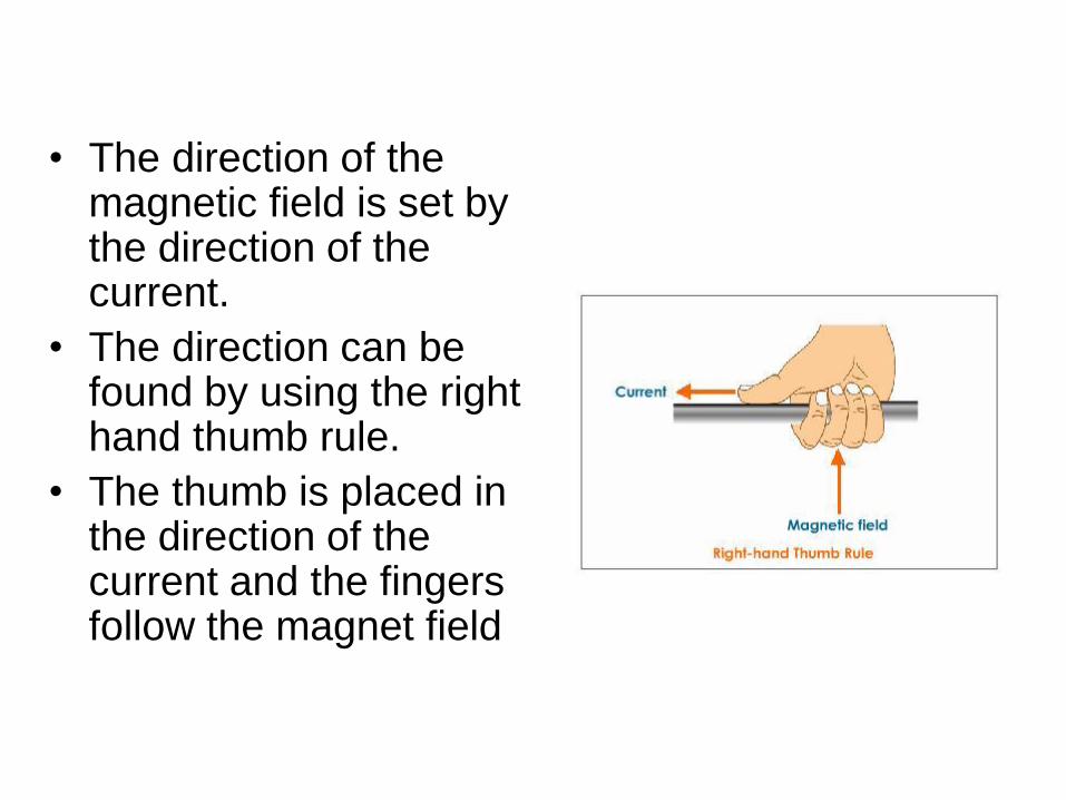
• The direction of the magnetic field is set by the direction of the current.
• The direction can be found by using the right hand thumb rule.
• The thumb is placed in the direction of the current and the fingers follow the magnet field

• This is can also be shown by looking at
the ends of the conductor.
• Cross represents current flowing into the
screen, dot represents current flowing out
of the screen.

Made into a coil
• Many have found on the job,
that by placing a conductor
through the jaws of a clamp
meter several times the
reading is increase by a
multiplying the current by the
number of turns.
• This would read twice the
current.

• When current flows in a coil, the
resultant magnetic fields around
each conductor combine to
create a magnet.
• In this case the magnetic lines
of force are entering the bottom
and leaving the top. This would
make the bottom a south and
the top a north.

Right hand grip rule
• Fingers follow the direction of the current
through the coil, and the thumb points to
the north pole.

Three windings 120° apart

3 phase supply 120° apart


Rate of rotation
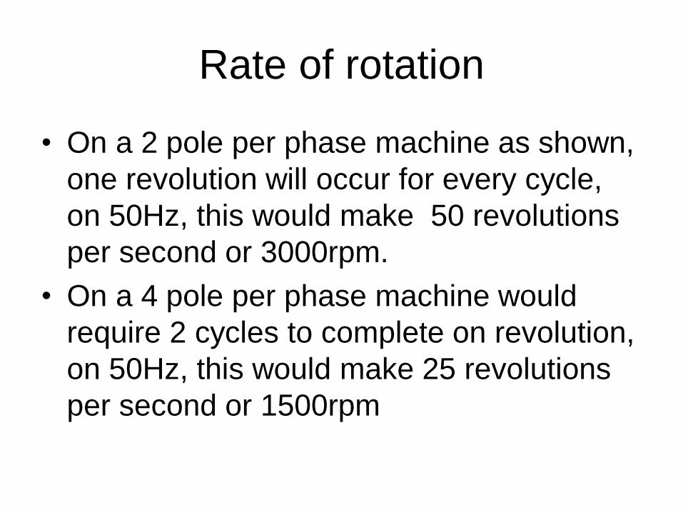
• On a 2 pole per phase machine as shown,
one revolution will occur for every cycle,
on 50Hz, this would make 50 revolutions
per second or 3000rpm.
• On a 4 pole per phase machine would
require 2 cycles to complete on revolution,
on 50Hz, this would make 25 revolutions
per second or 1500rpm

• From this we can use the formula
• n = speed in rpm
• f = frequency in Hertz
• P = number of poles per phase
(120 is derived from 60 seconds in a minute and two poles per magnet)
n =
120f
P

A cage is placed inside the rotating
magnetic field

As there is relative motion between
the rotating magnetic field and the
bars of the rotor a voltage is
induced in the bars
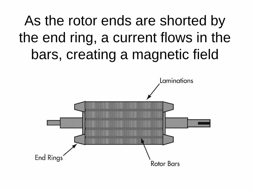
As the rotor ends are shorted by
the end ring, a current flows in the
bars, creating a magnetic field


On start
• At standstill, also known as locked rotor, the
motor acts like a shorted transformer.
• A large current is drawn from the supply
• This can be between 6 – 10 times the normal
operating current.
• The current in the rotor creates a magnetic field
• Some text quote 6 -8 whilst others quote 8 – 10 so to simplify we
say 6 -10. We shall use 6 times in most cases in this course.
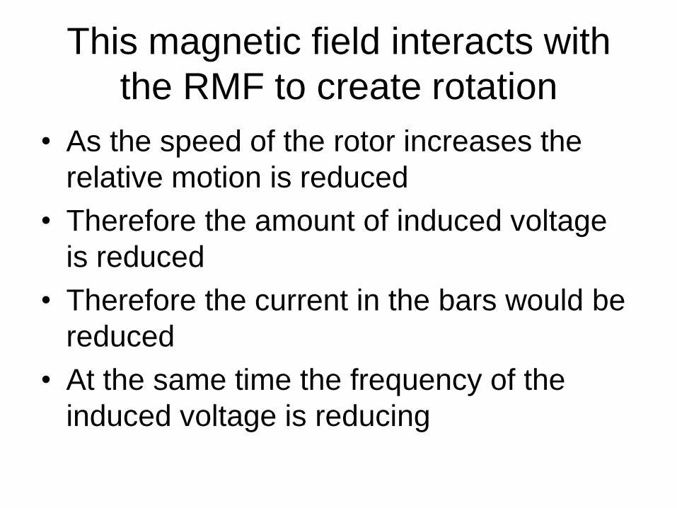
This magnetic field interacts with
the RMF to create rotation
• As the speed of the rotor increases the
relative motion is reduced
• Therefore the amount of induced voltage
is reduced
• Therefore the current in the bars would be
reduced
• At the same time the frequency of the
induced voltage is reducing

• The rotor has resistance and inductance.
• As frequency decreases so does XL
• When XL = R maximum interaction
between the magnetic fields occurs.
• Known as break over or break down
torque

Rotor XL and R determine torque
curve
Rotor
Frequency
Rotor XL
Rotor R
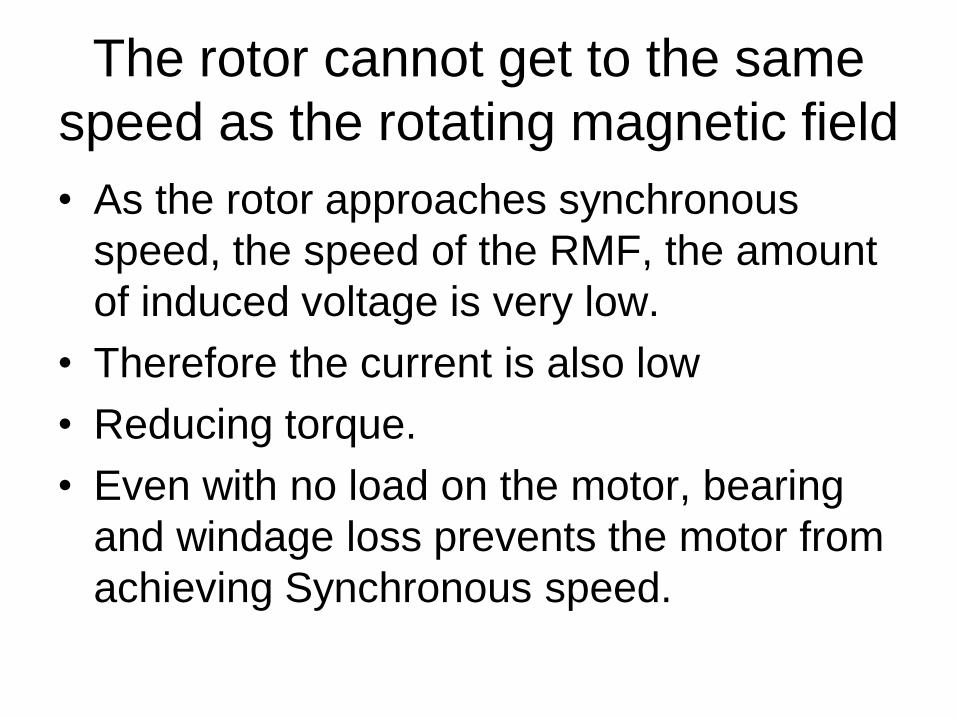
The rotor cannot get to the same
speed as the rotating magnetic field
• As the rotor approaches synchronous
speed, the speed of the RMF, the amount
of induced voltage is very low.
• Therefore the current is also low
• Reducing torque.
• Even with no load on the motor, bearing
and windage loss prevents the motor from
achieving Synchronous speed.

The difference between RMF and
rotor
• This is known as slip
• It is expressed as a
percentage of RMF
%s =
nRMF - nROTOR
nRMF

Different cages give different
curves
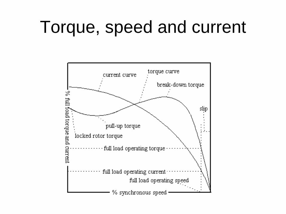
Torque, speed and current

Motor connections
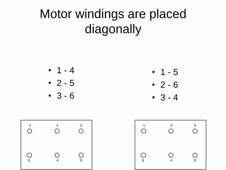
Motor windings are placed
diagonally
• 1 - 4
• 2 - 5
• 3 - 6
• 1 - 5
• 2 - 6
• 3 - 4
1 2 3
56 4
1 2 3
56 4

1 2 3
56 4


Delta connection

Star connection

Testing • Check continuity of windings, 1 – 4, 2 – 5, 3 – 6.
• Each reading should be identical
• Insulation test each winding to earth (500V)
• Insulation test between windings (1000V)
• Not less than 1MΩ
1 2 3
56 4

Synchronous motor
• A synchronous motor is very simular to an
Induction motor
• The stator is identical
• The rotor is the only change
• Instead of a cage a magnet or an
electromagnet is placed on the rotor


Advantage
• By placing a magnet on the rotor the rotor
will rotate at the same speed as the
rotating magnetic field irrespective of load
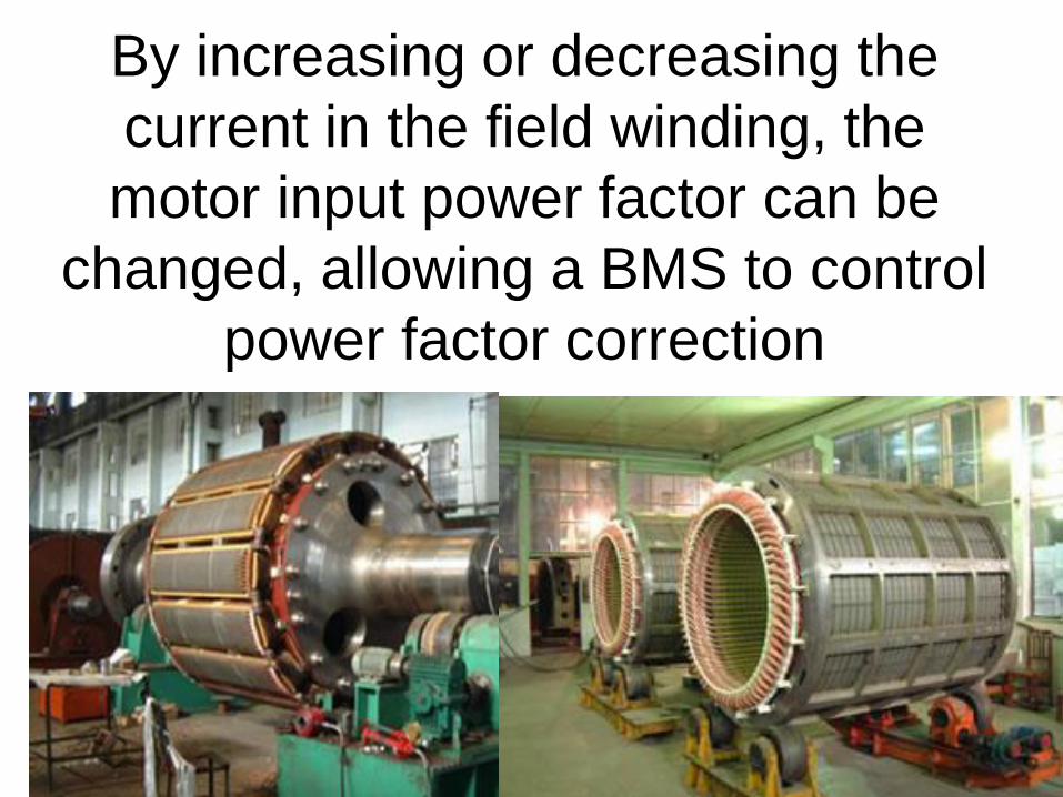
By increasing or decreasing the
current in the field winding, the
motor input power factor can be
changed, allowing a BMS to control
power factor correction