Description Destinations Features
36
SURPASS hiE 9200 V4.3, operating documentation, issue 5 Destination Features Approval Date 2009-06-04
-
Upload
phamdung4518 -
Category
Documents
-
view
46 -
download
1
Transcript of Description Destinations Features
SURPASS hiE 9200 V4.3, operating documentation, issue 5
Destination Features
Approval Date 2009-06-04
2
Destination Features
Id:0900d8058001c384
The information in this document is subject to change without notice and describes only the product defined in the introduction of this documentation. This documentation is intended for the use of Nokia Siemens Networks customers only for the purposes of the agreement under which the document is submitted, and no part of it may be used, reproduced, modified or transmitted in any form or means without the prior written permission of Nokia Siemens Networks. The documentation has been prepared to be used by professional and properly trained personnel, and the customer assumes full responsibility when using it. Nokia Siemens Networks welcomes customer comments as part of the process of continuous development and improvement of the documentation.
The information or statements given in this documentation concerning the suitability, capacity, or performance of the mentioned hardware or software products are given "as is" and all liability arising in connection with such hardware or software products shall be defined conclusively and finally in a separate agreement between Nokia Siemens Networks and the customer. However, Nokia Siemens Networks has made all reasonable efforts to ensure that the instructions contained in the document are adequate and free of material errors and omissions. Nokia Siemens Networks will, if deemed necessary by Nokia Siemens Networks, explain issues which may not be covered by the document.
Nokia Siemens Networks will correct errors in this documentation as soon as possible. IN NO EVENT WILL Nokia Siemens Networks BE LIABLE FOR ERRORS IN THIS DOCUMENTA-TION OR FOR ANY DAMAGES, INCLUDING BUT NOT LIMITED TO SPECIAL, DIRECT, INDI-RECT, INCIDENTAL OR CONSEQUENTIAL OR ANY LOSSES, SUCH AS BUT NOT LIMITED TO LOSS OF PROFIT, REVENUE, BUSINESS INTERRUPTION, BUSINESS OPPORTUNITY OR DATA,THAT MAY ARISE FROM THE USE OF THIS DOCUMENT OR THE INFORMATION IN IT.
This documentation and the product it describes are considered protected by copyrights and other intellectual property rights according to the applicable laws.
The wave logo is a trademark of Nokia Siemens Networks Oy. Nokia is a registered trademark of Nokia Corporation. Siemens is a registered trademark of Siemens AG.
Other product names mentioned in this document may be trademarks of their respective owners, and they are mentioned for identification purposes only.
Copyright © Nokia Siemens Networks 2007. All rights reserved
f Important Notice on Product Safety Elevated voltages are inevitably present at specific points in this electrical equipment. Some of the parts may also have elevated operating temperatures.
Non-observance of these conditions and the safety instructions can result in personal injury or in property damage.
Therefore, only trained and qualified personnel may install and maintain the system.
The system complies with the standard EN 60950 / IEC 60950. All equipment connected has to comply with the applicable safety standards.
The same text in German:
Wichtiger Hinweis zur Produktsicherheit
In elektrischen Anlagen stehen zwangsläufig bestimmte Teile der Geräte unter Span-nung. Einige Teile können auch eine hohe Betriebstemperatur aufweisen.
Eine Nichtbeachtung dieser Situation und der Warnungshinweise kann zu Körperverlet-zungen und Sachschäden führen.
Deshalb wird vorausgesetzt, dass nur geschultes und qualifiziertes Personal die Anlagen installiert und wartet.
Das System entspricht den Anforderungen der EN 60950 / IEC 60950. Angeschlossene Geräte müssen die zutreffenden Sicherheitsbestimmungen erfüllen.
3
Destination Features
Id:0900d8058001c384
Table of ContentsThis document has 36 pages.
1 Destinations . . . . . . . . . . . . . . . . . . . . . . . . . . . . . . . . . . . . . . . . . . . . . . . . . 7
2 Feature: A-Number-Dependent Traffic Routing . . . . . . . . . . . . . . . . . . . . . . 82.1 Mode of operation . . . . . . . . . . . . . . . . . . . . . . . . . . . . . . . . . . . . . . . . . . . . . 82.1.1 A-number screening for subscriber identification . . . . . . . . . . . . . . . . . . . . . 92.1.2 A-number screening for special traffic routing . . . . . . . . . . . . . . . . . . . . . . 102.1.3 A-number screening for special zoning. . . . . . . . . . . . . . . . . . . . . . . . . . . . 102.1.4 Black/White List Screening due to signalled CAC . . . . . . . . . . . . . . . . . . . 112.1.5 Compatibility . . . . . . . . . . . . . . . . . . . . . . . . . . . . . . . . . . . . . . . . . . . . . . . . 112.1.6 Requirements . . . . . . . . . . . . . . . . . . . . . . . . . . . . . . . . . . . . . . . . . . . . . . . 122.2 Administration . . . . . . . . . . . . . . . . . . . . . . . . . . . . . . . . . . . . . . . . . . . . . . . 12
3 Feature: Traffic Distribution among several Carriers (Carrier Quota) . . . . . 133.1 Mode of operation . . . . . . . . . . . . . . . . . . . . . . . . . . . . . . . . . . . . . . . . . . . . 133.1.1 Example of a call setup using the feature Carrier Selection via Quota Groups
153.2 Adminstration . . . . . . . . . . . . . . . . . . . . . . . . . . . . . . . . . . . . . . . . . . . . . . . 16
4 Feature: Call Divergence Destination (CDD) . . . . . . . . . . . . . . . . . . . . . . . 174.1 Mode of operation . . . . . . . . . . . . . . . . . . . . . . . . . . . . . . . . . . . . . . . . . . . . 184.2 Call charge registration . . . . . . . . . . . . . . . . . . . . . . . . . . . . . . . . . . . . . . . . 184.3 Requirements . . . . . . . . . . . . . . . . . . . . . . . . . . . . . . . . . . . . . . . . . . . . . . . 184.4 Administration . . . . . . . . . . . . . . . . . . . . . . . . . . . . . . . . . . . . . . . . . . . . . . . 19
5 Feature: Destination Areas with Transmission-Optimized Routing (TMR/IPI) 20
5.1 Mode of operation . . . . . . . . . . . . . . . . . . . . . . . . . . . . . . . . . . . . . . . . . . . . 205.2 Requirements . . . . . . . . . . . . . . . . . . . . . . . . . . . . . . . . . . . . . . . . . . . . . . . 255.3 Administration . . . . . . . . . . . . . . . . . . . . . . . . . . . . . . . . . . . . . . . . . . . . . . . 25
6 Feature: Hard to Reach Control (HTRC) . . . . . . . . . . . . . . . . . . . . . . . . . . 266.1 Mode of operation . . . . . . . . . . . . . . . . . . . . . . . . . . . . . . . . . . . . . . . . . . . . 276.2 Requirements . . . . . . . . . . . . . . . . . . . . . . . . . . . . . . . . . . . . . . . . . . . . . . . 306.3 Administration Hints and Examples . . . . . . . . . . . . . . . . . . . . . . . . . . . . . . 30
7 Feature: Mass Call Control (MCC) . . . . . . . . . . . . . . . . . . . . . . . . . . . . . . . 317.1 Mode of operation . . . . . . . . . . . . . . . . . . . . . . . . . . . . . . . . . . . . . . . . . . . . 327.2 Requirements . . . . . . . . . . . . . . . . . . . . . . . . . . . . . . . . . . . . . . . . . . . . . . . 357.3 Administration . . . . . . . . . . . . . . . . . . . . . . . . . . . . . . . . . . . . . . . . . . . . . . . 36
4
Destination Features
Id:0900d8058001c384
List of FiguresFigure 1 Line types for screening (calling party number check) . . . . . . . . . . . . . . . 9Figure 2 A-number screening for subscriber identification . . . . . . . . . . . . . . . . . . 10Figure 3 A-number screening for special traffic routing . . . . . . . . . . . . . . . . . . . . 10Figure 4 A-number screening for special zoning. . . . . . . . . . . . . . . . . . . . . . . . . . 11Figure 5 Black/white list screening . . . . . . . . . . . . . . . . . . . . . . . . . . . . . . . . . . . . 11Figure 6 Traffic routing with load sharing . . . . . . . . . . . . . . . . . . . . . . . . . . . . . . . 14Figure 7 Carrier Quota load sharing . . . . . . . . . . . . . . . . . . . . . . . . . . . . . . . . . . . 16Figure 8 Traffic routing via a TMR/IPI selection destination . . . . . . . . . . . . . . . . . 23Figure 9 TMR / IPI selection destinations . . . . . . . . . . . . . . . . . . . . . . . . . . . . . . . 24Figure 10 Example of HTRC operation . . . . . . . . . . . . . . . . . . . . . . . . . . . . . . . . . . 28Figure 11 Operating principle of mass call control . . . . . . . . . . . . . . . . . . . . . . . . . 33Figure 12 Example of detection of the directory number of a mass call destination34

5
Destination Features
Id:0900d8058001c384
List of TablesTable 1 TMR/IPI matrix . . . . . . . . . . . . . . . . . . . . . . . . . . . . . . . . . . . . . . . . . . . 21Table 2 Examples of MCC monitoring . . . . . . . . . . . . . . . . . . . . . . . . . . . . . . . . 35

6
Destination Features
Id:0900d8058001c384
7
Destination Features Destinations
Id:0900d80580017c48
1 DestinationsDestinations represent the logical link between digit translation and accessing a physical path (trunk group) leading out of the network node. Their main function is in overflow control for the routes.
A logical destination area is accessed by analyzing the dialing information via one or more code points. Generally two kinds of Destinations may be differentiated:
• Destinations with Digit RetranslationDestinations with digit retranslation have no routes associated with them. They exist for the sole purpose of transforming the incoming code. For more details ref. to OMN:EXCH-RO/NT.
• Destinations with Standard RoutingBasically this type of destination is used to select a route with idle trunks to the desired destination (ref. to OMN:EXCH-RO/NT). The EWSD offers a variety of “des-tination features” to detect the proper trunks and to set up the connection:
– A-Number-Dependent Traffic Routing
– A-number screening for subscriber identification
– A-number screening for special traffic routing
– Fraud Prevention (command path: BLSTWLST) , depicted in OMN:EXCH-RO/NT)
– Traffic distribution among several carriers (Carrier Quota)
– Call Divergence Destination (CDD)
– Destination Areas with Transmission-Optimized Routing (TMR/IPI)
In high load phases or unforeseen events such as adverse weather conditions, earth-quakes, etc. special “Traffic Control Destinations” are offered to make the most of such extreme network conditions:
– Hard to Reach Control (HTRC)
– Mass Call Control (MCC)
8
Destination Features
Id:0900d80580017dde
Feature: A-Number-Dependent Traffic Routing
2 Feature: A-Number-Dependent Traffic RoutingThe feature A-Number-Dependent Traffic Routing permits the identification of autho-rized and unauthorized subscribers during connection setup. The subscriber’s directory number and, where applicable, the carrier access code are used as identification crite-ria.
The feature also covers an A-number-dependent routing and zoning and allows “Fraud Prevention”.
Operator benefits
• identification of subscribers as contract partners
• A-number-dependent traffic routing (e.g. via routes with a particularly high transmis-sion quality)
• A-number-dependent zoning
2.1 Mode of operationThe feature A-Number-Dependent Traffic Routing can be used in EWSD transit exchanges. It offers the following possibilities:
• A-number screening for subscriber identification
• A-number screening for special traffic routing
• A-number screening for special zoning
• Fraud Prevention
An evaluation is also made on the basis of:
– A-number range
– origin identifier
hiE9200
calling subscriber
A-number evaluation
authorized traffic
un- authorized traffic
STOP
Network node
Network node
Network node
calling subscriber
called subscriber
9
Destination Features Feature: A-Number-Dependent Traffic Routing
Id:0900d80580017dde
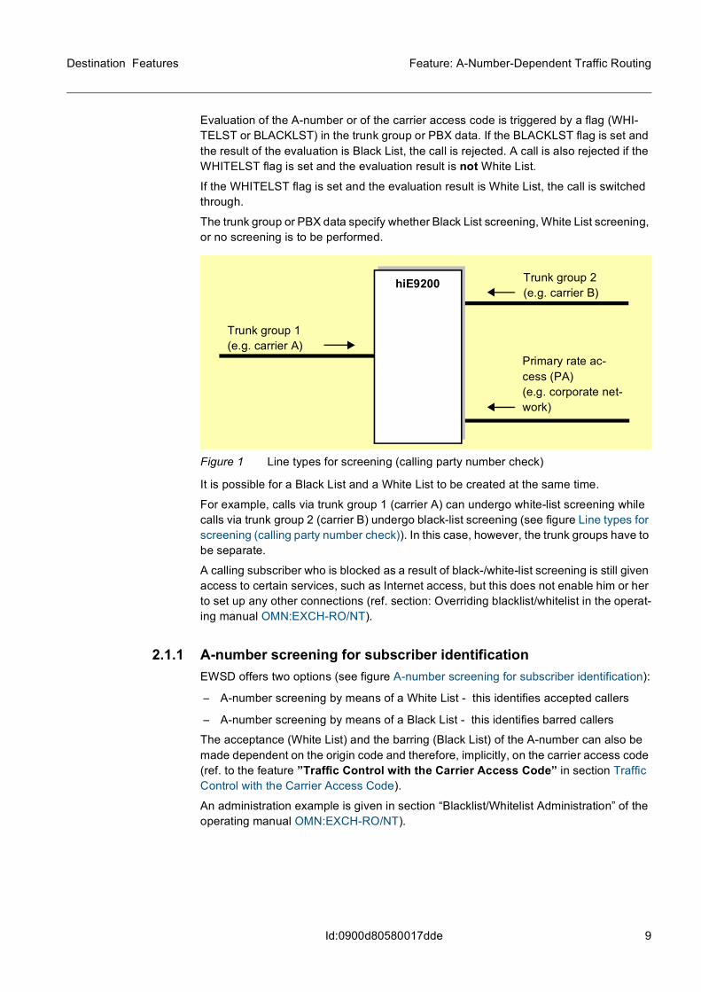
Evaluation of the A-number or of the carrier access code is triggered by a flag (WHI-TELST or BLACKLST) in the trunk group or PBX data. If the BLACKLST flag is set and the result of the evaluation is Black List, the call is rejected. A call is also rejected if the WHITELST flag is set and the evaluation result is not White List.
If the WHITELST flag is set and the evaluation result is White List, the call is switched through.
The trunk group or PBX data specify whether Black List screening, White List screening, or no screening is to be performed.
Figure 1 Line types for screening (calling party number check)
It is possible for a Black List and a White List to be created at the same time.
For example, calls via trunk group 1 (carrier A) can undergo white-list screening while calls via trunk group 2 (carrier B) undergo black-list screening (see figure Line types for screening (calling party number check)). In this case, however, the trunk groups have to be separate.
A calling subscriber who is blocked as a result of black-/white-list screening is still given access to certain services, such as Internet access, but this does not enable him or her to set up any other connections (ref. section: Overriding blacklist/whitelist in the operat-ing manual OMN:EXCH-RO/NT).
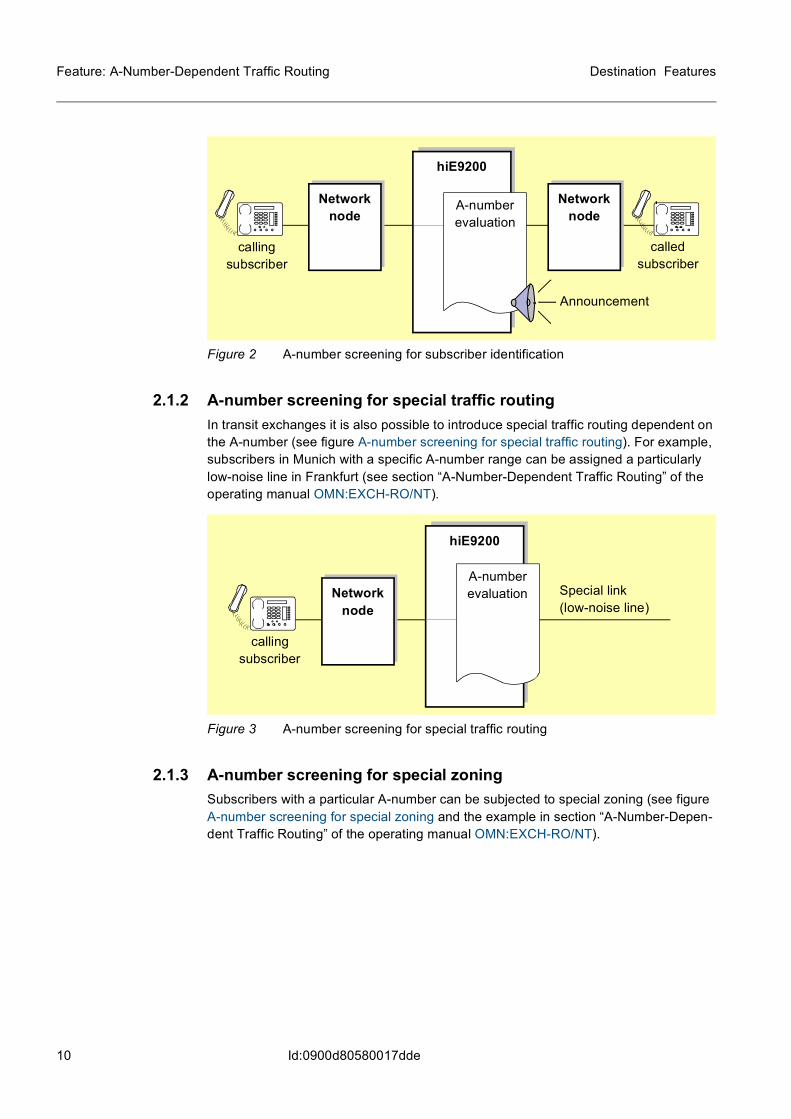
2.1.1 A-number screening for subscriber identificationEWSD offers two options (see figure A-number screening for subscriber identification):
– A-number screening by means of a White List - this identifies accepted callers
– A-number screening by means of a Black List - this identifies barred callers
The acceptance (White List) and the barring (Black List) of the A-number can also be made dependent on the origin code and therefore, implicitly, on the carrier access code (ref. to the feature ”Traffic Control with the Carrier Access Code” in section Traffic Control with the Carrier Access Code).
An administration example is given in section “Blacklist/Whitelist Administration” of the operating manual OMN:EXCH-RO/NT).
Trunk group 1(e.g. carrier A)
Trunk group 2(e.g. carrier B)
Primary rate ac-cess (PA)(e.g. corporate net-work)
hiE9200
10
Destination Features
Id:0900d80580017dde
Feature: A-Number-Dependent Traffic Routing
Figure 2 A-number screening for subscriber identification
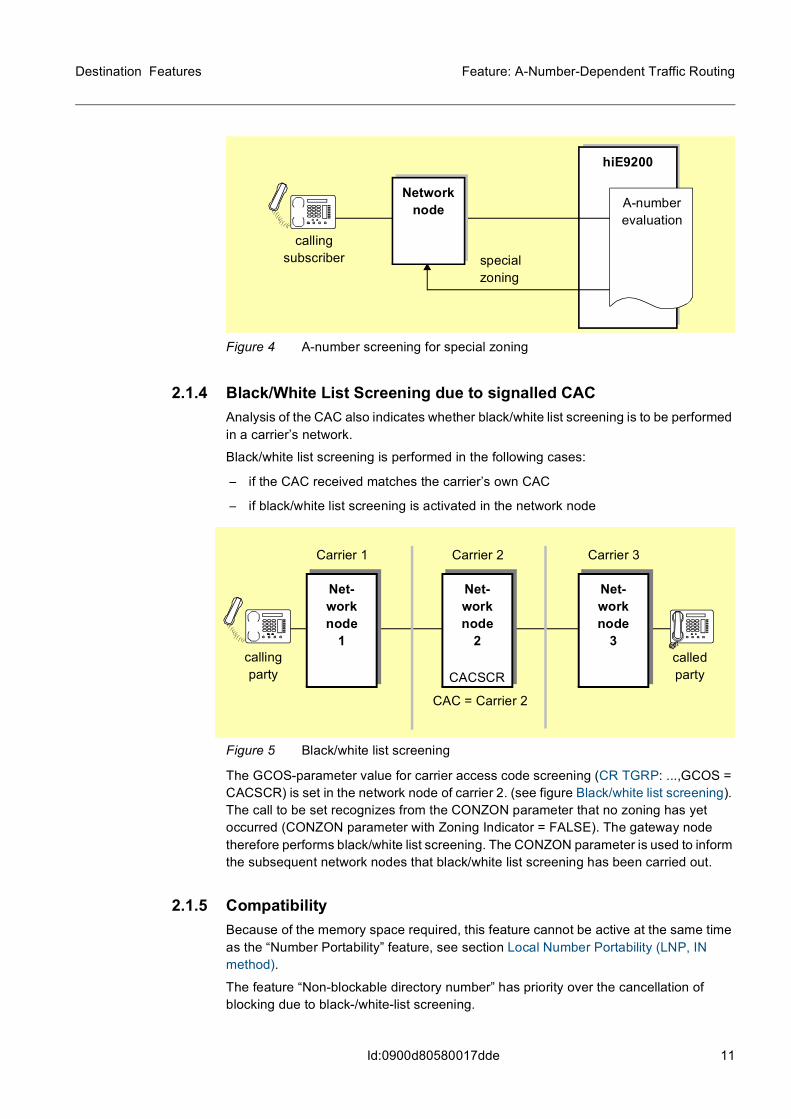
2.1.2 A-number screening for special traffic routingIn transit exchanges it is also possible to introduce special traffic routing dependent on the A-number (see figure A-number screening for special traffic routing). For example, subscribers in Munich with a specific A-number range can be assigned a particularly low-noise line in Frankfurt (see section “A-Number-Dependent Traffic Routing” of the operating manual OMN:EXCH-RO/NT).
Figure 3 A-number screening for special traffic routing
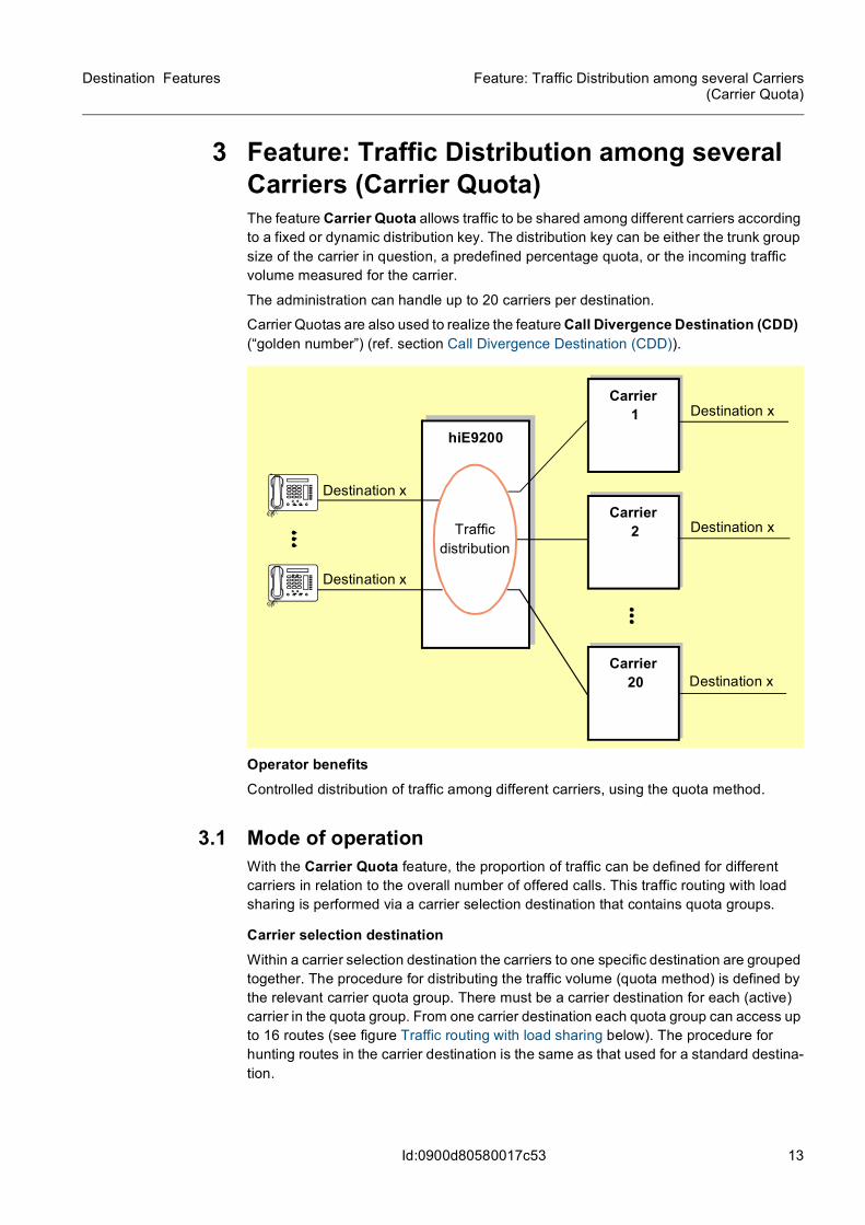
2.1.3 A-number screening for special zoningSubscribers with a particular A-number can be subjected to special zoning (see figure A-number screening for special zoning and the example in section “A-Number-Depen-dent Traffic Routing” of the operating manual OMN:EXCH-RO/NT).
hiE9200
Network node
A-number evaluation
Announcement
Network node
calling subscriber
called subscriber
hiE9200
Network node
A-numberevaluation Special link
(low-noise line)
calling subscriber
11
Destination Features Feature: A-Number-Dependent Traffic Routing
Id:0900d80580017dde
Figure 4 A-number screening for special zoning
2.1.4 Black/White List Screening due to signalled CACAnalysis of the CAC also indicates whether black/white list screening is to be performed in a carrier’s network.
Black/white list screening is performed in the following cases:
– if the CAC received matches the carrier’s own CAC
– if black/white list screening is activated in the network node
Figure 5 Black/white list screening
The GCOS-parameter value for carrier access code screening (CR TGRP: ...,GCOS = CACSCR) is set in the network node of carrier 2. (see figure Black/white list screening). The call to be set recognizes from the CONZON parameter that no zoning has yet occurred (CONZON parameter with Zoning Indicator = FALSE). The gateway node therefore performs black/white list screening. The CONZON parameter is used to inform the subsequent network nodes that black/white list screening has been carried out.
2.1.5 CompatibilityBecause of the memory space required, this feature cannot be active at the same time as the “Number Portability” feature, see section Local Number Portability (LNP, IN method).
The feature “Non-blockable directory number” has priority over the cancellation of blocking due to black-/white-list screening.
hiE9200
special zoning
Network node A-number
evaluationcalling
subscriber
called party
calling party
Net-work node
1
Carrier 1
Net-work node
2
Carrier 2
Net-work node
3
Carrier 3
CAC = Carrier 2
CACSCR

12
Destination Features
Id:0900d80580017dde
Feature: A-Number-Dependent Traffic Routing
2.1.6 RequirementsNo additional hardware is needed.
2.2 AdministrationThe operator can perform all administration functions on the NetManager by means of user-friendly applications or MML commands.
For information on the administration of A-Number-Dependent Traffic Routing (command path ORIGROZO) please refer to OMN:EXCH-RO/NT.
13
Destination Features Feature: Traffic Distribution among several Carriers(Carrier Quota)
Id:0900d80580017c53
3 Feature: Traffic Distribution among several Carriers (Carrier Quota)The feature Carrier Quota allows traffic to be shared among different carriers according to a fixed or dynamic distribution key. The distribution key can be either the trunk group size of the carrier in question, a predefined percentage quota, or the incoming traffic volume measured for the carrier.
The administration can handle up to 20 carriers per destination.
Carrier Quotas are also used to realize the feature Call Divergence Destination (CDD) (“golden number”) (ref. section Call Divergence Destination (CDD)).
Operator benefitsControlled distribution of traffic among different carriers, using the quota method.
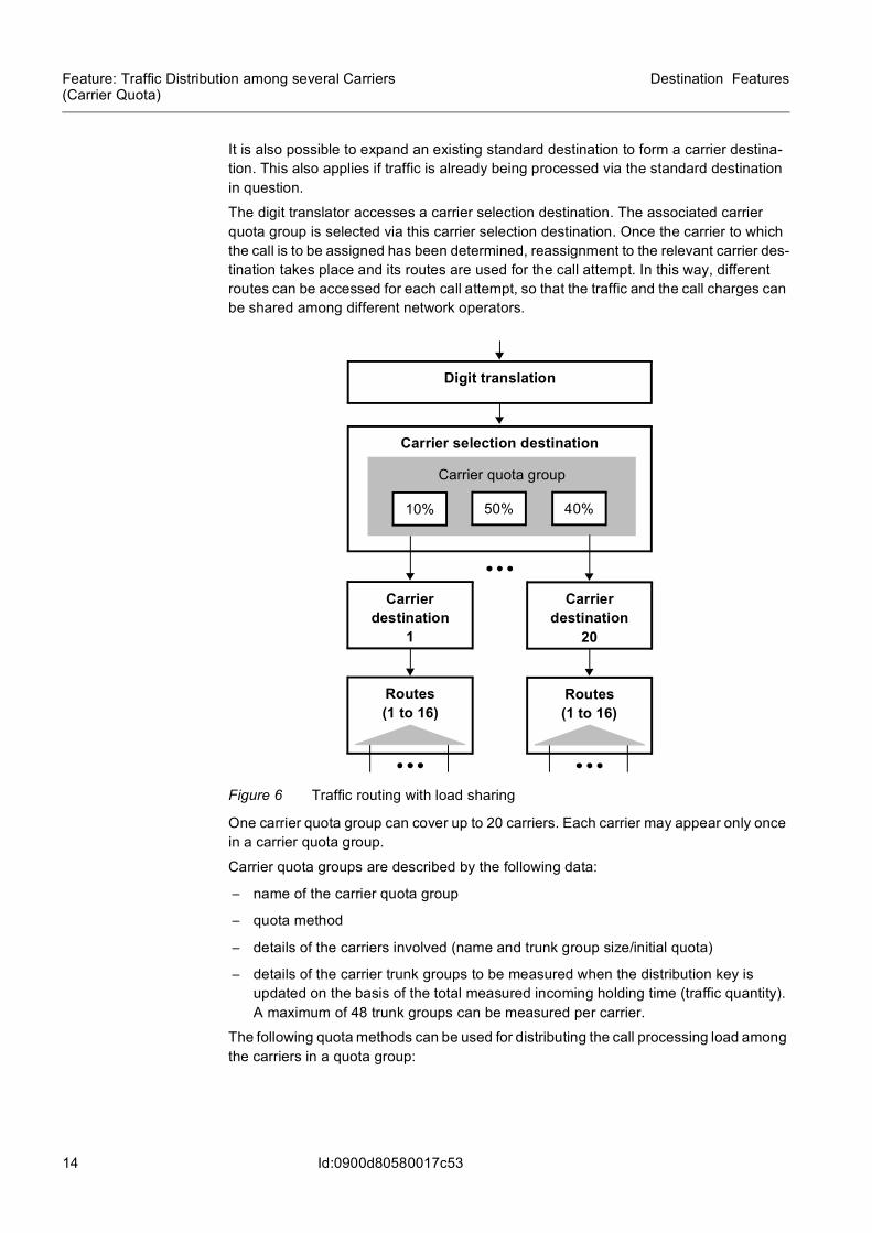
3.1 Mode of operationWith the Carrier Quota feature, the proportion of traffic can be defined for different carriers in relation to the overall number of offered calls. This traffic routing with load sharing is performed via a carrier selection destination that contains quota groups.
Carrier selection destinationWithin a carrier selection destination the carriers to one specific destination are grouped together. The procedure for distributing the traffic volume (quota method) is defined by the relevant carrier quota group. There must be a carrier destination for each (active) carrier in the quota group. From one carrier destination each quota group can access up to 16 routes (see figure Traffic routing with load sharing below). The procedure for hunting routes in the carrier destination is the same as that used for a standard destina-tion.
hiE9200
Carrier 1
Carrier 2
Carrier 20
Destination x
Destination x
Traffic distribution
Destination x
Destination x
Destination x
14
Destination Features
Id:0900d80580017c53
Feature: Traffic Distribution among several Carriers (Carrier Quota)
It is also possible to expand an existing standard destination to form a carrier destina-tion. This also applies if traffic is already being processed via the standard destination in question.
The digit translator accesses a carrier selection destination. The associated carrier quota group is selected via this carrier selection destination. Once the carrier to which the call is to be assigned has been determined, reassignment to the relevant carrier des-tination takes place and its routes are used for the call attempt. In this way, different routes can be accessed for each call attempt, so that the traffic and the call charges can be shared among different network operators.
Figure 6 Traffic routing with load sharing
One carrier quota group can cover up to 20 carriers. Each carrier may appear only once in a carrier quota group.
Carrier quota groups are described by the following data:
– name of the carrier quota group
– quota method
– details of the carriers involved (name and trunk group size/initial quota)
– details of the carrier trunk groups to be measured when the distribution key is updated on the basis of the total measured incoming holding time (traffic quantity). A maximum of 48 trunk groups can be measured per carrier.
The following quota methods can be used for distributing the call processing load among the carriers in a quota group:
Carrier selection destination
Routes (1 to 16)
Carrier destination
1
Carrier quota group
Routes (1 to 16)
Carrier destination
20
10% 50% 40%
Digit translation
15
Destination Features Feature: Traffic Distribution among several Carriers(Carrier Quota)
Id:0900d80580017c53
Load sharing based on trunk group size The trunk group size is the sum of all trunks in all the carrier's outgoing trunk groups from the home network node. The EWSD software converts trunk group sizes internally into fixed quotas. Outgoing call attempts are distributed among the individual carriers in pro-portion to the trunk group sizes entered for them.
Load sharing based on fixed quotas Outgoing call attempts are distributed among the individual carriers in proportion to the quota amounts entered for them.
The sum of the quotas of all carriers in the carrier quota group must be 100%. Any carrier with a quota of 0% is deactivated.
Load sharing with automatic adjustment to the carrier's incoming trafficThe outgoing call attempts are initially distributed among the individual carriers in pro-portion to the quotas entered for them. These remain valid until the first adjustment takes place following measurement of the total incoming call duration times for each carrier.
The trunk groups to be measured are incoming or bothway and are not entered in any other list of trunk groups to be measured. The incoming call duration times, added together on a trunk group-related basis, are analyzed every 15 minutes. This analysis forms the basis for updating the distribution key of the associated carrier quota group.
A prerequisite is that on the quarter-hour at least 9000 seconds of incoming call time have accumulated for the entire carrier quota group since the previous update. Further-more, only national calls are taken into consideration. International transit traffic is not measured. In addition, the method may only be used on one side of the connection, oth-erwise a stable quota distribution is established in which a single carrier is assigned 100% of the load.
A carrier with an initial quota of 0%, or a dynamically determined quota of 0%, is deac-tivated. However, these carriers are always taken into account in the measurement. If appropriate measurement data relating to these carriers is received, they are reacti-vated at the time of updating.
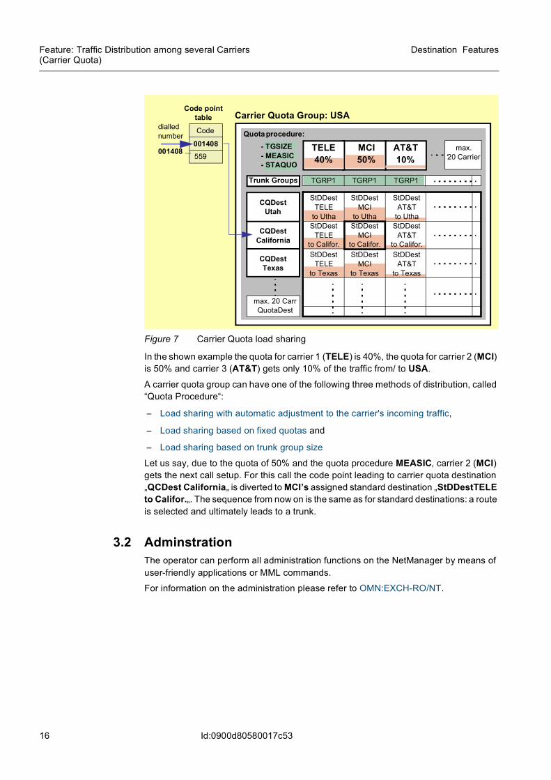
3.1.1 Example of a call setup using the feature Carrier Selection via Quota GroupsFor example, let us say that there are three long-distance carriers (MCI, TELE and AT&T) to route calls from Europe to the US and vice-versa.
In the figure Carrier Quota load sharing below, a code point 001408 leads to the Desti-nation CQDestCalifornia. The destination CQDestCalifornia is part of the Carrier Quota Group USA. For it is part of a Carrier Quota group is denoted as a Carrier Quota destination.
16
Destination Features
Id:0900d80580017c53
Feature: Traffic Distribution among several Carriers (Carrier Quota)
Figure 7 Carrier Quota load sharing
In the shown example the quota for carrier 1 (TELE) is 40%, the quota for carrier 2 (MCI) is 50% and carrier 3 (AT&T) gets only 10% of the traffic from/ to USA.
A carrier quota group can have one of the following three methods of distribution, called “Quota Procedure“:
– Load sharing with automatic adjustment to the carrier's incoming traffic,
– Load sharing based on fixed quotas and
– Load sharing based on trunk group size
Let us say, due to the quota of 50% and the quota procedure MEASIC, carrier 2 (MCI) gets the next call setup. For this call the code point leading to carrier quota destination „QCDest California„ is diverted to MCI’s assigned standard destination „StDDestTELE to Califor.„. The sequence from now on is the same as for standard destinations: a route is selected and ultimately leads to a trunk.
3.2 AdminstrationThe operator can perform all administration functions on the NetManager by means of user-friendly applications or MML commands.
For information on the administration please refer to OMN:EXCH-RO/NT.
CQDest California
CQDest Texas
CQDest Utah
Code point table
Code
001408559
dialled number
max. 20 Carr QuotaDest
max. 20 Carrier
Carrier Quota Group: USA
StDDestTELE
to Utha
StDDestMCI
to Utha
StDDestAT&T
to UthaStDDest
TELE to Califor.
StDDestMCI
to Califor.
StDDestAT&T
to Califor.StDDest
TELEto Texas
StDDestMCI
to Texas
StDDestAT&T
to Texas
TELE40%
MCI50%
AT&T10%
Trunk Groups TGRP1 TGRP1 TGRP1
Quota procedure: - TGSIZE - MEASIC - STAQUO
001408 ...
17
Destination Features Feature: Call Divergence Destination (CDD)
Id:0900d80580017c62
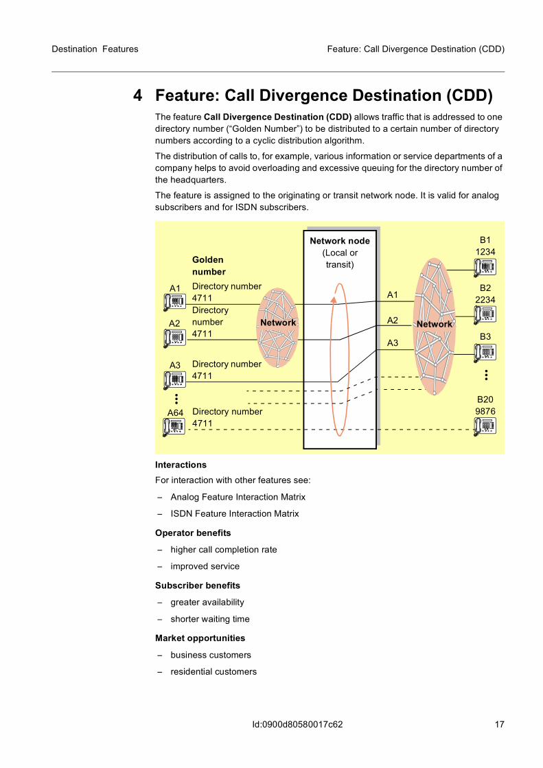
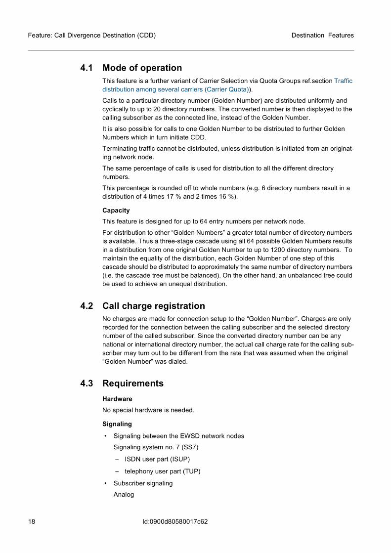
4 Feature: Call Divergence Destination (CDD)The feature Call Divergence Destination (CDD) allows traffic that is addressed to one directory number (“Golden Number”) to be distributed to a certain number of directory numbers according to a cyclic distribution algorithm.
The distribution of calls to, for example, various information or service departments of a company helps to avoid overloading and excessive queuing for the directory number of the headquarters.
The feature is assigned to the originating or transit network node. It is valid for analog subscribers and for ISDN subscribers.
InteractionsFor interaction with other features see:
– Analog Feature Interaction Matrix
– ISDN Feature Interaction Matrix
Operator benefits
– higher call completion rate
– improved service
Subscriber benefits
– greater availability
– shorter waiting time
Market opportunities
– business customers
– residential customers
Network node(Local or transit)
A1
A2
A3
B1 1234
B2 2234
B3
B20 9876
Directory number 4711Directory number 4711
Directory number 4711
A1
A2
A3
Golden number
A64 Directory number 4711
Network Network
18
Destination Features
Id:0900d80580017c62
Feature: Call Divergence Destination (CDD)
4.1 Mode of operationThis feature is a further variant of Carrier Selection via Quota Groups ref.section Traffic distribution among several carriers (Carrier Quota)).
Calls to a particular directory number (Golden Number) are distributed uniformly and cyclically to up to 20 directory numbers. The converted number is then displayed to the calling subscriber as the connected line, instead of the Golden Number.
It is also possible for calls to one Golden Number to be distributed to further Golden Numbers which in turn initiate CDD.
Terminating traffic cannot be distributed, unless distribution is initiated from an originat-ing network node.
The same percentage of calls is used for distribution to all the different directory numbers.
This percentage is rounded off to whole numbers (e.g. 6 directory numbers result in a distribution of 4 times 17 % and 2 times 16 %).
CapacityThis feature is designed for up to 64 entry numbers per network node.
For distribution to other “Golden Numbers” a greater total number of directory numbers is available. Thus a three-stage cascade using all 64 possible Golden Numbers results in a distribution from one original Golden Number to up to 1200 directory numbers. To maintain the equality of the distribution, each Golden Number of one step of this cascade should be distributed to approximately the same number of directory numbers (i.e. the cascade tree must be balanced). On the other hand, an unbalanced tree could be used to achieve an unequal distribution.
4.2 Call charge registrationNo charges are made for connection setup to the “Golden Number”. Charges are only recorded for the connection between the calling subscriber and the selected directory number of the called subscriber. Since the converted directory number can be any national or international directory number, the actual call charge rate for the calling sub-scriber may turn out to be different from the rate that was assumed when the original “Golden Number” was dialed.
4.3 RequirementsHardwareNo special hardware is needed.
Signaling
• Signaling between the EWSD network nodes
Signaling system no. 7 (SS7)
– ISDN user part (ISUP)
– telephony user part (TUP)
• Subscriber signaling
Analog
19
Destination Features Feature: Call Divergence Destination (CDD)
Id:0900d80580017c62
– dual-tone multi-frequency (DTMF)
– pulse dialing
ISDN
– digital subscriber signaling system no.1 (DSS1)
Subscriber interfacesThe following interfaces for subscriber access are required:
– DLU
– LTG
– V5.1 interface
– V5.2 interface
4.4 Administration The operator can perform all administration functions on the NetManager by means of user-friendly applications or MML commands.
For information on the administration please refer to section Call Divergence Destination (CDD) of the OMN:EXCH-RO/NT.
20
Destination Features
Id:0900d80580017ce5
Feature: Destination Areas with Transmission-Opti-mized Routing (TMR/IPI)
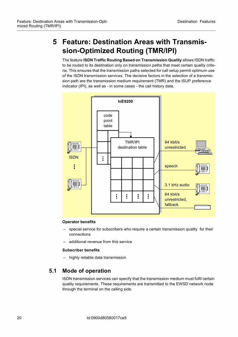
5 Feature: Destination Areas with Transmis-sion-Optimized Routing (TMR/IPI)The feature ISDN Traffic Routing Based on Transmission Quality allows ISDN traffic to be routed to its destination only on transmission paths that meet certain quality crite-ria. This ensures that the transmission paths selected for call setup permit optimum use of the ISDN transmission services. The decisive factors in the selection of a transmis-sion path are the transmission medium requirement (TMR) and the ISUP preference indicator (IPI), as well as - in some cases - the call history data.
Operator benefits
– special service for subscribers who require a certain transmission quality for their connections
– additional revenue from this service
Subscriber benefits
– highly reliable data transmission
5.1 Mode of operationISDN transmission services can specify that the transmission medium must fulfil certain quality requirements. These requirements are transmitted to the EWSD network node through the terminal on the calling side.
hiE9200
code point table
TMR/IPI destination table
ISDN
64 kbit/s unrestricted
speech
3.1 kHz audio
64 kbit/s unrestricted, fallback
21
Destination Features Feature: Destination Areas with Transmission-Opti-mized Routing (TMR/IPI)
Id:0900d80580017ce5
The requirements consist of:
– the transmission medium requirement (TMR)
– the ISUP preference indicator (IPI)
The TMR value indicates the required quality of the transmission link. The IPI value states whether or not the connection is to be routed in the ISDN network over the entire distance.
The call history values are only used if the calling side has specified routing require-ments that deviate from a pure TMR/IPI combination without call history reference.
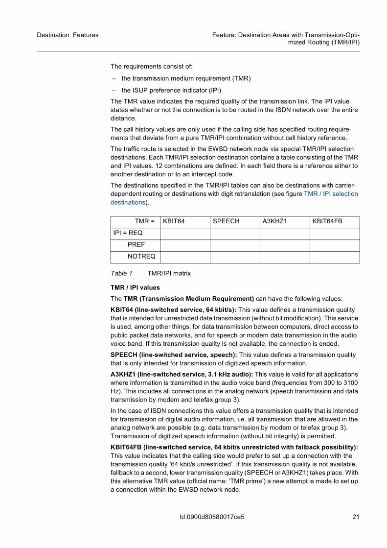
The traffic route is selected in the EWSD network node via special TMR/IPI selection destinations. Each TMR/IPI selection destination contains a table consisting of the TMR and IPI values. 12 combinations are defined. In each field there is a reference either to another destination or to an intercept code.
The destinations specified in the TMR/IPI tables can also be destinations with carrier-dependent routing or destinations with digit retranslation (see figure TMR / IPI selection destinations).
TMR / IPI valuesThe TMR (Transmission Medium Requirement) can have the following values:
KBIT64 (line-switched service, 64 kbit/s): This value defines a transmission quality that is intended for unrestricted data transmission (without bit modification). This service is used, among other things, for data transmission between computers, direct access to public packet data networks, and for speech or modem data transmission in the audio voice band. If this transmission quality is not available, the connection is ended.
SPEECH (line-switched service, speech): This value defines a transmission quality that is only intended for transmission of digitized speech information.
A3KHZ1 (line-switched service, 3.1 kHz audio): This value is valid for all applications where information is transmitted in the audio voice band (frequencies from 300 to 3100 Hz). This includes all connections in the analog network (speech transmission and data transmission by modem and telefax group 3).
In the case of ISDN connections this value offers a transmission quality that is intended for transmission of digital audio information, i.e. all transmission that are allowed in the analog network are possible (e.g. data transmission by modem or telefax group 3). Transmission of digitized speech information (without bit integrity) is permitted.
KBIT64FB (line-switched service, 64 kbit/s unrestricted with fallback possibility): This value indicates that the calling side would prefer to set up a connection with the transmission quality ’64 kbit/s unrestricted’. If this transmission quality is not available, fallback to a second, lower transmission quality (SPEECH or A3KHZ1) takes place. With this alternative TMR value (official name: ’TMR prime’) a new attempt is made to set up a connection within the EWSD network node.
TMR = KBIT64 SPEECH A3KHZ1 KBIT64FB
IPI = REQ
PREF
NOTREQ
Table 1 TMR/IPI matrix
22
Destination Features
Id:0900d80580017ce5
Feature: Destination Areas with Transmission-Opti-mized Routing (TMR/IPI)
The IPI (ISDN User Part Preference Indicator) can have the following values:
REQ (required): This value states that the entire connection between calling subscriber and called subscriber must be routed in the ISDN network, so as to guarantee the nec-essary transmission and signaling qualities.
PREF (preferred): This value states that the entire connection between calling sub-scriber and called subscriber should preferably be routed in the ISDN network, so as to guarantee the best possible transmission and signaling qualities.
NOTREQ (not required): This value states that it is not necessary for the connection to be routed in the ISDN network because the analog network also guarantees an adequate transmission and signaling quality.
Selection of a TMR / IPI selection destinationTMR/IPI selection destinations are accessed via one or more code points. Each selec-tion destination refers to subsequent destinations via which routing arrives at the relevant outgoing trunk group (see figure Traffic routing via a TMR/IPI selection destina-tion).
Up to 16 routes can be accessed via a TMR/IPI destination.
A TMR/IPI selection destination consists of an address component and a data compo-nent.
Address component:
– TMR/IPI selection destination
– TMR/IPI combination (optionally with call history data)
Data component:
– TMR/IPI destination 1 ... n
23
Destination Features Feature: Destination Areas with Transmission-Opti-mized Routing (TMR/IPI)
Id:0900d80580017ce5
Figure 8 Traffic routing via a TMR/IPI selection destination
Each TMR/IPI combination is assigned precisely one TMR/IPI destination. Destinations can be accessed via different TMR/IPI combinations.
The calling end normally requests one TMR/IPI combination. If it is not possible to access a destination that corresponds to the TMR/IPI data, a backward signal informs the calling side whether a destination is available for the required ISDN preference indi-cator (IPI) for at least one other TMR value (see figure TMR / IPI selection destinations).
TMR/IPI selection destinationThe traffic is distributed to various destinations in accor-dance with the TMR/IPI data. A tone or announcement is applied for TMR/IP data with-out a valid destination.
Routes (1 to 16)
Digit translation
TMR/IPI destination
1
Routes (1 to 16)
TMR/IPI destination
n
24
Destination Features
Id:0900d80580017ce5
Feature: Destination Areas with Transmission-Opti-mized Routing (TMR/IPI)
Figure 9 TMR / IPI selection destinations
If an appropriate destination is available, the backward signal contains the information that switchover to a different transmission medium can be successful for the same IPI. In all other cases the backward signal informs the calling side that a connection with the required ISDN preference indicator is not possible in the selected direction.
Only digital terminal equipment can evaluate the backward signal; for this reason, the connection is simultaneously diverted to an intercept code that provides services and analog terminal equipment with an announcement or special information tone. This means, for example, that ISDN telephones receive two parallel responses for services such as “Telephony” and “7 kHz telephony”, namely backward signal and intercept code.
Code
Dialed number 1234567
Destination: TMR1
Dest
1234 TMR1
Route no. TGRP
1 tgrp1
2 tgrp2
Destination: T13
3 tgrp3Standard destinations
Code point table
TMR/IPI destinations
Carrier Dest
1 1
2 2
Destination: T23Carrier quota group: group 1
3 3
Destinations with carrier selection
Back to digit analysis
Destination: TxxDestination with retranslation
KB 64 T11
Speech T21
T12 T13
T22 T23
Required Preferred Not Re-quired
25
Destination Features Feature: Destination Areas with Transmission-Opti-mized Routing (TMR/IPI)
Id:0900d80580017ce5
Provided it has suitable terminal equipment, the calling end can also request a double combination (TMR + TMR prime)/IPI. The first TMR value represents the preferred transmission medium; the second value (TMR prime) represents a lower-quality trans-mission medium which is acceptable as a fallback alternative (e.g. TMR = 7 kHz tele-phony, TMR prime = 3.1 kHz audio, IPI = ISDN required).
If a destination corresponding to the preferred TMR/IPI data cannot be accessed for the connection, the EWSD network node attempts to use the alternative transmission medium.
If this second destination search is successful, a backward signal is sent to inform the calling end that the fallback is taking place. The calling side is therefore always aware of the transmission medium that is being used for through-connection.
If the second destination search is unsuccessful, the same procedure as for unsuccess-ful request of a single TMR/IPI combination is used: a backward signal is sent and, at the same time, the connection is diverted to an intercept code.
5.2 RequirementsNo additional hardware is needed.
5.3 AdministrationThe operator can perform all administration functions on the NetManager by means of user-friendly applications or MML commands.
For information on the administration please refer to OMN:EXCH-RO/NT.
26
Destination Features
Id:0900d80580017dbf
Feature: Hard to Reach Control (HTRC)
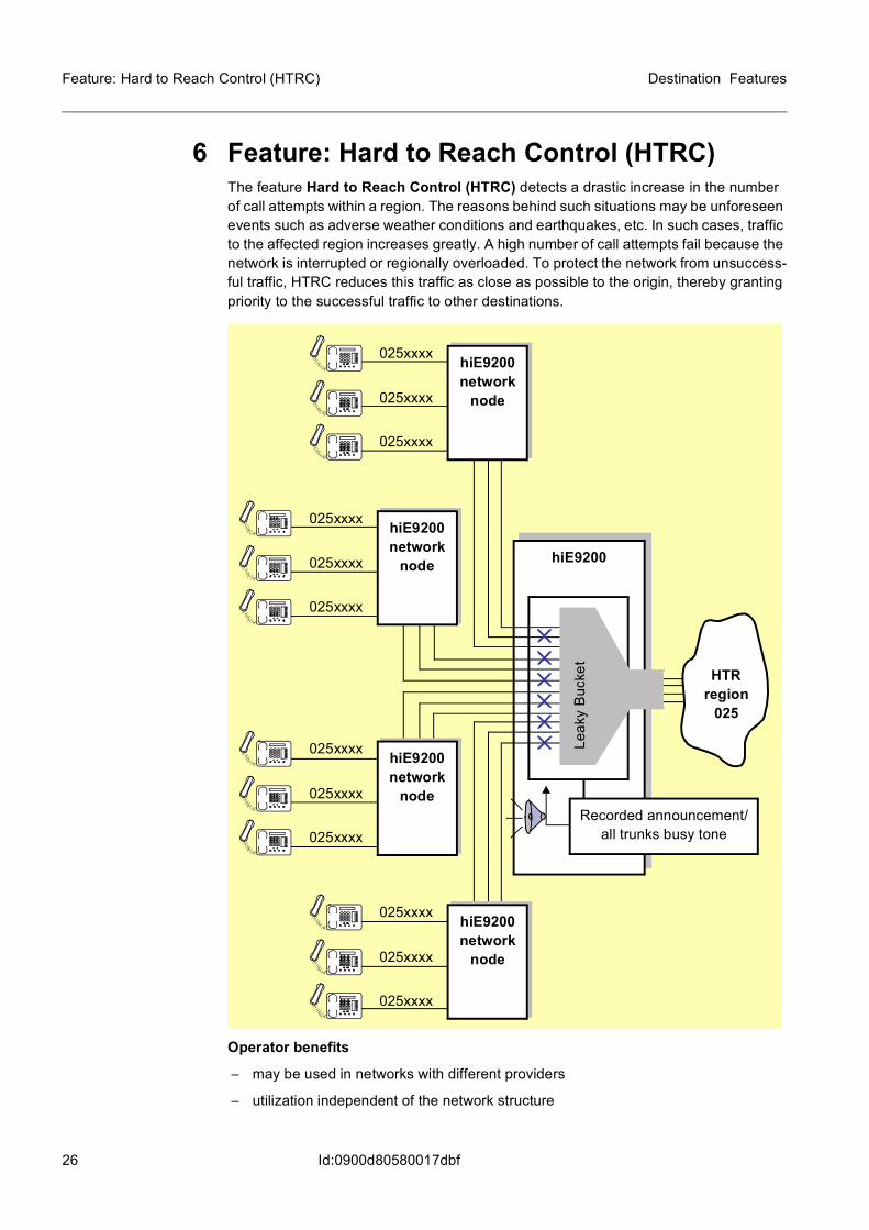
6 Feature: Hard to Reach Control (HTRC)The feature Hard to Reach Control (HTRC) detects a drastic increase in the number of call attempts within a region. The reasons behind such situations may be unforeseen events such as adverse weather conditions and earthquakes, etc. In such cases, traffic to the affected region increases greatly. A high number of call attempts fail because the network is interrupted or regionally overloaded. To protect the network from unsuccess-ful traffic, HTRC reduces this traffic as close as possible to the origin, thereby granting priority to the successful traffic to other destinations.
Operator benefits
– may be used in networks with different providers
– utilization independent of the network structure
025xxxx
hiE9200
025xxxx
025xxxx
025xxxx
025xxxx
025xxxx
025xxxx
025xxxx
025xxxx
025xxxx
025xxxx
025xxxx
Leak
y B
ucke
t
HTRregion
025
hiE9200network
node
hiE9200network
node
hiE9200network
node
hiE9200network
nodeRecorded announcement/
all trunks busy tone
27
Destination Features Feature: Hard to Reach Control (HTRC)
Id:0900d80580017dbf
– monitoring of traffic to pre-defined destinations
– reduction in traffic to hard to reach destinations, thereby granting priority to the revenue-generating traffic not affected by the HTR situation
– EWSD-external network nodes are also supported by this feature
6.1 Mode of operationThe feature Hard to Reach Control (HTRC) grants priority to successful traffic to other destinations before the traffic to hard to reach destinations, which only has a small chance of being switched through. HTRC reduces the unsuccessful traffic as close as possible to the origin, thereby preventing regional congestion within the network.
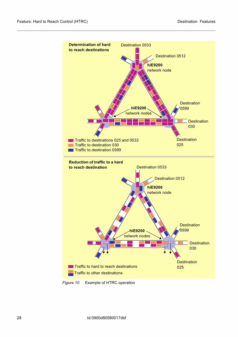
HTRC is characterized by the following functions (see also figure Example of HTRC operation below):
– automatic determination of the HTR status of pre-defined destinations in outgoing traffic
– automatic restriction of the traffic to hard to reach destinations through pre-defined network management measures, e.g. line reservation
Determination of hard to reach destinationsThe destinations to be observed by HTRC are placed on a monitoring list.
The number of seizures and the answer/seizure rate are evaluated every 5 minutes for the destinations on the monitoring list to be observed. In every 5-minute interval, the values ascertained are compared with their thresholds for the “minimum number of call attempts per time unit” and the “answer/seizure rate”. (Every destination has its own thresholds.)
A destination is regarded as hard to reach if the number of seizures per 5-minute interval corresponds at least to the threshold value for “minimum number of call attempts per time unit” and the corresponding “answer/seizure rate” is less than or equal to the threshold for the answer/seizure rate.
Once a hard to reach destination is detected, it is placed on the control list.
If a call request is made to a destination which is on the control list, a pre-determined network management measure (e.g. line reservation, “CANCEL TO”, “CANCEL FROM” or “SKIP”) is activated to reduce the traffic to this destination. Call requests rejected by means of network management measures are rerouted to a recorded announcement or receive the all trunks busy tone.
Destinations on the control list are monitored every 5 minutes. A destination is removed from the control list when its answer/seizure rate exceeds a certain threshold within 5 minutes. This does not apply to those destinations which have been placed on the control list manually. These are subject to neither monitoring nor determination of the HTR status.
A hysteresis factor prevents a destination from being removed from the control list too soon.
28
Destination Features
Id:0900d80580017dbf
Feature: Hard to Reach Control (HTRC)
Figure 10 Example of HTRC operation
hiE9200network node
Destination 025
Determination of hard to reach destinations
Destination 030
Destination 0533
Destination 0599
Destination 0512
Traffic to destinations 025 and 0533Traffic to destination 030Traffic to destination 0599
Destination 025
hiE9200network nodes
Reduction of traffic to a hard to reach destination
Destination 030
Destination 0533
Destination 0599
Destination 0512
Traffic to hard to reach destinationsTraffic to other destinations
hiE9200network nodes
hiE9200network node
29
Destination Features Feature: Hard to Reach Control (HTRC)
Id:0900d80580017dbf
Criteria for determination of hard to reach destinationsHTRC enables the following functions:
– Monitoring of defined destinations
– Monitoring and reduction of the traffic to defined destinations
– Reduction of the traffic to manually pre-defined destinations
The following values can be defined for determination of hard to reach destinations:
– Destinations to be monitored
– Minimum number of call attempts per 5-minute interval
– Minimum answer/seizure rate (ASR)
– HTRC function
Monitoring list
– Number of destinations to be monitored: ≤ 10 000 with ≤ 6 digits per destination
– Number of destinations to be monitored in detail: ≤ 500 with ≤ 15 digits per desti-nation
– Answer/seizure rate: 1 to 99%
– Number of call attempts: 1 to 65 535
Control list
– Number of destinations to be monitored: ≤ 10 000 with monitoring every 5 minutes or with manual input by operator without checking
Network management measures
– Line reservation
– CANCEL TO
– CANCEL FROM
– SKIP
Destinations
– Destination areas with up to 6 digits (e.g. 0-9, 010-019, 0200-0210, 03409-03441, etc.) can be entered by the operator, whereby each area has its own threshold for the answer/seizure rate and for the minimum number of call attempts. In order to observe the destination in more detail, the operator can enter specific digit combina-tions with up to 15 digits.
Monitoring of destination without control
– This makes it possible to monitor destinations without their being controlled (i.e. placed on the control list) as soon as they attain the hard to reach status.
Monitoring of destination with control
– This makes it possible for destinations to be monitored and also controlled (i.e. auto-matically placed on the control list) as soon as they attain the hard to reach status.
Control of destinations without monitoring
– Destinations can be explicitly placed on the control list and thereby subjected to the pre-defined network management measures.

30
Destination Features
Id:0900d80580017dbf
Feature: Hard to Reach Control (HTRC)
6.2 RequirementsNo additional hardware is needed.
6.3 Administration Hints and ExamplesThe operator can perform all administration functions on the NetManager by means of user-friendly applications or MML commands.
For information on the administration please refer to OMN:EXCH-RO/NT.
31
Destination Features Feature: Mass Call Control (MCC)
Id:0900d80580017ca2
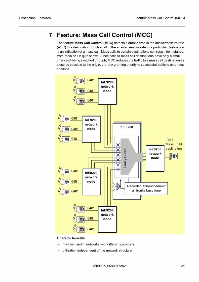
7 Feature: Mass Call Control (MCC)The feature Mass Call Control (MCC) detects a drastic drop in the answer/seizure rate (ASR) to a destination. Such a fall in the answer/seizure rate to a particular destination is an indication of a mass call. Mass calls to certain destinations can result, for instance, from radio or TV quiz shows. Since calls to mass call destinations have only a small chance of being switched through, MCC reduces the traffic to a mass call destination as close as possible to the origin, thereby granting priority to successful traffic to other des-tinations.
Operator benefits
– may be used in networks with different providers
– utilization independent of the network structure
0481
hiE9200
Recorded announcement/all trunks busy tone
0481 Mass calldestination
0481
0481
0481
hiE9200network
node
0481
0481
hiE9200network
node
0481
0481
0481
hiE9200network
node
0481
0481
0481
hiE9200network
node
hiE9200network
node
Leak
y Bu
cket
32
Destination Features
Id:0900d80580017ca2
Feature: Mass Call Control (MCC)
– monitoring of the entire directory number volume of the EWSD network node
– reduction in the traffic to directory numbers of mass call destinations, thereby granting priority to the revenue-generating traffic not affected by the MCC situation
– EWSD-external network nodes are also supported by this feature
7.1 Mode of operationThe Mass Call Control (MCC) feature grants priority to successful traffic before the traffic to mass call destinations, which has only a small chance of being switched through. MCC reduces the unsuccessful traffic as close as possible to the origin, thereby prevent-ing regional congestion in the network.
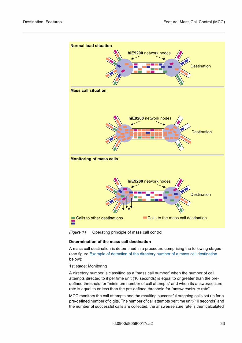
MCC is characterized by the following functions (see figure Operating principle of mass call control below):
• permanent monitoring of the answer/seizure rate for all calls in the network node
• automatic detection of a drastic drop in the answer/seizure rate as an indication of a mass call situation
• automatic identification of the directory number responsible for the mass calls
• reduction in the unsuccessful traffic to this directory number
The network management mechanism known as the “Leaky Bucket“ principle is used for automatic reduction of the unsuccessful traffic.
33
Destination Features Feature: Mass Call Control (MCC)
Id:0900d80580017ca2
Figure 11 Operating principle of mass call control
Determination of the mass call destinationA mass call destination is determined in a procedure comprising the following stages (see figure Example of detection of the directory number of a mass call destination below):
1st stage: Monitoring
A directory number is classified as a “mass call number” when the number of call attempts directed to it per time unit (10 seconds) is equal to or greater than the pre-defined threshold for “minimum number of call attempts” and when its answer/seizure rate is equal to or less than the pre-defined threshold for “answer/seizure rate”.
MCC monitors the call attempts and the resulting successful outgoing calls set up for a pre-defined number of digits. The number of call attempts per time unit (10 seconds) and the number of successful calls are collected; the answer/seizure rate is then calculated
Normal load situation
hiE9200 network nodes
Destination
Mass call situation
hiE9200 network nodes
Destination
hiE9200 network nodes
Destination
Monitoring of mass calls
Calls to the mass call destinationCalls to other destinations
34
Destination Features
Id:0900d80580017ca2
Feature: Mass Call Control (MCC)
and compared with the pre-defined thresholds for “minimum number of call attempts” and “answer/seizure rate”.
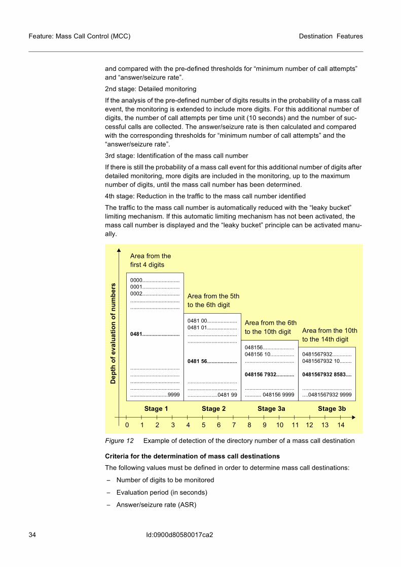
2nd stage: Detailed monitoring
If the analysis of the pre-defined number of digits results in the probability of a mass call event, the monitoring is extended to include more digits. For this additional number of digits, the number of call attempts per time unit (10 seconds) and the number of suc-cessful calls are collected. The answer/seizure rate is then calculated and compared with the corresponding thresholds for “minimum number of call attempts” and the “answer/seizure rate”.
3rd stage: Identification of the mass call number
If there is still the probability of a mass call event for this additional number of digits after detailed monitoring, more digits are included in the monitoring, up to the maximum number of digits, until the mass call number has been determined.
4th stage: Reduction in the traffic to the mass call number identified
The traffic to the mass call number is automatically reduced with the “leaky bucket” limiting mechanism. If this automatic limiting mechanism has not been activated, the mass call number is displayed and the “leaky bucket” principle can be activated manu-ally.
Figure 12 Example of detection of the directory number of a mass call destination
Criteria for the determination of mass call destinationsThe following values must be defined in order to determine mass call destinations:
– Number of digits to be monitored
– Evaluation period (in seconds)
– Answer/seizure rate (ASR)
Area from the 5th to the 6th digit
Area from the first 4 digits
Area from the 6th to the 10th digit Area from the 10th
to the 14th digit
Stage 1 Stage 3a Stage 3bStage 2
Dep
th o
f eva
luat
ion
of n
umbe
rs
0000.........................0001.........................0002...........................................................................................
0481.........................
.................................
.................................
.................................
.................................
.........................9999
0481 00....................0481 01......................................................................................
0481 56....................
.................................
.................................
....................0481 99
048156.....................048156 10.................................................
048156 7932............
.................................
........... 048156 9999
0481567932.............0481567932 10........
0481567932 8583....
.................................
....0481567932 9999
0 13 1411 129 107 85 63 41 2
35
Destination Features Feature: Mass Call Control (MCC)
Id:0900d80580017ca2
– Minimum number of call attempts in the evaluation period
The values can be defined within the following limits:
– Answer/seizure rate: 0 to 99%
– Minimum number of call attempts per 10 seconds: 30 to 1000
– Call reduction time: 2 to 10 minutes, in increments of 2 minutes
– Time for determining the mass call destination: ≤ 60 seconds
– Number of digits to be monitored (including the national dialing prefix): 6 to 14
– Start of call reduction: not before the mass call destination has been determined
– File: sequential, daily file At least 2000 mass call events can be stored.
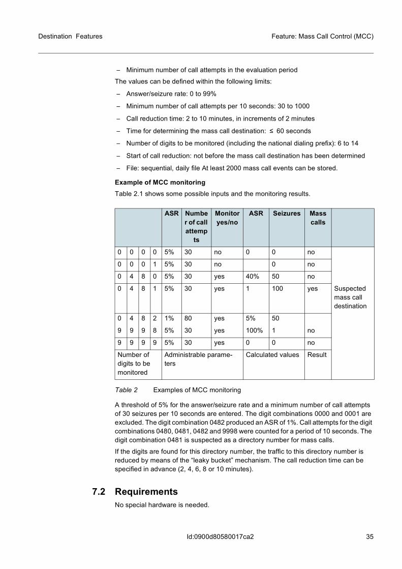
Example of MCC monitoringTable 2.1 shows some possible inputs and the monitoring results.
A threshold of 5% for the answer/seizure rate and a minimum number of call attempts of 30 seizures per 10 seconds are entered. The digit combinations 0000 and 0001 are excluded. The digit combination 0482 produced an ASR of 1%. Call attempts for the digit combinations 0480, 0481, 0482 and 9998 were counted for a period of 10 seconds. The digit combination 0481 is suspected as a directory number for mass calls.
If the digits are found for this directory number, the traffic to this directory number is reduced by means of the “leaky bucket” mechanism. The call reduction time can be specified in advance (2, 4, 6, 8 or 10 minutes).
7.2 RequirementsNo special hardware is needed.
ASR Number of call attemp
ts
Monitor yes/no
ASR Seizures Mass calls
0 0 0 0 5% 30 no 0 0 no
0 0 0 1 5% 30 no 0 no
0 4 8 0 5% 30 yes 40% 50 no
0 4 8 1 5% 30 yes 1 100 yes Suspected mass call destination
0 4 8 2 1% 80 yes 5% 50
9 9 9 8 5% 30 yes 100% 1 no
9 9 9 9 5% 30 yes 0 0 no
Number of digits to be monitored
Administrable parame-ters
Calculated values Result
Table 2 Examples of MCC monitoring

36
Destination Features
Id:0900d80580017ca2
Feature: Mass Call Control (MCC)
7.3 AdministrationThe operator can perform all administration functions on the NetManager by means of user-friendly applications or MML commands.
For information on the administration please refer to OMN:EXCH-RO/NT.