DERM 941 † DERM 942 · 2017-02-16 · To promote the safe use of the Bovie® DERM 941/942 High...
22
DERM 941 • DERM 942 High-Frequency Desiccators User’s Guide
Transcript of DERM 941 † DERM 942 · 2017-02-16 · To promote the safe use of the Bovie® DERM 941/942 High...
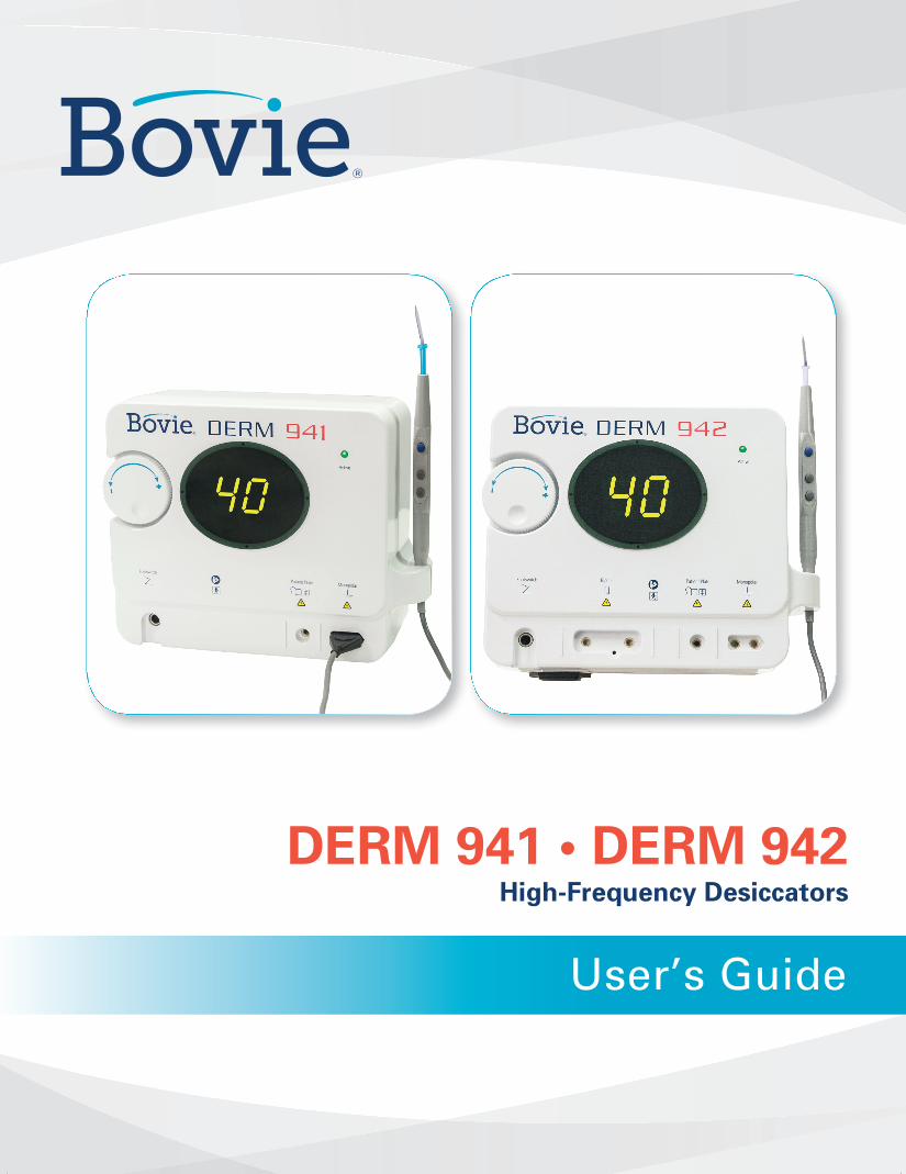
DERM 941 • DERM 942High-Frequency Desiccators
User’s Guide

1User ’s Guide • DERM 941 / 942
USER’S GUIDE

TABLE OF CONTENTSIntroduction..................................................................................................................................................3
Operating Principle ...................................................................................................................................3
Safety...............................................................................................................................................................3
Introduction..................................................................................................................................................3
Warnings and Cautions ............................................................................................................................3
Contraindications .......................................................................................................................................6
Catalog Numbers........................................................................................................................................6
Application Specification.........................................................................................................................6
Unit Operation.............................................................................................................................................8
Inspecting the Desiccator and Accessories ......................................................................................8
Setup Procedures .......................................................................................................................................9
Performance Checks ...............................................................................................................................11
Maintenance ..............................................................................................................................................11
Sterilization and Cleaning of the Accessories ...............................................................................11
Accessories .................................................................................................................................................11
Technical Description.............................................................................................................................11
IEC Classifications.....................................................................................................................................12
EMC Compliance ......................................................................................................................................13
Warranty ......................................................................................................................................................15
Servicing and Repair ...............................................................................................................................15
Troubleshooting.......................................................................................................................................16
Output Power Characteristics .............................................................................................................17
Graphs ..........................................................................................................................................................18
Descriptions of Symbols........................................................................................................................20
2 Bovie Medical Corporat ion

INTRODUCTIONThank you for purchasing the Bovie® DERM 941/942. Please visually check the unit to ensure that damage didnot occur during shipment and that all standard items are included. If there are any discrepancies, pleasecontact Bovie® at +1-727-384-2323. For the latest user information and technical bulletins, visitwww.boviemed.com.
OPERATING PRINCIPLERF energy is generated and passed through an interconnecting cable to an accessory, where the energy isdelivered to coagulate and desiccate tissue.
SAFETYThe safe and effective use of electrosurgery depends to a large degree on factors solely under the control of the operator. There is no substitute for a properly trained and vigilant medical staff. It is important that theyread, understand, and follow the operating instructions supplied with this electrosurgical equipment.
Physicians have used electrosurgical equipment safely in numerous procedures. Before starting any surgicalprocedure, the surgeon should be familiar with the medical literature, complications, and hazards of usingelectrosurgery in that procedure.
To promote the safe use of the Bovie® DERM 941/942 High Frequency Desiccator, this section presents thewarnings and cautions that appear throughout this user’s guide. So that you can operate this equipment withmaximum safety, it is important that you read, understand, and follow the instructions in these warnings andcautions. It is also important that you read, understand, and follow the instructions for use in this user’s guide.
Emergo EuropeMolenstraat 152513 BH, The HagueThe Netherlands
©2016 Bovie Medical Corporation. All rights reserved. Contents of this publication may not be reproducedwithout the written permission of Bovie Medical Corporation.
Bovie Part Number: MC-55-239-001 Rev. 0
WARNINGS AND CAUTIONSIn order to safely operate the Bovie® DERM 941/942, several precautions need to be followed.
WARNINGS:Hazardous Electrical Output - This equipment is for use only by trained, licensed physicians.
Danger: Fire / Explosion Hazard - Do not use the Bovie® DERM 941/942 in the presence offlammable materials.
Fire / Explosion Hazard - The following substances will contribute to increased fire and explosionhazards in the operating room: • Flammable substances (such as alcohol based skin prepping agents and tinctures) • Naturally occurring flammable gases which may accumulate in body cavities such as the bowel • Oxygen enriched atmospheres • Oxidizing agents (such as nitrous oxide [N20] atmospheres).The sparking and heating associated with electrosurgery can provide an ignition source. Observe fire precautions at all times. When using electrosurgery in the same room with any of these substances or gases, prevent their accumulation or pooling under surgical drapes, orwithin the area where electrosurgery is performed.
To avoid risk of electric shock, this equipment must only be connected to a supply mains withprotective earth.
3User ’s Guide • DERM 941 / 942

Connect the power cord to a properly polarized and grounded power source with the frequency andvoltage characteristics that match those listed on the back of the unit. Disconnect power cord frompower source or unplug the power cord from the unit’s power inlet to isolate the internal circuits fromthe supply mains.
WARNINGS:
Electric Shock Hazard - Connect the generator power cord to a properly grounded receptacle. Do notuse power plug adapters.
Electric Shock Hazard - Always turn off and unplug the generator before cleaning.
Fire Hazard - Do not use extension cords.
No modification of this equipment is allowed.
This equipment/system is intended for use by healthcare professionals only. This equipment/systemmay cause radio interference or may disrupt the operation of nearby equipment. It may be necessary totake mitigation measures, such as re-orienting or relocating the ME EQUIPMENT or ME SYSTEM orshielding the location.
Patient Safety - Use the generator following the directions described in the Setup Procedures.Otherwise, inaccurate power outputs may result.
Failure of the high frequency electrosurgical equipment could result in an unintended increase of outputpower.
The instrument receptacles on this generator are designed to accept only one instrument at a time. Donot attempt to connect more than one instrument at a time into a given receptacle. Doing so will causesimultaneous activation of the instruments.
Use the lowest output setting necessary to achieve the desired surgical effect. Use the active electrodeonly for the minimum time necessary in order to lessen the possibility of unintended burn injury.Pediatric applications and/or procedures performed on small anatomic structures may require reducedpower settings. The higher the current flow, and the longer the current is applied, the greater thepossibility of unintended thermal damage to tissue, especially during use on small structures.
Use electrosurgery with caution in the presence of internal or external devices such as pacemakers or pulse generators. Interference produced by the use of electrosurgical devices can causedevices such as pacemakers to enter an asynchronous mode or can block the pacemaker effectentirely. Consult the device manufacturer or hospital Cardiology Department for further information when use of electrosurgical appliances is planned for patients with cardiac pacemakers or other implantable devices.
If the patient has an Implantable Cardioverter Defibrillator (ICD), contact the ICD manufacturer forinstructions before performing an electrosurgical procedure. Electrosurgery may cause multipleactivation of ICDs.
Do not use electrosurgical equipment unless properly trained to use it in the specific procedure beingundertaken. Use by physicians without such training has resulted in serious, unintended patient injury,including bowel perforation and unintended, irreversible tissue necrosis.
For surgical procedures where the high frequency current could flow through parts of the body having arelatively small cross-sectional area, the use of bipolar techniques may be desirable to avoid unwantedcoagulation.
For all Monopolar modes, any associated equipment and active electrodes must be rated to with standthe combination of output voltage, vp-p and crest factor as stated in this manual.
Associated equipment and active accessories should be selected that have a rated accessory voltageequal to or greater than the maximum output voltage.
In some circumstances, potential exists for alternate site burns at points of skin contact (e.g., betweenthe arm and the side of the body). This occurs when electrosurgical current seeks a path to the returnelectrode that includes the skin-to-skin contact point. Current passing through small skin-to-skin contactpoints is concentrated and may cause a burn. This is true for grounded, ground referenced, and isolatedoutput generators.
4 Bovie Medical Corporat ion

To reduce the potential for alternate site burns, do one or more of the following: • Avoid skin-to-skin contact points, such as fingers touching leg, when positioning the patient. • Place 5 to 8 cm (2 to 3 in.) of dry gauze between contact points to ensure that contact does not occur. • Position the return electrode to provide a direct current route between the surgical site and the return electrode which avoids skin-to-skin contact areas. • In addition, place patient return electrodes according to the manufacturer’s instructions.Potential for alternate site burns increases if the return electrode is compromised. Bovie recommends theuse of split return electrodes and Bovie generators with a contact quality monitoring system.
Minor neuromuscular stimulation is possible when arcs between the ACTIVE ELECTRODE and tissue occur.The generator has been designed to minimize the possibility of neuromuscular stimulation.
The entire area of the neutral electrode (NE) should be reliably attached to the patient’s body and as close tothe operating field as possible. Refer to NE instructions for use.
The cables to surgical electrodes should be positioned in such a way that contact with the patient or otherleads is avoided. Temporarily unused active electrodes should be stored so that they are isolated from thepatient.
Do not wrap the accessory cords or return electrode cords around metal objects. This may induce currentsthat could lead to shocks, fires, or injury to the patient or surgical team.
The use of flammable anesthetics or oxidizing gases such as nitrous oxide (N2O) and oxygen should beavoided if a surgical procedure is carried out in the region of the thorax or the head, unless these agents aresucked away.
Non-flammable agents should be used for cleaning and disinfection wherever possible.Flammable agents used for cleaning or disinfecting, or as solvents of adhesives, should be allowed toevaporate before the application if HF surgery. There is a risk of pooling flammable solutions under thepatient or in body depressions such as the umbilicus, and in body cavities such as the vagina. Any fluidspooled in these areas should be mopped up before HF surgical equipment is used. Attention should be calledto the danger of ignition of endogenous gases. Some materials, for example cotton, wool and gauze, whensaturated with oxygen may be ignited by sparks produced in Normal Use of the HF surgical equipment.
CAUTIONS:At no time should you touch the active electrode or bipolar forceps. A burn could result.
Do not stack equipment on top of the generator or place the generator on top of electrical equipment. These configurations are unstable and/or do not allow adequate cooling.
Provide as much distance as possible between the electrosurgical generator and other electronic equipment(such as monitors). An activated electrosurgical generator may cause interference with them.
Non-function of the generator may cause interruption of surgery. A backup generator should be available foruse.
Do not turn the activation tone down to an inaudible level. The activation tone alerts the surgical team whenan accessory is active.
When using a smoke evacuator in conjunction with the electrosurgical generator, place the smoke evacuatora distance from the generator and set the generator volume control at a level that ensures that the activationtones can be heard.
The use of high frequency current can interfere with the function of other electromagnetic equipment.
When high frequency surgical equipment and physiological monitoring equipment are used simultaneously on the same patient, place any monitoring electrodes as far as possible from the surgical electrodes. Monitoring systems incorporating high frequency current-limiting devices arerecommended.
Do not use needles as monitoring electrodes during electrosurgical procedures. Inadvertent electrosurgical burns may result.
To avoid the possibility of an electrosurgical burn to either the patient or the physicians, do
5User ’s Guide • DERM 941 / 942

not allow the patient to come in contact with a grounded metal object during activation. When activating the unit, do not allow direct skin contact between the patient and the physician.
The patient should not come in contact with metal parts which are earthed or which have anappreciable capacitance to earth (for example operating table supports, etc.). The use of antistaticsheeting is recommended for this purpose.
Remove any loose fitting jewelry from the patient before activation.
Examine all accessories and connections to the electrosurgical generator before use. Ensure thatthe accessories function as intended. Improper connection may result in arcs, sparks, accessorymalfunction, or unintended surgical effects. Refer to the accessories instructions for use for moredetailed instructions.
Accessories must be connected to the proper receptacle type. In particular, bipolar accessoriesmust be connected to the Bipolar Instrument output jack only. Improper connection may result ininadvertent generator activation.
CAUTIONS:When not using active accessories, place them in a holster or in a clean, dry, non-conductive, andhighly visible area not in contact with the patient. Inadvertent contact with the patient may result in burns.
Avoid HF output settings where maximum output voltage may exceed rated accessory voltage.Refer to the accessory’s voltage rating.
To avoid incompatibility and unsafe operation, use suitable cables, accessories, active and neutralelectrodes, including values for the highest allowed H.F. peak voltage.
Connected accessories need be rated for at least the maximum peak output voltage of the H.F.generator set at the intended output control setting in the intended operating mode.
The output power selected should be as low as possible for the intended purpose. Certain devicesor accessories may present a safety hazard at low power settings.
Apparent low output or failure of the Bovie® DERM 941/942 to function correctly at the normaloperating settings may indicate faulty application of the neutral electrode or poor contact in itsconnections. In this case, the application of the neutral electrode and its connections should bechecked before selecting a higher output power.
When using Monopolar mode, associated equipment and active accessories should be selectedthat have a voltage rating of 6.3 kVp or greater.
When using Bipolar mode, associated equipment and active accessories should be selected thathave a voltage rating of 1 kVp or greater.
Studies have shown that smoke generated during electrosurgical procedures can be potentiallyharmful to patients and the surgical team. These studies recommend adequately ventilating thesmoke by using a surgical smoke evacuator or other means.1
1. U.S. Department of Health and Human Services. National Institute for Occupational Safety and Health (NIOSH). Control of Smoke from Laser / Electric Surgical Procedures. HAZARD CONTROLS, Publication No. 96-128, September, 1996.
CONTRAINDICATIONSThere are no known contraindications.
NOTICES:If required by local codes, connect the generator to the hospital equalization connector with anequipotential cable.
Do not clean the generator with abrasive cleaning or disinfectant compounds, solvents, or othermaterials that could scratch the panels or damage the generator.
6 Bovie Medical Corporat ion

CATALOG NUMBERSThe Bovie® DERM 941/942 has 2 models – A941 and A942:
APPLICATION SPECIFICATIONDescription • A 40 Watt RF desiccator used to coagulate tissue using RF waveform. • Power setting is selectable by front panel manipulation of a rotary encoder knob. • Power and activation are indicated on the unit display.Medical Purpose / Indication • Intended for the removal and destruction of skin lesions and coagulation of tissue,Site Condition • Clean and protect from infection from start through completion of procedureSite of Use • Soft tissue (skin, muscle)Patient Population – * Patient should not be user. • Age: Infant to geriatric • Weight: > 2.5kg • Patient State: Alert, relaxed, may be sedated, having had local anesthetic applied. Intended User Profile • Education – Trained physician, physician’s assistant, nurse, nurse practitioner. No maximum • Knowledge: - Minimum: - Understands electrosurgery and electrosurgical techniques; - Read and understands supplied User’s Guide (Accompanying Document) - Understands hygiene - Maximum: - There is no maximum • Language Understanding – Languages are as specified in the marketing distribution plan • Experience: - Minimum: - Some training on techniques or training under surveillance/supervision - No special experience needed - Maximum: - There is no maximum - Permissible Impairments: - Mild reading / vision impairment or vision correction to 20/20 - Partial hearing impairment, allowing for audible detection of tones at 0.5-2.0 kHz.
7User ’s Guide • DERM 941 / 942
DERM 941™ Monopolar mode only unit, with 110 VAC Hospital-grade power cord
DERM 942™ Monopolar & Bipolar modes unit, with 110 VAC Hospital-grade power cord

UNIT OPERATIONThe Bovie® DERM 941/942 produces radio frequency current which is useful for the removal and destruction ofsuperficial cutaneous and mucosal lesions. This is done by performing desiccation and fulguration procedures.Electrosurgical desiccation occurs when the electrode is placed directly onto the surface of the lesion.Fulguration occurs when the electrode is held slightly above the lesion and an arc is delivered to the lesion. The unit also provides fast and efficient bleeding control by coagulation of capillaries and small blood vessels.
For the majority of desiccation, fulguration, and coagulation procedures utilizing the standard handpiece in themonopolar output, the patient plate is optional. When used, the patient plate will intensify the coagulationproperties of the unit and also lessen the opportunity for an electrosurgical burn. The optional footswitch addsversatility when using the standard handpiece in the monopolar output, as the footswitch allows you toactivate the unit by either the handpiece or the footswitch. Bipolar outputs are available for those physicianswho prefer to utilize bipolar forceps to perform coagulation procedures. A footswitch is required when usingthe bipolar output and the patient plate is not used. Procedures that are performed in sensitive areas mayrequire an anesthetic. Flammable anesthetics should not be used.
If you are unfamiliar with the operation of a low powered electrosurgery unit, it is advisable to practice on chicken or lean flank steak to visualize the effects at various output and power levels.
INSPECTING THE DESICCATOR AND ACCESSORIESBefore each use of the Bovie® DERM 941/942, verify that the unit and all accessories are in good working order:
• Inspect for damage to the desiccator and all its connections.
• Verify that the appropriate accessories and adapters are present.
• Inspect all cords and connectors for signs of wear, damage, and abrasion (e.g. under magnification)
• Verify that no errors occur when you turn on the unit.
8 Bovie Medical Corporat ion

SETUP PROCEDURES1. Mount the Bovie® DERM 941/942 on the wall or optional mobile stand using the standard mounting kit(see figure 1). Do not operate the unit in the horizontal position, as liquids may spill into unit.
2. Plug the female end of the power cord into the base of the unit (see figures 2 and 3, letter A).
3. Plug the male end of the power cord into a grounded wall receptacle.
4. The monopolar output for the handpiece is on the lower right front of the unit (see figures 2 and 3, letter B). The handpiece plug is designed to fit in only one direction. Plug the connector from the handpiece into the receptacle on the bottom of the unit (see figures 2 and 3, letter B). The three button handpiece is designed to give the doctor complete fingertip control of the power output settings.
9User ’s Guide • DERM 941 / 942
Figure 1
Figure 2

10 Bovie Medical Corporat ion
5. Slide the standard electrode into the handpiece until it is firmly seated (see figures 2 and 3, letter C).The handpiece will accept most standard 3/32" electrodes.
6. Slide the handpiece into the holder on the right side of the unit before powering on the unit.
7. Turn the unit power on utilizing the switch on the left side panel of the unit (see figures 2 and 3, letter D).
8. Set the power output either by using the dial on the front of the unit (see figures 2 and 3, letter E) or the up and down buttons on the handpiece (see figures 2 and 3, letter F). When power level adjustment is being made by the handpiece an audible tone will sound to indicate that the power level has been changed. Depressing and holding the up or down buttons will cause the power settings to change more rapidly for quick adjustment of the output settings. Power output is displayed in “.1” watt increments from 0.1 to 10 watts.
NOTICE:The output settings can not be adjusted when the unit is being activated.
9. To activate the unit, remove the handpiece from the holder. Place the handpiece in the desired position anddepress the activation button (see figures 2 and 3, letter G). When the unit is activated, an audible tone issounded and the blue active light will illuminate (see figures 2 and 3, letter H).
Figure 4
1.0 A~
Figure 3
DERM 941

11User ’s Guide • DERM 941 / 942
10. To use the optional grounding plate with cord (A802EU), insert the plug of the cord into the grounding plate output (see figures 2 and 3, letter I) and connect the other end into the grounding plate. The plate should be placed underneath the patient at a point where the entire plate is covered by bare skin. The use of conductive gel is recommended.
11. To use the optional bipolar cord (A827V), insert the plugs into the bipolar outputs (see figure 2, letter K). The cord is then plugged into the forceps. A sliding gate behind the monopolar and bipolar outputs prevents the user from using both simultaneously.
12. The optional footswitch (A803) is plugged into the footswitch output and placed on the floor(see figures 2 and 3, letter J). The footswitch can be used with monopolar procedures and must be used with bipolar procedures.
13. When the procedure is completed, turn the unit off utilizing the switch on the left side panel of the unit.
14. Return the handpiece to the holder on the right side of the unit and remove the electrode. The electrode should be disposed of after each procedure. If contamination has occurred to the handpiece, the handpiece should also be sterilized.
15. Adjustment of the audible tone is achieved by a switch located on the rear of the unit (see figure 4). Two tone choices are available, high and low. A small screwdriver will be necessary to make the adjustment.
PERFORMANCE CHECKSBovie Medical Corporation recommends that you complete periodic inspection and performance testing.Perform inspections and performance testing every six months. A qualified biomedical technician shouldconduct this testing to ensure that the unit is operating effectively and safely. After the unit has passed thepreliminary functional test, it is ready for performance testing. A qualified biomedical engineer who isthoroughly familiar with electrosurgical devices should conduct this testing. The testing should includechecking all modes of operation for proper function and power output.
MAINTENANCEThe Bovie® DERM 941/942 requires periodic cleaning. When the unit case requires cleaning, simply utilize asoap and water solution and wipe clean. Be careful to not have any water enter into the unit through thevarious openings. Dry the unit with a clean, lint-free cloth.
STERILIZATION AND CLEANING OF THE ACCESSORIESThe Bovie® DERM 941/942 standard accessories are supplied sterile and non-sterile. The handpiece may becleaned and sterilized. Refer to the instruction sheet that accompanies the electrode, NE and handpiece forspecific instructions on cleaning and/or sterilization. We recommend that all contaminated electrodes andhandpieces be sterilized prior to disposal. Read the accessories’ Instructions for Use for additional cleaning,disinfection and sterilization details.
ACCESSORIESThe accessories listed below are original Bovie® accessories to be used with the Bovie® DERM 941/942.Accessories, replacement parts, and disposable items that are not listed should only be used when their safetyand technical suitability have been checked. Additional accessories are available from your local Bovie® dealer.
Reusable items must be checked for damage before each re-sterilization (e.g. electrode cables should beinspected under magnification). Accidental burns can be caused by damaged accessories. See the accessories’Instructions for Use for additional details.

12 Bovie Medical Corporat ion
Supplied or Recommended, Standard Accessories (Applied Parts - (AP))Catalog # Description Quantity Models A902* 3-button handpiece (AP) (9.8ft (3m)) 1 pcs All modelsA804 Sharp Dermal tip Non- Sterile (AP) 5 pcs All modelsA805 Sharp dermal tip – sterile (AP) 2 pcs All modelsA806 Blunt dermal tip – non-sterile (AP) 5 pcs All modelsA806DE DERM-Elite™ Blunt dermal tip – non-sterile (AP) 2 pcs All modelsA807 Blunt dermal tip – sterile (AP) 2 pcs All modelsA807DE DERM-Elite™ Blunt dermal tip – sterile (AP) 2 pcs All modelsSee Catalog Bipolar Forceps – non-strl. (AP) Recommended DERM 942 onlyA827V Bipolar Forceps Cord (AP) (8ft (2.4m)) Recommended DERM 942 onlyA802EU Reusable Grounding Pad (AP) (9.8ft (3m)) Recommended All ModelsA803 Footswitch (9.8ft (3m)) Recommended All ModelsA837 Wall Mount Kit 1 pcs All modelsA910 Disposable handpiece
sheath, non-sterile 2 pcs All modelsA910ST Disposable handpiece
sheath, sterile 2 pcs All models09-064-001 110 VAC Hospital-grade
power cord (10ft (3.048m)) 1 pcs For 110VAC models only (220VAC cord to be shipped only with special order units)IP-55-239 User’s/Service Manual CD 1 pcs All models
NOTICES:*A902 Handpiece shall be used with the DERM 941/942 Only.Bipolar accessories are for use with the DERM 942™ Only.
TECHNICAL DESCRIPTIONMains Connection SafetyMain Voltage: 100 – 240 VAC ± 10% Basic Construction: In accordance with EN 60601-1Main Frequency: 50 – 60 Hertz Mode of Operation: Intermittent operationMain Current: 1.1A Max. Protection Class: CLASS I EQUIPMENTPower Consumption: 110 VA Output Type: TYPE BFDuty Cycle: 10sec on / 30sec offMain Fuses: T 1.25AH, 250V
Dimensions and WeightLength x Width x Height = 8.98" (228mm) x 7.40" (188mm) x 4.13" (105mm)Weight: <5 lbs.
IEC CLASSIFICATIONSEN 60529 This equipment is rated IPX0. It is protected against spillage (EN 60601-2-2), i.e the generator enclosure isconstructed so that liquid spillage in normal use does not wet electrical insulation or other components which,when wet, are likely to affect adversely the safety of the generator.
IEC 60601-1Equipment not suitable for use in the presence of flammable mixtures.

13User ’s Guide • DERM 941 / 942
For transmitters rated at a maximum output power not listed above, the recommended separation distance d in metres (m)can be estimated using the equation applicable to the frequency of the transmitter, where P is the maximum output powerrating of the transmitter in watts (W) according to the transmitter manufacturer.NOTE 1 At 80 MHz and 800 MHz, the separation distance for the higher frequency range applies.NOTE 2 These guidelines may not apply in all situations. Electromagnetic propagation is affected by absorption and reflectionfrom structures, objects and people.
Guidance and manufacturer’s declaration – electromagnetic emissions
The Bovie® DERM 941/942 is intended for use in the electromagnetic environment listed below. The customer or the user ofthe Bovie® DERM 941/942 should assure that is used in such an environment.
Emissions test Compliance Electromagnetic environment - guidance
RF Emissions CISPR 11 Group 1
The Bovie® DERM 941/942 must emit electromagnetic energy in order toperform its intended function. Nearby electronic equipment may be affected.
The Bovie® DERM 941/942 is a HF surgical generator which according to EN60601-2-2 shall be tested as group 1 equipment (with the HF output notenergised).
RF Emissions CISPR 11 Class BThe Bovie® DERM 941/942 is suitable for use in domestic establishments andin establishments directly connected to a low-voltage power supply networkwhich supplies buildings used for domestic purposes. (see following Notice andWarning, pages 12 and 13.)
Harmonic emissions IEC 61000-3-2
Class A
Voltage fluctuations/flickeremissions IEC 61000-3-3
Complies
Recommended separation distances between portable and mobile RF communications equipment and the Bovie® DERM 941/942.
The Bovie® DERM 941/942 is intended for use in an electromagnetic environment in which radiated RF disturbances arecontrolled. The customer or the user of the Bovie® DERM 941/942 can help prevent electromagnetic interference bymaintaining a minimum distance between portable and mobile RF communications equipment (transmitters) and the Bovie®DERM 941/942 as recommended below, according to the maximum output power of the communications equipment.
EMC COMPLIANCESpecial precautions should be taken regarding the Bovie® DERM 941/942. Medical electrical equipment needsspecial precautions regarding emc and needs to be installed and put into service according to the emcinformation provided in the manual. Understand that only the Accessories supplied with or ordered from Bovie Medical should be used with yourdevice. The use of Accessories, transducers, and cables other than those specified, may result in increasedEmissions or decreased Immunity of the Bovie® DERM 941/942. The Bovie® DERM 941/942 and its accessoriesare not suitable for interconnection with other equipment.Portable and mobile RF communications equipment can affect Medical Electrical Equipment. The Bovie® DERM941/942 should not be used adjacent to or stacked with other equipment and that if adjacent or stacked use isnecessary, the Bovie® DERM 941/942 should be observed to verify normal operation in the configuration inwhich it will be used.
Rated maximum output power oftransmitter
0.010.11
10100
Separation distance according to frequency of transmitter in metres (m)
150 kHz to 80 MHzd = 1.2 P
80 MHz to 800 MHzd = 1.2 P
800 MHz to 2.5 GHzd = 2.3 P
0.12 0.12 0.230.38 0.38 0.731.2 1.2 2.33.8 3.8 7.312 12 23
NOTICE:The Bovie® DERM 941/942 may be used for procedures that can be performed in small clinics and in smalldermatologist’s offices. Such offices are usually located in domestic establishments, where the patients can receivetreatment for minor dermatological problems witout the need to go to a hospital.

14 Bovie Medical Corporat ion
Guidance and manufacturer’s declaration – electromagnetic immunity
The Bovie® DERM 941/942 is intended for use in the electromagnetic environment listed below. The customer or the user of theBovie® DERM 941/942 should assure that it is used in such an environment.
Immunity test IEC 60601test level Compliance level Electromagnetic environment -
guidance
Electrostatic discharge (ESD) IEC61000-4-2
±6 kV contact±8 kV air
±6 kV contact±8 kV air
Floors should be wood, concrete orceramic tile. If floors are covered with synthetic material, therelative humidity should be at least 30%.
Electrical fast transient/burstIEC 61000-4-4
±2 kV for powersupply lines±1 kV forinput/output lines
±2 kV for power supplylines
Not Applicable
Mains power quality should be that of atypical commercial or hospitalenvironment.
Surge IEC 61000-4-5±1 kV differentialmode±2 kV common mode
±1 kV differential mode±2 kV common
Mains power quality should be that of atypical commercial or hospitalenvironment.
Voltage dips, short interruptions and voltagevariations on power supplyinput linesIEC 61000-4-11
<5 % Ut(>95 % dip in Ut )for 0.5 cycle
40 % Ut(60 % dip in Ut ) for5 cycles
70 % Ut(30 % dip in Ut ) for25 cycles
<5 % Ut(>95 % dip in Ut )for 5 sec
<5 % Ut(>95 % dip in Ut ) for0.5 cycle
40 % Ut(60 % dip in Ut ) for 5cycles
70 % Ut(30 % dip in Ut ) for25 cycles
<5 % Ut(>95 % dip in Ut ) for5 sec
Mains power quality should be that of atypical commercial or hospitalenvironment. If the user of the Bovie®DERM 941/942 requires continued operation during power mainsinterruptions, it is recommended that theBovie® DERM 941/942 be powered froman uninterruptible power supply or abattery.
Power frequency (50/60 Hz)magnetic fieldIEC 61000-4-8
3 A/m 3 A/m
Power frequency magnetic fields shouldbe at levels characteristic of a typicallocation in a typical commercial orhospital environment.
NOTE Ut is the a.c. mains voltage prior to application of the test level.
NOTICE:For the purposes of EN60601-1-2 the Bovie DERM has an essential performance which is thatthere shall be no component failure, change in operating mode or false alarm, the delivered powershall remain within +/-20% of the set power and there shall be no reset or interruption of the HFpower unless this is clearly indicated on the product.
WARNING:
HF SURGICAL EQUIPMENT performs its CUTTING and COAGULATION functions through theuse of radio frequency energy; and HF EMISSION present during this function will frequentlyexceed the CISPR 11 limits, preventing compliance. The power levels and harmonic content of theoutput of the HF SURGICAL EQUIPMENT are necessary to enable the HF SURGICALEQUIPMENT to carry out its clinical function effectively. HF surgery is a very long establishedmodality with known interference inherent during activation. Since the clinical benefits of HFSURGICAL EQUIPMENT outweigh the risks of interference and since HF SURGICALEQUIPMENT is normally operated for short periods only, this type of equipment is exempt fromcomplying with the CISPR 11 limits when it is activated.

15User ’s Guide • DERM 941 / 942
Guidance and manufacturer’s declaration – electromagnetic immunity continued...
Immunity test IEC 60601test level Compliance level Electromagnetic environment - guidance
Conducted RF IEC 61000-4-6
3 Vrms150 kHz to 80MHz
3 Vrms (V1)
Portable and mobile RF communications equipment should be used no closer to any part of theBovie® DERM 941/942, including cables, than the recommended separation distance calculated from theequation applicable to the frequency of the transmitter.
Recommended separation distanced = [ 3.5] P
3
Radiated RF IEC 61000-4-3
3 V/m80 MHz to 2.5 GHz
3 V/m (E1)
d = [ 3.5] P3
80 MHz to 800 MHz
d = [ 7 ] P3
800 MHz to 2.5 GHzwhere P is the maximum output power rating of thetransmitter in watts (W) according to the transmittermanufacturer and d is the recommended separation distance in metres (m)
Field strengths from fixed RF transmitters, as determinedby an electromagnetic site survey,a should be less thanthe compliance level in each frequency range.b
Interference may occur in the vicinity of equipment marked with the following symbol.
NOTE 1 At 80 MHz and 800 MHz, the separation distance for the higher frequency range applies.NOTE 2 These guidelines may not apply in all situations. Electromagnetic propagation is affected by absorption and reflection from structures, objects and people.
a Field strengths from fixed transmitters, such as base stations for radio (cellular/cordless) telephones and land mobileradios, amateur radio, AM and FM radio broadcast and TV broadcast cannot be predicated theoretically with accuracy. To assess the electromagnetic environment due to fixed RF transmitters, an electromagnetic site survey should be considered. If the measured field strength in the location which theBovie® DERM 941/942 is used exceeds the applicable RF compliance level above, the Bovie® DERM 941/942 should beobserved to verify normal operation. If abnormal performance is observed, additional measures may be necessary, such as reorienting or relocating the Bovie® DERM 941/942.
b Over the frequency range 150 kHz to 80 MHz, field strengths should be less than [3] V/m.
WARRANTYThe Bovie® DERM 941/942 is covered under warranty for a period of four years. The handpiece is covered underwarranty for a period of one year or 25 steam autoclave cycles, whichever comes first. The warranty becomes nulland void if damage occurs from incorrect handling or misuse of the product.
SERVICING AND REPAIRIt is recommended that all Bovie® parts be returned to an authorized Bovie®service center. On request, Bovie® willprovide circuits diagrams, component part lists, descriptions and instructions to assist service personnel in partsrepair. Refer to DERM 941/942 Service Guide.
NOTICE:The Bovie® ESU is a programmable electrical medical system (PEMS). The firmware revision levelof the ESU can be located on a label inside the unit by the responsible Service personnel.
For warranty and repair work, please contact Bovie® and obtain a Return Materials Authorization number (RMA).Place the number so that it can be seen on the exterior of the package and ship directly to Bovie® . A returnwithout an RMA may not be accepted.

16 Bovie Medical Corporat ion
TROUBLESHOOTINGThe Bovie® DERM 941/942 has been designed and manufactured with the utmost safety in mind. The unit isequipped to automatically detect a malfunction. The following table list error codes, their meaning andrecommended actions to be taken to resolve the error.
The following table lists Bovie® DERM 941/942 fault codes, their meaning and recommended actions to betaken to resolve the faults. The faults are resettable, i.e it is not necessary to switch unit off and on again to resetthe fault condition.
Error Code Description of Error Recommended Action
E1 Activation Calibration Error • Switch unit off and on again.
E2 DC Supply Over Voltage Detection +70V
• Switch unit off and on again.• Make sure unit is connected to correct power source for the unit.
E3 Pulse Width • Switch unit off and on again.
E4 DC Supply Over Voltage Detection +9VDC • Switch unit off and on again.• Make sure unit is connected to correct power source for the unit.
E5 Temperature Sense Error • Switch unit off. Allow unit to cool. Switch unit on.
E6 DC Supply Over Voltage Detection +12VDC • Switch unit off and on again.• Make sure unit is connected to correct power source for the unit.
E7 DC Supply Over Voltage Detection +6VDC(RESERVED)
• Switch unit off and on again.• Make sure unit is connected to correct power source for the unit.
E8 NEM Calibration Error (RESERVED) • Switch unit off and on again.
E9 Multiple Errors • Switch unit off and on again.
Fault Code Description of Fault Recommended Action
F1 Activation upon power up • Check handpiece for activation.• Check footswitch for activation; once the activation is halted the unit will resolve the error.If the error persists the handpiece could be malfunctioning and may need to be replaced.
F2 Handpiece “Power-UP”upon power up
• Check handpiece for “Power-Up” command. Once the command is halted the unit willresolve the error. If the error persists the handpiece could be malfunctioning and may need tobe replaced.
F3 Handpiece “Power-Down”upon power up
• Check handpiece for “Power-Down” command. Once the command is halted the unit willresolve the error. If the error persists the handpiece could be malfunctioning and may need tobe replaced.
F4 Power UP and Power Down are simultaneouslydepressed
• Check handpiece for “Power-UP-Down” command. Once the command is halted the unitwill resolve the error. If the error persists the handpiece could be malfunctioning and mayneed to be replaced.
F5 Duty Cycle Fault- unit isactivated more than 30sec
• Do not exceed 30 sec activation time for one activation request.
F6 Footswitch activation faultMonopolar accessory
• Check that monopolar handpiece is plugged in to monopolar output..
F7 Footswitch activation faultBipolar accessory
• Check that bipolar cable is plugged in to bipolar output..(DERM 942 ONLY)
F8 Simultaneous sensemonopolar and bipolaraccessory
• Unplug either the monopolar or bipolar accessory.

If problems persist, the unit should be taken out of service and the manufacturer should be notified. Fortechnical support or return authorization phone +1-800-537-2790.
Operating Parameters
Transport
Storage
Warm-up time: If transported or stored at temperatures outside the operating temperature range, allow onehour for the generator to reach room temperature before use.
OUTPUT POWER CHARACTERISTICSPower readouts agree with actual power into rated load:- for Coagulation Mode - to within 20% or 0.1 watts, whichever is greater;- for Bipolar Mode - to within 20% for power settings > = 1W;- to within 0.3 watts for power settings < 1W.
17User ’s Guide • DERM 941 / 942
Ambient temperature range 10° to 40° C
Relative humidity 30% to 75%, non-condensing
Atmospheric pressure 70kPa to 106kPa
Warm-up time If transported or stored at temperatures outside the operating temperature range, allow onehour for the generator to reach room temperature before use.
Ambient temperature range -40˚ to +70˚ C
Relative humidity 10% to 100%, including condensation
Atmospheric pressure 50kPa to 106kPa
Ambient temperature range 10˚ to 30˚ C
Relative humidity 10% to 75%, non-condensing
Atmospheric pressure 70kPa to 106kPa
Mode Output Power Fundemental Frequency Repetition Rate Crest Factor @ Rated Load Vpeak max
Coagulation 40 W @ 1000 Ω 410 kHz ± 20% 21 kHz ± 10% 9.5 ± 20% @ 800Ω 6300 V
Bipolar 40 W @ 200 Ω 368 kHz ± 10% 37 kHz ± 10% 5.5 ± 20% @ 800Ω 950 V

18 Bovie Medical Corporat ion
GRAPHSFigures 5 and 6 illustrates power settings versus Vpeak voltage for monopolar and bipolar modes. Figures 7 and9 illustrate output power load curves. Figures 8 and 10 are the output waveforms as viewed on an oscilloscope.Figure 11 illustrates output power delivered to rated load for all available modes at selected power settings.
Figure 5 Power setting versus voltage (Vpeak) Monopolar Figure 6 Power setting versus voltage (Vpeak) Bipolar
Figure 7 Output Power versus Load • Bipolar 100% / 50% Figure 8 Bipolar Mode Waveform
Figure 9 Output Power versus Load • Monopolar 100% / 50% Figure 10 Monopolar Mode Waveform

19User ’s Guide • DERM 941 / 942
Figure 11 Output Power VS. Power Settings at Rated Load

20 Bovie Medical Corporat ion
DESCRIPTION OF SYMBOLS
Warning: Dangerous voltage.
Caution: Read directions for use prior to using equipment.
On (power: connection to the mains).
Off (power: disconnection from the mains).
* Do not dispose of this device in the unsorted municipal wastestream.
Monopolar output jack (hand control pencil jack).
Bipolar output jack.
Patient Plate, for use with Monopolar modes.
Footswitch jack, for foot controlled activation of monopolar (optional) and bipolar devices.
Type BF Applied Part.
Non-ionizing radiation.
Neutral Electrode referenced to earth.
Volume control.
Manufacturer
Mandatory: Refer to instruction manual / guide
Conforms to European Union medical Directives 93/42/ECC and its revision2007/47/EC. Compliant RoHS Directive (2011/65/EU).
Explosion Risk if used with flammable anesthetics.
Fuse type and rating. Slow blow (T), high capacity (H)
NOTICES:*Please note that infected medical devices must be disposed of as medical/biohazard waste andcannot be included in used electronic equipment disposal/recycling programs.
In addition, certain electronic products must be returned directly to Bovie Medical Corporation.Contact your Bovie® sales representative for return instructions.

U.S. Telephone 1 800 537 2790Int’l Telephone +1 727 384 2323
MC-55-239-001 Rev. 0
yyyy-mm-dd