Deployment Mechanism for the Space Technology 5 Micro Satellite
14
Deployment Mechanism for the Space Technology 5 Micro Satellite Peter Rossoni * , Caner Cooperrider * and Gerard Durback* Abstract Space Technology 5 (ST5) is a technology mission that will send three spin-stabilized, 25-kg satellites into a highly elliptical Earth orbit. Each of these satellites must be deployed separately from the same launch vehicle with a spin rate of 3.4 rad/s (32.4 rpm). Because of the satellite’s small size and the requirement to achieve its mission spin rate on deploy, typical spin table, pyrotechnic deployment devices or spin up thrusters could not be used. Instead, this new mechanism design employs a “Frisbee” spin up strategy with a shape memory alloy actuated Pinpuller to deploy each satellite. The mechanism has undergone several design and test iterations and has been successfully qualified for flight. Introduction The ST5 mission has several important purposes. The first is to integrate new scaled down technologies into a miniature spacecraft constellation operating in an environment typical of future magnetospheric mapping missions. The second is to serve as a pathfinder for development, integration, and deployment of larger constellations of miniaturized spacecraft. The final purpose is to take highly accurate science measurements. The ST5 three-small-satellite configuration was originally slated to launch as a secondary payload on an Atlas V, Delta IV, or Ariane 5 expendable launch vehicle (LV). Currently, ST5 is a likely candidate for launch on a Pegasus in late 2005. As a result of this LV uncertainty, the ST5 spacecraft bus, deployer, and mechanisms faced the added challenge of being designed to survive the worst-case launch levels and envelopes for all of these possible LVs. Initial Deployer Design The ST5 deployer was initially designed to satisfy a number of requirements. These are: • Deployer must deploy the spacecraft with a spin rate of 3.4 rad/s (32.4 rpm) +/- 10% with tip-off Nutation <10˚. The mission spin rate of 2.6 rad/s (25 rpm) is achieved by de-spin upon boom deploy. • Deployer and spacecraft must survive worst-case LV loads applied uniaxially in all three directions. These include 17.5 G acceleration, 12.0 Grms random vibration, and 3.75 G sine sweep testing. • Deployer and spacecraft must fit inside the worst case LV envelope of a 60-cm cube. • Deployer and spacecraft must have a natural frequency of at least 35 Hz. • Deployer and spacecraft must minimize the use of magnetic materials. • Deployer and spacecraft must survive ST5’s ascent and early orbit temperatures of –55 o C to 60 o C. • Deployer and spacecraft must function in its operating temperature range of -20 o C to 50 o C. The ST5 Deployer designed to satisfy these requirements is shown in Figure 1. The deployer base is 7.62-cm (3 in) thick aluminum honeycomb sandwiched by 1.52-mm (.06 in) thick aluminum face sheets. Co-cured inserts accept the twelve NAS6705U54 bolts that interface to the LV and also provide rigid attach points for the three machined aluminum stanchions in the corners and for the four machined aluminum braces that laterally support these stanchions. The spacecraft bus is supported in the deployer at the three mechanisms at the tops of these stanchions. The spacecraft interface is semi-kinematic. The spacecraft is fixed in its Y and Z directions by the YZ mechanism shown in Figure 2. The 455- stainless-steel pin of the shape-memory-alloy-actuated Pinpuller on the deployer fits into the aluminum clevis of the spacecraft’s YZ hardpoint. This YZ hardpoint clevis accommodates a TufLite ® bushing with a clearance around this pin of 0.051 mm (0.002 in) to 0.102 mm (0.004 in). * NASA Goddard Space Flight Center, Greenbelt, MD Proceedings of the 37 th Aerospace Mechanisms Symposium, Johnson Space Center, May 19-21, 2004 59 https://ntrs.nasa.gov/search.jsp?R=20040084297 2019-04-14T20:18:51+00:00Z
Transcript of Deployment Mechanism for the Space Technology 5 Micro Satellite

Deployment Mechanism for the Space Technology 5 Micro Satellite
Peter Rossoni*, Caner Cooperrider* and Gerard Durback*
Abstract Space Technology 5 (ST5) is a technology mission that will send three spin-stabilized, 25-kg satellites into a highly elliptical Earth orbit. Each of these satellites must be deployed separately from the same launch vehicle with a spin rate of 3.4 rad/s (32.4 rpm). Because of the satellite’s small size and the requirement to achieve its mission spin rate on deploy, typical spin table, pyrotechnic deployment devices or spin up thrusters could not be used. Instead, this new mechanism design employs a “Frisbee” spin up strategy with a shape memory alloy actuated Pinpuller to deploy each satellite. The mechanism has undergone several design and test iterations and has been successfully qualified for flight.
Introduction The ST5 mission has several important purposes. The first is to integrate new scaled down technologies into a miniature spacecraft constellation operating in an environment typical of future magnetospheric mapping missions. The second is to serve as a pathfinder for development, integration, and deployment of larger constellations of miniaturized spacecraft. The final purpose is to take highly accurate science measurements. The ST5 three-small-satellite configuration was originally slated to launch as a secondary payload on an Atlas V, Delta IV, or Ariane 5 expendable launch vehicle (LV). Currently, ST5 is a likely candidate for launch on a Pegasus in late 2005. As a result of this LV uncertainty, the ST5 spacecraft bus, deployer, and mechanisms faced the added challenge of being designed to survive the worst-case launch levels and envelopes for all of these possible LVs.
Initial Deployer Design
The ST5 deployer was initially designed to satisfy a number of requirements. These are: • Deployer must deploy the spacecraft with a spin rate of 3.4 rad/s (32.4 rpm) +/- 10% with tip-off
Nutation <10˚. The mission spin rate of 2.6 rad/s (25 rpm) is achieved by de-spin upon boom deploy. • Deployer and spacecraft must survive worst-case LV loads applied uniaxially in all three directions.
These include 17.5 G acceleration, 12.0 Grms random vibration, and 3.75 G sine sweep testing. • Deployer and spacecraft must fit inside the worst case LV envelope of a 60-cm cube. • Deployer and spacecraft must have a natural frequency of at least 35 Hz. • Deployer and spacecraft must minimize the use of magnetic materials. • Deployer and spacecraft must survive ST5’s ascent and early orbit temperatures of –55 oC to 60 oC. • Deployer and spacecraft must function in its operating temperature range of -20 oC to 50 oC. The ST5 Deployer designed to satisfy these requirements is shown in Figure 1. The deployer base is 7.62-cm (3 in) thick aluminum honeycomb sandwiched by 1.52-mm (.06 in) thick aluminum face sheets. Co-cured inserts accept the twelve NAS6705U54 bolts that interface to the LV and also provide rigid attach points for the three machined aluminum stanchions in the corners and for the four machined aluminum braces that laterally support these stanchions. The spacecraft bus is supported in the deployer at the three mechanisms at the tops of these stanchions. The spacecraft interface is semi-kinematic. The spacecraft is fixed in its Y and Z directions by the YZ mechanism shown in Figure 2. The 455-stainless-steel pin of the shape-memory-alloy-actuated Pinpuller on the deployer fits into the aluminum clevis of the spacecraft’s YZ hardpoint. This YZ hardpoint clevis accommodates a TufLite® bushing with a clearance around this pin of 0.051 mm (0.002 in) to 0.102 mm (0.004 in). * NASA Goddard Space Flight Center, Greenbelt, MD
Proceedings of the 37th Aerospace Mechanisms Symposium, Johnson Space Center, May 19-21, 2004
59
https://ntrs.nasa.gov/search.jsp?R=20040084297 2019-04-14T20:18:51+00:00Z

+Z
+X
+Y
LV Interface
Stanchions
XY Mechanism
XYZ Mechanism
Honeycomb Base
Deployer Spring
Pin Puller
YZ Mechanism
Flyaway Spacecraft Bus
Figure 1. Initial Design of the ST5 Deployer Structure showing Spin
Direction and Semi-Kinematic Restraint
Figure 2. Initial Design of ST5 YZ Mechanism
60

Thrust
BearingPusher Pusher Housing
Force Adjusting Rod
TufLite®
BushingsSpring
Figure 3. Cutaway View of Initial Design of ST5 Pusher Assembly
Butterfly Key
Spring XYZ Stanchion Interface
TufLite®
Bushings
Cup for Z
Cone for Z Restraint
Key to Drive XYZ Shaft
Rotating XYZ Shaft
Slot driven by Key in XYZ Hardpoint
Thrust Bearing
TufLite®
Bushing
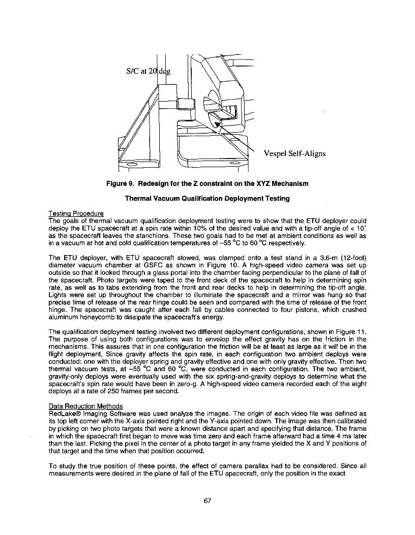
Figure 4. Initial Design of XYZ Hardpoint (right) and Cutaway View of XYZ Mechanism (left)
61

The ST5 aluminum pusher shown in Figure 3 contains a spring of type LHL-1000A-13 that imparts the 400-N spin up force. The spring’s compression is adjusted by a threaded rod. The tip of the pusher pushes against a stainless-steel-440C roller ball on the YZ Hardpoint on the spacecraft. Additional TufLite® bushings are located between the pusher and the aluminum pusher housing mounted on the YZ Mechanism stanchion. The spacecraft is fixed in the X, Y, and Z directions by the XYZ mechanism shown in Figure 4. A stainless steel shaft on the deployer fits into and is driven by a key in the aluminum XYZ hardpoint on the spacecraft. These two surfaces in metal to metal contact are impregnated with Polytetrafluoroethylene (PTFE) to reduce friction. TufLite® bushings in the XYZ hardpoint encircle the XYZ shaft. On the other end of this XYZ shaft there is a butterfly key. There is a spring of type LC-080-8 compressed inside the XYZ housing. When the XYZ shaft turns 20 deg, the butterfly key fits into the keyed slot and the XYZ shaft retracts out of the spacecraft. To provide restraint in the Z direction, a 410-stainless-steel cone reacts against an aluminum-7075 cup on the XYZ hardpoint. A similar XY-only mechanism, on the opposite side of the spacecraft acts coaxially and completes the hinge line. There is no Z-direction restraint needed. There are several stages required for the deployer design to spin up the spacecraft and deploy it from the LV. First, a LV separation pulse causes the Pinpuller to pull the pin from the clevis in the YZ mechanism, which releases the YZ hardpoint clevis. The spacecraft is then driven by the pusher to rotate about the XY and XYZ hardpoints. The key in each of these two hardpoints forces the two shafts to spin with the spacecraft. At about 7-deg, the pusher completes its throw and the spacecraft has reached its final rotational velocity. The spacecraft, now no longer in contact with the pusher, continues to rotate about the coaxial XY and XYZ shafts until it reaches a 20-deg angle. Finally, the two driven XY and XYZ shafts retract out of the slots in the XY and XYZ mechanisms. The spacecraft is then unrestrained and spins with a rate of 3.35 rad/s (32.4 rpm) about the Z-axis. Its translational speed is ~.72 m/s (28 in/s) at an angle of 20 deg from the interface plane normal.
Low Shock Pinpuller
The TiNi Aerospace Model P50-1310-4RS Pinpuller was selected for its flight-demonstrated reliability, compatibility with existing LV separation pulses, and low shock imparted to the surrounding structure. Its ball-lock detent mechanism is initiated by a Nitinol shape-memory-alloy wire trigger [2]. It fires with a margin of 1.5 under the 400-N (90-lbf) shear load imparted by the ST5 pusher. The Pinpuller pin is coated with Braycote lubricant to minimize friction as it retracts. Extensive subassembly-level testing at operational temperatures and worst-case electrical parameters verified this margin. The Pinpuller originally came with a 222-N (50-lbf) nominal retraction force. Assuming a friction coefficient of 0.4 and a 445-N (100-lbf) shear load led to a low analytical margin of 0.2 for release of the spacecraft. This was unacceptable for a mission critical element. The spring was upgraded to music wire, which gave a retraction force of 310 N (70 lbf). The mission spin rate requirement was also relaxed to lower the required pusher force to 400 N (90 lbf).
Pinpuller Testing Subassembly testing was conducted on the YZ mechanism to verify that the Pinpuller could operate with a margin of 1.5 above the flight pusher shear load of 400 N (90 lbf). To do this, an Instron® Universal Test Machine was used to apply the normal shear load on the pin in a temperature-controlled test cell. The Pinpuller was tested under the goal 1000 N (225 lbf) load at five temperatures: cold survival at -35 oC, cold qualification at -20 oC, ambient +20 oC, hot qualification at +50 oC, and hot survival at +60 oC. Discussions with LV providers introduced the possibility that the current to the Pinpuller might be limited to 5 A, as opposed to the initially planned 7.5-A limit. Because of this possibility, the Pinpuller was also tested at the 5-A current levels at all five temperatures. In total, there were 44 test conducted with the Pinpuller under a 1000-N (225-lbf) shear load: six trials for each current case at ambient temperature and four trials for each current case at the four temperatures.
62

Prior to every test, low-vapor-pressure lubricant Braycote 601 was applied to the pin. Prior to each hot or cold test, the test fixture was held for one hour at a soak temperature of 70 oC or -70 oC, respectively, to simulate the possibility that the spacecraft would be at a more extreme environment before moderating to one of the allowable temperatures for deployment. During each test, the Pinpuller was fired with a custom circuit that limited pulse voltage, current, and duration to prevent damage to the shape-memory-alloy wire inside the Pinpuller. After each test, the chamber had to be brought back to ambient temperature in order to reset the Pinpuller. A typical actuation time versus temperature profile for the Pinpuller at the two current levels appears in Figure 5. In all 44 tests at the various temperature and current levels, the Pinpuller fully retracted under goal shear loading of 1000 N (225 lbf). This demonstrated a Pinpuller release margin of 1.5.
0.0
10.0
20.0
30.0
40.0
50.0
60.0
70.0
80.0
90.0
-40 -20 0 20 40 60 80
Temperature (C)
Act
uatio
n Ti
me
(mse
c)
6.8 - 7.4 Amp Draw4.6 - 5.0 Amp Draw
Figure 5. Actuation Time Versus Temperature for Two Pinpuller Testing Current Cases
Structural Analysis
The ST5 deployer was structurally analyzed using a NASTRAN finite element analysis (FEA) model to predict its natural frequencies and structural response to the worst case LV loads [3]. The minimum predicted natural frequency for the final deployer design was 51.1 Hz, which exceeds the minimum natural frequency requirement of 35 Hz. A thorough stress analysis of the deployer structure was also conducted using classical analytical techniques. The results appear in Table 1. The minimum fastener margin of safety was +0.52 including 50% preload and occurred in the XYZ mechanism. The minimum component margin of safety was +0.55 and occurred in the bushings in the XYZ and XY mechanism. Based on this analysis, the deployer structure was deemed in compliance with the requirements set out in the ST5 Mechanical System Specification document [4].
63
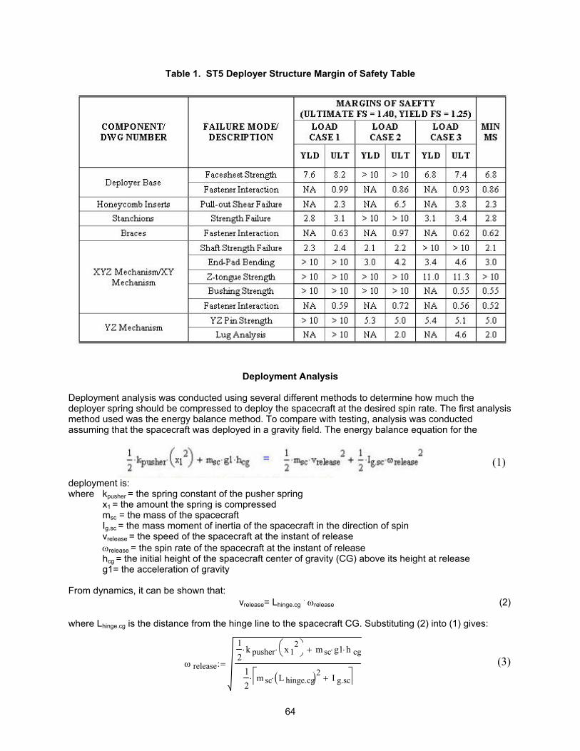
Table 1. ST5 Deployer Structure Margin of Safety Table
Deployment Analysis
Deployment analysis was conducted using several different methods to determine how much the deployer spring should be compressed to deploy the spacecraft at the desired spin rate. The first analysis method used was the energy balance method. To compare with testing, analysis was conducted assuming that the spacecraft was deployed in a gravity field. The energy balance equation for the
deployment is:
(1)
where kpusher = the spring constant of the pusher spring x1 = the amount the spring is compressed msc = the mass of the spacecraft
Ig.sc = the mass moment of inertia of the spacecraft in the direction of spin vrelease = the speed of the spacecraft at the instant of release ωrelease = the spin rate of the spacecraft at the instant of release
hcg = the initial height of the spacecraft center of gravity (CG) above its height at release g1= the acceleration of gravity
From dynamics, it can be shown that:
vrelease= Lhinge.cg . ωrelease (2) where Lhinge.cg is the distance from the hinge line to the spacecraft CG. Substituting (2) into (1) gives:
ω release
12
k pusher⋅ x12
⋅ m sc g1⋅ h cg⋅+
12
m sc L hinge.cg( )2⋅ I g.sc+
⋅
:=
(3)
64
By solving (3), the theoretical spin rate for the spacecraft can be determined. This equation can also easily be solved for x1 to determine how far the spring should be compressed to produce a certain spin rate. In addition to energy methods, a Newton force balance approach was used to determine a differential equation for the angular acceleration. Numerically solving this equation and then integrating to find angular velocity gave a release spin rate that was within 0.5% of the energy balance result.
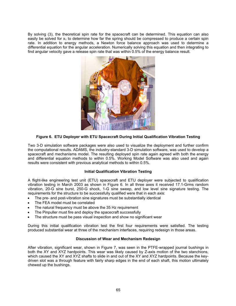
Figure 6. ETU Deployer with ETU Spacecraft During Initial Qualification Vibration Testing
Two 3-D simulation software packages were also used to visualize the deployment and further confirm the computational results. ADAMS, the industry-standard 3-D simulation software, was used to develop a spacecraft and mechanisms model. The resulting deployed spin rate again agreed with both the energy and differential equation methods to within 0.5%. Working Model Software was also used and again results were consistent with previous analytical methods to within 0.5%.
Initial Qualification Vibration Testing
A flight-like engineering test unit (ETU) spacecraft and ETU deployer were subjected to qualification vibration testing in March 2003 as shown in Figure 6. In all three axes it received 17.1-Grms random vibration, 20-G sine burst, 250-G shock, 1-G sine sweep, and low level sine signature testing. The requirements for the structure to be successfully qualified were that in each axis: • The pre- and post-vibration sine signatures must be substantially identical • The FEA model must be correlated • The natural frequency must be above the 35 Hz requirement • The Pinpuller must fire and deploy the spacecraft successfully • The structure must be pass visual inspection and show no significant wear During this initial qualification vibration test the first four requirements were satisfied. The testing produced substantial wear at three of the mechanism interfaces, requiring redesign in those areas.
Discussion of Wear and Mechanism Redesign After vibration, significant wear, shown in Figure 7, was seen in the PTFE-wrapped journal bushings in both the XY and XYZ hardpoints. This wear was likely caused by Z-axis motion of the two stanchions, which caused the XY and XYZ shafts to slide in and out of the XY and XYZ hardpoints. Because the key-driven slot was a through feature with fairly sharp edges in the end of each shaft, this motion ultimately chewed up the bushings.
65

The shafts were redesigned to incorporate a pocket by closing off the ends, which allowed full material contact between shaft and bushing, especially in the Y-axis. The tang was shortened to fit in the shaft pocket with 0.013-cm (0.005-in) clearance on all sides to prevent load transfer through it. In addition, the Tuf-Lite bushing was replaced by custom-machined Vespel. A brace was added to the XY stanchion to reduce the Z translation of the shafts. Significant wear also occurred at end of the aluminum pusher. There was major dimpling of the pusher, shown in Figure 8, where it met the stainless steel roller ball on the deployer. The pusher was redesigned by cutting it back 0.508 cm (0.2 in) and installing a 17-7-stainless-steel tip to contact the roller ball. Finally, there was significant wear on the cup and cone interface of the XYZ mechanism. Brinelling occurred where the stainless-steel-410 cone rubbed on the aluminum-7075 cup and was likely due to the previously discussed Z translation of the spacecraft. This interface was redesigned as an aluminum-7075 tongue in a Vespel bushing as shown in Figure 9. The Vespel slot aligns itself in the housing and contains a diagonal cut-back that assures that the tongue is clear of the Vespel slot when the spacecraft has deployed 6 deg, before the pusher stroke ends at 7.25 deg. The deployer was analyzed structurally again. All of these design changes had positive margins despite using conservative assumptions. It was also shown by test (see next section) that none of these changes would affect the deployment of the spacecraft.
Figure 7. Wear of XY and XYZ Journal Bushings (right) and Tang in Pocket Redesign (left)
Wear
Figure 8. Brinelling of the Cup on the XYZ Hardpoint (left) and Dimpling of Pusher (right)
66

where xapparent and yapparent are the apparent positions in inches, xactual and yactual are the actual positions in the spacecraft’s plane of the fall, and 81 is the distance in inches from camera to the plane of fall. To determine the spin rate for each deploy, two photo targets were chosen on the spacecraft such that each was visible during the entire fall of the spacecraft. The positions of these two targets were found at 8 ms intervals beginning just after the XY and XYZ mechanisms released the spacecraft until just before it was caught by the cables roughly 200 ms later. The two target positions gave an angle of the spacecraft at every time. Then the spin rate could be found by taking the change in this angle divided by the elapsed time between the frames where the spacecraft angles occurred. 26 angles for each deploy determined the average spin rate of the spacecraft. To determine the zero-g spin rate for each deploy, the average spin rates from the six spring-and-gravity deploys were compared to the average spin rates from the two gravity-only trials. From equation (3), it can be shown that the gravity-only spin rate squared equals the spring-and-gravity spin rate squared minus the gravity-only spin rate squared. Spin Rate Results The primary goal for the qualification deployment testing was to show that the measured spin rate in zero-g was within 10% of the desired value. While the spin rate values were fairly consistent for all temperatures and flip types, the data showed that the six zero-gravity spin rates were an average of 13% less than the 3.4 rad/s (32.4 rpm) spin rate predicted by the analytical models. To explain this discrepancy, the possible error sources were lumped into five categories: 1) Deployment stand flexibility (Stand recoiled on deploy)
2) Modeling error (Imperfect values for x1, msc, Ig.sc, Lhing.cg and hcg) 3) Friction and losses due to non-flight interfaces (Catching cables) 4) Measurement error (Imperfect pixel picking) 5) Friction and losses due to flight interfaces (Pusher and XY and XYZ mechanisms) These possible error sources were then examined and quantified to determine how much each contributed to the 13% difference between the measurement and the model, keeping in mind that the first four were caused by imperfect techniques and that the first and fifth would likely be present on flight. The first error source, energy loss due to stand recoil, was a major contributor to the discrepancy. From the video files, it was determined that the stand deflected roughly 3.0 mm (0.12 in) as the spacecraft deployed. A separate test to revealed that a 356 N (80 lbf) tug on the stand caused a 2.0 mm (0.08 in) deflection, which meant that the stand had a lateral stiffness of roughly 175 N/mm (1000 lbf/in). The
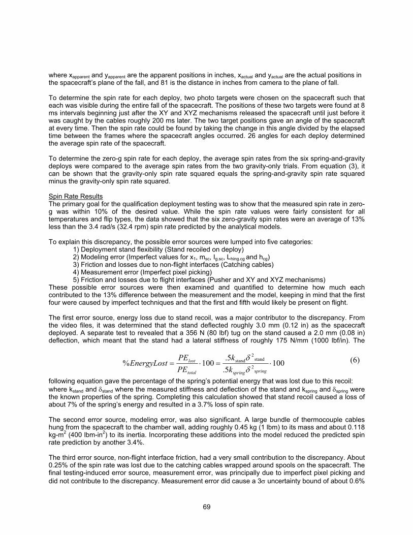
following equation gave the percentage of the spring’s potential energy that was lost due to this recoil:
1005.5.
100%s
2s
stand2
stand ⋅=⋅=pringpringtotal
lost
kk
PEPEEnergyLost
δδ (6)
where kstand and δstand where the measured stiffness and deflection of the stand and kspring and δspring were the known properties of the spring. Completing this calculation showed that stand recoil caused a loss of about 7% of the spring’s energy and resulted in a 3.7% loss of spin rate. The second error source, modeling error, was also significant. A large bundle of thermocouple cables hung from the spacecraft to the chamber wall, adding roughly 0.45 kg (1 lbm) to its mass and about 0.118 kg-m2 (400 lbm-in2) to its inertia. Incorporating these additions into the model reduced the predicted spin rate prediction by another 3.4%. The third error source, non-flight interface friction, had a very small contribution to the discrepancy. About 0.25% of the spin rate was lost due to the catching cables wrapped around spools on the spacecraft. The final testing-induced error source, measurement error, was principally due to imperfect pixel picking and did not contribute to the discrepancy. Measurement error did cause a 3σ uncertainty bound of about 0.6%
69
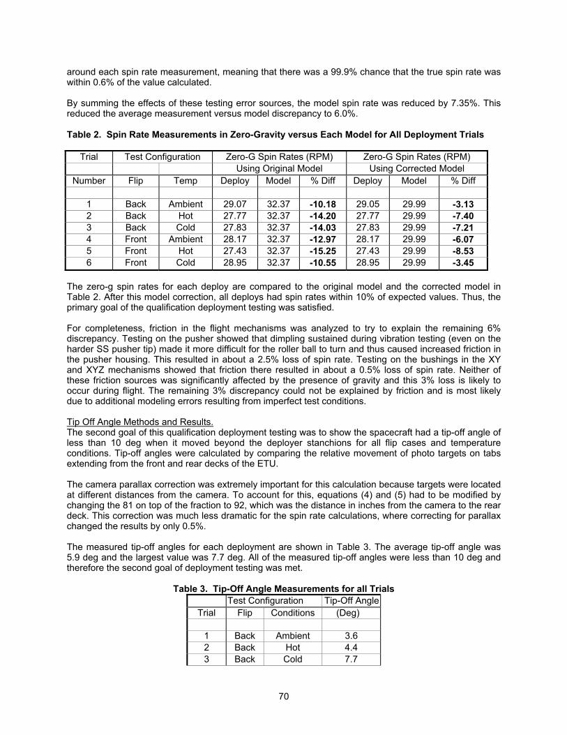
around each spin rate measurement, meaning that there was a 99.9% chance that the true spin rate was within 0.6% of the value calculated. By summing the effects of these testing error sources, the model spin rate was reduced by 7.35%. This reduced the average measurement versus model discrepancy to 6.0%. Table 2. Spin Rate Measurements in Zero-Gravity versus Each Model for All Deployment Trials
Trial Test Configuration Zero-G Spin Rates (RPM) Zero-G Spin Rates (RPM) Using Original Model Using Corrected Model
Number Flip Temp Deploy Model % Diff Deploy Model % Diff
1 Back Ambient 29.07 32.37 -10.18 29.05 29.99 -3.13 2 Back Hot 27.77 32.37 -14.20 27.77 29.99 -7.40 3 Back Cold 27.83 32.37 -14.03 27.83 29.99 -7.21 4 Front Ambient 28.17 32.37 -12.97 28.17 29.99 -6.07 5 Front Hot 27.43 32.37 -15.25 27.43 29.99 -8.53 6 Front Cold 28.95 32.37 -10.55 28.95 29.99 -3.45
The zero-g spin rates for each deploy are compared to the original model and the corrected model in Table 2. After this model correction, all deploys had spin rates within 10% of expected values. Thus, the primary goal of the qualification deployment testing was satisfied. For completeness, friction in the flight mechanisms was analyzed to try to explain the remaining 6% discrepancy. Testing on the pusher showed that dimpling sustained during vibration testing (even on the harder SS pusher tip) made it more difficult for the roller ball to turn and thus caused increased friction in the pusher housing. This resulted in about a 2.5% loss of spin rate. Testing on the bushings in the XY and XYZ mechanisms showed that friction there resulted in about a 0.5% loss of spin rate. Neither of these friction sources was significantly affected by the presence of gravity and this 3% loss is likely to occur during flight. The remaining 3% discrepancy could not be explained by friction and is most likely due to additional modeling errors resulting from imperfect test conditions. Tip Off Angle Methods and Results. The second goal of this qualification deployment testing was to show the spacecraft had a tip-off angle of less than 10 deg when it moved beyond the deployer stanchions for all flip cases and temperature conditions. Tip-off angles were calculated by comparing the relative movement of photo targets on tabs extending from the front and rear decks of the ETU. The camera parallax correction was extremely important for this calculation because targets were located at different distances from the camera. To account for this, equations (4) and (5) had to be modified by changing the 81 on top of the fraction to 92, which was the distance in inches from the camera to the rear deck. This correction was much less dramatic for the spin rate calculations, where correcting for parallax changed the results by only 0.5%. The measured tip-off angles for each deployment are shown in Table 3. The average tip-off angle was 5.9 deg and the largest value was 7.7 deg. All of the measured tip-off angles were less than 10 deg and therefore the second goal of deployment testing was met.
Table 3. Tip-Off Angle Measurements for all Trials
Test Configuration Tip-Off AngleTrial Flip Conditions (Deg)
1 Back Ambient 3.6 2 Back Hot 4.4 3 Back Cold 7.7
70

4 Front Ambient 6.6 5 Front Hot 6.9 6 Front Cold 6.2
Table 4. Natural Frequency Response Results Obtained During Requalification Vibration Testing
Axis Pre-Sweep Low Random High Random Post-Sweep Analysis (Hz) (Hz) (Hz) (Hz) (Hz)
X 49 44 50 49 55 Y 125 100 124 114 68 Z 41 42 50 41 52
Figure 12. Comparison of X Force Sum in X-Axis Vibration Pre (red) and Post (blue) Sine Signatures During the Requalification Vibration Test
Requalification Vibration Testing
The final step that remained to qualify the deployer was to show that the redesigned mechanisms would not wear during qualification vibration levels. Just as in the initial qualification vibration test, the ETU deployer and ETU spacecraft were subjected to 17.1-Grms random vibration, 20-G sine burst, 250-G shock, 1-G sine sweep, and low level sine signature testing in all three axes. After each axis of testing, the Pinpuller fired and the S/C was successfully deployed. In each axis, initial sine signature sweeps and those run post testing remained very similar to each other. These frequencies are shown in Table 4 and a representative frequency plot comparing pre- and post-signatures in the X-axis is shown in Figure 12. The ETU successfully withstood structural loads and demonstrated substantially identical pre- and post- sine signatures and its fundamental frequencies of 49 Hz in the X-axis, 114 Hz in the Y-axis, and 41 Hz in the Z-axis all exceeded the minimum frequency requirement of 35 Hz. After each axis of testing, the Pinpuller fired and the S/C was successfully deployed. It should be noted that due to clearances in the mechanisms, the response of the ETU spacecraft and deployer is very nonlinear. In all the three axes, the fundamental frequencies differed significantly between the high (full) level random and the low (-18 dB) level random runs. The requirement to correlate
71

the FEA Model was satisfied by adjusting the spring constants for each mechanism in each direction until the model matched the test results. The only vibration requirement left to satisfy was the post-vibration visual inspection. The aluminum tongue in Vespel slot interface of the XYZ mechanism was of particular concern. The Vespel slot was initially 0.645-mm (0.254-in) wide and remained 0.645-mm (0.254-in) wide after X-axis and Y-axis testing. After Z-axis testing the slot opened up only slightly to 0.650-mm (0.256-in) wide, which was within specification. Virtually no debris was collected in the tent placed around mechanism and no traces of Vespel were found by contamination inspection. The redesigns made to the other mechanisms also proved successfully and, aside from minor pusher tip dimpling, there was no significant wear detected in any of the interfaces. Thus, the ETU deployer and ETU spacecraft passed the post-vibration visual inspection requirement and successfully completed all of the requirements imposed on it for qualification for space flight use.
Lessons Learned
• Transducer-based rate sensors are not the only choice for velocity data. High-speed video gave direct spin rate information, though data had some pixel-picking error and parallax had to be accounted for. The photo technician and equipment rental cost about $10,000 for 2 weeks.
• All parts of a test setup that may lead to discrepancies from a theoretical model should be considered before testing. Correcting a model afterwards to match a test is not as convincing.
• Determining the on-orbit spin rate from ground data compounded errors. This would have been the case even with on board transducers. The most straightforward measurement would have required a Zero-Gravity research lab, with its own set of constraints and significantly higher cost.
• When a mechanism is going to face vibration, sharp edges should always be avoided to reduce the chances of gouging or chewing up hardware.
• Hard plastics, such as Vespel, could be used instead of metals if a mechanism shows wear. • In our drive for miniaturized components, we started with innocently low assumptions for margin
requirements and had to pay for it with extra testing. Instead of margins in the 1-2 range, 4 is recommended for initial design. When this extra margin is not achievable due to resource limitations on micro-satellites, component testing must make up the difference in confidence level.
Conclusions
The Frisbee spin up is a viable technique for imparting a mission-critical spin rate to a micro sat. Deck space is preserved, the design is simple, and rate precision has been demonstrated to better than ±10% with low tip-off. The spin rate was measured by high-speed video frame capture of the target locations on the deploying spacecraft. The design was demonstrated with development hardware and a flight-like engineering test unit qualified the design. Low design margin and heritage was compensated by more component-level testing in a “skunkworks” environment. In the move towards miniaturized spacecraft for constellation science missions, new ways of dealing with risk must be adopted. This single-string spacecraft mission afforded the opportunity to research strategies for mechanism development under a less risk-averse atmosphere. Reliable suppliers, adequate facilities, and experienced personnel made up the balance of the success formula.
References [1] “ST-5 Critical Design Review” Presentation1, Peter Rossoni June 2002 [2] Michael Bokaie and Kevin Barajas: “Non-Explosive Pinpuller and Rotary Actuators” 32nd Aerospace Mechanisms Symposium, NASA Kennedy Space Center, May13-15 1998 [3] SAI-ANYS-396 William McGill1, Swales Aerospace, 2003
1 ST-5 internal project document, subject to export control restrictions
72