Deployment Guide - Dell Force10 · 2008-10-07 · Layer 2-7 High Availability Deployment Guide ......
29
Layer 2-7 High Availability Deployment Guide A Technical Guide for Business Continuity Deployment Guide
Transcript of Deployment Guide - Dell Force10 · 2008-10-07 · Layer 2-7 High Availability Deployment Guide ......
Layer 2-7 High Availability Deployment GuideA Technical Guide for Business Continuity
Deployment Guide
Deployment Guide
Notice:
The information in this publication is subject to change without notice.
THIS PUBLICATION IS PROVIDED “AS IS” WITHOUT WARRANTIES OF ANY KIND, EXPRESS OR IMPLIED, INCLUDING ANY WARRANTIES OF MERCHANTABILITY, FITNESS FOR A PARTICULAR PURPOSE OR NONINFRINGEMENT. CITRIX SYSTEMS, INC. (“CITRIX”), SHALL NOT BE LIABLE FOR TECHNICAL OR EDITORIAL ERRORS OR OMISSIONS CONTAINED HEREIN, NOR FOR DIRECT, INCIDENTAL, CONSEQUENTIAL OR ANY OTHER DAMAGES RESULTING FROM THE FURNISHING, PERFORMANCE, OR USE OF THIS PUBLICATION, EVEN IF CITRIX HAS BEEN ADVISED OF THE POSSIBILITY OF SUCH DAMAGES IN ADVANCE.
This publication contains information protected by copyright. Except for internal distribution, no part of this publication may be photocopied or reproduced in any form without prior written consent from Citrix.
The exclusive warranty for Citrix products, if any, is stated in the product documentation accompanying such products. Citrix does not warrant products other than its own.
Product names mentioned herein may be trademarks and/or registered trademarks of their respective companies.
Copyright © 2008 Citrix Systems, Inc., 851 West Cypress Creek Road, Ft. Lauderdale, Florida 33309-2009 U.S.A. All rights reserved.

Table of ContentsIntroduction ..........................................................................................................................................4Prerequisites .........................................................................................................................................5Network Diagram .................................................................................................................................6NetScaler Configuration ........................................................................................................................8
Deployment Model: NetScaler High Availability, Two-Arm Mode .......................................................8Important Considerations for NetScaler High Availability ...................................................................9High Availability Command Synchronization ...................................................................................12Important NetScaler IP Addresses .................................................................................................13Add a Default Route ......................................................................................................................13IP Addresses, Interfaces and VLANs ..............................................................................................14Configuring the Virtual MAC ...........................................................................................................15High Availability Failover Operation .................................................................................................16Before HA Failover .........................................................................................................................17After HA Failover ............................................................................................................................18
Appendix A - NetScaler Application Switch Configuration ...................................................................20Appendix B - Layer 2/3 Switch/Router Configuration ..........................................................................23Appendix C - Helpful NetScaler CLI Commands .................................................................................28
4
IntroductionCitrix® NetScaler® optimizes the delivery of web applications— increasing security and improving performance and Web server capacity. This approach ensures the best total cost of ownership (TCO), security, availability, and performance for Web applications. The Citrix NetScaler solution is a comprehensive network system that combines high-speed load balancing and content switching with state-of-the-art application acceleration, Layer 4-7 traffic management, data compression, dynamic content caching, SSL acceleration, network optimization, and robust application security into a single, tightly integrated solution. Deployed in front of application servers, the system significantly reduces processing overhead on application and database servers, reducing hardware and bandwidth costs.
To help ensure application availability, NetScaler delivers fine-grained direction of client requests to ensure optimal distribution of traffic. In addition to Layer 4 information (protocol and port number), traffic management policies for TCP applications can be based upon any application-layer content. Administrators can granularly segment application traffic based upon information contained within an HTTP request body or TCP payload, as well as L4-7 header information such as URL, application data type or cookie. Numerous load-balancing algorithms and extensive server health checks provide greater application availability by ensuring client requests are directed only to correctly behaving servers.
With the confidence that Citrix will keep your Applications online and servicing your clients, you may want to be assured that your Layer 2-3 Infrastructure is built for Business Continuity as well. Many pioneering advancements have been made in Layer 2-3 switching/routing in both software and hardware features for redundancy and high availability. Force10 Networks makes full use of these advancements in their product set for both Enterprise and Service Provider class switch/routers. With VLAN features standardized by IEEE in 802.1q specifications and Layer 3 routing protocols collapsed into switching platforms, organizations can take full advantage of the consolidation paradigm.
As enterprises and service providers move toward the path of consolidation, they will continue to look for ways to guarantee Business Continuity for their customer base at higher layers on the OSI stack. Citrix NetScaler provides this through a High Availability pair, and is easy to configure through the NetScaler GUI.
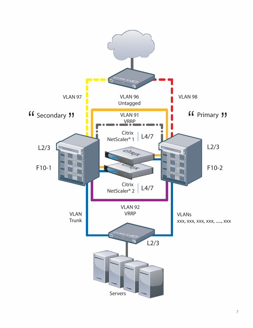
The Citrix NetScaler serves as the Layer 4-7 switch accepting incoming traffic from an untagged VLAN from the external network, and switching it back to the appropriate server farm on the backend. The Layer 2-3 switch/routers, running VRRP, serve as conduits for 802.1q VLANs, Trunks, VRRP Protocol, and Inter-VLAN routing using industry standard OSPF.
Combining software and hardware redundant features at Layer 2-3 with Citrix NetScaler Layer 4-7 High Availability ensures that all the network layers are covered in your datacenter to ensure uptime and business continuity, while you consolidate resources to do more with less. This deployment guide walks through the configuration details of how to configure the Citrix NetScaler and Layer 2-3 switch/router to provide this type of integration and high availability.

5
PrerequisitesCitrix NetScaler L4/7 Application Switch, running version 8.0+, Quantity x 2 for HA deployment.
Force10 L2/3 switch/routers, w/support for 802.1q Tagging & Trunking, VRRP, OSPF. Quantity x 4
Client laptop/workstation running Internet Explorer 6.0+.
•
•
•
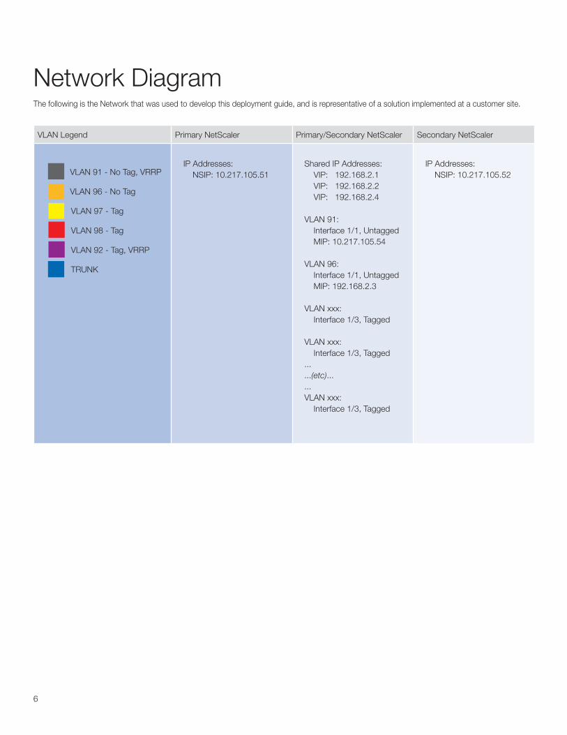
VLAN Legend Primary NetScaler Primary/Secondary NetScaler Secondary NetScaler
VLAN 91 - No Tag, VRRP
VLAN 96 - No Tag
VLAN 97 - Tag
VLAN 98 - Tag
VLAN 92 - Tag, VRRP
TRUNK
IP Addresses: NSIP: 10.217.105.51
Shared IP Addresses: VIP: 192.168.2.1 VIP: 192.168.2.2 VIP: 192.168.2.4
VLAN 91: Interface 1/1, Untagged MIP: 10.217.105.54
VLAN 96: Interface 1/1, Untagged MIP: 192.168.2.3
VLAN xxx: Interface 1/3, Tagged
VLAN xxx: Interface 1/3, Tagged......(etc)......VLAN xxx: Interface 1/3, Tagged
IP Addresses: NSIP: 10.217.105.52
6
The following is the Network that was used to develop this deployment guide, and is representative of a solution implemented at a customer site.
Network Diagram
7
VLAN 96Untagged
Servers
L2/3
L2/3
PrimarySecondary
L2/3
F10-2F10-1
VLAN 97
Citrix NetScaler® 2 L4/7
Citrix NetScaler® 1 L4/7
VLAN 92VRRPVLAN
TrunkVLANsxxx, xxx, xxx, xxx, ....., xxx
VLAN 91VRRP
VLAN 98
E600E600
S50N
S50N
8
NetScaler ConfigurationDeployment Model: NetScaler High Availability, Two-Arm Mode
The NetScalers in this example will be deployed as a high availability pair, in two-arm mode. Always start with the first NetScaler. The NetScalers in Two-Arm mode provide the utmost is site security, as they provide a full reverse-proxy gateway to intercept incoming traffic before it is sent to the Application servers on the backend. As the intelligence moves up the stack, the NetScaler provides the Layer 4-7 switching intelligence needed to performance Application Layer switching, caching, compression, load balancing, acceleration and security.
There are two main components that require installation in this environment, the Citrix NetScaler(s), and the Layer 2/3 switch/routers with VLAN trunking and tagging. We will start with the NetScaler configuration, step-by-step.
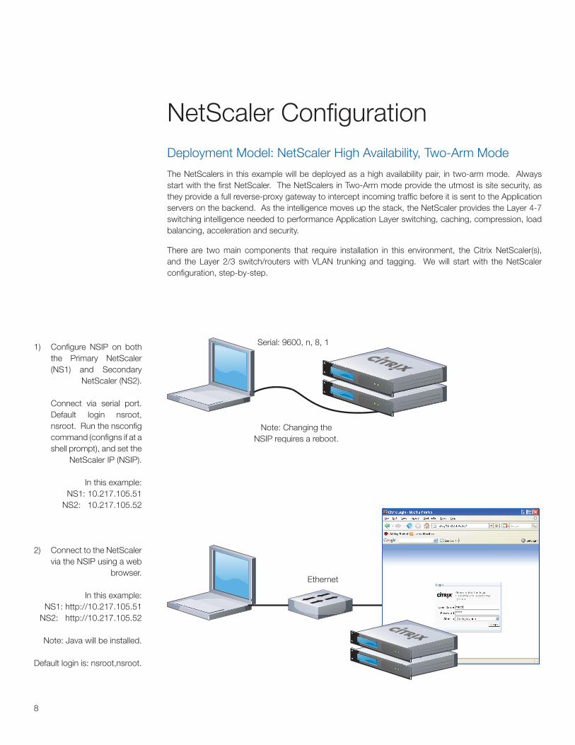
1) Configure NSIP on both the Primary NetScaler (NS1) and Secondary
NetScaler (NS2).
Connect via serial port. Default login nsroot, nsroot. Run the nsconfig command (configns if at a shell prompt), and set the
NetScaler IP (NSIP).
In this example: NS1: 10.217.105.51
NS2: 10.217.105.52
Serial: 9600, n, 8, 1
2) Connect to the NetScaler via the NSIP using a web
browser.
In this example: NS1: http://10.217.105.51
NS2: http://10.217.105.52
Note: Java will be installed.
Default login is: nsroot,nsroot.
Ethernet
Note: Changing the NSIP requires a reboot.
9
If you have two Application Switches, you can deploy them in a configuration where one Application Switch actively accepts connections and manages servers, while the second monitors the first. If the first Application Switch quits accepting connections for any reason, the second Application Switch takes over and begins actively accepting connections. This prevents downtime and ensures that the services provided by the Application Switch will remain available even if one Application Switch ceases to function.
Important Considerations for NetScaler High AvailabilityThe passwords for both NetScalers ‘nsroot’ account must match. You must change these manually on the switches, they are not synchronized.
The maximum node ID for Application Switches in an HA pair is 64.
Both NetScaler HA peers must be running the same version of code.
The configuration files in ‘ns.conf’ must match on both NetScalers. For this to happen, the following must occur:
The primary and secondary NetScaler Application switches must be configured with their own unique NSIP’s.
The ‘node id’ and ‘IP Address’ of one Application switch must point to the other Application switch (it’s HA peer).
You must configure RPC node passwords onto both Applicaiton switches. Initially, all Application Switches are configured with the same RPC node password. To enhance security, you should change these default RPC node passwords.
•
•
•
•
»
»
»
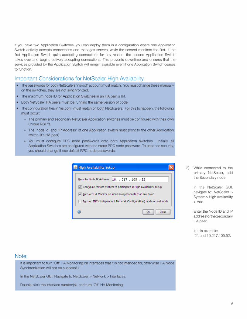
3) While connected to the primary NetScaler, add the Secondary node.
In the NetScaler GUI, navigate to: NetScaler > System > High Availability > Add.
Enter the Node ID and IP address for the Secondary HA peer.
In this example: ‘2’, and 10.217.105.52.
Note:It is important to turn ‘Off’ HA Monitoring on interfaces that it is not intended for, otherwise HA Node Synchronization will not be successful.
In the NetScaler GUI: Navigate to NetScaler > Network > Interfaces.
Double-click the interface number(s), and turn ‘Off’ HA Monitoring.
10
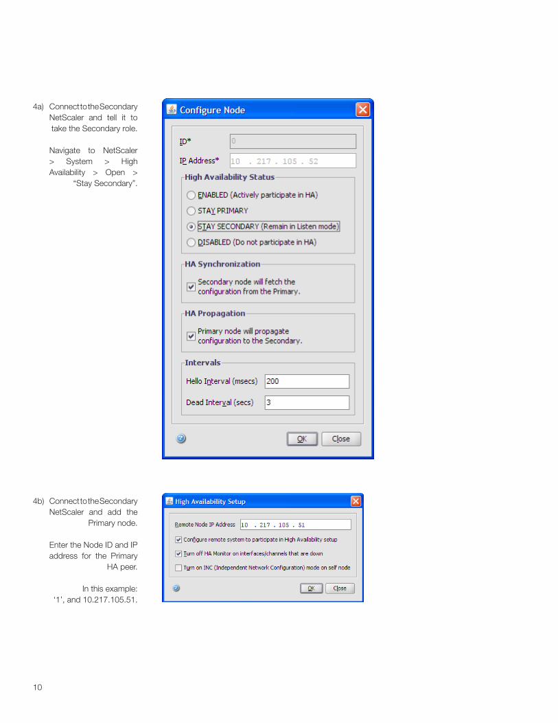
4a) Connect to the Secondary NetScaler and tell it to take the Secondary role.
Navigate to NetScaler > System > High Availability > Open >
“Stay Secondary”.
4b) Connect to the Secondary NetScaler and add the
Primary node.
Enter the Node ID and IP address for the Primary
HA peer.
In this example: ‘1’, and 10.217.105.51.
11
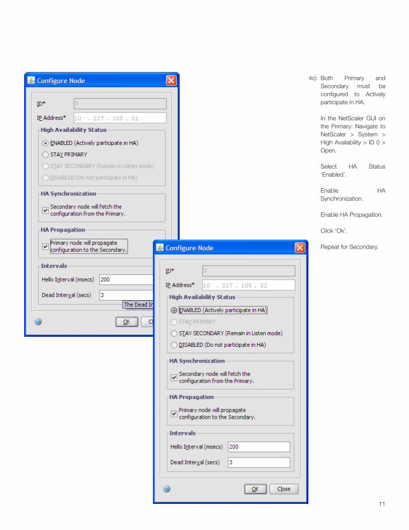
4c) Both Primary and Secondary must be configured to Actively participate in HA.
In the NetScaler GUI on the Primary: Navigate to NetScaler > System > High Availability > ID 0 > Open.
Select HA Status ‘Enabled’.
Enable HA Synchronization.
Enable HA Propagation.
Click ‘Ok’.
Repeat for Secondary.
12
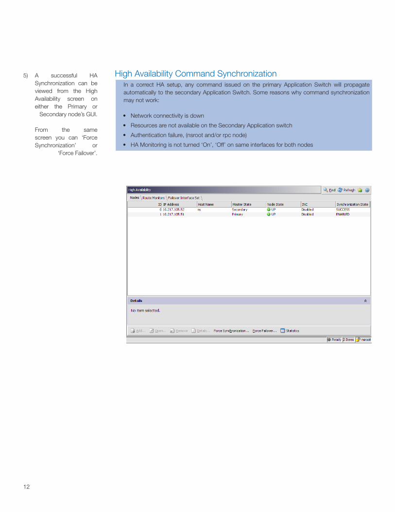
5) A successful HA Synchronization can be viewed from the High Availability screen on either the Primary or
Secondary node’s GUI.
From the same screen you can ‘Force Synchronization’ or
‘Force Failover’.
High Availability Command SynchronizationIn a correct HA setup, any command issued on the primary Application Switch will propagate automatically to the secondary Application Switch. Some reasons why command synchronization may not work:
Network connectivity is down
Resources are not available on the Secondary Application switch
Authentication failure, (nsroot and/or rpc node)
HA Monitoring is not turned ‘On’, ‘Off’ on same interfaces for both nodes
•
•
•
•
1313
Important NetScaler IP AddressesAcronym Description Usage
Note: NSIP is Mandatory and requires a reboot.
NSIP NetScaler IP Address The NetScaler IP (NSIP) is the management IP address for the appliance, and is used for all management related access to the appliance. There can only be one NSIP.
MIP Mapped IP Address The mapped IP address (MIP) is used by the Application Switch to represent the client when communicating with the backend managed server. Mapped IP addresses (MIP) are used for server-side connections and Reverse NAT. Think of this as the client’s source address on the server-side of the Application Switch, assuming a two-arm proxy deployment. In this example you can think of it as the Tagged VLAN IP.
SNIP Subnet IP Address The Subnet IP address (SNIP) allows the user to access an Application Switch from an external host that is residing on another subnet. When a subnet IP address is added, a corresponding route entry is made in the route table. Only one such entry is made per subnet. The route entry corresponds to the first IP address added in the subnet.
VIP Virtual IP Address The Virtual Server IP address (VIP) is used by the Application Switch to represent the public facing ip address of the managed services. ARP and ICMP attributes on this IP address allow users to host the same vserver on multiple Application Switches residing on the same broadcast domain.
DFG Default Gateway IP Address of the router that forwards traffic outside of the subnet where the appliance is installed.
TIP: Disabling the blinking LCD PanelThe LCD panel on the front of the NetScaler will flash intermittently until the unused interfaces are disabled and HA monitoring is turned off on them. In the GUI, Navigate to NetScaler > Network > Interfaces. Select an interface, right-click to disable. Right-click to Open, and disable HA monitoring.
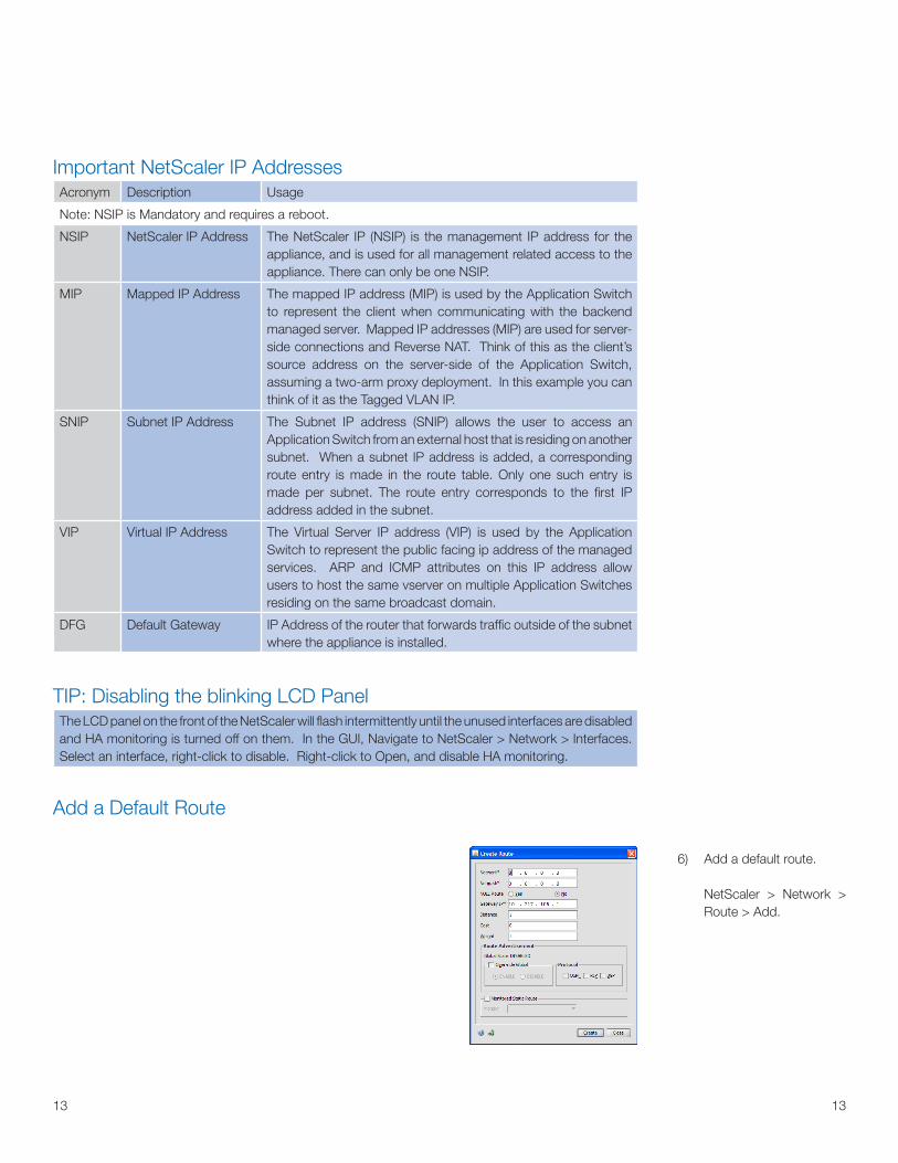
Add a Default Route
6) Add a default route.
NetScaler > Network > Route > Add.
14
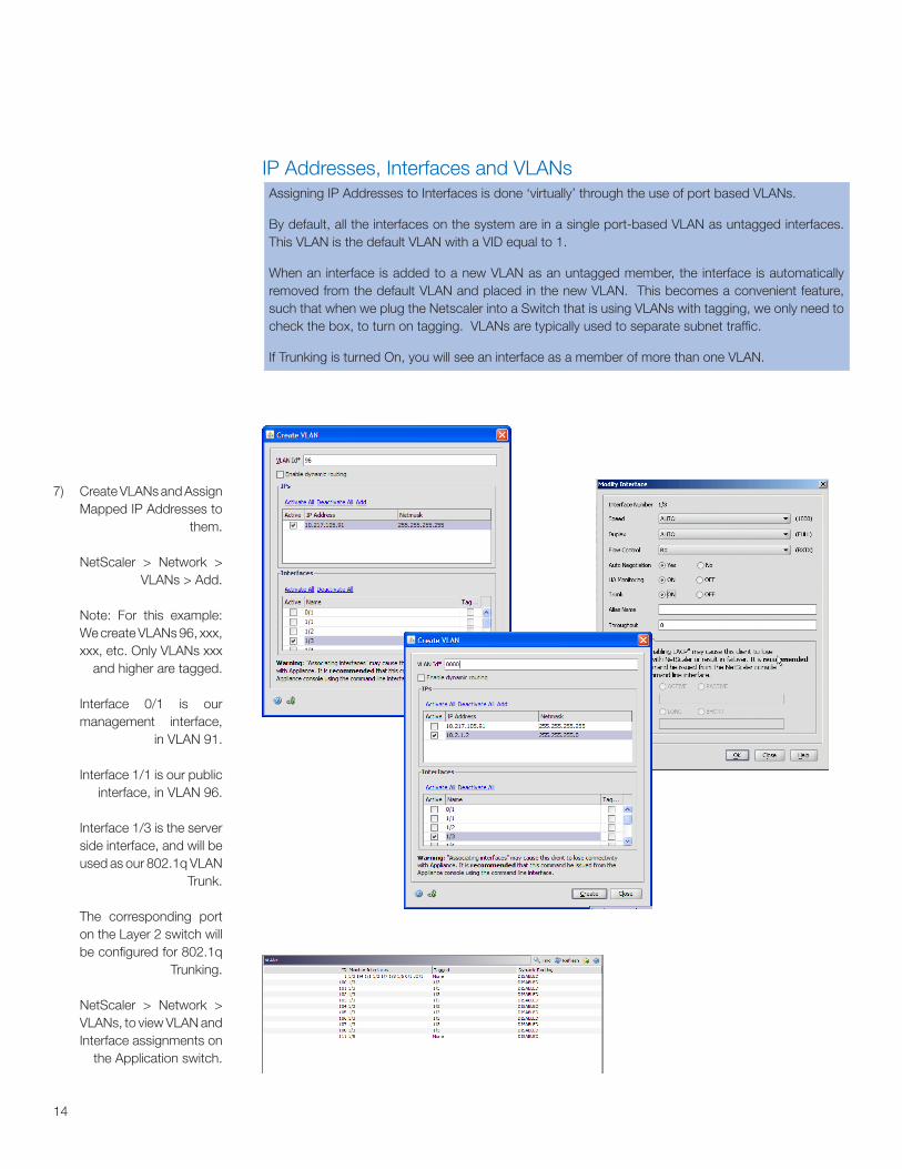
7) Create VLANs and Assign Mapped IP Addresses to
them.
NetScaler > Network > VLANs > Add.
Note: For this example: We create VLANs 96, xxx, xxx, etc. Only VLANs xxx
and higher are tagged.
Interface 0/1 is our management interface,
in VLAN 91.
Interface 1/1 is our public interface, in VLAN 96.
Interface 1/3 is the server side interface, and will be used as our 802.1q VLAN
Trunk.
The corresponding port on the Layer 2 switch will be configured for 802.1q
Trunking.
NetScaler > Network > VLANs, to view VLAN and Interface assignments on
the Application switch.
IP Addresses, Interfaces and VLANsAssigning IP Addresses to Interfaces is done ‘virtually’ through the use of port based VLANs.
By default, all the interfaces on the system are in a single port-based VLAN as untagged interfaces. This VLAN is the default VLAN with a VID equal to 1.
When an interface is added to a new VLAN as an untagged member, the interface is automatically removed from the default VLAN and placed in the new VLAN. This becomes a convenient feature, such that when we plug the Netscaler into a Switch that is using VLANs with tagging, we only need to check the box, to turn on tagging. VLANs are typically used to separate subnet traffic.
If Trunking is turned On, you will see an interface as a member of more than one VLAN.
15
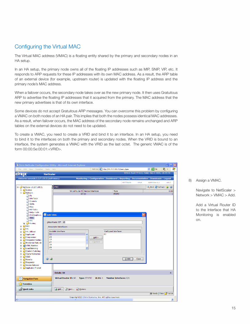
8) Assign a VMAC.
Navigate to NetScaler > Network > VMAC > Add.
Add a Virtual Router ID to the Interface that HA Monitoring is enabled on.
Configuring the Virtual MAC
The Virtual MAC address (VMAC) is a floating entity shared by the primary and secondary nodes in an HA setup.
In an HA setup, the primary node owns all of the floating IP addresses such as MIP, SNIP, VIP, etc. It responds to ARP requests for these IP addresses with its own MAC address. As a result, the ARP table of an external device (for example, upstream router) is updated with the floating IP address and the primary node’s MAC address.
When a failover occurs, the secondary node takes over as the new primary node. It then uses Gratuitous ARP to advertise the floating IP addresses that it acquired from the primary. The MAC address that the new primary advertises is that of its own interface.
Some devices do not accept Gratuitous ARP messages. You can overcome this problem by configuring a VMAC on both nodes of an HA pair. This implies that both the nodes possess identical MAC addresses. As a result, when failover occurs, the MAC address of the secondary node remains unchanged and ARP tables on the external devices do not need to be updated.
To create a VMAC, you need to create a VRID and bind it to an interface. In an HA setup, you need to bind it to the interfaces on both the primary and secondary nodes. When the VRID is bound to an interface, the system generates a VMAC with the VRID as the last octet. The generic VMAC is of the form 00:00:5e:00:01:<VRID>.
16
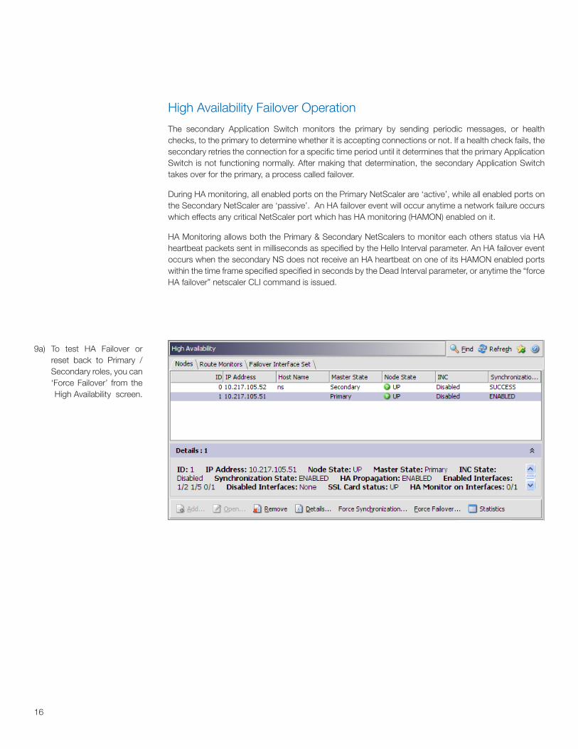
High Availability Failover Operation
The secondary Application Switch monitors the primary by sending periodic messages, or health checks, to the primary to determine whether it is accepting connections or not. If a health check fails, the secondary retries the connection for a specific time period until it determines that the primary Application Switch is not functioning normally. After making that determination, the secondary Application Switch takes over for the primary, a process called failover.
During HA monitoring, all enabled ports on the Primary NetScaler are ‘active’, while all enabled ports on the Secondary NetScaler are ‘passive’. An HA failover event will occur anytime a network failure occurs which effects any critical NetScaler port which has HA monitoring (HAMON) enabled on it.
HA Monitoring allows both the Primary & Secondary NetScalers to monitor each others status via HA heartbeat packets sent in milliseconds as specified by the Hello Interval parameter. An HA failover event occurs when the secondary NS does not receive an HA heartbeat on one of its HAMON enabled ports within the time frame specified specified in seconds by the Dead Interval parameter, or anytime the “force HA failover” netscaler CLI command is issued.
9a) To test HA Failover or reset back to Primary /Secondary roles, you can ‘Force Failover’ from the High Availability screen.
17
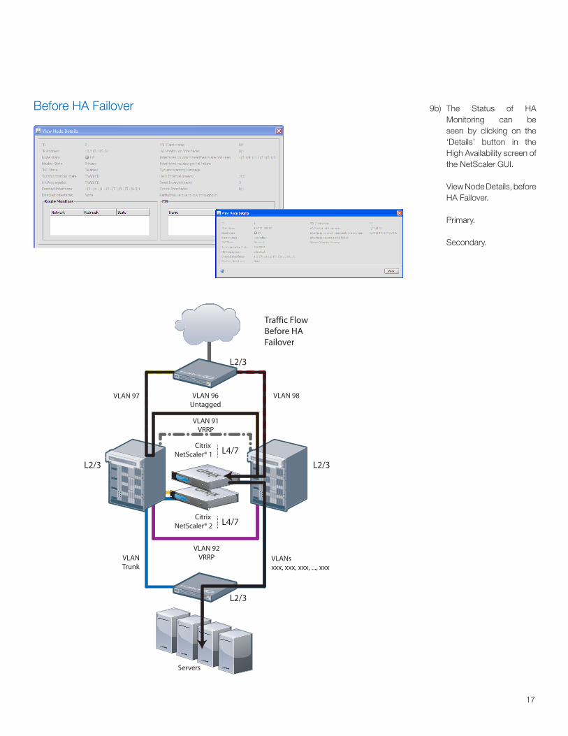
9b) The Status of HA Monitoring can be seen by clicking on the ‘Details’ button in the High Availability screen of the NetScaler GUI.
View Node Details, before HA Failover.
Primary.
Secondary.
Before HA Failover
VLAN 96Untagged
Servers
L2/3
L2/3
L2/3
L2/3
VLAN 97
Citrix NetScaler® 2 L4/7
Citrix NetScaler® 1 L4/7
VLAN 92VRRPVLAN
TrunkVLANsxxx, xxx, xxx, ..., xxx
VLAN 91VRRP
VLAN 98
E600E600
S50N
S50N
Traffic Flow Before HA Failover
18
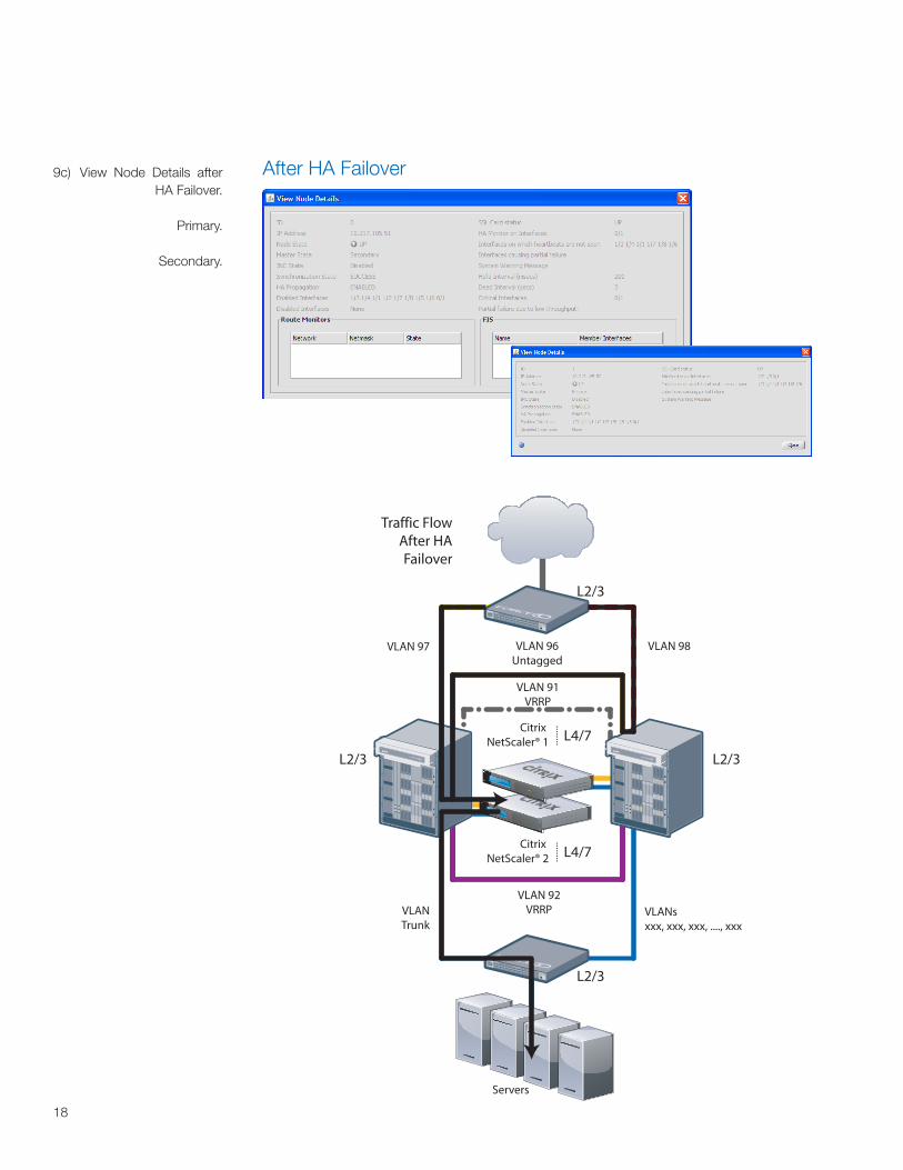
9c) View Node Details after HA Failover.
Primary.
Secondary.
After HA Failover
VLAN 96Untagged
Servers
L2/3
L2/3
L2/3
L2/3
VLAN 97
Citrix NetScaler® 2 L4/7
Citrix NetScaler® 1 L4/7
VLAN 92VRRPVLAN
TrunkVLANsxxx, xxx, xxx, ...., xxx
VLAN 91VRRP
VLAN 98
S50N
S50N
E600E600
Traffic Flow After HA Failover

19
Refer to the NetScaler Application Switch installation and Configuraiton Guide for more information on how to use Link Redundancy, Route Monitors, and Interface Throughput as High Availability monitors.
Note:
20
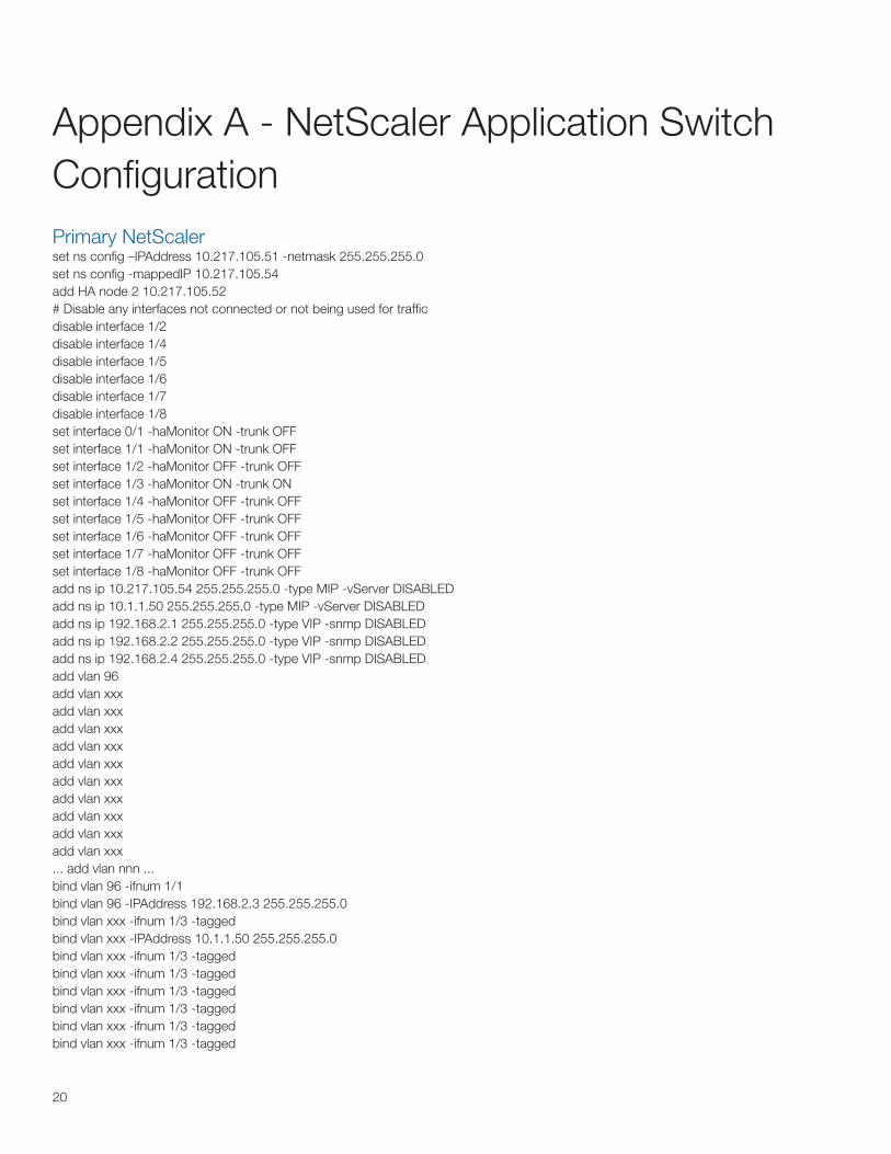
Appendix A - NetScaler Application Switch ConfigurationPrimary NetScalerset ns config –IPAddress 10.217.105.51 -netmask 255.255.255.0set ns config -mappedIP 10.217.105.54 add HA node 2 10.217.105.52# Disable any interfaces not connected or not being used for trafficdisable interface 1/2disable interface 1/4disable interface 1/5disable interface 1/6disable interface 1/7disable interface 1/8set interface 0/1 -haMonitor ON -trunk OFF set interface 1/1 -haMonitor ON -trunk OFF set interface 1/2 -haMonitor OFF -trunk OFFset interface 1/3 -haMonitor ON -trunk ON set interface 1/4 -haMonitor OFF -trunk OFFset interface 1/5 -haMonitor OFF -trunk OFF set interface 1/6 -haMonitor OFF -trunk OFF set interface 1/7 -haMonitor OFF -trunk OFFset interface 1/8 -haMonitor OFF -trunk OFF add ns ip 10.217.105.54 255.255.255.0 -type MIP -vServer DISABLEDadd ns ip 10.1.1.50 255.255.255.0 -type MIP -vServer DISABLEDadd ns ip 192.168.2.1 255.255.255.0 -type VIP -snmp DISABLEDadd ns ip 192.168.2.2 255.255.255.0 -type VIP -snmp DISABLEDadd ns ip 192.168.2.4 255.255.255.0 -type VIP -snmp DISABLEDadd vlan 96add vlan xxxadd vlan xxxadd vlan xxxadd vlan xxxadd vlan xxxadd vlan xxxadd vlan xxxadd vlan xxxadd vlan xxxadd vlan xxx... add vlan nnn ...bind vlan 96 -ifnum 1/1bind vlan 96 -IPAddress 192.168.2.3 255.255.255.0bind vlan xxx -ifnum 1/3 -taggedbind vlan xxx -IPAddress 10.1.1.50 255.255.255.0bind vlan xxx -ifnum 1/3 -taggedbind vlan xxx -ifnum 1/3 -taggedbind vlan xxx -ifnum 1/3 -taggedbind vlan xxx -ifnum 1/3 -taggedbind vlan xxx -ifnum 1/3 -taggedbind vlan xxx -ifnum 1/3 -tagged
21
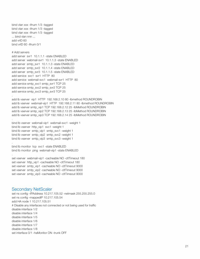
bind vlan xxx -ifnum 1/3 -taggedbind vlan xxx -ifnum 1/3 -taggedbind vlan xxx -ifnum 1/3 -tagged... bind vlan nnn ...add vrID 60bind vrID 60 -ifnum 0/1
# Add serversadd server svr1 10.1.1.1 -state ENABLEDadd server webmail-svr1 10.1.1.3 -state ENABLEDadd server smtp_svr1 10.1.1.3 -state ENABLEDadd server smtp_svr2 10.1.1.4 -state ENABLEDadd server smtp_svr3 10.1.1.5 -state ENABLEDadd service svc1 svr1 HTTP 80 add service webmail-svc1 webmail-svr1 HTTP 80 add service smtp_svc1 smtp_svr1 TCP 25add service smtp_svc2 smtp_svr2 TCP 25add service smtp_svc3 smtp_svr3 TCP 25.add lb vserver vip1 HTTP 192.168.2.10 80 -lbmethod ROUNDROBINadd lb vserver webmail-vip1 HTTP 192.168.2.11 80 -lbmethod ROUNDROBINadd lb vserver smtp_vip1 TCP 192.168.2.12 25 -lbMethod ROUNDROBINadd lb vserver smtp_vip2 TCP 192.168.2.13 25 -lbMethod ROUNDROBINadd lb vserver smtp_vip3 TCP 192.168.2.14 25 -lbMethod ROUNDROBIN.bind lb vserver webmail-vip1 webmail-svc1 -weight 1bind lb vserver http_vip1 svc1 -weight 1bind lb vserver smtp_vip1 smtp_svc1 -weight 1bind lb vserver smtp_vip2 smtp_svc2 -weight 1bind lb vserver smtp_vip3 smtp_svc3 -weight 1.bind lb monitor tcp svc1 -state ENABLEDbind lb monitor ping webmail-vip1 -state ENABLED.set vserver webmail-vip1 -cacheable NO -cltTimeout 180set vserver http_vip1 -cacheable NO -cltTimeout 180set vserver smtp_vip1 -cacheable NO -cltTimeout 9000set vserver smtp_vip2 -cacheable NO -cltTimeout 9000set vserver smtp_vip3 -cacheable NO -cltTimeout 9000
Secondary NetScalerset ns config –IPAddress 10.217.105.52 -netmask 255.255.255.0set ns config -mappedIP 10.217.105.54 add HA node 1 10.217.105.51# Disable any interfaces not connected or not being used for trafficdisable interface 1/2disable interface 1/4disable interface 1/5disable interface 1/6disable interface 1/7disable interface 1/8set interface 0/1 -haMonitor ON -trunk OFF

22
set interface 1/1 -haMonitor ON -trunk OFF set interface 1/2 -haMonitor OFF -trunk OFFset interface 1/3 -haMonitor ON -trunk ON set interface 1/4 -haMonitor OFF -trunk OFFset interface 1/5 -haMonitor OFF -trunk OFF set interface 1/6 -haMonitor OFF -trunk OFF set interface 1/7 -haMonitor OFF -trunk OFFset interface 1/8 -haMonitor OFF -trunk OFF add vlan 96add vlan xxxadd vlan xxxadd vlan xxxadd vlan xxxadd vlan xxxadd vlan xxxadd vlan xxxadd vlan xxxadd vlan xxxadd vlan xxx... add vlan nnn ...bind vlan 96 -ifnum 1/1bind vlan 96 -IPAddress 192.168.2.3 255.255.255.0bind vlan xxx -ifnum 1/3 -taggedbind vlan xxx -IPAddress 10.1.1.50 255.255.255.0bind vlan xxx -ifnum 1/3 -taggedbind vlan xxx -ifnum 1/3 -taggedbind vlan xxx -ifnum 1/3 -taggedbind vlan xxx -ifnum 1/3 -taggedbind vlan xxx -ifnum 1/3 -taggedbind vlan xxx -ifnum 1/3 -taggedbind vlan xxx -ifnum 1/3 -taggedbind vlan xxx -ifnum 1/3 -taggedbind vlan xxx -ifnum 1/3 -tagged... bind vlan nnn ...add vrID 60bind vrID 60 -ifnum 0/1 ...... Secondary will Sync to Primary...
23
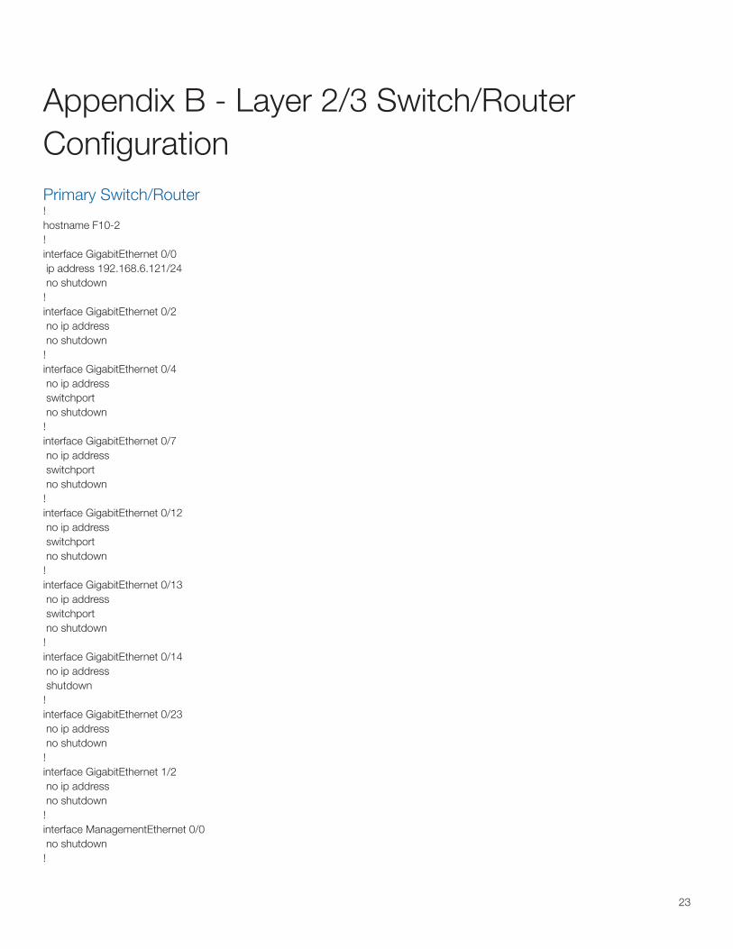
Appendix B - Layer 2/3 Switch/Router ConfigurationPrimary Switch/Router!hostname F10-2!interface GigabitEthernet 0/0 ip address 192.168.6.121/24 no shutdown!interface GigabitEthernet 0/2 no ip address no shutdown!interface GigabitEthernet 0/4 no ip address switchport no shutdown!interface GigabitEthernet 0/7 no ip address switchport no shutdown!interface GigabitEthernet 0/12 no ip address switchport no shutdown!interface GigabitEthernet 0/13 no ip address switchport no shutdown!interface GigabitEthernet 0/14 no ip address shutdown!interface GigabitEthernet 0/23 no ip address no shutdown!interface GigabitEthernet 1/2 no ip address no shutdown!interface ManagementEthernet 0/0 no shutdown!

24
interface ManagementEthernet 1/0 ip address 192.168.0.1/24 no shutdown!interface Port-channel 1 ip address 192.168.39.138/24 channel-member GigabitEthernet 0/2 channel-member GigabitEthernet 1/2 no shutdown!interface Port-channel 10 no ip address switchport channel-member GigabitEthernet 0/23 channel-member GigabitEthernet 1/3 no shutdown!interface Vlan 96 ip address 192.168.59.251/24 tagged Port-channel 10 untagged GigabitEthernet 0/12 no ip proxy-arp! vrrp-group 7 advertise-interval 5 priority 40 virtual-address 10.1.1.254! vrrp-group 9 advertise-interval 5 priority 50 virtual-address 10.1.1.253 no shutdown!interface Vlan xxx no ip address tagged GigabitEthernet 0/7,13 no shutdown!interface Vlan xxx ip address 10.1.3.251/24 tagged GigabitEthernet 0/4,13 no shutdown!interface Vlan xxx ip address 10.1.4.251/24 tagged GigabitEthernet 0/4,13 no shutdown!interface Vlan xxx ip address 10.1.5.251/24 tagged GigabitEthernet 0/4,13 no shutdown!
25
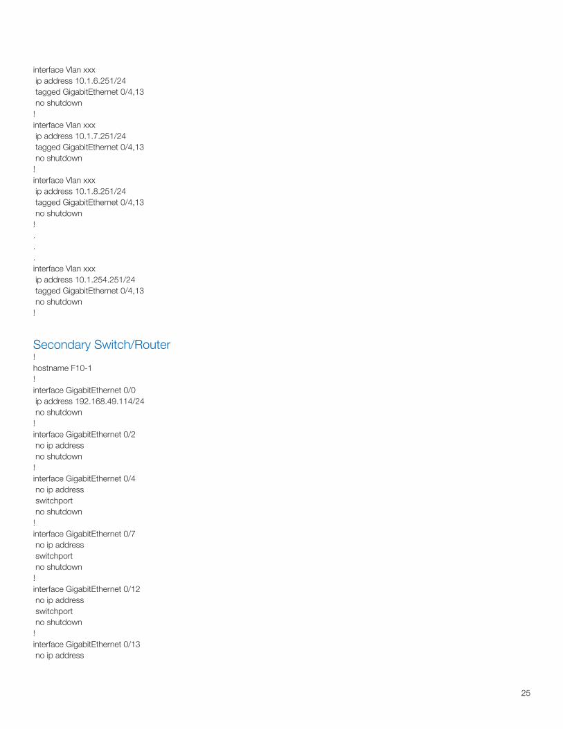
interface Vlan xxx ip address 10.1.6.251/24 tagged GigabitEthernet 0/4,13 no shutdown!interface Vlan xxx ip address 10.1.7.251/24 tagged GigabitEthernet 0/4,13 no shutdown!interface Vlan xxx ip address 10.1.8.251/24 tagged GigabitEthernet 0/4,13 no shutdown!...interface Vlan xxx ip address 10.1.254.251/24 tagged GigabitEthernet 0/4,13 no shutdown!
Secondary Switch/Router!hostname F10-1!interface GigabitEthernet 0/0 ip address 192.168.49.114/24 no shutdown!interface GigabitEthernet 0/2 no ip address no shutdown!interface GigabitEthernet 0/4 no ip address switchport no shutdown!interface GigabitEthernet 0/7 no ip address switchport no shutdown!interface GigabitEthernet 0/12 no ip address switchport no shutdown!interface GigabitEthernet 0/13 no ip address

26
switchport no shutdown!interface GigabitEthernet 0/14 no ip address no shutdown!interface GigabitEthernet 0/23 no ip address no shutdown!interface GigabitEthernet 1/2 no ip address no shutdown!interface ManagementEthernet 0/0 no shutdown!interface ManagementEthernet 1/0 ip address 172.31.1.31/24 no shutdown!interface Port-channel 1 ip address 192.168.39.137/24 channel-member GigabitEthernet 0/2 channel-member GigabitEthernet 1/2 no shutdown!interface Port-channel 10 no ip address switchport channel-member GigabitEthernet 0/23 channel-member GigabitEthernet 1/3 no shutdown!interface Vlan 96 ip address 192.168.59.252/24 tagged Port-channel 10 untagged GigabitEthernet 0/12 no ip proxy-arp! vrrp-group 7 advertise-interval 5 priority 50 virtual-address 192.168.59.254! vrrp-group 9 advertise-interval 5 priority 40 virtual-address 192.168.59.253 no shutdown!interface Vlan xxx ip address 10.1.1.252/24

27
ip address 172.21.1.254/24 secondary tagged GigabitEthernet 0/4,13 track ip GigabitEthernet 0/4 no ip proxy-arp!interface Vlan xxx no ip address tagged GigabitEthernet 0/7,13 no shutdown!interface Vlan xxx ip address 10.1.3.252/24 tagged GigabitEthernet 0/4,13 no shutdown!interface Vlan xxx ip address 10.1.4.252/24 tagged GigabitEthernet 0/4,13 no shutdown!interface Vlan xxx ip address 10.1.5.252/24 tagged GigabitEthernet 0/4,13 no shutdown!interface Vlan xxx ip address 10.1.6.252/24 tagged GigabitEthernet 0/4,13 no shutdown!interface Vlan xxx ip address 10.1.7.252/24 tagged GigabitEthernet 0/4,13 no shutdown!interface Vlan xxx ip address 10.1.8.252/24 tagged GigabitEthernet 0/4,13 no shutdown!interface Vlan xxx ip address 10.1.254.252/24 tagged GigabitEthernet 0/4,13 no shutdown!
28
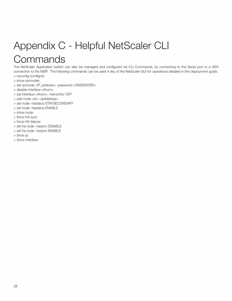
Appendix C - Helpful NetScaler CLI CommandsThe NetScaler Application switch can also be managed and configured via CLI Commands, by connecting to the Serial port or a SSH connection to the NSIP. The following commands can be used in lieu of the NetScaler GUI for operations detailed in this deployment guide.> nsconfig (configns)> show rpcnodes> set rpcnode <IP_address> -password <PASSWORD>> disable interface <ifnum>> set interface <ifnum> -hamonitor OFF> add node <id> <ipAddress>> set node -hastatus STAYSECONDARY > set node -hastatus ENABLE> show node> force HA sync> force HA failover> set ha node –hasync DISABLE> set ha node –hasync ENABLE> show ip> show interface
www.citrix.com
Citrix WorldwideWorldwide headquarters
Citrix Systems, Inc.851 West Cypress Creek RoadFort Lauderdale, FL 33309USAT +1 800 393 1888T +1 954 267 3000
Regional headquarters
AmericasCitrix Silicon Valley4988 Great America ParkwaySanta Clara, CA 95054USAT +1 408 790 8000
EuropeCitrix Systems International GmbHRheinweg 98200 SchaffhausenSwitzerlandT +41 52 635 7700
Asia PacificCitrix Systems Hong Kong Ltd.Suite 3201, 32nd FloorOne International Finance Centre1 Harbour View StreetCentralHong KongT +852 2100 5000
Citrix Online division5385 Hollister AvenueSanta Barbara, CA 93111USAT +1 805 690 6400
www.citrix.com
About CitrixCitrix Systems, Inc. (Nasdaq:CTXS) is the global leader and the most trusted name in application delivery infrastructure. More than 200,000 organizations worldwide rely on Citrix to deliver any application to users anywhere with the best performance, highest security and lowest cost. Citrix customers include 100% of the Fortune 100 companies and 98% of the Fortune Global 500, as well as hundreds of thousands of small businesses and prosumers. Citrix has approximately 6,200 channel and alliance partners in more than 100 countries. Annual revenue in 2006 was $1.1 billion.
Citrix®, NetScaler®, GoToMyPC®, GoToMeeting®, GoToAssist®, Citrix Presentation Server™, Citrix Password Manager™, Citrix Access Gateway™, Citrix Access Essentials™, Citrix Access Suite™, Citrix SmoothRoaming™ and Citrix Subscription Advantage™ and are trademarks of Citrix Systems, Inc. and/or one or more of its subsidiaries, and may be registered in the U.S. Patent and Trademark Office and in other countries. UNIX® is a registered trademark of The Open Group in the U.S. and other countries. Microsoft®, Windows® and Windows Server® are registered trademarks of Microsoft Corporation in the U.S. and/or other countries. All other trademarks and registered trademarks are property of their respective owners.