Deploying Metro Ethernet Solutions V3 - cisco.com · Deploying Metro Ethernet Solutions ... 100 120...
96
© 2002, Cisco Systems, Inc. All rights reserved. ACC-213 5058_04_2002_c1 1
-
Upload
hoangduong -
Category
Documents
-
view
227 -
download
0
Transcript of Deploying Metro Ethernet Solutions V3 - cisco.com · Deploying Metro Ethernet Solutions ... 100 120...

© 2002, Cisco Systems, Inc. All rights reserved.
ACC-2135058_04_2002_c1 1

2© 2002, Cisco Systems, Inc. All rights reserved.
Deploying Metro Ethernet Solutions
Joe Deveaux, CSE
333© 2002, Cisco Systems, Inc. All rights reserved.
Deploying Metro Ethernet Solutions
• Metro Services Evolution
• Designing with Fiber
• Designing with 10 Gigabit Ethernet
• Ethernet TLS
• Design Principles
• Metro Ethernet Design Recommendations
• Cisco Metro Solutions
Agenda
444© 2002, Cisco Systems, Inc. All rights reserved.
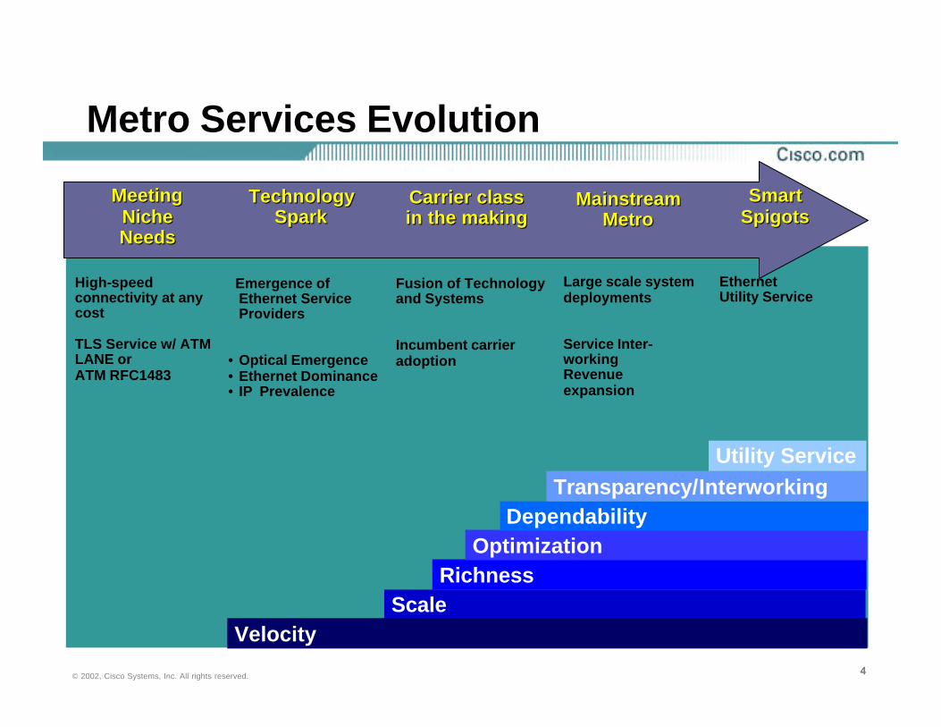
Metro Services Evolution
High-speed connectivity at any cost
TLS Service w/ ATM LANE or ATM RFC1483
Emergence of Ethernet Service Providers
• Optical Emergence• Ethernet Dominance• IP Prevalence
Fusion of Technology and Systems
Incumbent carrier adoption
Large scale systemdeployments
Service Inter-workingRevenue expansion
Ethernet Utility Service
Scale Velocity
Richness Optimization
Dependability Transparency/Interworking
Utility Service
Meeting NicheNeeds
Meeting NicheNeeds
TechnologySpark
TechnologySpark
Carrier class in the makingCarrier class in the making
Mainstream Metro
Mainstream Metro
Smart SpigotsSmart
Spigots

555© 2002, Cisco Systems, Inc. All rights reserved.
Fiber Build-Out Changes Metro
• Fiber reaching 20% of enterprises and growing
• Enterprise looking for interface consolidation of services
• Speed/cost/provisioning advantages
• Large scale network architecture
• Business model required
• Opportunity for value-added services (content, voice, etc..)
FiberInternet Site
Interconnect
Storage Remote Access
ETTB
ETTS
Internet VoD
Voice Services
Content

666© 2002, Cisco Systems, Inc. All rights reserved.
Internet
Storage
BranchOffice
Multiple 45 Mbps
Multiple 1.5 Mbps
45 Mbps
45 Mbps
Large Price Mismatch Between T1s and T3 Service
PSTN
10x Bandwidth Mismatch Between LAN and MAN
Transporting Data Over a Voice Network
Long Service Provisioning Times
Challenges In Managing Data Networks
Cannot ProvisionAcross the Data and Transport Network
Converged Network for Cost Savings
EnterpriseEnterprise
Service ProviderService Provider
Metro Bandwidth and Service Issues

777© 2002, Cisco Systems, Inc. All rights reserved.
FR/ATM Services today
Service Provider FR/ATM Core
Headquarters
T1 Service
“Bandwidth Constrained”
Branch Office
Branch Office
Branch Office
T1
T1
T1
Other ExistingFR/ATMCustomers
Service provider offerings limited: n x T1n x T3

888© 2002, Cisco Systems, Inc. All rights reserved.
FR/ATM Services today
Service Provider FR/ATM Core
Headquarters
T3 Service
Branch Office
Branch Office
Branch Office
T1
T1
T1
Other ExistingFR/ATMCustomers
Service provider offerings limited: n x T1n x T3

999© 2002, Cisco Systems, Inc. All rights reserved.
FR/ATM Services today
Service Provider FR/ATM Core
Headquarters
OC-3 Service
Branch Office
Branch Office
Branch Office
T1
T1
T1
Other ExistingFR/ATMCustomers
Service provider offerings limited: n x T1n x T3

101010© 2002, Cisco Systems, Inc. All rights reserved.
Metro Ethernet Service Provider Value
0
20
40
60
80
100
120
140
160
0 20 40 60 80 100
Customer Need (Mbps)
Ser
vice
(Mb
ps)
DS3Ethernet
STM1
E3 ETHERNET
Meet End Customer’s Growing Bandwidth Requirement Without Network Infrastructure Change
ReduceReduceCapExCapEx && OpEx OpEx
111111© 2002, Cisco Systems, Inc. All rights reserved.
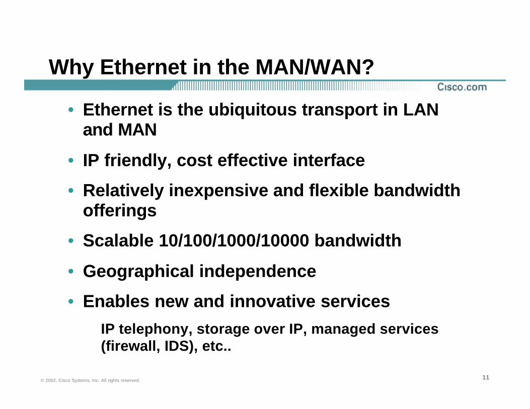
Why Ethernet in the MAN/WAN?
• Ethernet is the ubiquitous transport in LAN and MAN
• IP friendly, cost effective interface
• Relatively inexpensive and flexible bandwidth offerings
• Scalable 10/100/1000/10000 bandwidth
• Geographical independence
• Enables new and innovative servicesIP telephony, storage over IP, managed services (firewall, IDS), etc..

121212© 2002, Cisco Systems, Inc. All rights reserved.
Application Requirements Drive Metro Networking Solution
• LAN interconnect
• Service aggregation
• Interconnect data centers
• Backup and disaster recovery
• Connect to hosting services
• Value-added Services
High Bandwidth
Low Latency
TransparentServices
HighAvailability
Cost Effective
Manageable and Secure

131313© 2002, Cisco Systems, Inc. All rights reserved.
What Problems Are Enterprises Trying to Solve?
Networks that Deliver on This Requirement:• Have consistently high performance packet forwarding
• Are reliable and available
• Are service enabling
• Are cost efficient
How You Deliver This Is Largely IrrelevantMetro Ethernet Is Simply a Tool in the Tool Box
The Requirement Is for Enterprise ApplicationsTo Be Available and Perform Well
141414© 2002, Cisco Systems, Inc. All rights reserved.
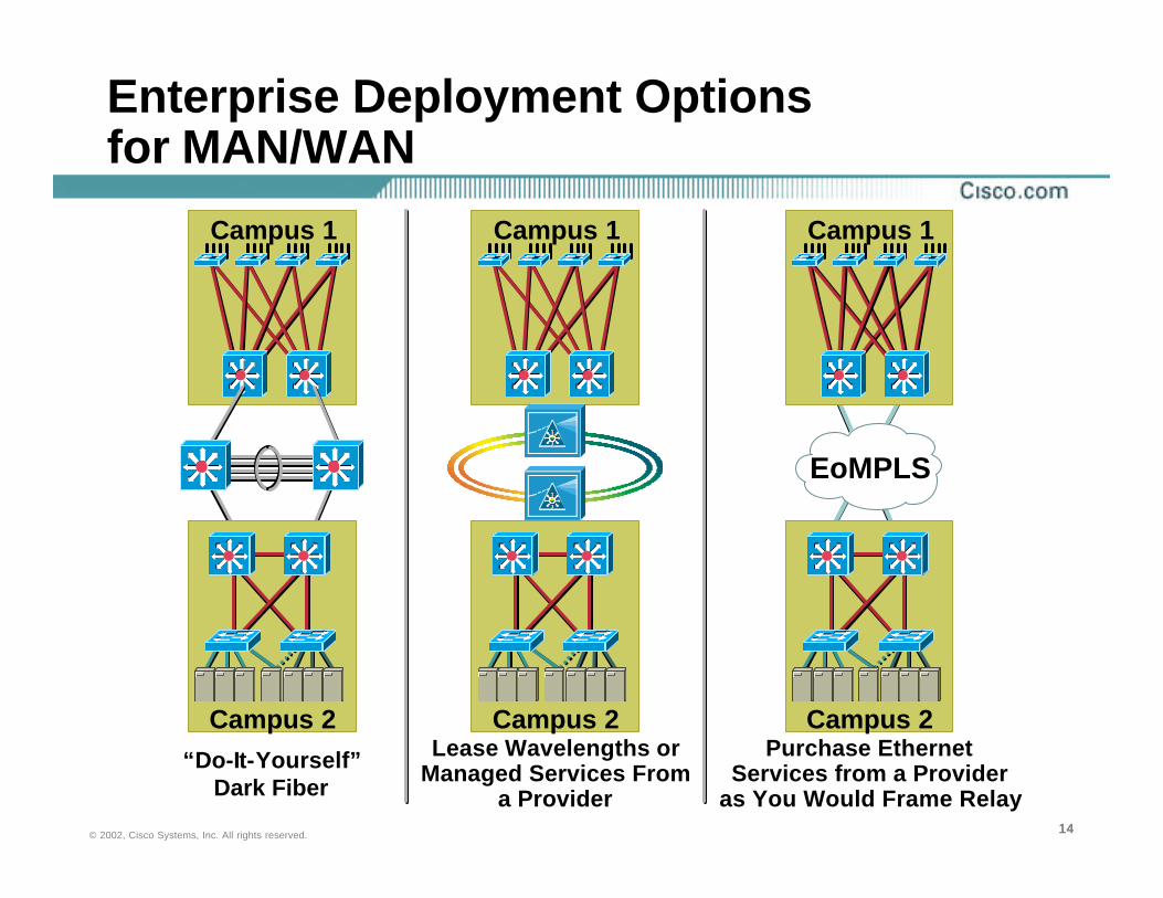
Enterprise Deployment Options for MAN/WAN
“Do-It-Yourself”Dark Fiber
Lease Wavelengths or Managed Services From
a Provider
Purchase EthernetServices from a Provider
as You Would Frame Relay
Campus 1
Campus 2
Campus 1 Campus 1
Campus 2 Campus 2
EoMPLS

151515© 2002, Cisco Systems, Inc. All rights reserved.
Which Technologies Do I Use?
• LAN interconnect
• Service aggregation
• Data center interconnect
• Backup and disaster recovery
• Bulk data replication
• Storage consolidation
• Connection to hosting services
• Dark Fiber
• Existing edge equipment
Ethernet
SONET
Frame Relay
ATM
DWDM
• Bandwidth requirements
Application Requirements
Application Requirements What Exists TodayWhat Exists Today
161616© 2002, Cisco Systems, Inc. All rights reserved.
Metro Ethernet: Revolution or Evolution?
• Question: How does metro Ethernet change the way we design and deploy networks?
• Answer: Nothing changes; the same principles of structure and hierarchy still hold true
• Be aware that the service will dictate design considerations
171717© 2002, Cisco Systems, Inc. All rights reserved.
Deploying Metro Ethernet in the Enterprise
• Metro Services Evolution
• Designing with Fiber
• Designing with 10 Gigabit Ethernet
• Ethernet TLS
• Design Principles
• Metro Ethernet Design Recommendations
• Cisco Metro Solutions
Agenda

181818© 2002, Cisco Systems, Inc. All rights reserved.
Dark Fiber
• Access to dark fiber enables many technology choices to be made, but depends upon physical characteristics of fiber plant
How long is the fiber?
What is the fiber quality and type?
What is the optical power budget?
What is the attenuation/loss of the system?
Will amplification be required?
What are the dispersion characteristics?
Do I need to consider non-linear effects?
• All these questions must be considered and understood

191919© 2002, Cisco Systems, Inc. All rights reserved.
Dark Fiber: The Choices
• Once the physical characteristics are understood, then a technology and topology choice can be made
Point-to-point vs. ring
CWDM vs. DWDM
202020© 2002, Cisco Systems, Inc. All rights reserved.
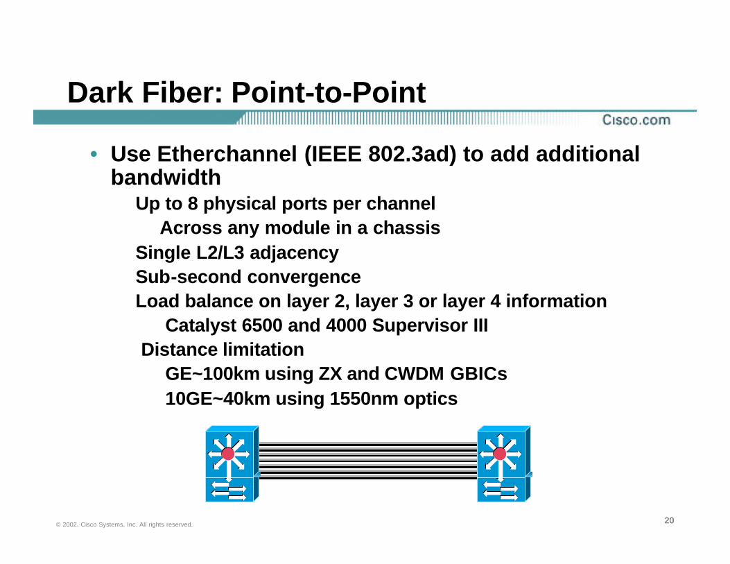
Dark Fiber: Point-to-Point
• Use Etherchannel (IEEE 802.3ad) to add additional bandwidth
Up to 8 physical ports per channelAcross any module in a chassis
Single L2/L3 adjacencySub-second convergenceLoad balance on layer 2, layer 3 or layer 4 information
Catalyst 6500 and 4000 Supervisor IIIDistance limitation
GE~100km using ZX and CWDM GBICs10GE~40km using 1550nm optics

212121© 2002, Cisco Systems, Inc. All rights reserved.
Dark Fiber: Ring Topologies
• GE rings are cost effective solution if…Traffic patterns and convergence characteristics are known and understood
• However, be aware of…Multi-hop routing or switchingBlocking using 802.1d/w/sTraffic aggregation will occur
Need to understand traffic patterns
• Solutions:Make ring appear as point-to-point connection using CWDM or DWDM
222222© 2002, Cisco Systems, Inc. All rights reserved.
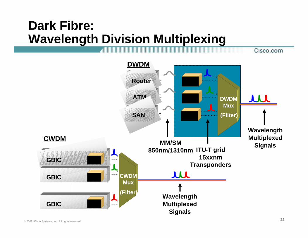
Dark Fibre:Wavelength Division Multiplexing
Wavelength Multiplexed
Signals
CWDMMux
(Filter)
GBIC EO
GBIC EO
GBIC EO
MM/SM850nm/1310nm ITU-T grid
15xxnm Transponders
Router
ATM DWDMMux
(Filter)
OEO
OEO
SAN OEO
CWDM
DWDM
Wavelength Multiplexed
Signals

232323© 2002, Cisco Systems, Inc. All rights reserved.
Dark Fiber: CWDM
• Coarse wavelength division multiplexingSimilar to DWDM but at coarser wavelengths
1470nm, 1490nm, 1510nm, 1530nm, 1550nm, 1570nm, 1590nm, 1610nm
GBIC form factor
Single technology (gigabit Ethernet)
DWDM recommended for FibreChannel, ESCON, etc.
Very cost effective
Long drive distance
~30dB budget = ~100Km
Cannot be optically amplified, only Ethernet
242424© 2002, Cisco Systems, Inc. All rights reserved.
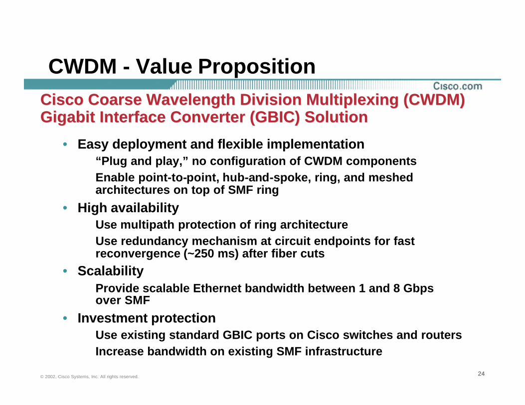
CWDM - Value Proposition
• Easy deployment and flexible implementation“Plug and play,” no configuration of CWDM componentsEnable point-to-point, hub-and-spoke, ring, and meshed architectures on top of SMF ring
• High availabilityUse multipath protection of ring architectureUse redundancy mechanism at circuit endpoints for fast reconvergence (~250 ms) after fiber cuts
• ScalabilityProvide scalable Ethernet bandwidth between 1 and 8 Gbps over SMF
• Investment protectionUse existing standard GBIC ports on Cisco switches and routersIncrease bandwidth on existing SMF infrastructure
Cisco Coarse Wavelength Division Multiplexing (CWDM) Cisco Coarse Wavelength Division Multiplexing (CWDM) Gigabit Interface Converter (GBIC) SolutionGigabit Interface Converter (GBIC) Solution

252525© 2002, Cisco Systems, Inc. All rights reserved.
Cisco CWDM GBIC SolutionBuilding Blocks
CWDM GBICs:
• 8 different “colored” GBICs
• Plug into GBIC slot on Cisco Catalyst® switch; connect to CWDM optical add-drop module (OADM) via SMF
CWDM OADM:• 3 versions for 1, 4, and 8
wavelengths (color)
• Mounted in 1-RU chassis
• OADMs connected via optical ring
262626© 2002, Cisco Systems, Inc. All rights reserved.
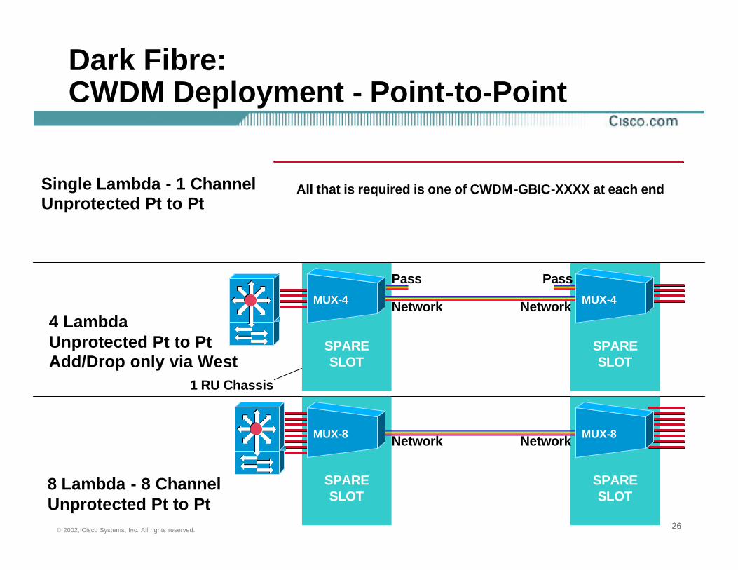
Dark Fibre: CWDM Deployment - Point-to-Point
MUX-4 MUX-4
Single Lambda - 1 ChannelUnprotected Pt to Pt
4 LambdaUnprotected Pt to PtAdd/Drop only via West
8 Lambda - 8 ChannelUnprotected Pt to Pt
Network Network
Pass Pass
1 RU Chassis
SPARESLOT
SPARESLOT
MUX-8 MUX-8Network Network
SPARESLOT
SPARESLOT
All that is required is one of CWDM-GBIC-XXXX at each end
272727© 2002, Cisco Systems, Inc. All rights reserved.
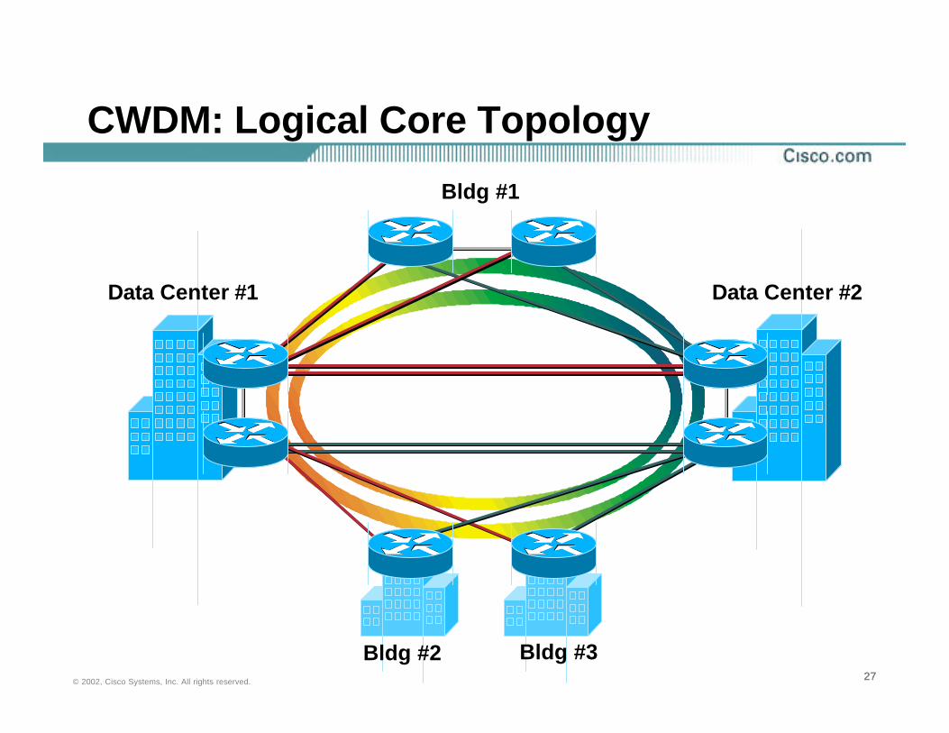
CWDM: Logical Core Topology
Data Center #1 Data Center #2
Bldg #3Bldg #2
Bldg #1
282828© 2002, Cisco Systems, Inc. All rights reserved.
SPARESLOT
SPARESLOT
SPARESLOT
SPARESLOT
MUX-8MUX-8MUX-8MUX-8
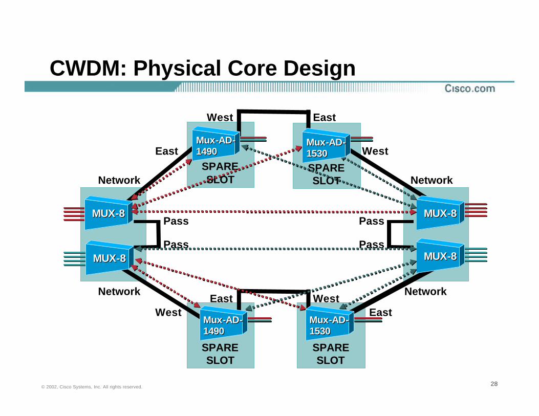
CWDM: Physical Core Design
MUX-8MUX-8
Network
Network
West
East
East
West
WestEast West
East
Network
Network
Pass
Pass
Pass
Pass
MUX-8MUX-8
Mux-AD-1530Mux-AD-1530
Mux-AD-1530Mux-AD-1530
Mux-AD-1490Mux-AD-1490
Mux-AD-1490Mux-AD-1490
292929© 2002, Cisco Systems, Inc. All rights reserved.
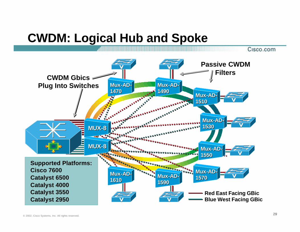
CWDM: Logical Hub and Spoke
Red East Facing GBicBlue West Facing GBic
Supported Platforms:Cisco 7600Catalyst 6500Catalyst 4000Catalyst 3550Catalyst 2950
Passive CWDM Filters
CWDM GbicsPlug Into Switches
MUX-8MUX-8
MUX-8MUX-8Mux-AD-1530Mux-AD-1530
Mux-AD-1470Mux-AD-1470
Mux-AD-1490Mux-AD-1490
Mux-AD-1510Mux-AD-1510
Mux-AD-1550Mux-AD-1550
Mux-AD-1570Mux-AD-1570Mux-AD-
1590Mux-AD-1590
Mux-AD-1610Mux-AD-1610
303030© 2002, Cisco Systems, Inc. All rights reserved.
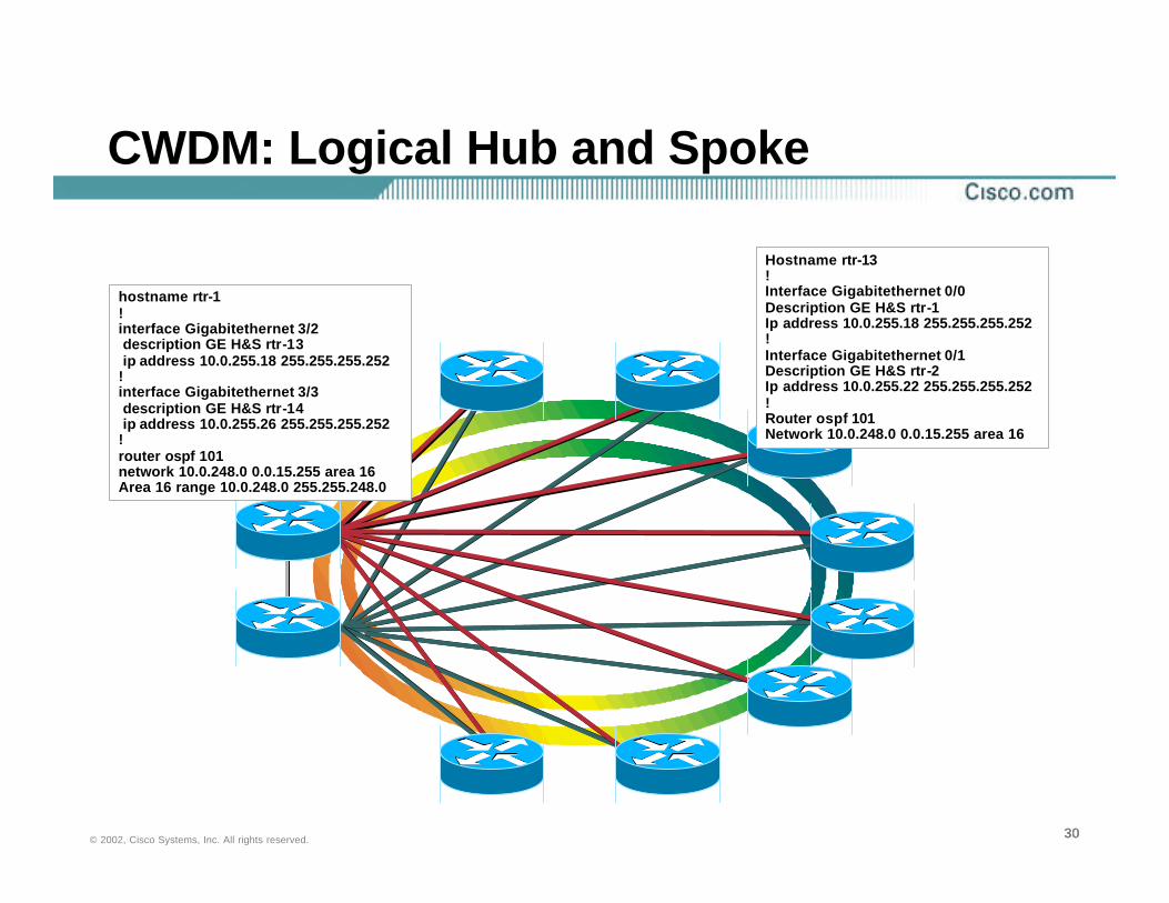
CWDM: Logical Hub and Spoke
hostname rtr-1!interface Gigabitethernet 3/2description GE H&S rtr-13ip address 10.0.255.18 255.255.255.252
!interface Gigabitethernet 3/3description GE H&S rtr-14ip address 10.0.255.26 255.255.255.252
!router ospf 101network 10.0.248.0 0.0.15.255 area 16Area 16 range 10.0.248.0 255.255.248.0
Hostname rtr-13!Interface Gigabitethernet 0/0Description GE H&S rtr-1Ip address 10.0.255.18 255.255.255.252!Interface Gigabitethernet 0/1Description GE H&S rtr-2Ip address 10.0.255.22 255.255.255.252!Router ospf 101Network 10.0.248.0 0.0.15.255 area 16
313131© 2002, Cisco Systems, Inc. All rights reserved.
DWDM and CWDM
• DWDM if you have multiple transport technologies is bit rate and transport transparent
Best choice Fiber channel, ESCON, SONET/SDH and LAN
Supports ring, BUS and star topologiesSupports wavelength protection switching
BLSR, UPSR, etc..Can be amplified
• CWDM GBICs are a single transport technologyGood choice if gigabit Ethernet only is requiredEvolution to 1550nm DWDM friendly opticsGood drive distance
~100km point-to-point~30km ring (8 node ring)

323232© 2002, Cisco Systems, Inc. All rights reserved.
CWDM Summary
• Flexible design options using optical add/drop multiplexors
• Relatively inexpensive introduction to DWDM
• Viable alternative to 10GE using GEC
• Cost effective method of increasing fiber capacity
• Cost effective method of simplifying network topologies
Install coloured GBICs and implement optical add/drop muxes later
• Supported on Cisco 7600 and Catalyst 6500, 4000, 3550 and 2950 products

333333© 2002, Cisco Systems, Inc. All rights reserved.
Deploying Metro Ethernet in the Enterprise
• Metro Services Evolution
• Designing with Fiber
• Designing with 10 Gigabit Ethernet
• Ethernet TLS
• Design Principles
• Metro Ethernet Design Recommendations
• Cisco Metro Solutions
Agenda
343434© 2002, Cisco Systems, Inc. All rights reserved.
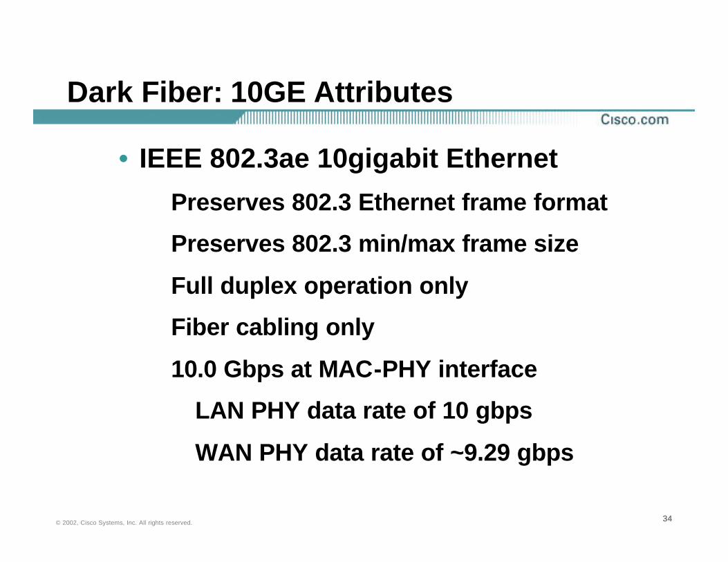
Dark Fiber: 10GE Attributes
• IEEE 802.3ae 10gigabit Ethernet
Preserves 802.3 Ethernet frame format
Preserves 802.3 min/max frame size
Full duplex operation only
Fiber cabling only
10.0 Gbps at MAC-PHY interface
LAN PHY data rate of 10 gbps
WAN PHY data rate of ~9.29 gbps

353535© 2002, Cisco Systems, Inc. All rights reserved.
10GE Optical Transceivers Physical Layer Dependant (PMD)
NOTES:
Distances Current with IEEE 802.3 Draft 3.3
*Draft 3.0 of the 802.3ae Specification References the Higher Bandwidth (2000 MHz*km) 50 Micron MM Fiber**The 9.0 Micron Value is the Core Diameter; ANSI/TIA/EIA-568-A Specifies That the Nominal “Mode Field Diameter “Shall be 8.7 to 10.0 Microns with a Tolerance of +/- 0.5 Micron at 1310 nm
850 nm Serial850 nm Serial
Fiber Supported
Fiber Supported
Diameter(Microns)Diameter(Microns)
Bandwidth(MHz*km)Bandwidth(MHz*km)
Distance(Meters)Distance(Meters)
1310 nm CWDM1310 nm CWDM
1310 nm Serial1310 nm Serial
1550 nm Serial1550 nm Serial
PMDPMD
MultimodeMultimode
MultimodeSingle ModeMultimode
Single Mode
Single ModeSingle Mode
Single ModeSingle Mode
50*50*
62.59.0**62.59.0**
9.09.0
9.09.0
400400
160NA160NA
NANA
NANA
6666
30010 k30010 k
10 k10 k
40 k40 k

363636© 2002, Cisco Systems, Inc. All rights reserved.
Metro Ethernet: 10GE Summary
• 10GE runs on single mode fiber today• Standard is complete 802.3ae• Pull single mode for new installations• Issues involving multimode fiber support are
complex• Cost effective MAN technology• Cisco is shipping 10GE on Catalyst 6500/7600
and 12000 todayRaising the bandwidth for L2–L7 services

373737© 2002, Cisco Systems, Inc. All rights reserved.
GEC, 10GE and CWDM Deployment Scenarios
Scenario 1: Spare Fiber
Use Gigabit Etherchannel
Scenario 3: Limited Fibre>40km
Use CWDM and GE Etherchannel
Scenario 3: Limited Fibre>40km
Use CWDM and GE Etherchannel
Scenario 2: Limited Fiber <40km10 Gigabit Ethernet
383838© 2002, Cisco Systems, Inc. All rights reserved.
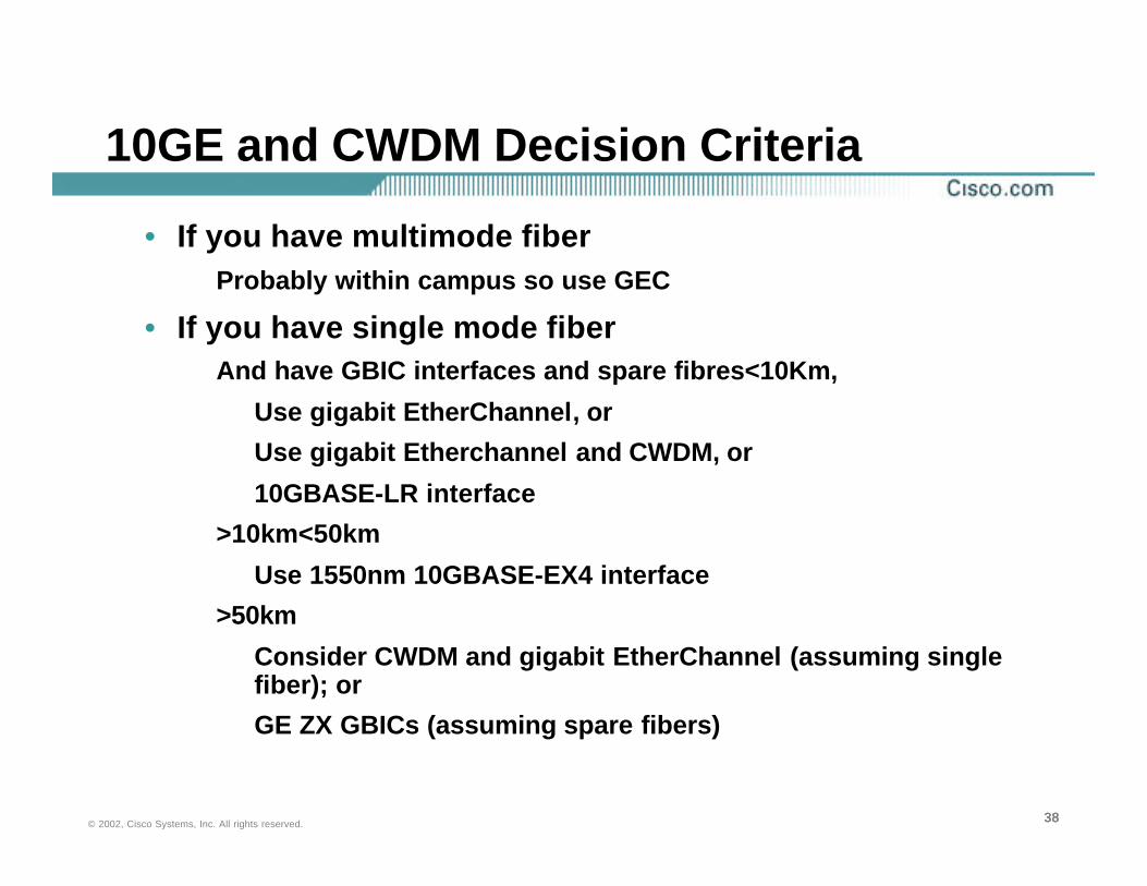
10GE and CWDM Decision Criteria
• If you have multimode fiber Probably within campus so use GEC
• If you have single mode fiberAnd have GBIC interfaces and spare fibres<10Km,
Use gigabit EtherChannel, or
Use gigabit Etherchannel and CWDM, or
10GBASE-LR interface
>10km<50km
Use 1550nm 10GBASE-EX4 interface
>50km
Consider CWDM and gigabit EtherChannel (assuming single fiber); or
GE ZX GBICs (assuming spare fibers)
393939© 2002, Cisco Systems, Inc. All rights reserved.
10GE and CWDM and DWDM
• 10GE, CWDM and DWDM are complimentary solutions
• Cisco CWDM provides flexible, cost effective Ethernet solutions today
• Wide Cisco support for CWDM across productsCisco 7600 and Catalyst 6500, 4000, 3550 and 2950 products
• 10GE is an economical, future proof solution todaySupported on Cisco 7600 and Catalyst 6500
• Cisco DWDM provides flexible, multi-transport optical solutions today

404040© 2002, Cisco Systems, Inc. All rights reserved.
Deploying Metro Ethernet in the Enterprise
• Metro Services Evolution
• Designing with Fiber
• Designing with 10 Gigabit Ethernet
• Ethernet TLS
• Design Principles
• Metro Ethernet Design Recommendations
• Cisco Metro Solutions
Agenda
414141© 2002, Cisco Systems, Inc. All rights reserved.
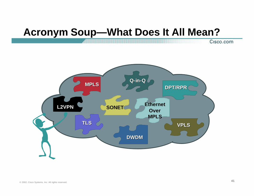
Acronym Soup—What Does It All Mean?
MPLSMPLS
SONET
DPT/RPRDPT/RPR
Ethernet Over MPLS
Q-in-QQ-in-Q
VPLSVPLS
DWDMDWDM
TLSTLS
L2VPNL2VPN
424242© 2002, Cisco Systems, Inc. All rights reserved.
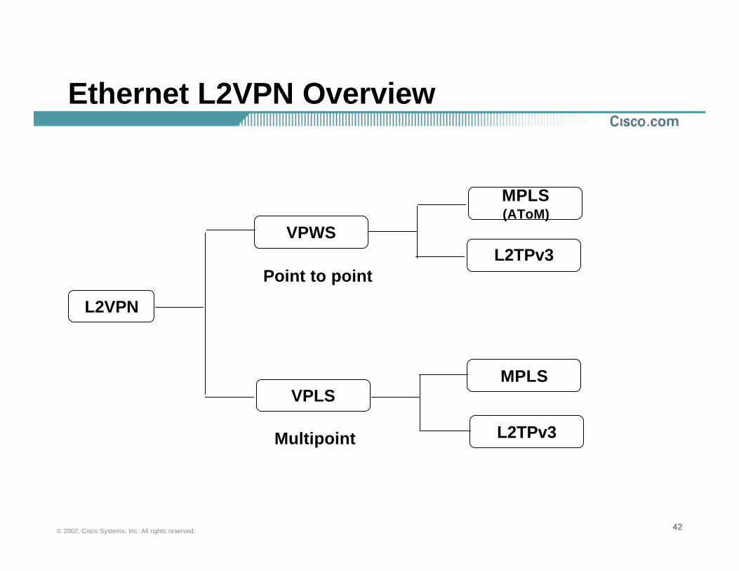
Ethernet L2VPN Overview
L2VPN
VPWS
VPLS
MPLS(AToM)
L2TPv3
MPLS
L2TPv3
Point to point
Multipoint

434343© 2002, Cisco Systems, Inc. All rights reserved.
VPWS
PE
PE
PE
CE-1
CE-2
CE-3
Attachment VCs
Emulated VC
Emulated Tunnel
444444© 2002, Cisco Systems, Inc. All rights reserved.
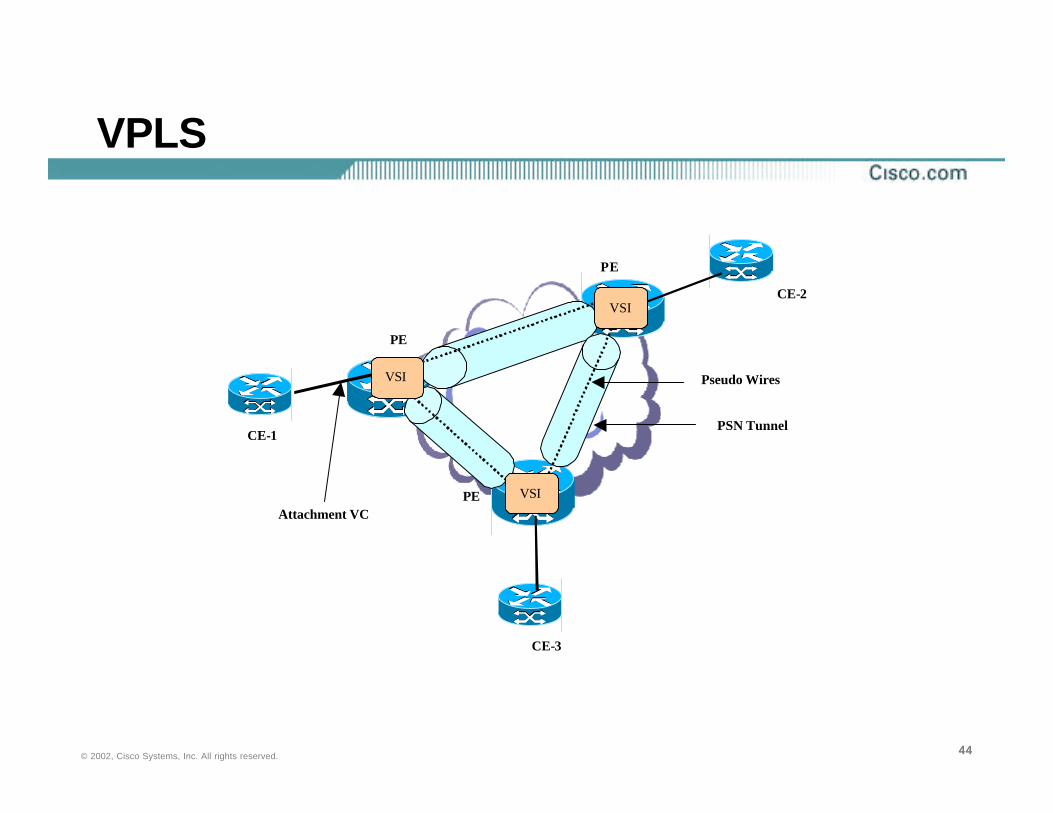
VPLS
PE
PE
PE
CE-1
CE-2
CE-3
Attachment VC
Pseudo Wires
PSN Tunnel
VSI
VSI
VSI
454545© 2002, Cisco Systems, Inc. All rights reserved.
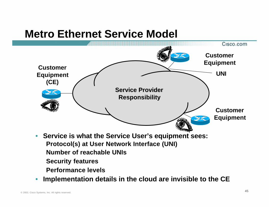
Metro Ethernet Service Model
• Service is what the Service User’s equipment sees:Protocol(s) at User Network Interface (UNI)Number of reachable UNIsSecurity featuresPerformance levels
• Implementation details in the cloud are invisible to the CE
Service ProviderService ProviderResponsibilityResponsibility
CustomerEquipment
(CE)
CustomerEquipment
CustomerEquipment
UNI

464646© 2002, Cisco Systems, Inc. All rights reserved.
CERouter
CECERouterRouter
Any-to-Any transport service that can be an alternative to unmanagedMPLS-VPN (or CsC). By using CE-routers there isNO issue with MAC table size in the PE’s. Layer 2 access is Ethernet only.
Similar to a Private Line service. Provided on a Shared Packet Network versus a TDM/OpticalNetwork (EPL). The CE-located equipment can bea router or a switch.
VPWSVPWS VPLSVPLS
ERSERS EWSEWS EMSEMS
CESwitch
CECESwitchSwitch
Similar to a Frame Relayservice where the DLCI becomes a VLAN and where a CIR + Burst is provided on a per VLAN basis.
X CERouter
CECERouterRouter
CESwitch
CECESwitchSwitch
CERouter
CECERouterRouter
CESwitch
CECESwitchSwitch
Service Definitions: A Summary

474747© 2002, Cisco Systems, Inc. All rights reserved.
Ethernet Relay Service (ERS)
The Frame Relay AnalogRequired Feature: Service Multiplexing (SM)
Service Multiplexing enables multiple instances of service to be multiplexed onto a single UNI, allowing that UNI to be in multiple ERS. Such a UNI is referred to as a Multiplexed UNI. When a UNI is in a single EVC, it is referred to as a Non-Multiplexed UNI.
B
A
CMultiplexed UNI
Non-Multiplexed UNI
Non-Multiplexed UNI
Using SM, service to B and C can be implemented at A without requiring two physical ports on the Customer Equipment at A
Note: ERS requires a 1:1 mapping association between CE-VLANs and ERS
484848© 2002, Cisco Systems, Inc. All rights reserved.
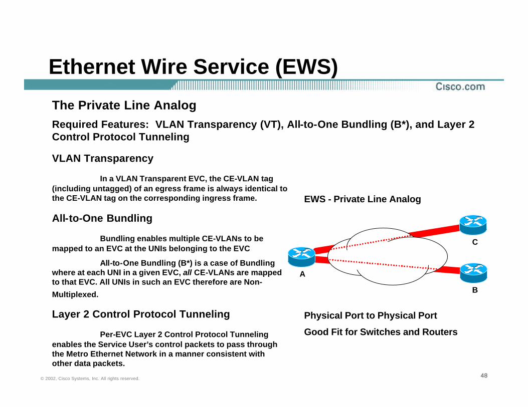
Ethernet Wire Service (EWS)
The Private Line AnalogRequired Features: VLAN Transparency (VT), All-to-One Bundling (B*), and Layer 2 Control Protocol Tunneling
VLAN Transparency
In a VLAN Transparent EVC, the CE-VLAN tag (including untagged) of an egress frame is always identical to the CE-VLAN tag on the corresponding ingress frame.
All-to-One Bundling
Bundling enables multiple CE-VLANs to be mapped to an EVC at the UNIs belonging to the EVC
All-to-One Bundling (B*) is a case of Bundling where at each UNI in a given EVC, all CE-VLANs are mapped to that EVC. All UNIs in such an EVC therefore are Non-
Multiplexed.
Layer 2 Control Protocol Tunneling
Per-EVC Layer 2 Control Protocol Tunneling enables the Service User’s control packets to pass through the Metro Ethernet Network in a manner consistent with other data packets.
Physical Port to Physical Port
Good Fit for Switches and Routers
A
B
EWS - Private Line Analog
C
494949© 2002, Cisco Systems, Inc. All rights reserved.
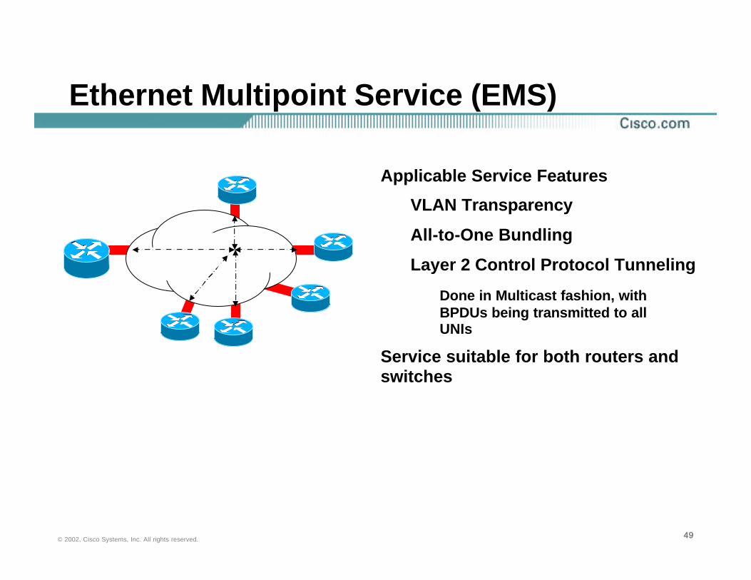
Ethernet Multipoint Service (EMS)
Applicable Service Features
VLAN Transparency
All-to-One Bundling
Layer 2 Control Protocol Tunneling
Done in Multicast fashion, with BPDUs being transmitted to all UNIs
Service suitable for both routers and switches

505050© 2002, Cisco Systems, Inc. All rights reserved.
Ethernet Multipoint Service (VPLS): A Customers Perspective
Customer Router
Customer Router
Customer Switch
Customer Switch
.1
.2
192.168.1.0/24
.13
.12
.11
Provider Edge
“Emulated LAN” Model“Emulated LAN” Model
515151© 2002, Cisco Systems, Inc. All rights reserved.
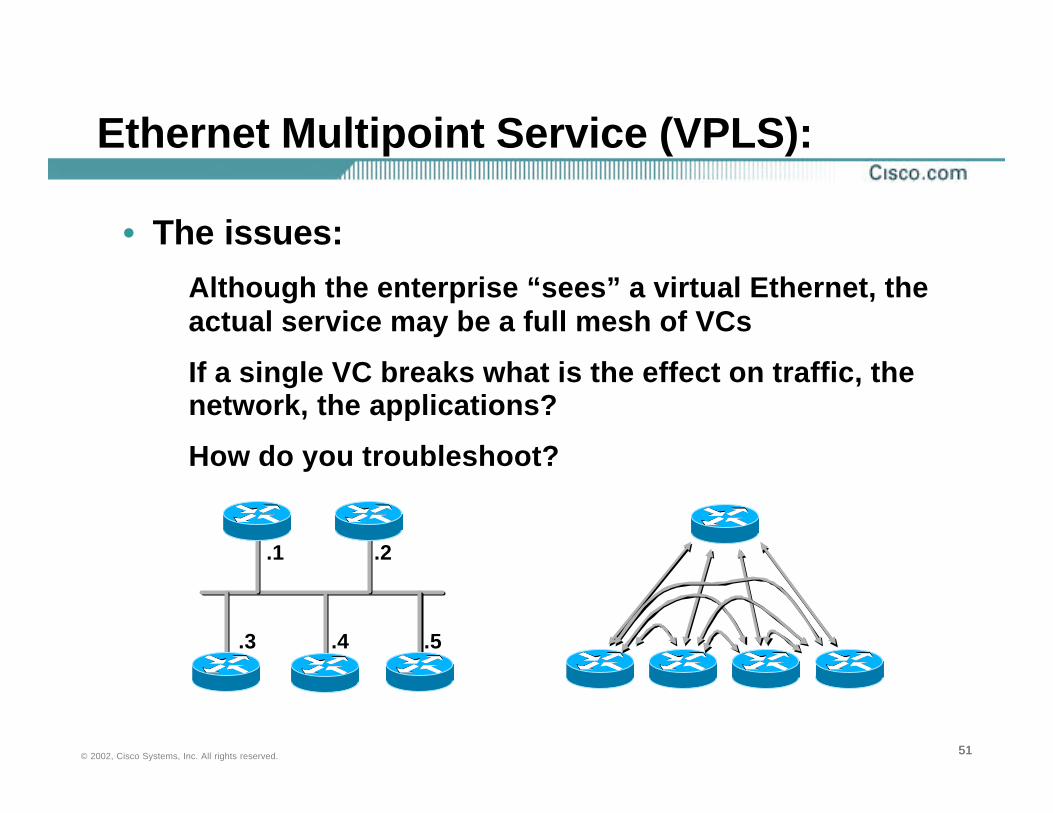
Ethernet Multipoint Service (VPLS):
• The issues:Although the enterprise “sees” a virtual Ethernet, the actual service may be a full mesh of VCs
If a single VC breaks what is the effect on traffic, the network, the applications?
How do you troubleshoot?
.1 .2
.5.4.3

525252© 2002, Cisco Systems, Inc. All rights reserved.
• “Emulated” LAN model
Each device is now a peer in it’s own right and consideration must be taken of…
Routing protocol interaction
Traffic patterns
QoS policies
Security policies
Troubleshooting
Ethernet Multipoint Service (VPLS):
535353© 2002, Cisco Systems, Inc. All rights reserved.
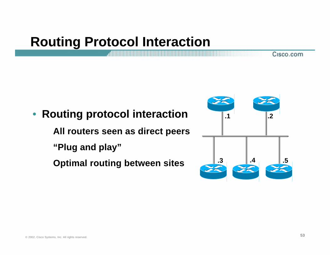
Routing Protocol Interaction
• Routing protocol interactionAll routers seen as direct peers
“Plug and play”
Optimal routing between sites
.1 .2
.5.4.3

545454© 2002, Cisco Systems, Inc. All rights reserved.
IP Multicast: OSPF and EIGRP
• Use caution when a portion of your network emulates a multi-access network but may not have consistent broadcast or multicast performance
—Router ADesignated Router
OSPF Hello(224.0.0.5
IP Multicast)
Example: SP Ethernet Transparent LAN Service
—Router B Backup Designated Router
555555© 2002, Cisco Systems, Inc. All rights reserved.
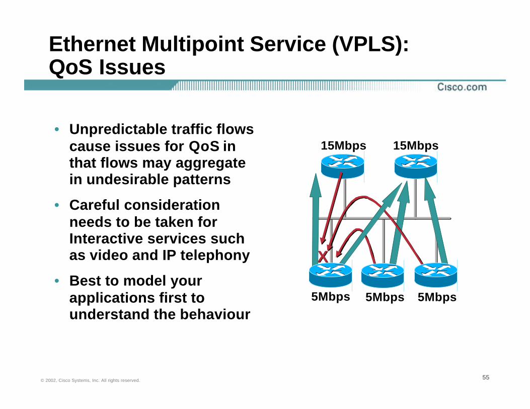
Ethernet Multipoint Service (VPLS): QoS Issues
• Unpredictable traffic flows cause issues for QoS in that flows may aggregate in undesirable patterns
• Careful consideration needs to be taken for Interactive services such as video and IP telephony
• Best to model your applications first to understand the behaviour
15Mbps 15Mbps
5Mbps 5Mbps5Mbps
XX
565656© 2002, Cisco Systems, Inc. All rights reserved.
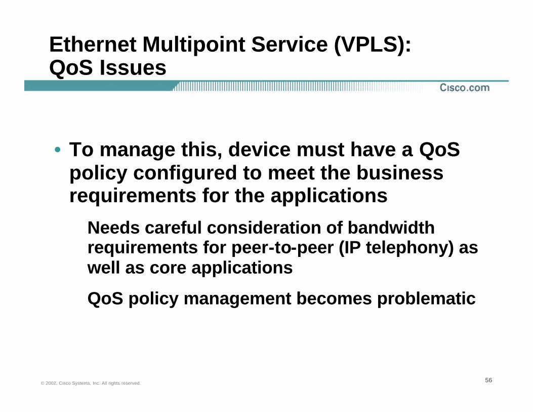
• To manage this, device must have a QoSpolicy configured to meet the business requirements for the applications
Needs careful consideration of bandwidth requirements for peer-to-peer (IP telephony) as well as core applications
QoS policy management becomes problematic
Ethernet Multipoint Service (VPLS): QoS Issues

575757© 2002, Cisco Systems, Inc. All rights reserved.
Metro Ethernet: Security
• Layer two switches present unique security concerns.
• DoS attacks– MAC address flooding/storms– Spanning tree attacks– CDP
• However, several mechanisms exist within Cisco IOS to increase security and protection of switched networks
• Need to protect yourself from the provider and vice versa
They will be protecting themselves too

585858© 2002, Cisco Systems, Inc. All rights reserved.
Metro Ethernet: Security Recommendations
• Disable VTP on edge switchesCould be used as a denial of service attack
• Disable CDP on all devicesAdvertises device, IP and software versions
Could be used as a DOS attack
• Disable DTP on edge switchesDefine only the VLANs that you require for connectivity
• Configure spanning tree ROOT guard
If switches are used to connect to provider network
595959© 2002, Cisco Systems, Inc. All rights reserved.
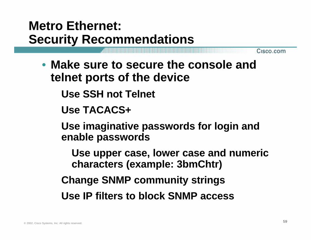
Metro Ethernet: Security Recommendations
• Make sure to secure the console and telnet ports of the device
Use SSH not Telnet
Use TACACS+
Use imaginative passwords for login and enable passwords
Use upper case, lower case and numeric characters (example: 3bmChtr)
Change SNMP community strings
Use IP filters to block SNMP access
606060© 2002, Cisco Systems, Inc. All rights reserved.
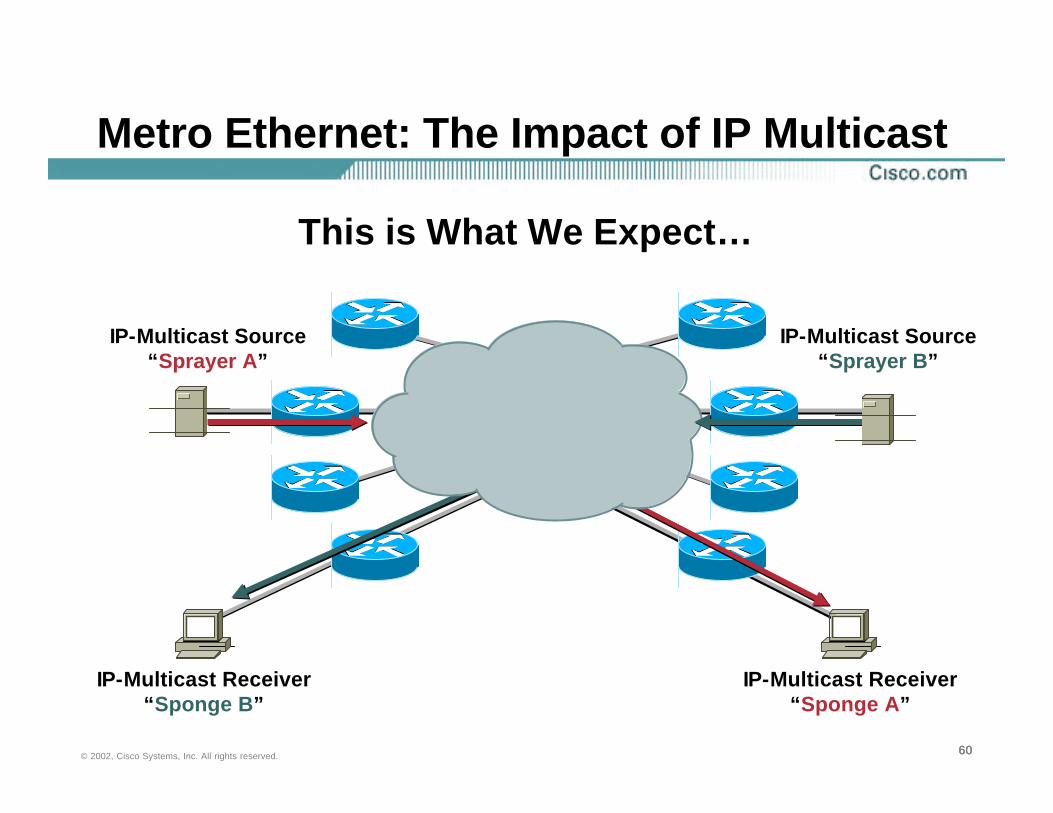
Metro Ethernet: The Impact of IP Multicast
IP-Multicast Source “Sprayer A”
IP-Multicast Source “Sprayer B”
IP-Multicast Receiver “Sponge A”
IP-Multicast Receiver “Sponge B”
This is What We Expect…
616161© 2002, Cisco Systems, Inc. All rights reserved.
IP-Multicast Source “Sprayer A”
IP-Multicast Source “Sprayer B”
IP-Multicast Receiver “Sponge A”
IP-Multicast Receiver “Sponge B”
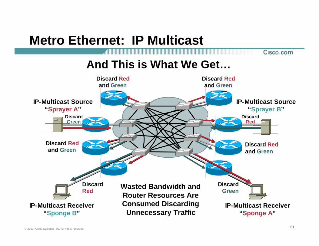
Metro Ethernet: IP Multicast
Wasted Bandwidth and Router Resources Are Consumed Discarding
Unnecessary Traffic
Discard Redand Green
Discard Green
Discard Red
Discard Red
Discard Green
Discard Redand Green
Discard Redand Green
Discard Redand Green
And This is What We Get…

626262© 2002, Cisco Systems, Inc. All rights reserved.
Metro Ethernet: IP Multicast
• The issue is that the routers are using PIM to join the multicast tree, and the switches use IGMP join messages to constrain forwarding
IGMP PIM Join
PIM??OK Rtr-A
Wants Group X. I’ll Forward
OK, Host A Wants Group X,
I’ll Ask Rtr-B
Rtr-A Rtr-B
636363© 2002, Cisco Systems, Inc. All rights reserved.
Metro EthernetConstrained Multicast Flooding
• L2 switches will flood broadcasts, multicasts and unknown unicasts
• L2 switches will use static multicast mac-address entries to constraint the flooding of multicast packets through:
CGMP: Control Plane Protocol between mcast router (Server) and CGMP-capable switch (Client), triggered by IGMP messages received by the CGMP Server
IGMP Snooping : L2 switch itself will snoop IGMP v2 join/leave message and install appropriate static cam entry
RGMP: to constraint flooding of mcast router to mcast router packets
Manual configuration
646464© 2002, Cisco Systems, Inc. All rights reserved.
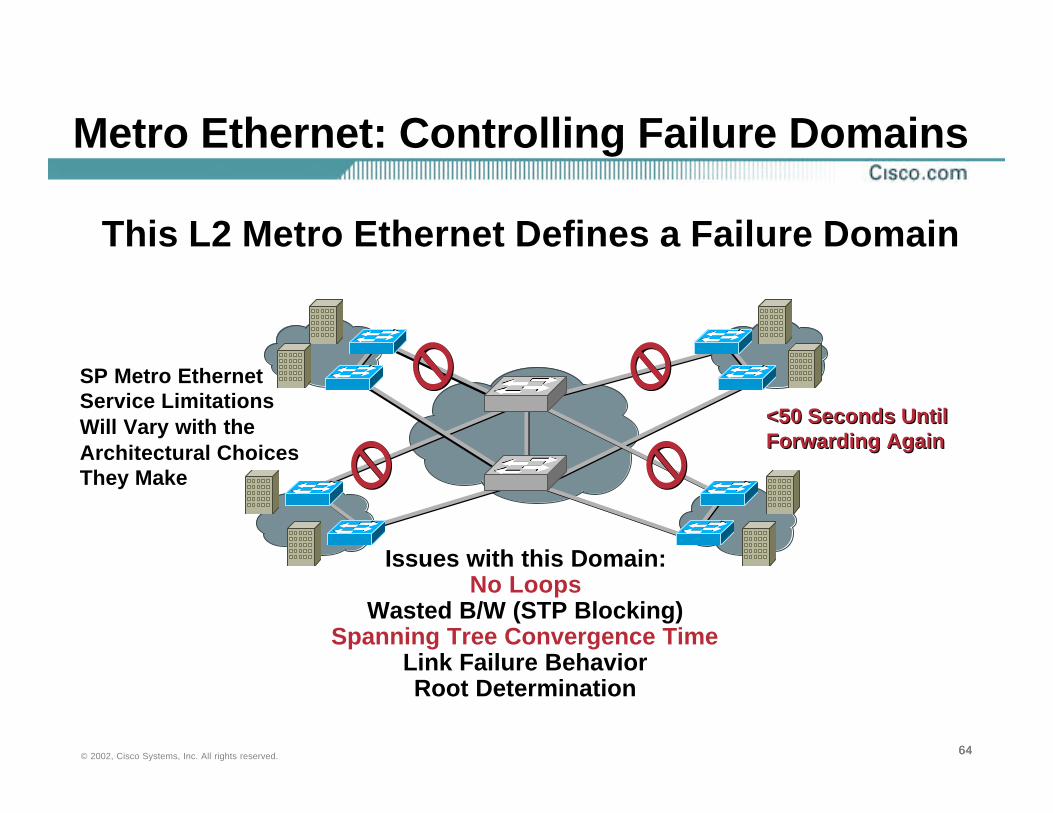
SP Metro Ethernet Service Limitations Will Vary with the Architectural Choices They Make
Metro Ethernet: Controlling Failure Domains
Issues with this Domain:No Loops
Wasted B/W (STP Blocking)Spanning Tree Convergence Time
Link Failure BehaviorRoot Determination
This L2 Metro Ethernet Defines a Failure Domain
<50 Seconds Until Forwarding Again<50 Seconds Until Forwarding Again
656565© 2002, Cisco Systems, Inc. All rights reserved.
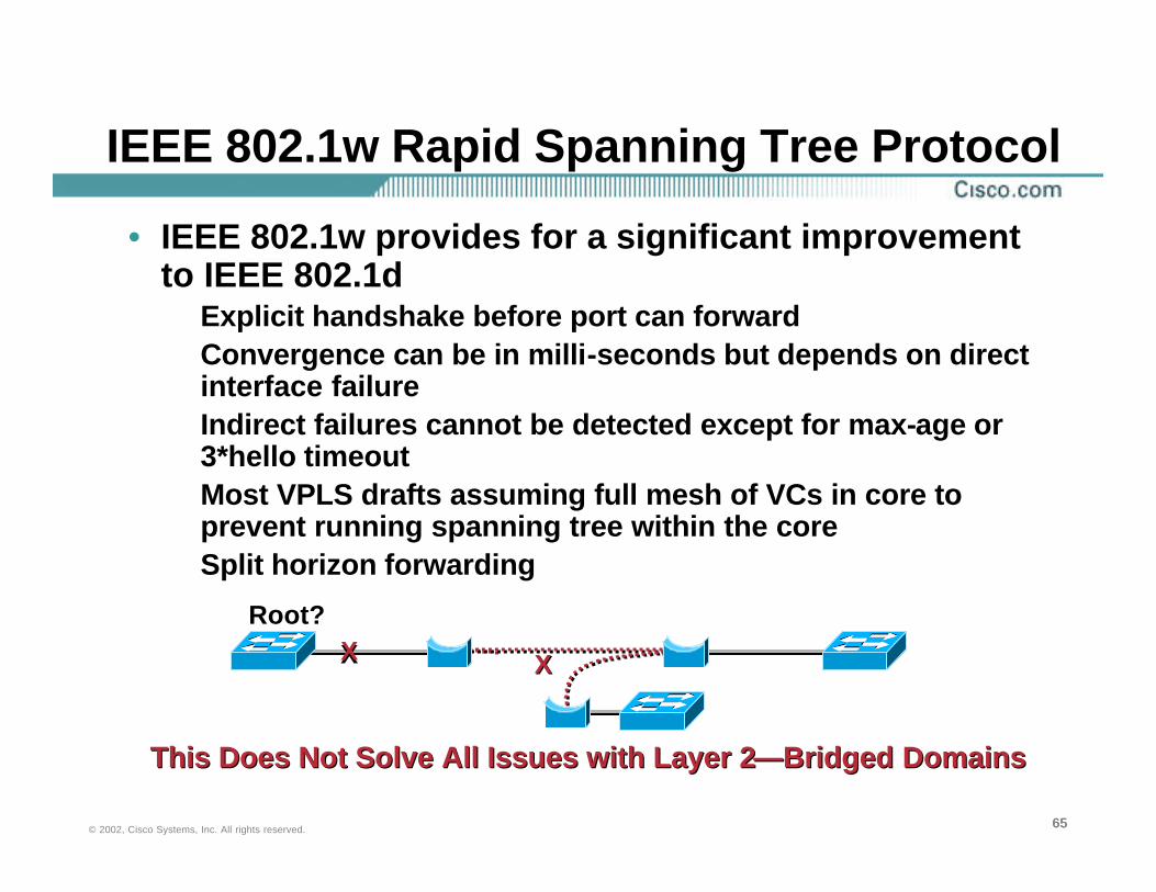
IEEE 802.1w Rapid Spanning Tree Protocol
• IEEE 802.1w provides for a significant improvement to IEEE 802.1d
Explicit handshake before port can forward Convergence can be in milli-seconds but depends on direct interface failureIndirect failures cannot be detected except for max-age or 3*hello timeout Most VPLS drafts assuming full mesh of VCs in core to prevent running spanning tree within the coreSplit horizon forwarding
This Does Not Solve All Issues with Layer 2—Bridged DomainsThis Does Not Solve All Issues with Layer 2—Bridged Domains
Root?XX XX
666666© 2002, Cisco Systems, Inc. All rights reserved.
Metro Ethernet: Spanning Tree
• Ethernet has no explicit end-to-end signaling
Max-age or 3*BPDU hellos may have to expire to detect failure.
Slow convergence even using 802.1w
Relies upon 3*keepalive loss
Dependant upon providers core for convergence characteristics
Ethernet LMI currently being defined

676767© 2002, Cisco Systems, Inc. All rights reserved.
Failure Domains: Broadcast and Multicast Radiation
A Flat Metro Ethernet Service
SP Metro Ethernet Service Limitations Will Vary with the Architectural Choices They Make
Issues with This Domain:Broadcast FloodingMulticast Flooding

686868© 2002, Cisco Systems, Inc. All rights reserved.
Metro Ethernet Service
Network Modeled as Point-to-Point LinksControlled Routing Protocol Adjacencies, Easily Defined QoS
Parameters, Simplified Troubleshooting
Network Modeled as Point-to-Point LinksControlled Routing Protocol Adjacencies, Easily Defined QoS
Parameters, Simplified Troubleshooting
How Do We Solve These Issues? Use Routing
696969© 2002, Cisco Systems, Inc. All rights reserved.
Deploying Metro Ethernet in the Enterprise
• Metro Services Evolution
• Designing with Fiber
• Designing with 10 Gigabit Ethernet
• Ethernet TLS
• Design Principles
• Metro Ethernet Design Recommendations
• Cisco Metro Solutions
Agenda
707070© 2002, Cisco Systems, Inc. All rights reserved.
Design Principles
• When designing a network several factorsPerformanceScalabilityReliability and availabilityCost efficiencySecurity
• …Need to be considered irrespective of technology to support critical business objectives, i.e. the applications

717171© 2002, Cisco Systems, Inc. All rights reserved.
Design Principles: Hierarchy
• To design a network with the correct attributes hierarchy is used to define functional blocks…
AccessDistribution Core
• …Which provide the “right” fault isolation, scaling, security, QoS and scaling characteristics

727272© 2002, Cisco Systems, Inc. All rights reserved.
Each Layer Provides Unique Functionality
Service Provider WAN
Core Layer Provides Optimal Transport Between Core and Distribution
Distribution Layer Provides Policy-Based Connectivity, Peer Reduction and Aggregation
Access Layer Provides Common Group Access to the Internetworking Environment
737373© 2002, Cisco Systems, Inc. All rights reserved.
Attributes of Modularity
• Designing and building networks in modules that are then plugged together to build a large hierarchical network provides several benefits:
Ease of growth
Allows component scaling
Streamlined training
Distributed management
Fault isolation—troubleshooting
The “Building Block” ApproachThe “Building Block” Approach

747474© 2002, Cisco Systems, Inc. All rights reserved.
Structure and Hierarchy: Summary
• Routed hierarchies enable…
Scalable network architectures
Improved application performance
Managed change
Improve service
Simplified management and troubleshooting
Reduced cost of ownership

757575© 2002, Cisco Systems, Inc. All rights reserved.
Structure and Hierarchy: Scalable Routing
• Hierarchy enables us to…Control the impact of failures
Manage change
Enable effective, deterministic routing behavior
Define fault, QoS, security, domains
Reduces the routing protocol processing overhead
Hierarchical (modular) topologies must be used with protocols such as OSPF, IS-IS or EIGRP

767676© 2002, Cisco Systems, Inc. All rights reserved.
Deploying Metro Ethernet in the Enterprise
• Metro Services Evolution
• Designing with Fiber
• Designing with 10 Gigabit Ethernet
• Ethernet TLS
• Design Principles
• Metro Ethernet Design Recommendations
• Cisco Metro Solutions
Agenda

777777© 2002, Cisco Systems, Inc. All rights reserved.
Metro Ethernet Distribution Hub and Spoke vs. EMS
• Hub and spokePredictable traffic patterns
Simple QoS and security policy definition
Simple IGP peering
Simple IP multicast behaviour
Simple troubleshooting
• Emulated LANUnpredictable traffic patternsComplex QoS and security policy definitionComplex IGP peeringComplex IP multicast behaviourComplex troubleshooting

787878© 2002, Cisco Systems, Inc. All rights reserved.
Metro Ethernet: EMS Decision Criteria
• An Ethernet Multipoint service may be considered, if…
A small number of sites are considered
Limited number of devices/hosts
Multicast is not a big requirement
• Use ERS service if these criteria cannot be metDesign for the future
Easier to implement as point-to-point than migrate later
• Layer 3 service
797979© 2002, Cisco Systems, Inc. All rights reserved.
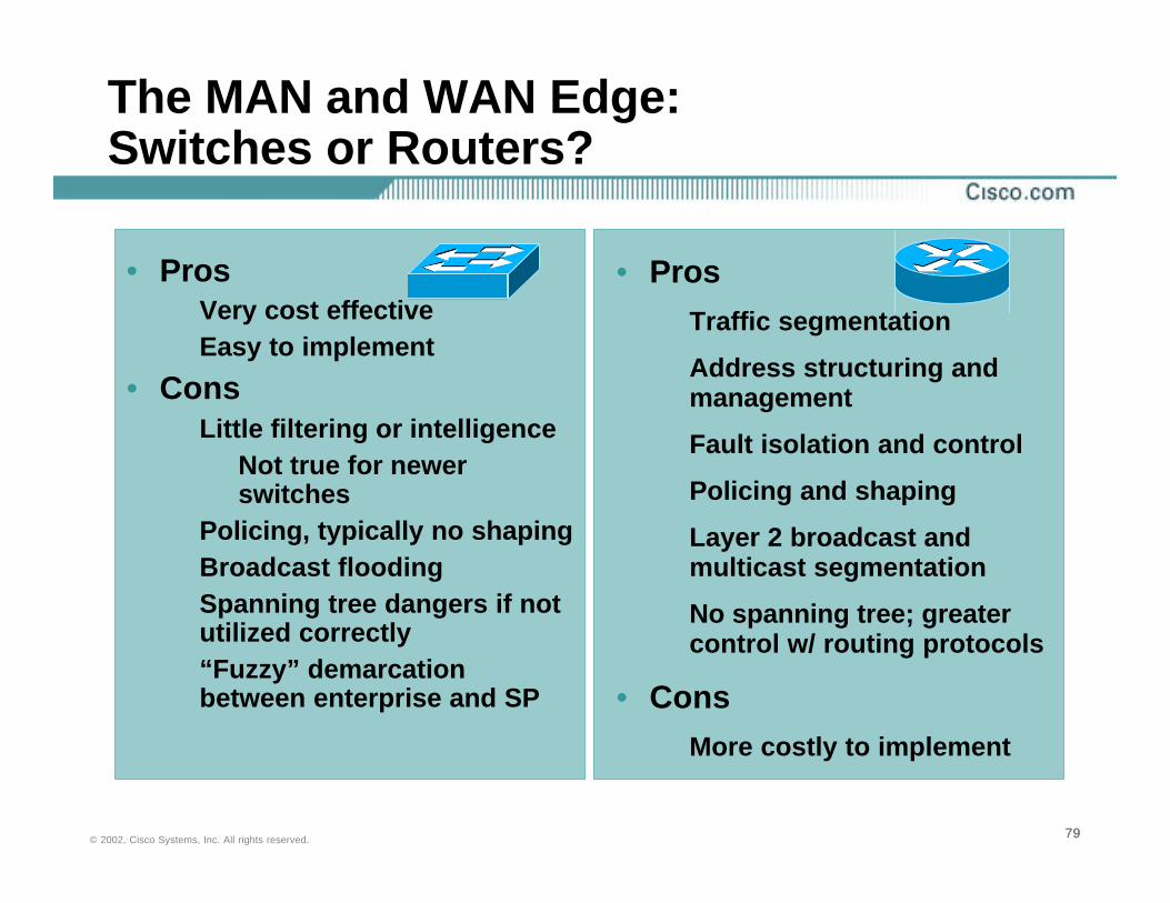
The MAN and WAN Edge: Switches or Routers?
• ProsVery cost effectiveEasy to implement
• ConsLittle filtering or intelligence
Not true for newer switches
Policing, typically no shapingBroadcast floodingSpanning tree dangers if not utilized correctly“Fuzzy” demarcation between enterprise and SP
• ProsTraffic segmentation
Address structuring and management
Fault isolation and control
Policing and shaping
Layer 2 broadcast and multicast segmentation
No spanning tree; greater control w/ routing protocols
• ConsMore costly to implement
808080© 2002, Cisco Systems, Inc. All rights reserved.
Metro Ethernet: Switched Edge Recommendations
• Suitable for data only servicesIP telephony/interactive applications need careful consideration
• Suitable for very small, simple applications~2–10 sites, ~10–20 hosts per site
• Use broadcast suppressionSet to low% of committed rate
• Use intelligent switches and police using VACLsto define QoS policies
Note: traffic shaping is not typically supported

818181© 2002, Cisco Systems, Inc. All rights reserved.
Metro Ethernet: Switched Edge Recommendations
• From a security perspective…Configure port security internally
Consider IEEE 802.1x
There should only be one MAC address per port
Disable VTP on edge switches
Could be used as a denial of service attack
Disable CDP on edge ports
Advertises device, IP and software versions
Could be used as a DOS attack
Disable DTP on edge switches
Define only the VLANs that you require for connectivity
Configure spanning tree ROOT guard
828282© 2002, Cisco Systems, Inc. All rights reserved.
Metro Ethernet: Why Routers?
• Sophisticated traffic managementLLQ, CBQ, CAR, etc.
• Sophisticated security managementACLs, firewall features, etc.
• Structured address managementIP addresses
• Simplified policy managementQoS, security, etc.
• Simple fault determination and convergenceExplicit one-to-one relationshipsRobust routing protocol support

838383© 2002, Cisco Systems, Inc. All rights reserved.
Metro Ethernet: Distribution Hub and Spoke
• Deploy metro Ethernet as virtual leased linesDeploy routers as the edge device of choice
Enables key features such as IP multicast routing, content services, security, etc.
Model links as frame relay or ATM PVCs
Use VLANs as sub interfaces
Use VLAN tags like DLCI or PVCs
Apply same QoS and security policies as existing Frame Relay networks
848484© 2002, Cisco Systems, Inc. All rights reserved.
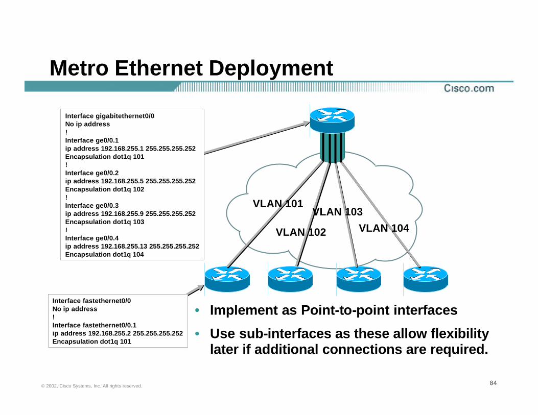
Metro Ethernet Deployment
• Implement as Point-to-point interfaces
• Use sub-interfaces as these allow flexibility later if additional connections are required.
VLAN 101
VLAN 102
VLAN 103
VLAN 104
Interface gigabitethernet0/0No ip address!Interface ge0/0.1ip address 192.168.255.1 255.255.255.252Encapsulation dot1q 101!Interface ge0/0.2ip address 192.168.255.5 255.255.255.252Encapsulation dot1q 102!Interface ge0/0.3ip address 192.168.255.9 255.255.255.252Encapsulation dot1q 103!Interface ge0/0.4ip address 192.168.255.13 255.255.255.252Encapsulation dot1q 104
Interface fastethernet0/0No ip address!Interface fastethernet0/0.1ip address 192.168.255.2 255.255.255.252Encapsulation dot1q 101
858585© 2002, Cisco Systems, Inc. All rights reserved.
Metro Edge: Why Routers? Policing and Shaping?
• Shaping is required to allow flexibility in the way bandwidth is managed
• Policing is a “hard” limit, congestion unaware mechanism
Within contract yes/no decision
• Metro Ethernet will be a sub-rate serviceI.e. 10Mbps within a 100Mbps connectionProvider will police your traffic
• Shaper ensures that congestion is notified on interface even if there is no actual congestion
“Virtual” queue

868686© 2002, Cisco Systems, Inc. All rights reserved.
Metro Edge: Why Routers? Policing and Shaping?
• An exampleAssume that we have a 100Mbps connection and a 20Mbps access rate
4Mbps allocated for IP voice
6Mbps allocated for video traffic
6Mbps allocated for business critical traffic
4Mbps allocated for everything else
• But, in the absence of higher or lower priority traffic, I want to be a able to burst into those classes
• Solution: Combine police and shaping

878787© 2002, Cisco Systems, Inc. All rights reserved.
Metro Edge: Why Routers? Policing and Shaping?• “Optical” configuration
policy-map customer_classesclass VOICE
police 4000000 conform-action set-prec-transmit 5 exceed-action droppriority 4000
class MISSION-CRITICALbandwidth 20000
service-policy customer_classes bandwidth 6000police 6000000 conform-action set-prec-transmit 3 exceed-action set-
prec-transmit 0class VIDEObandwidth 6000police 6000000 conform-action set-prec-transmit 2 exceed-action set-
prec-transmit 0class BEST-EFFORTbandwidth 4000
police 4000000 conform-action set-prec-transmit 0 exceed-action set-prec-transmit 0policy-map shape_outputclass ALL-CUSTOMER-CLASSESshape average 20000000
!
888888© 2002, Cisco Systems, Inc. All rights reserved.
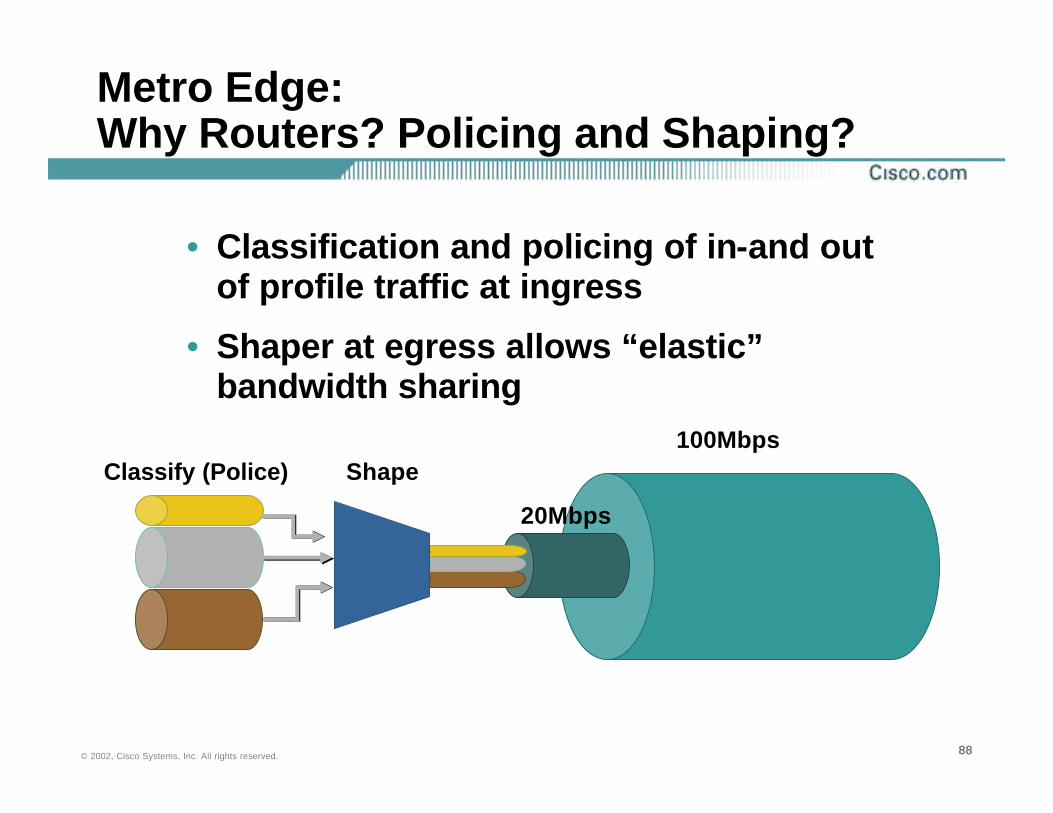
Metro Edge: Why Routers? Policing and Shaping?
• Classification and policing of in-and out of profile traffic at ingress
• Shaper at egress allows “elastic” bandwidth sharing
Classify (Police) Shape100Mbps
20Mbps

898989© 2002, Cisco Systems, Inc. All rights reserved.
Metro Ethernet: ERS Recommendation
• Point-to-point ERS service modelled as existing Frame Relay or ATM deployments today
Optimum scaling characteristics
Optimum QoS policy
Optimum security policy
Optimum troubleshooting and management
• Leverages existing expertiseWell understood and widely deployed model in Frame Relay and ATM networks today

909090© 2002, Cisco Systems, Inc. All rights reserved.
Metro Ethernet ERS: Network Design Practice
• Improved performance
Support for deterministic traffic engineering designs for routing protocols
Deterministic convergence
Traffic load share on equal cost paths
Minimize downtime: By providing redundancy and alternative path routing where appropriate
919191© 2002, Cisco Systems, Inc. All rights reserved.
Metro Ethernet ERS: Good Network Design Practice
• Improved managementEase change: Building block approach, plus well-defined boundaries
Minimize downtime: By provided redundancy and alternative path routing
Maximize services: QoS, rate limiting, voice, etc…implemented at appropriate levels of the network
Distribute the security policy and processing load by creating well-defined functional layers
929292© 2002, Cisco Systems, Inc. All rights reserved.
Deploying Metro Ethernet in the Enterprise
• Metro Services Evolution
• Designing with Fiber
• Designing with 10 Gigabit Ethernet
• Ethernet TLS
• Design Principles
• Metro Ethernet Design Recommendations
• Cisco Metro Solutions
Agenda

939393© 2002, Cisco Systems, Inc. All rights reserved.
Cisco Metro Fusion
• Comprehensive service portfolio meeting diverse application requirements
• Deliver efficient and flexible design options and architectures
• Proven industry leadership delivering unparalleled network scale and service availability
• Driving industry innovation: architectures, technologies, standards
OpticalTransport
OpticalOpticalTransportTransport
EthernetSwitchingEthernet
SwitchingIPIP
Metro FusionMetro Fusion
94© 2002, Cisco Systems, Inc. All rights reserved.
Deploying Metro Ethernet Solutions

95© 2002, Cisco Systems, Inc. All rights reserved.
Please Complete Your Evaluation Form
Session – Deploying Metro Ethernet Solutions

969696© 2002, Cisco Systems, Inc. All rights reserved.