
Deploying Industrial Firewalls within a Converged...
113
Deploying Industrial Firewalls within a Converged Plantwide Ethernet Architecture Design and Implementation Guide December 2016 Document Reference Number: ENET-TD002A-EN-P
-
Upload
nguyenhanh -
Category
Documents
-
view
236 -
download
1
Transcript of Deploying Industrial Firewalls within a Converged...

Deploying Industrial Firewalls within a Converged Plantwide Ethernet Architecture
Design and Implementation Guide
December 2016
Document Reference Number: ENET-TD002A-EN-P

Preface
Converged Plantwide Ethernet (CPwE) is a collection of tested and validated architectures that are developed by subject matter authorities at Cisco and Rockwell Automation and that follow the Cisco Validated Design (CVD) program. The content of CPwE, which is relevant to both Operational Technology (OT) and Informational Technology (IT) disciplines, consists of documented architectures, best practices, guidance and configuration settings to help manufacturers with design and deployment of a scalable, reliable, secure and future-ready plant-wide industrial network infrastructure. CPwE also helps manufacturers achieve the benefits of cost reductions using proven designs that can help lead to quicker deployment and reduced risk in deploying new technology.
The Deploying Industrial Firewalls within a Converged Plantwide Ethernet Architecture Design and Implementation Guide (DIG) outlines several use cases for designing, deploying and managing industrial firewalls throughout a plant-wide Industrial Automation and Control System (IACS) network infrastructure. This DIG highlights the key IACS application requirements, technology, and supporting design considerations to help with the successful design and deployment of these specific use cases within the framework of CPwE.
Document OrganizationThis document is composed of the following chapters and appendices.
Chapter/Appendix Description
CPwE Industrial Firewalls Overview Provides an overview of CPwE Industrial Firewalls, including Holistic Industrial Security and Industrial Firewalls Use Cases.
CPwE Industrial Firewalls Design Considerations
Provides an overview of design considerations for integrating the CPwE Industrial Firewalls into an IACS network based on the CPwE architecture.
CPwE Industrial Firewalls Configuration
Describes how to configure the CPwE Industrial Firewalls within the CPwE architecture based on the design considerations and recommendations of the previous chapter.
CPwE Industrial Firewalls Troubleshooting
Describes how to assess and verify the status of the CPwE Industrial Firewalls.
References References that are relevant to the CPwE Industrial Firewalls solution.
Test Hardware and Software Lists the test hardware and software for the CPwE Industrial Firewalls solution.
CIP Preprocessor Glossary Provides definitions of CIP General Applications and CIP Rockwell Automation (Vendor Specific) Applications.
Glossary Lists the acronyms and initialisms used in this document.
About the Cisco Validated Design (CVD) Program
Describes the purpose of and steps for the Cisco Validated Design (CVD) process.
iiDeploying Industrial Firewalls within a Converged Plantwide Ethernet Architecture
ENET-TD002A-EN-P

PrefaceFor More Information
For More InformationMore information on CPwE Design and Implementation Guides can be found at the following URLs:
• Rockwell Automation site:
– http://www.rockwellautomation.com/global/products-technologies/network-technology/architectures.page?
• Cisco site:
– http://www.cisco.com/c/en/us/solutions/enterprise/design-zone-manufacturing/landing_ettf.html
Note This release of the CPwE architecture focuses on EtherNet/IP™, which utilizes the ODVA Common Industrial Protocol (CIP™), and is ready for the Industrial Internet of Things (IIoT). For more information on EtherNet/IP, see odva.org at the following URL:
• http://www.odva.org/Technology-Standards/EtherNet-IP/Overview
iiiDeploying Industrial Firewalls within a Converged Plantwide Ethernet Architecture
ENET-TD002A-EN-P

PrefaceFor More Information
ivDeploying Industrial Firewalls within a Converged Plantwide Ethernet Architecture
ENET-TD002A-EN-P

Deploying Industrial Firewalls within a Con
ENET-TD002A-EN-P
C H A P T E R 1
CPwE Industrial Firewalls OverviewThis chapter includes the following major topics:
• Holistic Industrial Security, page 1-2
• Industrial Firewalls Use Cases, page 1-3
The prevailing trend in IACS networking is the convergence of IACS OT with IT technology. CPwE helps to enable network technology convergence using standard Ethernet and Internet Protocol (IP) technology, which helps to enable the IIoT.
By default, a converged IACS network is generally open. Openness facilitates both technology coexistence and IACS device interoperability, which helps to enable the choice of best-in-class IACS products. This openness also requires that configuration and architecture secure and harden IACS networks. The degree of hardening depends upon the required security stance. Business practices, corporate standards, security policies, application requirements, industry security standards, regulatory compliance, risk management policies and overall tolerance to risk are key factors in determining the appropriate security stance.
Plant-wide deployment of Industrial Firewalls (IFW), which is part of a holistic defense-in-depth industrial security stance, helps to harden the IACS network infrastructure and creates smaller zones of trust. Industrial firewalls have the ability to restrict and inspect traffic flow throughout the plant-wide IACS network. It is common for OT personnel to apply industrial firewalls to protect their legacy IACS applications - equipment, machines or skids. It is becoming more common for Original Equipment Manufacturers (OEMs) to include an industrial firewall as part of their offering. To support this convergence of OT and IT, modern industrial firewalls support the capability of being deployed and managed using several different methodologies that are either locally or centrally managed. Locally managed is common for OT plant personnel and OEM applications. Centrally managed is common for IT.
Deploying Industrial Firewalls within a Converged Plantwide Ethernet Architecture CVD, which is documented in this DIG, outlines several use cases for designing, deploying and managing industrial firewalls throughout a plant-wide IACS network. The CPwE Industrial Firewalls CVD is brought to market through a strategic alliance between Cisco Systems and Rockwell Automation.
CPwE is the underlying architecture that provides standard network services for control and information disciplines, devices and equipment found in modern IACS applications. The CPwE architectures (Figure 1-1), through testing and validation by Cisco and Rockwell Automation, provide design and implementation guidance, test results and documented configuration settings that can help to achieve the real-time communication, reliability, scalability, security and resiliency requirements of modern IACS applications.
1-1verged Plantwide Ethernet Architecture

Chapter 1 CPwE Industrial Firewalls OverviewHolistic Industrial Security
Figure 1-1 CPwE Architectures
Holistic Industrial SecurityNo single product, technology or methodology can fully secure IACS applications. Protecting IACS assets requires a defense-in-depth security approach, which addresses internal and external security threats. This approach uses multiple layers of defense (administrative, technical, and physical) at separate IACS levels that address different types of threats. The CPwE Industrial Network Security Framework (Figure 1-2), which uses a defense-in-depth approach, is aligned to industrial security standards such as IEC-62443 (formerly ISA-99) IACS Security and NIST 800-82 Industrial Control System (ICS) Security.
Designing and implementing a comprehensive IACS network security framework should serve as a natural extension to the IACS application. Network security should not be implemented as an afterthought. The industrial network security framework should be pervasive and core to the IACS. However, for existing IACS deployments, the same defense-in-depth layers can be applied incrementally to help improve the security stance of the IACS.
CPwE defense-in-depth layers (Figure 1-2) include:
• Control System Engineers (highlighted in tan)—IACS device hardening (for example, physical and electronic), infrastructure device hardening (for example, port security), network segmentation (trust zoning), industrial firewalls (with inspection) at the IACS application edge, IACS application authentication, authorization and accounting (AAA)
1-2Deploying Industrial Firewalls within a Converged Plantwide Ethernet Architecture
ENET-TD002A-EN-P

Chapter 1 CPwE Industrial Firewalls OverviewIndustrial Firewalls Use Cases
• Control System Engineers in collaboration with IT Network Engineers (highlighted in blue)—computer hardening (OS patching, application white listing), network device hardening (for example, access control, resiliency), wireless LAN access policies
• IT Security Architects in collaboration with Control Systems Engineers (highlighted in purple)—Identity Services (wired and wireless), Active Directory (AD), Remote Access Servers, plant firewalls, Industrial Demilitarized Zone (IDMZ) design best practices
Figure 1-2 CPwE Industrial Network Security Framework
Industrial Firewalls Use CasesAn IACS is deployed in a wide variety of discrete and process manufacturing industries such as automotive, pharmaceuticals, consumer packaged goods, pulp and paper, oil and gas, mining and energy. IACS applications are made up of multiple control and information disciplines such as continuous process, batch, discrete and hybrid combinations. One of the challenges facing manufacturers is the industrial hardening of standard Ethernet and IP-converged IACS networking technologies to take advantage of the business benefits associated with the IIoT.
This Deploying Industrial Firewalls within a CPwE Architecture DIG outlines the concepts, requirements and technology solutions for application use cases that were tested, validated and documented by Cisco and Rockwell Automation to help support a hardened and converged plant-wide EtherNet/IP IACS architecture. The following is a summary of the CPwE IFW CVD use cases:
• Industrial Firewalls Technology Overview
– Modes of operation
– Inline Transparent mode
– Inline Routed mode
Port Security
Physical
Electronic
IACS Device Hardening
Policies and Procedures
Physical Measures
Electronic Measures
Encrypted Communications
MCC
Enterprise Zone: Levels 4-5
Soft Starter
I/O
Physical or Virtualized Servers• Patch Management• AV Server• Application Mirror• Remote Desktop Gateway Server
Level 0 - ProcessLevel 1 - Controller
Level 3 – Site Operations
Controller
Drive
Level 2 – Area Supervisory Control
FactoryTalkClient
Controller
Industrial Demilitarized Zone (IDMZ)
Industrial Zone: Levels 0-3Authentication, Authorization and Accounting (AAA)
LWAP
SSID2.4 GHz
SSID5 GHz GB
I/O
I/O
I/O
Active
Wireless LAN Controller (WLC)
Standby
CoreSwitches
DistributionSwitch Stack
Enterprise
Identity Services
External DMZ/ Firewall
Internet
IES IES
IES
IESIES
DAPWAPIT Security Architects in
Collaboration with Control
Systems Engineers
Control System Engineers
in Collaboration with IT
Network Engineers
(Industrial IT)
Control System Engineers
Active Directory (AD)
Identity Services Engine (ISE)
FactoryTalk Security
Remote Access Server (RAS)
OS Hardening
Application Hardening
VLANs, Segmenting
Domains of Trust
Industrial
Firewall
Network Infrastructure
Hardening
Access Control
Resiliency
Network Status
and Monitoring
Plant Firewalls
Active/Standby
Inter-zone traffic segmentation
ACLs, IPS and IDS
VPN Services
Portal and Remote Desktop Services proxy
Standard DMZ Design BEST Practices
Wireless LAN (WLAN)
Access Policy
Equipment SSID
Plant Personnel SSID
Trusted Partners SSID
WPA2 with AES Encryption
Autonomous WLAN
Pre-Shared Key
802.1X - (EAP-FAST)
Unified WLAN
802.1X - (EAP-TLS)
CAPWAP DTLS
37
65
89
FireSIGHT Management Center
Cisco Security Manager
IFW
1-3Deploying Industrial Firewalls within a Converged Plantwide Ethernet Architecture
ENET-TD002A-EN-P

Chapter 1 CPwE Industrial Firewalls OverviewIndustrial Firewalls Use Cases
– Passive Monitor-only mode
– Network Protection (Cisco Adaptive Security Appliance)
– Intrusion Prevention and Detection (Cisco FireSIGHT® Management System), Deep Packet Inspection (DPI) of the Common Industrial Protocol (CIP)
– Industrial Firewalls (IFW)
– Allen-Bradley® Stratix® 5950 Industrial Network Security Appliance
– The Cisco Industrial Security Appliance 3000
• Application use cases (Figure 1-3)
– Equipment/Machine/Skid Protection
– Cell/Area Zone Protection
– Redundant Star Topology, Ring Topology
– Cell/Area Zone Monitoring
• Management Use Cases
– Local Management
– Command Line Interface (CLI), Adaptive Security Device Manager
– Centralized Management
– Cisco FireSIGHT Management Center, Cisco Security Manager
• Migration from local to centralized management of industrial firewalls
Figure 1-3 Plant-wide Industrial Firewalls Deployments
DistributionSwitch
HMI
Soft Starter
Drive
IES
IESIES
IES
Cell/Area Zones - Levels 0 - 2Ring Topology, Redundant Star Topology
(Lines, Machines, Skids, Equipment)
IESIES
IESIES
IESMachine
IESIES
IESSkid
IESIES
IESSkid IESIES
IESEquipment
Industrial ZoneLevels 0 - 3
(Plant-wide Network)
Transparent Mode
IndustrialEthernetSwitch
Controller
IndustrialDemilitarized Zone
(IDMZ)
FireSIGHT Management CenterCisco Security Manager
Monitor Mode
Transparent Mode
Transparent Mode Transparent
Mode
CoreSwitches
Transparent Mode
IFW
IFW
IFW
IFW
IFW
IFW
IFW
37
65
87
1-4Deploying Industrial Firewalls within a Converged Plantwide Ethernet Architecture
ENET-TD002A-EN-P

Chapter 1 CPwE Industrial Firewalls OverviewIndustrial Firewalls Use Cases
Note This document references FireSIGHT Management Center as the centralized management software for the IFW FirePOWER™ modules. Starting with version 6.0, the software was renamed Firepower Management Center. Either version is capable of managing IFW FirePOWER modules that are performing CIP inspection. For more information on this terminology change, please see the Cisco Firepower Compatibility Guide at the following URL:
• http://www.cisco.com/c/en/us/td/docs/security/firepower/compatibility/firepower-compatibility.html
1-5Deploying Industrial Firewalls within a Converged Plantwide Ethernet Architecture
ENET-TD002A-EN-P

Deploying Industrial Firewalls within a Con
ENET-TD002A-EN-P
C H A P T E R 2
CPwE Industrial Firewalls Design ConsiderationsThis chapter, which provides an overview of design considerations for integrating the IFW into an IACS network based on the CPwE architecture, includes the following major topics:
• Security Policy Considerations, page 2-1
• Industrial Firewalls Technologies Overview, page 2-3
• Industrial Firewalls Deployment Considerations, page 2-18
• Industrial Firewalls Use Cases, page 2-23
Security Policy ConsiderationsThe majority of companies understand the need for security and, therefore, have policies governing enterprise systems such as the Internet or email use. It is, however, common that security policies are often insufficient or, in some cases, nonexistent in Industrial Zone systems.
A security policy is a general statement produced by management or a security board to dictate security governance as it relates to organizational policy, an issue-specific policy or a system-specific policy. Policies are written in simple and easy-to-understand language that describes the purpose of the policy and defines who must follow the policy and the system(s) involved with the policy. Because policies are written in very general manner, they are typically supported with procedures, standards and guidelines to provide the detail on how the policy will be implemented, enforced and monitored. Companies will commonly create security policies and then focus on the technologies that enforce the policies, whether they are technical controls such as a firewall or a non-technical controls such as a procedure.
A firewall policy is a system-specific policy that describes how the firewall will handle application traffic such as web, email or telnet. A firewall policy should describe who will manage the firewall, how the firewall is to be managed and how the firewall will be updated.
Risk Analysis
Before a firewall policy is created, the organization should perform some form of risk analysis that is based on the organization's security stance and that results in a list of the traffic types needed by the organization. Those traffic types should then be categorized as to how they must be secured-including which types of traffic
2-1verged Plantwide Ethernet Architecture

Chapter 2 CPwE Industrial Firewalls Design ConsiderationsSecurity Policy Considerations
can traverse a firewall under what circumstances. This risk analysis should be based on an evaluation of threats, vulnerabilities and countermeasures in place to mitigate vulnerabilities and the impact if IACS applications or data are compromised. Firewall policy should be documented in the IACS application security plan and maintained and updated frequently as classes of new attacks or vulnerabilities arise, or as the organization's needs regarding network applications change. The policy should also include specific guidance on how to address changes to the ruleset.
Note More information regarding risk analysis can be found in the Guidelines on Firewalls and Firewall Policy at the following URL:
• http://csrc.nist.gov/publications/nistpubs/800-41-Rev1/sp800-41-rev1.pdf
Firewall Policy Considerations
To improve the effectiveness and security of their firewalls, organizations should follow these recommendations:
Create a firewall policy that specifies how firewalls should handle inbound and outbound network traffic.
A firewall policy defines how an organization's firewalls should handle inbound and outbound network traffic for specific IP addresses and address ranges, protocols, applications and content types based on the organization's information security policies. Organizations should conduct risk analysis to develop a list of the types of traffic needed by the organization and how they must be secured-including which types of traffic can traverse a firewall under what circumstances. Generally, all inbound and outbound traffic not expressly permitted by the firewall policy should be blocked because such traffic is not needed by the IACS application or the greater organization. This practice helps reduce the risk of attack and can also decrease the volume of traffic carried on the organization's IACS networks.
Identify all requirements that should be considered when determining which firewall to implement.
Organizations should evaluate many considerations in their firewall selection and planning processes. They need to determine which IACS network areas need to be protected, and which types of firewall technologies will be most effective for the types of traffic that require protection. Several important performance considerations and concerns regarding the integration of the firewall into existing IACS network and security infrastructures also exist. Also, firewall solution design involves requirements relating to physical environment and personnel and consideration of possible future needs, such as plans to adopt new IPv6 technologies or Virtual Private Networks (VPNs).
Create rulesets that implement the organization's firewall policy while supporting firewall performance.
Firewall rulesets should be as specific as possible in regard to the IACS network traffic they control. Creating a ruleset involves determining required traffic types, including protocols the firewall may need to use for management purposes. The details of creating rulesets vary widely by firewall type and specific products, but many firewalls can get improved performance by optimizing firewall rulesets. For example, some firewalls check traffic against rules in a sequential manner until a match is found; for these firewalls, rules that have the highest chance of matching traffic patterns should be placed at the top of the list wherever possible.
Manage firewall architectures, policies, software and other components throughout the life of the firewall solutions.
Firewall management is complicated. For example, the type or types of deployed firewalls and their positions within the network can significantly affect the security policies that the firewalls enforce. When new applications or hosts are implemented within the network, the organization's requirements may change and
2-2Deploying Industrial Firewalls within a Converged Plantwide Ethernet Architecture
ENET-TD002A-EN-P

Chapter 2 CPwE Industrial Firewalls Design ConsiderationsIndustrial Firewalls Technologies Overview
the policy rules may need to be updated. Firewall performance also needs to be monitored to help identify and address potential resource issues before components become overwhelmed. Logs and alerts should also be continuously monitored to identify anomalous behavior-both successful and unsuccessful. Because of a firewall's potential to affect security and business operations, rulesets and policies should be managed by a formal change management process, with ruleset reviews or tests performed periodically to validate continued compliance with the organization's policies. Firewall software should be patched as vendors provide updates to address vulnerabilities.
Note More information regarding the creation of firewall policies can be found in Guidelines on Firewalls and Firewall Policy at the following URL:
• http://csrc.nist.gov/publications/nistpubs/800-41-Rev1/sp800-41-rev1.pdf
Industrial Firewalls Technologies Overview
Industrial Firewalls (IFW)
Overview
The Industrial Firewall (Cisco Industrial Security Appliance 3000 and Allen-Bradley Stratix 5950), or IFW, is an appliance that provides OT-targeted protection based on proven enterprise class security. The IFW is ideal for IACS applications where trusted zone segmentation is required. It provides the anchor point for converging IT and OT security visibility without interfering with industrial operational practice. Manufacturers can improve security and gain visibility with the IFW's ability to track OT application behavior for industrial protocols such as CIP and abnormal traffic patterns and malicious attacks.
The IFW currently has two form factor variations:
• 4x10/100/1000Base-T plus a dedicated management port
• 2x1GbE SFP and 2x10/100/1000Base-T plus a dedicated management port
The IFW incorporates the same security as the Cisco Adaptive Security Appliance with FirePOWER Services software, while providing the following benefits to introduce additional security within IACS networks:
• Operates in harsh environments with a DIN rail-mountable ruggedized design.
• Provides access, threat, and application controls for demanding industrial environments.
• Provides common security processes and network security management across IT and OT systems. This combination allows companies to use their existing IT security expertise while meeting OT-specific needs.
• Simplifies compliance since increasing internal, industry, and government regulations places burdens on industrial operators. The IFW helps deliver consistent policy enforcement and the segmentation (trusted zoning) needed to simplify compliance and reduce audit scope.
• Mitigates risk: Enables connectivity without compromising IACS application availability. The IFW provides application awareness and understanding of protocols such as CIP and rich OT-specific threat detection. This helps to increase visibility across the IT and OT environments, enables consistent policy enforcement and minimizes risks to system availability.
2-3Deploying Industrial Firewalls within a Converged Plantwide Ethernet Architecture
ENET-TD002A-EN-P

Chapter 2 CPwE Industrial Firewalls Design ConsiderationsIndustrial Firewalls Technologies Overview
Key features of the IFW platform include:
• Resilience—Endures temperatures from -40° C to 70° C (Cisco Industrial Security Appliance 3000) or 60°C (Allen-Bradley Stratix 5950), vibration, shock, surge, electrical noise and dual DC power inputs
• Compliance—Conforms to specifications for industrial automation environments
• Durability—Fanless, convection-cooled design with no moving parts
• Ease of Use—Multiple IFW can be managed by a centralized software platform
• Authentication—Provides user-specific access and control
• Threat Detection—Tracks more than 25,000 rules to provide application-specific protection
• Visibility and Control—Monitors industrial applications and protocols
Note For more general information on the IFW platform, see the following URLs:
• Stratix 5950 Security Appliance page at: http://ab.rockwellautomation.com/Networks-and-Communications/Stratix-5950-Security-Appliance
• Cisco Industrial Security Appliance 3000 page at: http://www.cisco.com/c/en/us/support/security/industrial-security-appliance-3000/model.html
Logical Framework
Figure 2-1 provides a logical overview of the IFW, which has two components: the Adaptive Security Appliance (ASA) and FirePOWER module.
• The ASA provides the firewall functionality that can permit or deny traffic based on configured rules.
• The FirePOWER module has the ability to perform application specific protocol analysis for DPI.
The IFW can be managed through either a local Adaptive Security Device Manager (ASDM) or a centralized management server.
Figure 2-1 IFW Logical Architecture
2-4Deploying Industrial Firewalls within a Converged Plantwide Ethernet Architecture
ENET-TD002A-EN-P
Chapter 2 CPwE Industrial Firewalls Design ConsiderationsIndustrial Firewalls Technologies Overview
Hardware Bypass
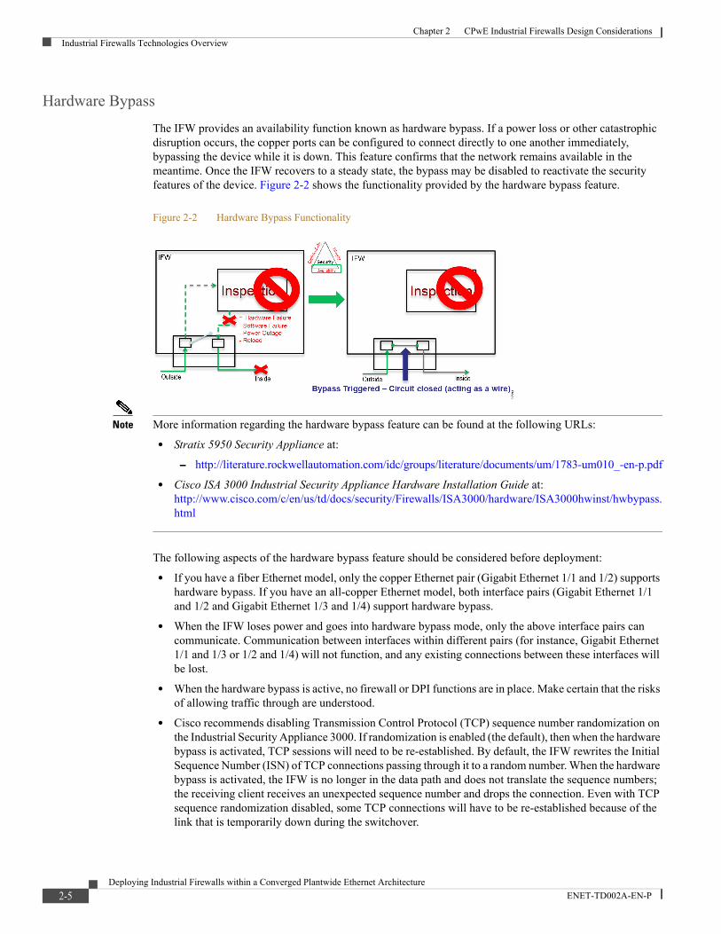
The IFW provides an availability function known as hardware bypass. If a power loss or other catastrophic disruption occurs, the copper ports can be configured to connect directly to one another immediately, bypassing the device while it is down. This feature confirms that the network remains available in the meantime. Once the IFW recovers to a steady state, the bypass may be disabled to reactivate the security features of the device. Figure 2-2 shows the functionality provided by the hardware bypass feature.
Figure 2-2 Hardware Bypass Functionality
Note More information regarding the hardware bypass feature can be found at the following URLs:
• Stratix 5950 Security Appliance at:
– http://literature.rockwellautomation.com/idc/groups/literature/documents/um/1783-um010_-en-p.pdf
• Cisco ISA 3000 Industrial Security Appliance Hardware Installation Guide at: http://www.cisco.com/c/en/us/td/docs/security/Firewalls/ISA3000/hardware/ISA3000hwinst/hwbypass.html
The following aspects of the hardware bypass feature should be considered before deployment:
• If you have a fiber Ethernet model, only the copper Ethernet pair (Gigabit Ethernet 1/1 and 1/2) supports hardware bypass. If you have an all-copper Ethernet model, both interface pairs (Gigabit Ethernet 1/1 and 1/2 and Gigabit Ethernet 1/3 and 1/4) support hardware bypass.
• When the IFW loses power and goes into hardware bypass mode, only the above interface pairs can communicate. Communication between interfaces within different pairs (for instance, Gigabit Ethernet 1/1 and 1/3 or 1/2 and 1/4) will not function, and any existing connections between these interfaces will be lost.
• When the hardware bypass is active, no firewall or DPI functions are in place. Make certain that the risks of allowing traffic through are understood.
• Cisco recommends disabling Transmission Control Protocol (TCP) sequence number randomization on the Industrial Security Appliance 3000. If randomization is enabled (the default), then when the hardware bypass is activated, TCP sessions will need to be re-established. By default, the IFW rewrites the Initial Sequence Number (ISN) of TCP connections passing through it to a random number. When the hardware bypass is activated, the IFW is no longer in the data path and does not translate the sequence numbers; the receiving client receives an unexpected sequence number and drops the connection. Even with TCP sequence randomization disabled, some TCP connections will have to be re-established because of the link that is temporarily down during the switchover.
2-5Deploying Industrial Firewalls within a Converged Plantwide Ethernet Architecture
ENET-TD002A-EN-P

Chapter 2 CPwE Industrial Firewalls Design ConsiderationsIndustrial Firewalls Technologies Overview
Note TCP sequence number randomization is typically enabled to help prevent attackers from being able to guess the sequence numbers, which allows them to inject false data or prematurely close the connection. Therefore, the benefits of disabling this feature mentioned above must be weighed with the security risk that is introduced. The Stratix 5950 already has TCP sequence number randomization disabled by default, so no changes are necessary.
• When the hardware bypass is deactivated and traffic resumes going through the IFW data path, some existing TCP sessions will need to re-establish themselves because of the link that is temporarily down during the switchover.
• Hardware bypass is not supported in all scenarios. For instance, hardware bypass cannot be used when the IFW is located inline with a trunk link carrying Virtual Local Area Network (VLAN)-tagged traffic. In addition, hardware bypass can only be used when the IFW is in inline transparent mode.
Note Please see Industrial Firewalls Use Cases, page 2-23 for more details about which scenarios support hardware bypass.
Network Protection (Adaptive Security Appliance)
Firewalls are traditionally used to separate networks with differing security requirements (security zones), such as the Enterprise Zone and the Industrial Zone. One of the primary functions of a firewall is to inhibit unauthorized traffic from entering or exiting a security zone. To support this key functionality, firewalls are typically placed at the entrance or exit points of the security zone. Firewalls are known as boundary or edge security appliances because they define the boundary or the edge of a security zone. Figure 2-3 shows a high-level view of how an IACS network might be segmented into security (trusted) zones using industrial firewalls.
2-6Deploying Industrial Firewalls within a Converged Plantwide Ethernet Architecture
ENET-TD002A-EN-P

Chapter 2 CPwE Industrial Firewalls Design ConsiderationsIndustrial Firewalls Technologies Overview
Figure 2-3 Security (Trusted) Zones with Firewall Segmentation
Organizations have used firewalls as a means to control ingress and egress traffic from external untrusted networks to internal networks or systems. For example, organizations use firewalls to construct an External Demilitarized Zone (DMZ) to provide Internet ingress and egress traffic inspection. These firewalls are placed at the edge of a security zone and help provide protection for Enterprise servers that communicate with the Internet.
Firewalls have also been placed between internal networks where security requirements are different between security zones. For example, the Enterprise Zone is often within a security zone distinct from the Industrial Zone. It is a recommended practice to architect an Industrial Demilitarized Zone (IDMZ) between these two security zones. The IDMZ is implemented using firewalls to define the security boundaries between the Enterprise and Industrial security zones.
Note For more information on the IDMZ, please see the Securely Traversing IACS Data Across the Industrial Demilitarized Zone (IDMZ) DIG found at the following URLs:
• Rockwell Automation site at: http://literature.rockwellautomation.com/idc/groups/literature/documents/td/enet-td009_-en-p.pdf
• Cisco site at: http://www.cisco.com/c/en/us/td/docs/solutions/Verticals/CPwE/3-5-1/IDMZ/DIG/CPwE_IDMZ_CVD.html
Firewalls are normally positioned either as a node where the network splits into multiple paths, or inline with a single network path. In routed networks, the firewall usually resides at the location immediately before traffic enters the router. The vast majority of firewalls are capable of providing routing and in some network designs, the firewall will act as both the firewall and the router.
Most firewalls are capable of inspecting the following elements of a packet:
• Source MAC or IP Address
Cell/Area Zone - Levels 0-2 Cell/Area Zone - Levels 0-2
IndustrialDemilitarized Zone
(IDMZ)
Enterprise ZoneLevels 4-5
Industrial ZoneLevels 0-3
(Plant-wide Network)
Cell/Area Zone - Levels 0-2
Enterprise
Level 3 - Site Operations(Control Room)
Internet
IES IES
IESIES
IES IES
IES
IES IES
IES
IES IES
Security Zone
Security Zone
Security Zone
Security Zone
Security Zone
Security Zone
Security Zone
Security Zone
Security ZoneIES
Active/Standby Firewalls
IES IES
IFW IFWIFW IFW IFW IFW
IFW
37
72
44
2-7Deploying Industrial Firewalls within a Converged Plantwide Ethernet Architecture
ENET-TD002A-EN-P

Chapter 2 CPwE Industrial Firewalls Design ConsiderationsIndustrial Firewalls Technologies Overview
• Destination MAC or IP Address
• Source TCP or UDP Port
• Destination TCP or UDP Port
• Protocol - Layer 2, 3, 4 or 7
These are commonly known as five-tuple firewalls. Typically, firewall rules will include these five elements to configure a rule. The firewall will be configured to permit or deny ingress and egress traffic based on these five-tuple rules.
A firewall may inspect traffic for conformance with proper protocol behavior and drop non-compliant traffic, but the firewall will not have deep knowledge of the protocol. To inspect and make permit and deny decisions at the protocol level, DPI capabilities are needed, and these are discussed in the following section.
Intrusion Prevention and Detection (FirePOWER)
DPI provides the ability to inspect the packet past the basic header information at the protocol level. DPI determines the contents of a particular packet, and then either records that information for statistical purposes or performs an action on the packet such as permit or discard. DPI is a capability used by Intrusion Detection (IDS) and Intrusion Prevention (IPS). IPS and IDS relate to what is to be done after the packet has been inspected by DPI.
As mentioned in the previous section, the firewall's primary function is to permit or deny traffic between networks based on configured rules. Some firewalls may inspect traffic for conformance with proper protocol behavior and drop non-compliant traffic, but DPI functionality is required to interpret beyond the basic protocol behavior. Protocol interpretation is added to the DPI module so that an administrator can configure DPI rules to monitor, log and permit or deny packets as they relate to the protocol.
IPS inspects traffic flowing through a network and is capable of blocking or otherwise remediating flows that it determines are malicious. Usually IPS devices are placed inline with the traffic so that the traffic can be blocked before entering or exiting the network or before it reaches the end hosts.
IDS is similar to IPS, but does not affect flows in any way. IDS only logs or alerts on malicious traffic based on the DPI rules.
CIP Preprocessor Overview
In addition to the Network Analysis Policy rules engine that is called a preprocessor, the IFW FirePOWER module has a software component. The preprocessor is responsible for handling the interpretation of the packet before being handled by the rules engine. The IFW has a CIP preprocessor that is capable of interpreting the CIP protocol, which allows the system administrator to author policy rules related to the CIP protocol actions.
CIP is an open protocol that encompasses a comprehensive suite of objects and services for industrial automation applications. CIP is used to communicate between ControlLogix® Programmable Automation Controller (PAC) processors and I/O subsystems for discrete control, process control, safety, motion control, real time information and network management. The IFW with the CIP preprocessor has the ability to inspect a packet that contains the CIP protocol and determine whether to permit or deny the traffic based on the preconfigured policy rules.
Two types of CIP DPI rule categories have been added to the IFW:
• CIP Generic—Related to the open CIP standard
• Rockwell Automation (vendor) specific CIP—CIP protocol extensions specific to Rockwell Automation products
2-8Deploying Industrial Firewalls within a Converged Plantwide Ethernet Architecture
ENET-TD002A-EN-P

Chapter 2 CPwE Industrial Firewalls Design ConsiderationsIndustrial Firewalls Technologies Overview
CIP Generic Categories
The CIP protocol has a generic set of commands that are defined by the CIP open standards. The IFW has the ability to define security policies as they relate to the CIP open standard. The list of supported CIP generic categories and the respective applications are listed in Table 2-1.
In Table 2-1, CIP Read is the Category that is comprised of the CIP Read and CIP Infrastructure applications. Some categories are comprised of multiple applications to achieve the category function.
See Appendix C, “CIP Preprocessor Glossary,” for detailed descriptions of the individual Available Applications for each category.
CIP Rockwell Automation (Vendor Specific) Extension Categories
It is common for a standard to be extended by a vendor to support the vendor-specific requirements not covered in the open standard. These are often proprietary extensions, which is why additional preprocessors are required for vendor-specific protocol extensions.
The CIP generic or open standard rules have been extended by Rockwell Automation to support Rockwell Automation devices. The Rockwell Automation CIP extensions that have been added to the IFW are listed in Table 2-2.
See Appendix C, “CIP Preprocessor Glossary,” for detailed descriptions of the individual Available Applications for each category.
Table 2-1 CIP Generic Category Definition
Categories Description Application(s) Usage
CIP Admin ODVA-specified commands that change the state of a device
CIP Admin Block tools or commands to reset or change the state of a generic CIP device
CIP Read ODVA-specified commands that read data from a device
CIP Infrastructure
CIP Read
Block tools or commands that read generic CIP data from a device
CIP Write ODVA-specified commands that write data into a device
CIP Write Block tools or commands that write generic CIP data to a device
Table 2-2 CIP Rockwell Automation Extension Category Definitions
Categories Description Application(s) Usage
CIP RA Admin Rockwell Automation-specified commands that change the state of a device
CIP Admin
CIP RA Admin Download
CIP RA Admin Firmware Update
CIP RA Admin Other
Block ControlFlash or any tool that flashes Rockwell Automation Firmware
Blocks Rockwell Automation Logix Designer from Downloading programs
Using RSLinx to change a module's Networking properties, such as: IP address, Netmask, Gateway, DNS server, Domain name, Hostname, Speed, Duplex Mode, Interface Speed
Using any tool to reset a device
CIP RA Read Rockwell Automation-specified commands that read data from a device
CIP Infrastructure
CIP Read
CIP RA Infrastructure
CIP RA Read Tag
CIP Read Tag Other
Any general read action.
Example: RSLinx®
browsing, HMI reading a tag
CIP Write Rockwell Automation-specified commands that write data into a device
CIP Write
CIP RA Write Tag
CIP RA Write Tag Other
Block tools or commands that sets values via CIP. Example: HMI setting a tag value, RSLinx changing various properties of a device (properties that don't fall under CIP RA Admin)
2-9Deploying Industrial Firewalls within a Converged Plantwide Ethernet Architecture
ENET-TD002A-EN-P

Chapter 2 CPwE Industrial Firewalls Design ConsiderationsIndustrial Firewalls Technologies Overview
Adding CIP Generic and Rockwell Automation (Vendor Specific) CIP Extension Rules
The IFW FirePOWER software denotes CIP Generic rules within the Application Categories as CIP while Rockwell Automation vendor-specific CIP extensions are denoted as CIP RA, as shown in Figure 2-4.
Figure 2-4 IFW FirePOWER CIP Application Filters
Some of the Categories, such as CIP Read, once selected contain multiple Available Applications, as seen in the middle column of Figure 2-5.
Figure 2-5 IFW FirePOWER CIP Available Applications
The CIP and CIP RA Categories that require multiple applications have been preconfigured to include all of the proper applications (as shown in Figure 2-5). When creating rules, choose the Category in the left most column and then choose Figure 2-6. Choose the Category (as shown in Figure 2-6)—do not choose individual Available Applications in the middle column to create the rule.
Once a CIP rule is added, you will see a Categories: listed in the Selected Application and Filters in the right most area of Figure 2-6.
2-10Deploying Industrial Firewalls within a Converged Plantwide Ethernet Architecture
ENET-TD002A-EN-P
Chapter 2 CPwE Industrial Firewalls Design ConsiderationsIndustrial Firewalls Technologies Overview
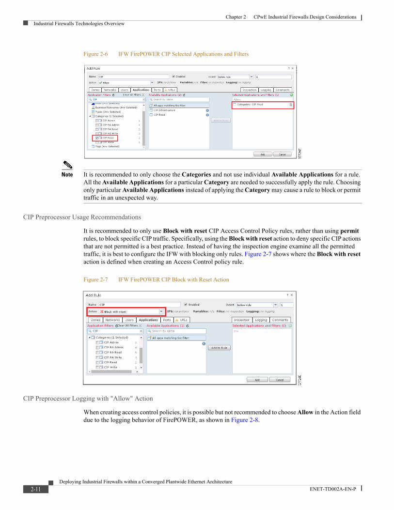
Figure 2-6 IFW FirePOWER CIP Selected Applications and Filters
Note It is recommended to only choose the Categories and not use individual Available Applications for a rule. All the Available Applications for a particular Category are needed to successfully apply the rule. Choosing only particular Available Applications instead of applying the Category may cause a rule to block or permit traffic in an unexpected way.
CIP Preprocessor Usage Recommendations
It is recommended to only use Block with reset CIP Access Control Policy rules, rather than using permit rules, to block specific CIP traffic. Specifically, using the Block with reset action to deny specific CIP actions that are not permitted is a best practice. Instead of having the inspection engine examine all the permitted traffic, it is best to configure the IFW with blocking only rules. Figure 2-7 shows where the Block with reset action is defined when creating an Access Control policy rule.
Figure 2-7 IFW FirePOWER CIP Block with Reset Action
CIP Preprocessor Logging with "Allow" Action
When creating access control policies, it is possible but not recommended to choose Allow in the Action field due to the logging behavior of FirePOWER, as shown in Figure 2-8.
2-11Deploying Industrial Firewalls within a Converged Plantwide Ethernet Architecture
ENET-TD002A-EN-P

Chapter 2 CPwE Industrial Firewalls Design ConsiderationsIndustrial Firewalls Technologies Overview
Figure 2-8 IFW FirePOWER CIP Allow Action
The logging behavior is such that an Allow selection will log the first packet that matches the rule, but will not log subsequent packets that match the rule. Therefore, it is recommended to use Block with reset when creating access control policy rules.
CIP Preprocessor Granularity
The CIP protocol does not include user information within the packet so, therefore, CIP security policies cannot be written to block a specific user. CIP security policies can be written to include host network or host addresses, but IACS application security such as FactoryTalk Security can be used to enforce specific user or groups permitted or denied actions.
OpenAppID Rules
The CIP Generic and CIP Rockwell Automation preprocessor categories were added to the IFW FirePOWER module using the OpenAppID functionality. OpenAppID allows users and vendors to add their own protocol detectors to identify traffic that isn't natively supported by the IFW FirePOWER module. Rockwell Automation used the capabilities of OpenAppID to add CIP protocol visibility that enables the implementer the ability to construct CIP access control policies. The CIP Generic and CIP Rockwell Automation preprocessor capabilities are not available as open source and are not distributable.
IPS Rules
In addition to using OpenAppID rules to create access control policies, intrusion policies can be used within the policy. Intrusion Policies are defined sets of intrusion detection and prevention configurations that inspect traffic for security violations and, in inline deployments, can block or alter malicious traffic. Intrusion policies are invoked by your access control policy and are the system's last line of defense before traffic is allowed to its destination.
Intrusion polices can be created using the IFW FirePOWER Intrusion Policy rule editor; however, the intent of creating access control policies is to use the preconfigured OpenAppID applications.
Note For a complete list of CIP Intrusion Policies, see the Stratix 5950 User Manual (1783-UM010A-EN-P) at the following URL:
• http://literature.rockwellautomation.com/idc/groups/literature/documents/um/1783-um010_-en-p.pdf
2-12Deploying Industrial Firewalls within a Converged Plantwide Ethernet Architecture
ENET-TD002A-EN-P

Chapter 2 CPwE Industrial Firewalls Design ConsiderationsIndustrial Firewalls Technologies Overview
Industrial Firewalls Management
The IFW can be managed through either the local ASDM or a centralized management platform; these options, along with associated recommendations, are included in this section.
Local Management (ASDM)
The IFW can be managed locally using the Adaptive Security Device Manager (ASDM), a simple GUI-based management application. ASDM is used to configure, manage, and troubleshoot both the ASA and FirePOWER components of the IFW. The IFW comes preloaded with the ASDM software, which is accessible via the Management interface (by default).
ASDM provides the following functions:
• Setup wizards that help you configure and manage ASA devices
• Powerful real-time log viewer and monitoring dashboards that provide an at-a-glance view of ASA appliance status and health
• Troubleshooting features and powerful debugging tools such as packet trace and packet capture
Figure 2-8 shows the tools available within the ASDM interface.
Figure 2-9 ASDM Interface Overview
Note More information regarding ASDM can be found on the Cisco Adaptive Security Device Manager page at the following URL:
• http://www.cisco.com/c/en/us/products/security/adaptive-security-device-manager/index.html
The IFW's dedicated management port is assigned a default static IP address. To connect to ASDM, a client PC is connected to the management port and its browser is pointed to that address.
Dynamic Host Configuration Protocol (DHCP)-enabled clients that are connected to the management port may obtain an IP address directly from the IFW. The default configuration provides a DHCP server that is enabled on the management port. The range of IP addresses that can be leased to the DHCP clients are in a range that does not overlap the IP address assigned to the management port.
Note For more details on how to connect to the IFW and use ASDM, see CPwE Industrial Firewalls Configuration.
2-13Deploying Industrial Firewalls within a Converged Plantwide Ethernet Architecture
ENET-TD002A-EN-P

Chapter 2 CPwE Industrial Firewalls Design ConsiderationsIndustrial Firewalls Technologies Overview
Centralized Management
Local management can get cumbersome when we need to manage many IFWs in the IACS network. A centralized management helps enable consistent policy enforcement and quick troubleshooting of security events, offering summarized reports across the security deployment. A centralized interface helps organizations to scale efficiently and manage a wide range of security devices with improved visibility.
As explained in earlier sections, the IFW has two components: the ASA and FirePOWER module. Each component is managed by a separate centralized management application. The FirePOWER component is managed by FireSIGHT Management Center, and the ASA component is managed by Cisco Security Manager (CSM). The following sections provide an overview of each application.
Note This document references FireSIGHT Management Center as the centralized management software for the IFW FirePOWER modules. Starting with version 6.0, the software was renamed as Firepower Management Center. Either version is capable of managing IFW FirePOWER modules that are performing CIP inspection. For more information on this terminology change, please see the Cisco Firepower Compatibility Guide at the following URL:
• http://www.cisco.com/c/en/us/td/docs/security/firepower/compatibility/firepower-compatibility.html
FireSIGHT Management Center
The Cisco FireSIGHT Management Center manages the FirePOWER module of the IFW. FireSIGHT Management Center is the administrative nerve center for a number of security products that incorporate FirePOWER technology. It provides complete and unified management of application control, intrusion prevention, URL filtering, and advanced malware protection. The Management Center is the centralized point for event and policy management for the IFW platform.
The FireSIGHT Management Center provides extensive intelligence about the users, applications, devices, threats, and vulnerabilities that exist in your network. It also uses this information to analyze your network's vulnerabilities and provides tailored recommendations on what security policies to put in place and what security events you should investigate. Figure 2-10 shows examples of the types of data that can be gathered using FireSIGHT Management Center.
Figure 2-10 FireSIGHT Management Center Overview
2-14Deploying Industrial Firewalls within a Converged Plantwide Ethernet Architecture
ENET-TD002A-EN-P

Chapter 2 CPwE Industrial Firewalls Design ConsiderationsIndustrial Firewalls Technologies Overview
The FireSIGHT Management Center discovers real-time information about changing network resources and operations to provide a full contextual basis for making informed decisions. In addition to providing a wide breadth of intelligence, the FireSIGHT Management Center delivers a fine level of detail, including:
• Trends and high-level statistics that help managers and executives understand their security posture at a given moment in time as well as how it's changing, for better or worse
• Event detail, compliance and forensics that provide an understanding of what happened during a security event to improve defenses, support breach containment efforts and aid in legal enforcement actions
• Workflow data that can be easily exported to other solutions to improve incident response management
Note More information on the FireSIGHT Management Center can be found in the Cisco Firepower Management Center Data Sheet at the following URL:
• http://www.cisco.com/c/en/us/products/collateral/security/firesight-management-center/datasheet-c78-736775.html
Cisco Security Manager
The Cisco Security Manager (CSM) provides scalable, centralized management for the ASA component of the IFW. Using CSM, administrators can gain visibility and maintain policy compliance across the network. Designed for operational efficiency, CSM also includes a powerful suite of automated capabilities, such as health and performance monitoring, software image management, automatic conflict detection and integration with ticketing systems. Figure 2-11 shows an overview of CSM.
Figure 2-11 Cisco Security Manager Overview
CSM provides the following functions:
• Policy and object management:
– Helps enable reuse of security rules and objects
2-15Deploying Industrial Firewalls within a Converged Plantwide Ethernet Architecture
ENET-TD002A-EN-P

Chapter 2 CPwE Industrial Firewalls Design ConsiderationsIndustrial Firewalls Technologies Overview
– Facilitates process compliance and error-free deployments
– Improves ability to monitor security threats
• Event management:
– Supports syslog messages created by Cisco security devices
– Facilitates viewing of real-time and historical events
– Provides rapid navigation from events to source policies
– Includes pre-bundled and customizable views for firewall, intelligent protection switching (intrusion prevention systems) and VPN
• Reporting and troubleshooting:
– Provides system and custom reports
– Offers export and scheduled email delivery of reports in CSV or PDF format
– Provides advanced troubleshooting with tools such as ping, traceroute, and packet tracer
• Image management:
– Provides direct, simplified upgrade of ASA software images using an intuitive wizard
– Offers scheduling of image upgrade jobs during network maintenance windows
– Imports images from the Cisco online software website or from a local file system
– Provides automated updates that can be performed on each ASA individually or run in groups
• Health and Performance Monitoring (HPM):
– Adds visibility around health and performance of ASAs, IPSs and VPNs.
– Offers ability to set thresholds on various parameters
– Provides alerts when predefined thresholds are reached
• Application Program Interface (API) access:
– Shares information with other essential network services such as compliance and advanced security analysis systems
– Provides direct access to data from any security device managed by Cisco Security Manager using external firewall compliance systems
– Is compatible with various security compliance vendors such as Tufin, Algosec and Skybox
• Other functionalities
– Provides insight into Talos Security Intelligence and Research Group (Talos) recommendations
– Helps administrators fine-tune their environments before deploying signature updates
Note More information on the Cisco Security Manager can be found on the Cisco Security Manager page at the following URL:
• http://www.cisco.com/c/en/us/products/security/security-manager/index.html
2-16Deploying Industrial Firewalls within a Converged Plantwide Ethernet Architecture
ENET-TD002A-EN-P

Chapter 2 CPwE Industrial Firewalls Design ConsiderationsIndustrial Firewalls Technologies Overview
Management Recommendations
The following aspects of managing the IFW should be considered before deployment:
• Local management using ASDM is recommended for small deployments only (no more than five IFW devices).
• When managing the IFW locally using ASDM, the real-time event log for the FirePOWER module will only display the 100 most recent events. Therefore, this logging feature cannot be used to characterize flagged traffic over a longer period of time. The events should be configured to be sent to a syslog or SNMP server if long-term characterization is desired.
• Centralized management is recommended for most deployments due to ease of manageability, policy consistency, quick troubleshooting, scalability and robust logging capabilities.
• Cisco and Rockwell Automation recommend positioning the centralized management server in Level 3 Site Operations within the Industrial Zone.
• When the FirePOWER module of the IFW is being managed by the FireSIGHT Management Center, local (ASDM) configuration of the FirePOWER module is not supported.
• FireSIGHT Management Center and Cisco Security Manager generally support communication with the IFW via its dedicated management interface only.
• Where it is feasible for centralized management, having an out-of-band management network is recommended to provide direct connectivity between the management port of the IFW and the server. Otherwise, the IFW management port will need to be connected back into the network at a suitable point to provide reachability.
Note More information on best practices around creating an out-of-band management network can be found in the Cisco SAFE Reference Guide at the following URL:
• http://www.cisco.com/c/en/us/td/docs/solutions/Enterprise/Security/SAFE_RG/SAFE_rg/chap9.html
Integration of New Industrial Firewalls
The following tasks are required to migrate a locally managed IFW to a centralized management system (more details on this process are provided in CPwE Industrial Firewalls Configuration):
1. In ASDM, configure the FireSIGHT Management Center as a remote manager.
2. Change the management IP addresses for both the ASA and FirePOWER module to unique IP addresses within the management network.
3. Connect the dedicated management interface to the management network.
4. Add required licenses within FireSIGHT Management Center.
Note Licenses used on a locally managed IFW can be migrated to FireSIGHT Management Center by logging into http://www.cisco.com/go/licensing and selecting Rehost/Transfer.
5. Add the IFW in the centralized management application (FirePOWER and/or Cisco Security Manager).
2-17Deploying Industrial Firewalls within a Converged Plantwide Ethernet Architecture
ENET-TD002A-EN-P

Chapter 2 CPwE Industrial Firewalls Design ConsiderationsIndustrial Firewalls Deployment Considerations
Note Locally configured FirePOWER policies will be lost when migrating from local management to FireSIGHT Management Center. Confirm that the current policies are exported and backed up, if needed, before migrating the device.
Industrial Firewalls Deployment ConsiderationsThe IFW can be deployed in a variety of modes, depending on the level of desired policy enforcement and risk tolerance. When placed in inline mode, the IFW is inserted into the network segment, enabling it to monitor traffic and enforce both firewall and inspection policies. When placed in passive mode, the IFW is separate from the network segment, so it can only monitor traffic.
Three variations of these modes can be enabled on the IFW:
• Inline transparent mode
• Inline routed mode
• Passive (monitor-only) mode
The following sections provide details and considerations for each supported deployment mode of the IFW.
Inline Transparent Mode
The IFW operates in inline transparent mode by default. In inline transparent mode, the IFW acts like a bump in the wire, and is not considered a router hop (connects to the same network on its inside and outside interfaces). Two variations of this deployment can exist, as described:
• Inline Transparent Mode—In this mode, traffic is evaluated against ASA firewall policies, such as access rules, and any traffic that is flagged for blocking by these policies is dropped. A subset of the traffic is then evaluated against FirePOWER inspection policies, and any traffic that is flagged for blocking by these policies is dropped.
• Inline Transparent Monitor-only Mode—In this mode, traffic is evaluated against ASA firewall policies, such as access rules, and any traffic that is flagged for blocking by these policies is dropped. A subset of the traffic is then evaluated against FirePOWER inspection policies, but the result of this evaluation is not enforced. Rather, the IFW only indicates what action it would have taken based on the outcome of the evaluation, had it not been set to monitor-only.
Note You cannot configure both inline transparent monitor-only mode and inline transparent mode at the same time on the ASA. Only one type of security policy is allowed.
Inline Transparent Mode
In inline transparent mode, traffic goes through the ASA firewall checks before being forwarded to the FirePOWER module. The module blocks traffic that is not allowed for a certain application. All other traffic is forwarded through the ASA. Figure 2-12 shows the traffic flow when using the IFW in inline transparent mode.
2-18Deploying Industrial Firewalls within a Converged Plantwide Ethernet Architecture
ENET-TD002A-EN-P

Chapter 2 CPwE Industrial Firewalls Design ConsiderationsIndustrial Firewalls Deployment Considerations
Figure 2-12 IFW Traffic Flow for Inline Transparent Mode
As shown in Figure 2-12, traffic flows through the IFW as follows:
1. Traffic enters the IFW.
2. ASA firewall policies are applied.
3. Traffic is sent to the FirePOWER module.
4. The FirePOWER module applies its security policy to the traffic, and takes appropriate actions.
5. Valid traffic is sent back to the ASA; the FirePOWER module might block some traffic according to its security policy.
6. Traffic exits the IFW.
Inline Transparent Monitor-only Mode
Inline transparent monitor-only mode sends a duplicate stream of traffic to the IFW FirePOWER module for monitoring purposes only. The module applies the security policy to the traffic and logs what it would have done if it were operating in inline transparent mode; for example, traffic might be marked would have dropped in events. You can use this information for traffic analysis and to help you decide if inline transparent mode is desirable. Figure 2-13 shows the traffic flow when using the IFW in inline transparent monitor-only mode.
Figure 2-13 IFW Traffic Flow for Inline Transparent Monitor-only Mode
As shown in Figure 2-13, traffic flows through the IFW as follows:
1. Traffic enters the IFW.
2-19Deploying Industrial Firewalls within a Converged Plantwide Ethernet Architecture
ENET-TD002A-EN-P

Chapter 2 CPwE Industrial Firewalls Design ConsiderationsIndustrial Firewalls Deployment Considerations
2. ASA firewall policies are applied.
3. Copied traffic is sent to the FirePOWER module.
4. The FirePOWER module applies its security policy to the traffic and logs events only.
5. Traffic exits the IFW.
Inline Transparent Mode Performance
Generally, when placed between the edge of the Cell/Area Zone and in front of an OEM application (equipment/skid/machine), the IFW should not negatively affect the traffic being transmitted through it for the use cases that were tested and validated as part of this DIG. However, it is important to assess the network loads and latency requirements for the IACS applications that will be communicating across the IFW before placing the device inline in the network. The IFW can sustain throughput in the range of 10 to 170 Mbps (13,000 to 186,000 packets per second) and may introduce additional latency in the range of 0.17 to 23 ms, depending on several factors including:
• Traffic type: CIP Class 1 (implicit) or Class 3 (explicit)
• Whether the IFW has the CIP inspection features enabled or not
• Average packet size
Therefore, if unusually high volumes of traffic are being sent or if a particular IACS application is sensitive to increased latency, inserting the IFW could have a noticeable impact on network performance.
Inline Routed Mode
In inline routed mode, the ASA is considered to be a router hop in the network and operates at Layer 3. Each interface has IP addresses assigned, as well as other typical Layer 3 attributes. Broadcast and multicast traffic (TTL = 1) is blocked even if it is allowed in an access rule, including traffic generated by unsupported dynamic routing protocols and DHCP (unless DHCP relay is configured).
From a FirePOWER inspection perspective, inline routed mode functions identically to inline transparent mode. Traffic goes through the ASA firewall checks before being forwarded to the FirePOWER module. The module blocks traffic that is not allowed for a certain application. All other traffic is routed through the ASA. Refer back to Figure 2-12 on page 2-19 for the detailed traffic flow.
In addition, the IFW can function in inline routed monitor-only mode, where a duplicate stream of traffic is sent to the FirePOWER module for monitoring purposes only. Again, this mode functions identically to inline transparent monitor-only mode. Refer back to Figure 2-13 on page 2-19 for the detailed traffic flow.
Note Hardware bypass is not supported when the IFW is running in routed mode.
Inline Routed Mode Performance
Generally, when placed appropriately between the edge of the Cell/Area Zone and in front of an OEM application (equipment/skid/machine), the IFW should not negatively affect the traffic being transmitted through it for the use cases that were tested and validated as part of this DIG. However, it is important to assess the network loads and latency requirements for the IACS applications that will be communicating across the IFW before placing the device inline in the network. If unusually high volumes of traffic are being sent, or if a particular application is unusually sensitive to increased latency, inserting the IFW could have a noticeable
2-20Deploying Industrial Firewalls within a Converged Plantwide Ethernet Architecture
ENET-TD002A-EN-P

Chapter 2 CPwE Industrial Firewalls Design ConsiderationsIndustrial Firewalls Deployment Considerations
impact on network performance. The IFW can sustain throughput in the range of 15 to 150 Mbps (15,000 to 147,000 packets per second) and may introduce additional latency in the range of 0.23 to 12.8 ms, depending on several factors including:
• Traffic type: CIP Class 1 (implicit) or Class 3 (explicit)
• Whether the IFW has the CIP inspection features enabled or not
• Average packet size
Therefore, if unusually high volumes of traffic are being sent or if a particular IACS application is sensitive to increased latency, inserting the IFW could have a noticeable impact on network performance.
Passive Monitor-only Mode
If you want to avoid any possibility of the IFW affecting traffic, you can configure a traffic-forwarding interface and connect it to a SPAN port on a switch. In this mode, all traffic is sent directly to the IFW FirePOWER module without ASA processing. The traffic is black holed, in that nothing is returned from the module and the IFW does not forward the traffic out of any of its interfaces.
In passive monitor-only mode, the module applies the security policy to the traffic and lets you know what it would have done if it were operating in inline transparent mode; for example, traffic might be marked would have dropped in events. Figure 2-14 shows the traffic flow when using the IFW in passive monitor-only mode.
Figure 2-14 IFW Traffic Flow for Passive Monitor-only Mode
As shown in Figure 2-14, traffic flows through the IFW as follows:
1. Traffic enters the IFW on the traffic-forwarding interface.
2. All traffic is sent directly to the FirePOWER module.
3. The FirePOWER module applies its security policy to the traffic and logs events only.
2-21Deploying Industrial Firewalls within a Converged Plantwide Ethernet Architecture
ENET-TD002A-EN-P

Chapter 2 CPwE Industrial Firewalls Design ConsiderationsIndustrial Firewalls Deployment Considerations
Deployment Recommendations
Placement and deployment of the IFW depends on the desired function of the device in the industrial network. Placing the IFW inline with traffic flow generally provides the ability to monitor the traffic and/or take desired actions (including blocking), while placing the IFW outside of the traffic flow only provides the ability to monitor the traffic. Please see Industrial Firewalls Use Cases, page 2-23 for recommended placements of the IFW within the IACS network.
The basic firewall capabilities of the IFW are supported in all deployment modes. In addition, the inspection capabilities of the IFW are supported when it is placed inline and configured to inspect and block desired protocols (such as CIP). However, when the IFW is configured to inspect and allow CIP, which typically creates long-term and persistent TCP connections, the IFW has limited ability to log applications running within those connections.
Most networking protocols that use TCP have short-lived connections for exchanging small amounts of data, so the FirePOWER component was designed to only log the beginning and/or end of these connections. For CIP, this means that the IFW will inspect and log the beginning of the connection, but will not log any other CIP applications that are allowed through that same connection. As a result, if the IFW is placed in monitor-only mode, very little information can be obtained from logging, since the IFW cannot flag individual applications within an open CIP connection.
Because of the boundaries mentioned above, Cisco Systems and Rockwell Automation recommend deploying the IFW inline with the network and keeping the inspection capabilities disabled until obtaining a full understanding of which CIP applications should be blocked. The ASA contains a built-in packet capture utility that can be employed to observe traffic patterns across the IFW, and the resulting PCAP file can be analyzed by standard tools such as Wireshark. Once the CIP applications to block have been identified, and the capture confirms that these blocking rules will not affect standard operations, the inspection rules can be written and applied. Using monitor-only mode in any deployment model to passively inspect CIP traffic is not recommended, since it will not provide enough information about traffic flows.
Note For more information on how to use the packet capture function of the IFW, please see the ASA Packet Captures with CLI and ASDM Configuration Example at the following URL:
• http://www.cisco.com/c/en/us/support/docs/security/asa-5500-x-series-next-generation-firewalls/118097-configure-asa-00.html
When placed inline, the IFW can be deployed in transparent or routed mode. Cisco and Rockwell Automation generally recommend deploying the IFW in transparent mode (default) unless routing functionality is needed.
In summary, the deployment recommendations for the IFW are as follows:
• Inline Transparent Mode—First, deploy the IFW inline without enabling FirePOWER, and use the built-in packet capture utility to characterize traffic patterns across the device. Once the list of application categories that should be blocked has been generated, and this list is cross-referenced with the capture data to confirm that no standard operations will be affected, enable the FirePOWER inspection functionality and apply a policy that blocks the appropriate application categories.
• Inline Routed Mode—Same as transparent mode, but deployments where routing functionality is also required.
• Passive Monitor-only Mode—Deploying the IFW in this configuration is not recommended for monitoring and logging CIP connections. The FirePOWER module's logging engine is designed to log the first packet that matches the CIP access control policy event while taking note of the particular TCP
2-22Deploying Industrial Firewalls within a Converged Plantwide Ethernet Architecture
ENET-TD002A-EN-P

Chapter 2 CPwE Industrial Firewalls Design ConsiderationsIndustrial Firewalls Use Cases
connection. Packets that match the access control policy and those that have the same TCP connection ID will not be sent to the log. For this reason, it is not recommended to use passive monitor-only mode with the CIP protocol.
Industrial Firewalls Use CasesThe IFW is used to segment (zone) networks with differing security requirements and is also strategically placed within a network to monitor and log traffic. In this section, several architectures and the use cases they are meant to address will be discussed.
Machine/Skid Protection
Overview
The machine/skid protection use case is used to segment a machine, skid or unit from the Cell/Area Zone network. This may be to support different security requirements between the larger IACS network and the machine/skid or to restrict ingress and egress traffic. In this placement, the IFW can be run in either transparent or routed mode (see the corresponding subsection for details).
Inline Transparent Mode
The inline transparent mode IFW is placed between a larger network and a grouping of IACS equipment that act as a machine, skid or unit to help protect that unit. In each case, the IFW acts as an ingress and egress point to the machine/skid where traffic can be monitored or controlled through firewall or DPI security policies. Figure 2-15 shows the placement of the IFW within the overall network architecture for this use case, as well as for the security zones created by this deployment.
2-23Deploying Industrial Firewalls within a Converged Plantwide Ethernet Architecture
ENET-TD002A-EN-P

Chapter 2 CPwE Industrial Firewalls Design ConsiderationsIndustrial Firewalls Use Cases
Figure 2-15 Industrial Firewalls Placement for Machine/Skid Protection (Inline Transparent Mode)
Inline Routed Mode
The inline routed mode IFW is placed between the distribution network and one or more groupings of automation equipment that act as machines, skids or units to both protect and route traffic between each unit. In each case, the IFW acts as an ingress and egress point to a production line containing these machines/skids where traffic can be monitored or controlled through firewall or DPI security policies. Multiple VLANs could be used within each line if desired, and all routing between those VLANs is done locally on the IFW. As discussed in the next section, network address translation (NAT) can also be enabled on the IFW to provide the ability to replicate machine IP addressing schemes without causing duplication issues. Figure 2-14 shows the placement of the IFW within the overall network architecture for this use case, as well as for the security zones created by this deployment.
Note Since the IFW is not a purpose-built routing device, Cisco and Rockwell Automation recommend limiting the amount of traffic being routed by the IFW. In addition, traffic that is sensitive to network latency, such as standard or safety I/O and motion control, should not be routed by the IFW. If sensitive or high volume traffic routing is required, a dedicated Layer 3 IES should be inserted behind the IFW to handle the routing functions.
2-24Deploying Industrial Firewalls within a Converged Plantwide Ethernet Architecture
ENET-TD002A-EN-P

Chapter 2 CPwE Industrial Firewalls Design ConsiderationsIndustrial Firewalls Use Cases
Figure 2-16 Industrial Firewalls Placement for Machine/Skid Protection (Inline Routed Mode)
NAT
The IFW supports the use of Network Address Translation (NAT) in both inline transparent and inline routed mode. In most IACS environments, NAT will only be applied when the IFW is configured for inline routed mode because inline routed mode is used when the interfaces are assigned to different networks. In most IACS NAT applications, the network engineer wants to assign different networks to the ingress and egress interfaces because they wish to reuse the inside or private IP addresses. Figure 2-17 shows an example of how the IFW performs NAT for a device located behind it.
Figure 2-17 IFW Network Address Translation Example
2-25Deploying Industrial Firewalls within a Converged Plantwide Ethernet Architecture
ENET-TD002A-EN-P

Chapter 2 CPwE Industrial Firewalls Design ConsiderationsIndustrial Firewalls Use Cases
Address translation substitutes the real address in a packet with a mapped address that is routable on the destination network. NAT is composed of two processes: when a real address is translated into a mapped address and when translation is undone for returning traffic. The IFW translates an address when a NAT rule matches the traffic. If a NAT rule is not matched, processing for the packet continues.
Note For more information on the use of NAT with the IFW, see the ASDM Book 2: Cisco ASA Series Firewall ASDM Configuration Guide, 7.6 at the following URL:
• http://www.cisco.com/c/en/us/td/docs/security/asa/asa96/asdm76/firewall/asdm-76-firewall-config/nat-basics.html
Considerations
Before implementing the IFW in a machine/skid protection architecture, it is recommended that the designer understand and document the following considerations:
• Ingress and egress traffic source and destination host communications. For example, IP Addresses of controllers, Human Machine Interface (HMI), engineering workstations and all communications that enter or leave the machine/skid must be known so that firewall and DPI security policies can be configured.
• Ingress and egress traffic source and destination protocols must be known to configure the firewall and DPI rules.
• Ingress and egress traffic volume (see performance subsections within Industrial Firewalls Deployment Considerations section)
• Redundancy and availability requirements. For example, when considering high availability, one must consider the security considerations while in hardware bypass mode.
• Hardware bypass is only supported when the IFW is placed inline with an access link. When the IFW is placed inline with a trunk link, hardware bypass is not supported.
Redundant Star Cell/Area Zone Protection
Overview
When a redundant star network configuration is required to meet redundancy requirements, the IFW can be architected in a manner to support redundant Layer 2 EtherChannel links. For this use case, the IFW is placed between the distribution switch and the plant floor equipment. This architecture is typically used when the IFW is going to monitor or block traffic at a higher level in the network architecture and a redundant star network has been designed or deployed. Figure 2-18 shows the placement of the IFW within the overall network architecture for this use case, as well as for the security zone created by this deployment.
2-26Deploying Industrial Firewalls within a Converged Plantwide Ethernet Architecture
ENET-TD002A-EN-P

Chapter 2 CPwE Industrial Firewalls Design ConsiderationsIndustrial Firewalls Use Cases
Figure 2-18 Industrial Firewalls Placement for Redundant Star Cell/Area Zone Protection
Considerations
Before implementing the IFW in a redundant star architecture, it is recommended that the designer understand and document the following considerations:
• Ingress and egress traffic source and destination host communications. For example, IP Addresses of controllers, HMI, engineering workstations and all communications that enter or leave the machine/skid must be known so that firewall and DPI security policies can be configured.
• Ingress and egress traffic source and destination protocols must be known to configure the firewall and DPI rules.
• Ingress and egress traffic volume (see performance subsections within Industrial Firewalls Deployment Considerations, page 2-18).
• Redundancy and availability requirements. For example, when the IFW is configured with trunk ports, then hardware bypass mode is not available in this architecture.
• Hardware bypass is only supported when the IFW is placed inline with an access link. When the IFW is placed inline with a trunk link, hardware bypass is not supported.
• Additional configuration is required on the IFW, as well as on the devices on each side, to accommodate placement inline with a trunk link. Therefore, if more than two or three VLANs must be trunked across the link, Cisco and Rockwell Automation recommend either converting the IFW to routed mode (see the Industrial Firewalls Deployment Considerations, page 2-18) or placing the IFW in an alternate location within the Cell/Area Zone.
• For applications requiring PTP, Cisco and Rockwell Automation recommend keeping these communications within the network below the IFW because of the high performance requirements of these types of applications.
2-27Deploying Industrial Firewalls within a Converged Plantwide Ethernet Architecture
ENET-TD002A-EN-P

Chapter 2 CPwE Industrial Firewalls Design ConsiderationsIndustrial Firewalls Use Cases
Ring Cell/Area Zone Protection
Overview
The Ring Cell/Area Zone protection use case is used to monitor and apply security policies to a ring. Two transparent mode IFWs are placed between the distribution switches and the ring. The IFWs are not acting as an active/standby firewall pair in this configuration; they are simply providing firewall and possibly DPI functionality on both ingress points of the network ring. Figure 2-19 shows the placement of the IFW within the overall network architecture for this use case, as well as for the security zone created by this deployment.
Figure 2-19 Industrial Firewalls Placement for Ring Cell/Area Zone Protection
Considerations
Note While it is a valid use case, implementing Ring Cell/Area Zone protection using the IFW as described in this section is not recommended because of architectural limitations of this deployment. Since active/standby pairing of the IFWs is not supported in this use case, when one IFW is disrupted, its connection state information will be lost. Any persistent connections that were established via the disrupted IFW will need to time out, then re-establish via the remaining IFW, resulting in communication downtime.
Before implementing the IFW in a Ring Cell/Area Zone protection architecture, it is recommended that the designer understand and document the following considerations:
• Ingress and egress traffic source and destination host communications. For example, IP Addresses of controllers, HMI, engineering workstations and all communications that enter or leave the machine/skid must be known so that firewall and DPI security policies can be configured.
• Ingress and egress traffic source and destination protocols must be known to configure the firewall and DPI rules.
2-28Deploying Industrial Firewalls within a Converged Plantwide Ethernet Architecture
ENET-TD002A-EN-P

Chapter 2 CPwE Industrial Firewalls Design ConsiderationsIndustrial Firewalls Use Cases
• Ingress and egress traffic volume (see performance subsections within Industrial Firewalls Deployment Considerations, page 2-18).
• Redundancy and availability requirements. In this use case, the ports are configured for Layer 3 EtherChannel.
• Hardware bypass is supported when the IFW is placed inline with a Layer 3 link.
• For applications requiring Precision Time Protocol (PTP), Cisco and Rockwell Automation recommend keeping these communications within the network below the IFW because of the high performance requirements of these types of applications.
Cell/Area Zone Monitoring
Overview
The Cell/Area Zone monitoring mode use case is used to monitor traffic of interest without placing the IFW directly inline of a controller, skid, machine or Cell/Area Zone of interest. The IFW is connected to a switch that has visibility to the traffic that is required to be monitored. A span session or port mirror is created to send the traffic of interest to the IFW. Figure 2-20 shows the placement of the IFW within the overall network architecture for this use case, as well as for the security zone created by this deployment.
Figure 2-20 Industrial Firewalls Placement for Cell/Area Zone Monitoring
Considerations
Before implementing the IFW in passive monitor-only mode, it is recommended that the designer understand and document the following considerations:
• Ingress and egress traffic volume.
2-29Deploying Industrial Firewalls within a Converged Plantwide Ethernet Architecture
ENET-TD002A-EN-P

Chapter 2 CPwE Industrial Firewalls Design ConsiderationsIndustrial Firewalls Use Cases
• Hardware bypass is not applicable in passive monitor-only mode, since the IFW is not placed inline.
• The IFW currently supports logging only the first and last packets of a persistent TCP connection between endpoints, not the individual packets within that connection. For example, the first time that RSLinx® establishes a connection and for the duration of that session, only one event will be logged. Therefore, if this level of granularity is desired when monitoring ingress and egress traffic for the Cell/Area Zone, this deployment is not recommended. Please see Industrial Firewalls Deployment Considerations, page 2-18 for more details.
2-30Deploying Industrial Firewalls within a Converged Plantwide Ethernet Architecture
ENET-TD002A-EN-P

Chapter 2 CPwE Industrial Firewalls Design ConsiderationsIndustrial Firewalls Use Cases
2-31Deploying Industrial Firewalls within a Converged Plantwide Ethernet Architecture
ENET-TD002A-EN-P

Deploying Industrial Firewalls within a Con
ENET-TD002A-EN-P
C H A P T E R 3
CPwE Industrial Firewalls ConfigurationThis chapter describes how to configure the industrial firewall within the CPwE architecture based on the design considerations and recommendations of the previous chapter. The included configurations have been validated during the testing effort.
This chapter includes the following major topics:
• Initial Setup, page 3-1
• Configuring Inline Transparent Mode, page 3-13
• Configuring Inline Routed Mode, page 3-43
• Configuring Monitor-only Mode, page 3-49
• Configuring Central Management, page 3-50
Initial SetupThis section describes the initial configuration steps for an IFW that is either brand new, or has had its configuration reset to factory defaults. The procedure varies depending on whether the IFW will be run in inline transparent (or monitor-only) mode or inline routed mode, so see the corresponding subsection for the proper procedure. In addition, NTP synchronization must be configured separately to confirm that all IFW components function as expected.
If the IFW appliance is being deployed directly out of the box (that is, not preconfigured by an OEM or machine builder), it will require some changes to the initial configuration before it is ready to be used. To perform these changes, one of the following methods may be used:
• (Recommended)—Connect a PC using an Ethernet cable to the management interface of the IFW. The PC may either be configured with a static IP address (between 192.168.1.5 and 192.168.1.254 for the Industrial Security Appliance 3000, and between 169.254.0.5 and 169.254.0.254 for the Stratix 5950) or as a DHCP client, in which case the IFW assigns the PC an IP address within the appropriate subnet. On the PC, launch a web browser and enter the URL https://192.168.1.1/admin (Industrial Security Appliance 3000) or https://169.254.0.1/admin (Stratix 5950) to access the ASDM management tool. ASDM can be launched directly from the browser or locally by installing the ASDM Launcher application.
• (Advanced users only)—Connect a PC using a USB cable to the mini-USB console port of the IFW. Launch a terminal program to access the CLI of the device.
3-1verged Plantwide Ethernet Architecture

Chapter 3 CPwE Industrial Firewalls ConfigurationInitial Setup
• (Advanced users only)—Connect a PC using an RJ45-to-DB9 cable to the RJ45 console port of the IFW. Launch a terminal program to access the CLI of the device.
Inline Transparent (or Monitor-only) Mode
Assuming that ASDM is being used to initially configure the IFW, complete the following steps to run the Startup Wizard:
Step 1 Launch ASDM. When prompted for username and password, leave both fields blank.
Step 2 From the Wizards menu, choose Startup Wizard.
Step 3 Leave the Modify existing configuration option chosen and then click Next. This will leave the default management IP address of 192.168.1.1 (Industrial Security Appliance 3000) or 169.254.0.1 (Stratix 5950) in place.
Note If the IFW will be managed locally, leaving the default IP address is recommended. If the IFW will be managed centrally, or if the management IP address must be configured uniquely for any other reason, click Reset configuration to factory defaults, check the check box and enter the new IP address and subnet mask. After clicking Next and allowing the configuration to reset, reconnect to ASDM and re-run the Startup Wizard, choosing the Modify existing configuration option this time.
Step 4 Enter a hostname and the local domain name, for the IFW. Check the Change privileged mode (enable) password check box. Then enter a new password to replace the default (blank) and re-enter it to confirm (Figure 3-1). Finally, click Next.
Note The Stratix 5950 does not allow the enable password to be left blank (the option is disabled).
Figure 3-1 ASDM Hostname and Enable Password Configuration
3-2Deploying Industrial Firewalls within a Converged Plantwide Ethernet Architecture
ENET-TD002A-EN-P

Chapter 3 CPwE Industrial Firewalls ConfigurationInitial Setup
Step 5 Enter an IP address for the default bridge group and choose the desired subnet mask and then click Next (Figure 3-2).
Note For an IFW deployed in transparent mode, the IP address and subnet mask must correspond to the local network connected to the IFW. Otherwise, traffic will not flow through the IFW.
Figure 3-2 ASDM Bridge Group Interface Configuration
Step 6 Leave the interface configurations as their default values and then click Next.
Step 7 Unless static routes are required for your deployment, click Next to bypass this setting.
Step 8 Unless the IFW will be used as a DHCP server for inside devices, click Next to bypass this setting.
Step 9 Unless NAT is required between inside and outside interfaces, click Next to bypass this setting.
Step 10 The IFW can be configured to be managed via HTTPS/ASDM (default), SSH, or Telnet. Click Add to add any desired management methods that are not already listed. In addition, be sure that the IP subnet and mask include any hosts that will be managing the IFW using that service. Finally, make sure that the Enable HTTP server for HTTPS/ASDM access check box is clicked and then click Next (Figure 3-3).
3-3Deploying Industrial Firewalls within a Converged Plantwide Ethernet Architecture
ENET-TD002A-EN-P

Chapter 3 CPwE Industrial Firewalls ConfigurationInitial Setup
Figure 3-3 ASDM Management Access Configuration
Step 11 To enable connectivity to the FirePOWER module, enter an IP address for the module (must be different from the IFW management IP), choose the subnet mask, enter the gateway address and then click Next (Figure 3-4).
Figure 3-4 ASDM FirePOWER Networking Configuration
Step 12 Unless the IFW will receive its software updates from an Auto Update Server, click Next to bypass this step.
Step 13 Click Do not enable Smart Call Home and then click Next.
Step 14 A summary of all the configuration options selected during the wizard is displayed. Confirm that all the selections are correct and then click Finish to apply the settings.
3-4Deploying Industrial Firewalls within a Converged Plantwide Ethernet Architecture
ENET-TD002A-EN-P

Chapter 3 CPwE Industrial Firewalls ConfigurationInitial Setup
Note More information on the initial setup and configuration steps for the IFW can be found in the following documents:
• Stratix 5950 Security Appliance User Manual at the following URL:
– http://literature.rockwellautomation.com/idc/groups/literature/documents/um/1783-um010_-en-p.pdf
• Cisco ISA 3000 Industrial Security Appliance Hardware Installation Guide at the following URL:
– http://www.cisco.com/c/en/us/td/docs/security/Firewalls/ISA3000/hardware/ISA3000hwinst/initconfig.html
Note After completion of the Startup Wizard, the user will be prompted to log in again. The username remains blank, but the password now matches the enable password configured as part of the wizard. To configure explicit users (recommended), please see:
• ASDM Book 1: Cisco ASA Series General Operations ASDM Configuration Guide, 7.6 at the following URL:
– http://www.cisco.com/c/en/us/td/docs/security/asa/asa96/asdm76/general/asdm-76-general-config/aaa-local.html
• Stratix 5950 Security Appliance User Manual at the following URL:
– http://literature.rockwellautomation.com/idc/groups/literature/documents/um/1783-um010_-en-p.pdf
Note The above procedure incorporates changing the default password for the ASA component, but Cisco and Rockwell Automation also highly recommend changing the default admin password for the FirePOWER module. To complete this procedure (via CLI only), please see Reset the Password of the Admin User on a Cisco FireSIGHT / FirePOWER System at the following URL:
• http://www.cisco.com/c/en/us/support/docs/security/firesight-management-center/118631-technote-firesight-00.html
Inline Routed Mode
By default, the IFW is configured for transparent mode, along with several other preconfigured settings. Converting the IFW to routed mode can only be accomplished via the CLI (accessed using the console port) and will clear all existing configurations. This section describes how to restore the preconfigured settings that are lost when converting to routed mode and the differences when running the Startup Wizard in routed mode instead of in transparent mode.
Note Since all configurations are immediately cleared when converting the IFW to routed mode, if any customizations beyond the initial setup stage have been configured, be sure to back up the configuration before performing the conversion.
To convert the IFW to routed mode, perform the following steps from the CLI:
3-5Deploying Industrial Firewalls within a Converged Plantwide Ethernet Architecture
ENET-TD002A-EN-P

Chapter 3 CPwE Industrial Firewalls ConfigurationInitial Setup
Step 1 At the prompt, enter configuration mode by entering configure terminal.
Step 2 Enter no firewall transparent and then press Enter. Some informational messages may display as shown below:
IFW(config)# no firewall transparentINFO: Hardware bypass disabled automaticallyWARNING: DHCPD bindings cleared on interface 'management', address pool removed
Step 3 Enter the following configuration lines to restore the typical preconfigured settings for the IFW:
interface GigabitEthernet1/1 nameif outside1 security-level 0 no shutdown!interface GigabitEthernet1/2 nameif inside1 security-level 100 no shutdown!interface GigabitEthernet1/3 nameif outside2 security-level 0 no shutdown!interface GigabitEthernet1/4 nameif inside2 security-level 100 no shutdown!interface Management1/1 management-only nameif management security-level 100 ip address <IP_ADDR> 255.255.255.0 no shutdown!
Note For IP_ADDR, enter 192.168.1.1 for the Industrial Security Appliance 3000, or enter 169.254.0.1 for the Stratix 5950.
same-security-traffic permit inter-interfaceaccess-list allowAll extended permit ip any any
Note For the Stratix 5950, the following additional command should be inserted here: access-list sfrAccessList extended deny udp any any eq 2222.
access-list sfrAccessList extended permit ip any anyaccess-group allowAll in interface outside1access-group allowAll in interface inside1access-group allowAll in interface outside2access-group allowAll in interface inside2http server enablehttp <IP_SUBNET> 255.255.255.0 management
3-6Deploying Industrial Firewalls within a Converged Plantwide Ethernet Architecture
ENET-TD002A-EN-P

Chapter 3 CPwE Industrial Firewalls ConfigurationInitial Setup
Note For IP_SUBNET, enter 192.168.1.0 for the Industrial Security Appliance 3000, or enter 169.254.0.0 for the Stratix 5950.
dhcpd address <IP_RANGE> management
Note For IP_RANGE, enter 192.168.1.5-192.168.1.254 for the Industrial Security Appliance 3000, or enter 169.254.0.5-169.254.0.254 for the Stratix 5950.
dhcpd enable managementclass-map sfrclass match access-list sfrAccessList!policy-map global_policyclass sfrclass sfr fail-open monitor-only!
Assuming that ASDM is being used for the remaining initial configuration of the IFW (once the above steps have been completed from the CLI), complete the following steps to run the Startup Wizard:
Step 1 Launch ASDM. When prompted for username and password, leave both fields blank.
Step 2 From the Wizards menu, click Startup Wizard.
Step 3 Click Next to advance beyond the Welcome screen.
Step 4 Enter a hostname and the local domain name for the IFW. Check the Change privileged mode (enable) password check box. Enter a new password to replace the default (blank) and re-enter it to confirm (Figure 3-1). Finally, click Next.
Note The Stratix 5950 does not allow the enable password to be left blank (the option is disabled).
Step 5 Enter an IP address for the outside-facing interface, choose the desired subnet mask and then click Next (Figure 3-5).
3-7Deploying Industrial Firewalls within a Converged Plantwide Ethernet Architecture
ENET-TD002A-EN-P
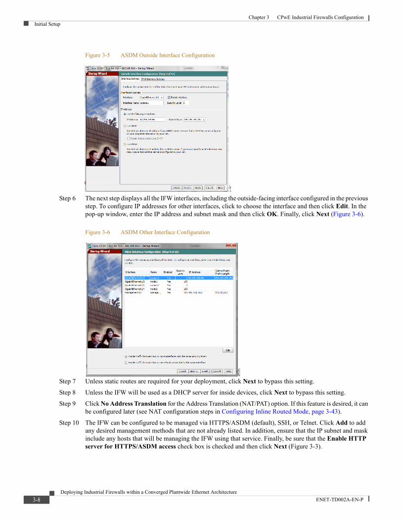
Chapter 3 CPwE Industrial Firewalls ConfigurationInitial Setup
Figure 3-5 ASDM Outside Interface Configuration
Step 6 The next step displays all the IFW interfaces, including the outside-facing interface configured in the previous step. To configure IP addresses for other interfaces, click to choose the interface and then click Edit. In the pop-up window, enter the IP address and subnet mask and then click OK. Finally, click Next (Figure 3-6).
Figure 3-6 ASDM Other Interface Configuration
Step 7 Unless static routes are required for your deployment, click Next to bypass this setting.
Step 8 Unless the IFW will be used as a DHCP server for inside devices, click Next to bypass this setting.
Step 9 Click No Address Translation for the Address Translation (NAT/PAT) option. If this feature is desired, it can be configured later (see NAT configuration steps in Configuring Inline Routed Mode, page 3-43).
Step 10 The IFW can be configured to be managed via HTTPS/ASDM (default), SSH, or Telnet. Click Add to add any desired management methods that are not already listed. In addition, ensure that the IP subnet and mask include any hosts that will be managing the IFW using that service. Finally, be sure that the Enable HTTP server for HTTPS/ASDM access check box is checked and then click Next (Figure 3-3).
3-8Deploying Industrial Firewalls within a Converged Plantwide Ethernet Architecture
ENET-TD002A-EN-P
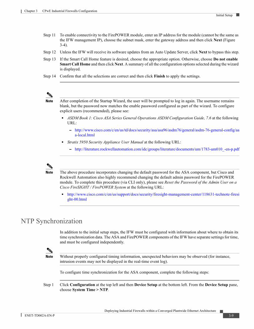
Chapter 3 CPwE Industrial Firewalls ConfigurationInitial Setup
Step 11 To enable connectivity to the FirePOWER module, enter an IP address for the module (cannot be the same as the IFW management IP), choose the subnet mask, enter the gateway address and then click Next (Figure 3-4).
Step 12 Unless the IFW will receive its software updates from an Auto Update Server, click Next to bypass this step.
Step 13 If the Smart Call Home feature is desired, choose the appropriate option. Otherwise, choose Do not enable Smart Call Home and then click Next. A summary of all the configuration options selected during the wizard is displayed.
Step 14 Confirm that all the selections are correct and then click Finish to apply the settings.
Note After completion of the Startup Wizard, the user will be prompted to log in again. The username remains blank, but the password now matches the enable password configured as part of the wizard. To configure explicit users (recommended), please see:
• ASDM Book 1: Cisco ASA Series General Operations ASDM Configuration Guide, 7.6 at the following URL:
– http://www.cisco.com/c/en/us/td/docs/security/asa/asa96/asdm76/general/asdm-76-general-config/aaa-local.html
• Stratix 5950 Security Appliance User Manual at the following URL:
– http://literature.rockwellautomation.com/idc/groups/literature/documents/um/1783-um010_-en-p.pdf
Note The above procedure incorporates changing the default password for the ASA component, but Cisco and Rockwell Automation also highly recommend changing the default admin password for the FirePOWER module. To complete this procedure (via CLI only), please see Reset the Password of the Admin User on a Cisco FireSIGHT / FirePOWER System at the following URL:
• http://www.cisco.com/c/en/us/support/docs/security/firesight-management-center/118631-technote-firesight-00.html
NTP Synchronization
In addition to the initial setup steps, the IFW must be configured with information about where to obtain its time synchronization data. The ASA and FirePOWER components of the IFW have separate settings for time, and must be configured independently.
Note Without properly configured timing information, unexpected behaviors may be observed (for instance, intrusion events may not be displayed in the real-time event log).
To configure time synchronization for the ASA component, complete the following steps:
Step 1 Click Configuration at the top left and then Device Setup at the bottom left. From the Device Setup pane, choose System Time > NTP.
3-9Deploying Industrial Firewalls within a Converged Plantwide Ethernet Architecture
ENET-TD002A-EN-P

Chapter 3 CPwE Industrial Firewalls ConfigurationInitial Setup
Step 2 Click Add to open the NTP server configuration window. For IP Address, enter the IP address of the NTP server, and check the Preferred check box to make this server the definitive time source. Choose from the Interface drop-down menu if NTP packets should be sent out of a particular interface. Finally, enter any NTP authentication information in the Authentication Key section of the window and then click OK (Figure 3-7).
Figure 3-7 ASDM ASA Add NTP Server Configuration Window
Step 3 Confirm the NTP server settings that are displayed in the table and then click Apply to make the changes take effect (Figure 3-8).
Figure 3-8 ASDM ASA NTP Server Configuration Table
Step 4 Once the synchronization is complete, in the Device Setup pane choose System Time > Clock and check the Time section to confirm that the ASA is receiving its time from the NTP server and that the current time is accurate (Figure 3-9).
3-10Deploying Industrial Firewalls within a Converged Plantwide Ethernet Architecture
ENET-TD002A-EN-P

Chapter 3 CPwE Industrial Firewalls ConfigurationInitial Setup
Figure 3-9 ASDM ASA Clock Settings Window
The equivalent CLI for this interface configuration is shown below:
ntp server 192.168.254.20 prefer
To configure time synchronization for the FirePOWER component, complete the following steps:
Step 1 Click Configuration at the top left and then ASA FirePOWER Configuration at the bottom left. From the ASA FirePOWER Configuration pane, choose Local > System Policy.
Step 2 For the policy labeled Initial System Policy, click the small pencil icon on the right side to edit the policy.
Step 3 On the left side of the edit window click the Time Synchronization option. Next to Set My Clock, check the Via NTP from radio button and enter the IP address of the NTP server (it should be the same as the one for the ASA component). Finally, click Save Policy and then click Exit (Figure 3-10).
Figure 3-10 ASDM FirePOWER Time Synchronization Settings
Step 4 Check the green check box to the right of the Initial System Policy to apply the changes. After the process has completed, a small window will appear at the top labeled Success (Figure 3-11).
3-11Deploying Industrial Firewalls within a Converged Plantwide Ethernet Architecture
ENET-TD002A-EN-P

Chapter 3 CPwE Industrial Firewalls ConfigurationInitial Setup
Figure 3-11 ASDM FirePOWER Initial System Policy Applied Changes
Step 5 To confirm time synchronization is working properly, in the ASA FirePOWER Configuration pane, choose Local > Configuration > Time. The NTP server should be listed here with a status of Being Used (Figure 3-12).
Figure 3-12 ASDM FirePOWER Time Settings Window
3-12Deploying Industrial Firewalls within a Converged Plantwide Ethernet Architecture
ENET-TD002A-EN-P

Chapter 3 CPwE Industrial Firewalls ConfigurationConfiguring Inline Transparent Mode
Configuring Inline Transparent ModeThis section describes how to customize the IFW configuration when being deployed in inline transparent mode.
Interface Configuration
Interface configuration on the IFW varies depending on where in the industrial network the device will be deployed, so this section is divided into subsections describing configuration for each deployment model. Figure 3-13 shows the Interfaces configuration view in ASDM after following the initial setup procedure. Each type of interface, including physical, virtual and management, can be configured here.
Figure 3-13 ASDM Interface Configuration View with Default Settings
Machine/Skid Protection (Single Access Link)
This section assumes that the IFW is being deployed in inline transparent mode on a single access link between an IACS device or machine/skid and the local IES, as detailed in Machine/Skid Protection, page 2-23.
For this model, no additional interface configuration is necessary because the GigabitEthernet 1/1 and 1/2 interfaces are already mapped to the same (default) bridge group. Once the Bridged Virtual Interface (BVI) and access rules have been properly configured, traffic will flow between these interfaces (see the BVI and Access Rule Configuration sections).
Note GigabitEthernet 1/1 (outside1) should be connected to the IES and GigabitEthernet 1/2 (inside1) should be connected to the IACS device or machine/skid for this deployment model. This setup is required for the hardware bypass feature to function correctly, and also conforms to typical outside and inside terminology usage.
The equivalent CLI for this interface configuration is shown below:
3-13Deploying Industrial Firewalls within a Converged Plantwide Ethernet Architecture
ENET-TD002A-EN-P

Chapter 3 CPwE Industrial Firewalls ConfigurationConfiguring Inline Transparent Mode
interface GigabitEthernet1/1 nameif outside1 bridge-group 1 security-level 0!interface GigabitEthernet1/2 nameif inside1 bridge-group 1 security-level 100!
If each side of the IFW will be connected to a switch (for instance, the IFW is placed inline between an IES and a switch connected to the machine/skid IACS devices, it is recommended to configure a custom Smartport on switch ports using these commands:
switchport mode accessswitchport access vlan $access_vlanservice-policy input CIP-PTP-Trafficpriority-queue outsrr-queue bandwidth share 1 19 40 40alarm profile ab-alarmload-interval 30no cdp enableno udld port aggressivemls qos trust dscp
Cell/Area Zone Protection (EtherChannel Trunk Link)
This section assumes that the IFW is being deployed in inline transparent mode on a redundant (EtherChannel) link between a Cell/Area Zone and the distribution switch for that Cell/Area, as detailed in Redundant Star Cell/Area Zone Protection, page 2-26. However, these configurations are always required when the IFW is placed inline with a trunk link.
For this model, the IFW does not support transporting traffic between interfaces with its VLAN tag intact, which is required on a trunk link that carries VLAN-tagged traffic. Therefore, the IFW must be configured to match separate VLANs on each interface and “translate" these VLANs by pairing the interfaces via a bridge group. This is accomplished by completing the following steps:
1. Subinterfaces are configured to match each VLAN arriving on the trunk link from the Cell/Area Zone switch.
2. Each VLAN is assigned an alternative VLAN to carry the traffic toward the distribution switch, and subinterfaces are then configured to match each of these alternative VLANs.
3. Each corresponding set of subinterfaces are mapped together into a bridge group to allow the traffic to flow between them (but not to other subinterfaces).
Figure 3-14 shows an example of how the IFW interfaces could be configured for this model with a single VLAN carried on the trunk link (note that multiple VLANs are also supported on the trunk link with similar configurations for each one).
3-14Deploying Industrial Firewalls within a Converged Plantwide Ethernet Architecture
ENET-TD002A-EN-P

Chapter 3 CPwE Industrial Firewalls ConfigurationConfiguring Inline Transparent Mode
Figure 3-14 Inline Transparent Interface Configuration Example for EtherChannel Trunk Link
To configure the IFW interfaces according to this example, complete the following steps:
Step 1 Click Configuration at the top left and then Device Setup at the bottom left. From the Device Setup pane, choose Interface Settings > Interfaces.
Step 2 On the right side, click Add and then choose EtherChannel Interface.
Step 3 Enter a port-channel ID value--typically a value that will match the one configured on the distribution switch (example: 2). Do not choose a bridge group, since the subinterfaces will be bridged together and not the main EtherChannel interface. Enter a name for the interface (example: outside) and a security level (example: 0, default for outside). Make sure that the Enable Interface check box is checked. From the Available Physical Interfaces box, choose each of the interfaces that should be included in the EtherChannel (example: Gi1/1 and Gi1/2). Finally, click OK to create the interface (Figure 3-15).
3-15Deploying Industrial Firewalls within a Converged Plantwide Ethernet Architecture
ENET-TD002A-EN-P

Chapter 3 CPwE Industrial Firewalls ConfigurationConfiguring Inline Transparent Mode
Figure 3-15 ASDM EtherChannel Interface Configuration
Step 4 On the right side, click Add and then click Interface.
Step 5 Choose the Hardware Port as the EtherChannel interface just created, then enter a VLAN ID and corresponding subinterface ID (example: 21). Choose a bridge group that the subinterface should be placed in (example: 1). Enter a name for the interface (example: vlan20_outside) and a security level (example: 0, to coincide with main interface). Make sure that the Enable Interface check box is checked. Finally, click OK to create the subinterface (Figure 3-16).
3-16Deploying Industrial Firewalls within a Converged Plantwide Ethernet Architecture
ENET-TD002A-EN-P

Chapter 3 CPwE Industrial Firewalls ConfigurationConfiguring Inline Transparent Mode
Figure 3-16 ASDM EtherChannel Subinterface Configuration
Step 6 Repeat Steps 1-4 to create the EtherChannel interface and associated subinterface for the link facing the IES. The Interfaces configuration view should now look similar to Figure 3-17.
Figure 3-17 ASDM Interface Configuration View with Configured EtherChannels and Subinterfaces
Step 7 Repeat Steps 3-4 to create subinterfaces on each EtherChannel interface for any other trunked VLANs that must be transported via the IFW.
Step 8 At the bottom of the window, click Apply to make the changes take effect. The equivalent CLI for this interface configuration is shown below:
interface GigabitEthernet1/1 channel-group 2 mode active no nameif no security-level!
3-17Deploying Industrial Firewalls within a Converged Plantwide Ethernet Architecture
ENET-TD002A-EN-P

Chapter 3 CPwE Industrial Firewalls ConfigurationConfiguring Inline Transparent Mode
interface GigabitEthernet1/2 channel-group 4 mode active no nameif no security-level!interface GigabitEthernet1/3 channel-group 2 mode active no nameif no security-level!interface GigabitEthernet1/4 channel-group 4 mode active no nameif no security-level!interface Port-channel2 lacp max-bundle 8 nameif outside security-level 0!interface Port-channel2.21 vlan 21 nameif vlan20_outside bridge-group 1 security-level 0!interface Port-channel4 lacp max-bundle 8 nameif inside security-level 100!interface Port-channel4.20 vlan 20 nameif vlan20_inside bridge-group 1 security-level 100!
Note When running the IFW in inline transparent mode, for any switch ports connected to the IFW, use the same Smartport settings as if the devices on each side of the IFW were directly connected.
Bridged Virtual Interface Configuration
During completion of the Startup Wizard as part of the IFW initial setup, the BVI created by default for bridge group 1 is assigned an IP address so that traffic can flow within that bridge group. Generally, this IP address must fall within the subnet connected to the IFW and used by that bridge group to function properly. To edit the existing BVI settings, complete the following steps:
Step 1 Click Configuration at the top left and then click Device Setup at the bottom left. From the Device Setup pane, choose Interface Settings > Interfaces.
Step 2 Choose the BVI in the list and on the right side, click Edit.
Step 3 Change the IP address and/or subnet mask as needed and then click OK (Figure 3-18).
3-18Deploying Industrial Firewalls within a Converged Plantwide Ethernet Architecture
ENET-TD002A-EN-P

Chapter 3 CPwE Industrial Firewalls ConfigurationConfiguring Inline Transparent Mode
Step 4 At the bottom of the window, click Apply to make the changes take effect.
Figure 3-18 ASDM Bridge Group Interface Configuration (Edit)
The equivalent CLI for this BVI configuration is shown below:
interface BVI1 ip address 10.17.20.155 255.255.255.0!
BVI Configuration for Trunked Connections
Multiple bridge groups are required any time multiple VLANs are used on a trunk link. Each VLAN on the trunk must have a BVI created, with the IP address of the BVI assigned within the IP address range of the VLAN. For example, if a trunk carries three VLANs as follows:
• VLAN 10: subnet 10.10.10.0/24,
• VLAN 20: subnet 10.10.20.0/24
• VLAN 30: subnet 10.10.30.0/24
then three individual BVIs must be created with IP addresses within their corresponding VLAN subnet. For example:
• BVI1 (For VLAN 10): assigned an IP Address within 10.10.10.1-10.10.10.254
• BVI2 (For VLAN 20): assigned an IP Address within 10.10.20.1-10.10.20.254
• BVI3 (For VLAN 30): assigned an IP Address within 10.10.30.1-10.10.30.254
After a BVI is created for each VLAN, a subinterface for each VLAN must be created on each physical interface so it can be assigned to each VLAN's BVI (as detailed in the previous section). For example, the following subinterfaces would be created for interface GigabitEthernet1/2:
• GigabitEthernet1/2.10 : subinterface assigned to bridge group 1 (BVI1) to support VLAN 10 traffic
• GigabitEthernet1/2.20 : subinterface assigned to bridge group 2 (BVI2) to support VLAN 20 traffic
• GigabitEthernet1/2.30 : subinterface assigned to bridge group 3 (BVI3) to support VLAN 30 traffic
When the IFW is used in inline transparent mode, only unique VLAN IDs can be assigned to each subinterface. For instance, if VLAN 10 is assigned to subinterface GigabitEthernet1/2.10, then it cannot be assigned to another subinterface. Due to this configuration rule enforcement, an additional VLAN ID must be chosen for each VLAN that will be trunked through the IFW. For instance, given the previous example,
3-19Deploying Industrial Firewalls within a Converged Plantwide Ethernet Architecture
ENET-TD002A-EN-P

Chapter 3 CPwE Industrial Firewalls ConfigurationConfiguring Inline Transparent Mode
three additional VLANs and subinterfaces would be created: GigabitEthernet1/1.110 with a VLAN ID of 110, GigabitEthernet1/1.120 with a VLAN ID of 120, and GigabitEthernet1/1.130 with a VLAN ID of 130 respectively to GigabitEthernet1/1. Each pair of subinterfaces, representing a trunked VLAN, is then assigned to the appropriate bridge group:
• GigabitEthernet1/1.110 : subinterface assigned to bridge group 1 (BVI1) to support VLAN 10 traffic
• GigabitEthernet1/1.120 : subinterface assigned to bridge group 2 (BVI2) to support VLAN 20 traffic
• GigabitEthernet1/1.130 : subinterface assigned to bridge group 3 (BVI3) to support VLAN 30 traffic
By associating the subinterface pairs to separate bridge groups, the IFW is effectively bridging VLAN 110 to VLAN 10, VLAN 120 to VLAN 20, and VLAN 130 to VLAN 30.
To create a new BVI when multiple bridge groups are required (multiple VLANs on a trunk link that must be separately bridged), complete the following steps:
Step 1 Click Configuration at the top left and then click Device Setup at the bottom left. From the Device Setup pane, choose Interface Settings > Interfaces.
Step 2 On the right side, click Add and then click Bridge Group Interface.
Step 3 Enter a unique ID for the bridge group, along with the IP address and subnet mask and then click OK to create the BVI (Figure 3-19).
Step 4 At the bottom of the window, click Apply to make the changes take effect.
Figure 3-19 ASDM Bridge Group Interface Configuration (New)
The equivalent CLI for this BVI configuration is shown below:
interface BVI2 ip address 10.17.21.155 255.255.255.0!
Access Rule Configuration
The IFW is configured just like a traditional Cisco Adaptive Security Appliance firewall, with rules that permit or deny (drop) particular traffic types arriving at an interface. This section describes how to configure a typical set of access rules for an industrial environment for each inline deployment model described in CPwE Industrial Firewalls Design Considerations
3-20Deploying Industrial Firewalls within a Converged Plantwide Ethernet Architecture
ENET-TD002A-EN-P

Chapter 3 CPwE Industrial Firewalls ConfigurationConfiguring Inline Transparent Mode
Note The access rules configured on an IFW may vary across deployments due to the wide variety of applications in use across industrial networks. The configurations shown in this section are only intended to be examples.
Machine/Skid Protection
The access rule configuration for this use case assumes that the following are the only valid types of traffic that should be allowed to traverse the IFW:
• CIP implicit (Class 1) - UDP port 2222
• CIP explicit (Class 3) - TCP (or UDP) port 44818
• HTTP for management interface access for IACS devices (only from Remote Access Server - see Figure 1-2 on page 1-3 - in this example)
All other traffic in all directions is assumed to be invalid and therefore should be dropped.
To configure the access rules for this use case, complete the following steps:
Step 1 Click Configuration at the top left and then Firewall at the bottom left. From the Firewall pane, choose Access Rules.
Note Since an ACL called “allowAll” is applied to all interfaces on the IFW by default (to confirm that traffic flows through the device out of the box), making a change to the access rules of a single interface using ASDM actually changes the allowAll ACL in the background, resulting in the same change being applied to all interfaces. Therefore, Cisco and Rockwell Automation recommend deleting the existing access rule (before deployment or during a maintenance window), then recreating individual access rules for each interface as needed. To delete the existing rule, choose it under any interface and then click Delete at the top. Then, continue with the procedure as given below.
Step 2 Choose the interface in the list that requires an access rule for incoming traffic and then click Add at the top.
Step 3 Choose the Permit action and then click the button to the right of the Service field.
Step 4 Scan through the list to choose the desired service. If this service object is not yet defined, click Add at the top and then choose Service Object. Enter a name for the object, choose a service type (TCP or UDP) and then enter the destination port number and a description of the defined service. Finally, click OK (Figure 3-20).
3-21Deploying Industrial Firewalls within a Converged Plantwide Ethernet Architecture
ENET-TD002A-EN-P

Chapter 3 CPwE Industrial Firewalls ConfigurationConfiguring Inline Transparent Mode
Figure 3-20 ASDM Service Object Configuration
Step 5 Once the service object has been created, choose it from the list and double-click to add it to the Selected Service list at the bottom of the window. Then click OK (Figure 3-21).
Note More than one service can be included in an access rule if desired. Each service that is double-clicked is added to the list.
Figure 3-21 ASDM Access Rule Service Selection
Step 6 The service list should now appear in the Service box. Enter a description for the purpose of the access rule and make sure that the Enable Logging check box is checked. Finally, click OK to create the rule (Figure 3-22).
3-22Deploying Industrial Firewalls within a Converged Plantwide Ethernet Architecture
ENET-TD002A-EN-P

Chapter 3 CPwE Industrial Firewalls ConfigurationConfiguring Inline Transparent Mode
Figure 3-22 ASDM New Access Rule Configuration
Step 7 Using the procedure from Steps 1-5, create the following Permit rules on the inside1 interface to allow CIP communication from behind the IFW:
Source = any, Destination = any, Service = CIP implicit (UDP port 2222), CIP explicit (TCP port 44818), CIP explicit (UDP port 44818)
Step 8 Create a Deny All rule using the procedure from Steps 1-5, but choose Deny as the action and leave the service to the default setting of IP. Make sure that this rule is the last rule listed under the interface. If not, click the rule and then click the down arrow until the rule is listed last.
Note Access rules for each interface are evaluated in order, so if the Deny All rule is configured earlier in the list than a Permit rule, traffic matching the Permit rule will always be dropped.
Step 9 Again, using the procedure from Steps 1-5, create the following Permit rules on the outside1 interface to allow CIP and HTTP communication from the industrial network:
Source = any, Destination = any, Service = CIP implicit (UDP port 2222), CIP explicit (TCP port 44818), CIP explicit (UDP port 44818)Source = <RAS IP address>, Destination = any, Service = http (TCP port 80)
Step 10 Again, create a Deny All rule using the procedure from Steps 1-5, but choose Deny as the action and leave the service to the default setting of IP. Make sure that this rule is the last rule listed under the interface. If not, click the rule and then click the down arrow until the rule is listed last.
Step 11 Click Apply at the bottom of the window to make the changes take effect. The access rule configuration view should now appear similar to Figure 3-23.
3-23Deploying Industrial Firewalls within a Converged Plantwide Ethernet Architecture
ENET-TD002A-EN-P

Chapter 3 CPwE Industrial Firewalls ConfigurationConfiguring Inline Transparent Mode
Figure 3-23 ASDM Access Rule Configuration View with Completed Rules - Machine/Skid Protection
Note When RSLinx is used to dynamically discover IACS devices behind the IFW, it may be necessary to add two separate access rules for CIP explicit UDP traffic, as shown in Figure 3-23 (and in the CLI below). The outside1 interface should have a rule permitting UDP traffic with a destination port of 44818 (cip-explicit-udp), while the inside1 interface should permit the same traffic but sourced from port 44818 instead (cip-explicit-udp-reply). This is due to the discovery message being destined for the broadcast address of the local subnet, while the response is sent directly from the end device, so the IFW cannot associate the messages as being part of the same connection.
The equivalent CLI for this access rule configuration is shown below:
object service cip-implicit service udp source eq 2222 destination eq 2222object service cip-explicit-tcp service tcp destination eq 44818object service cip-explicit-udp service udp destination eq 44818object service cip-explicit-udp-reply service udp source eq 44818object network RAS host 10.13.48.28object-group service DM_INLINE_SERVICE_2 service-object object cip-explicit-tcp service-object object cip-explicit-udp-reply service-object object cip-implicitobject-group service DM_INLINE_SERVICE_3 service-object object cip-explicit-tcp service-object object cip-explicit-udp service-object object cip-implicit!access-list inside1_access_in remark Allow CIP discovery and communicationaccess-list inside1_access_in extended permit object-group DM_INLINE_SERVICE_2 any anyaccess-list outside1_access_in remark Allow access from RAS to web management interface of PACaccess-list outside1_access_in extended permit tcp object RAS any eq wwwaccess-list outside1_access_in extended deny ip any any!
3-24Deploying Industrial Firewalls within a Converged Plantwide Ethernet Architecture
ENET-TD002A-EN-P

Chapter 3 CPwE Industrial Firewalls ConfigurationConfiguring Inline Transparent Mode
access-group outside1_access_in in interface outside1access-group inside1_access_in in interface inside1
Cell/Area Zone Protection
The access rule configuration for this use case assumes that the following are the only valid types of traffic that should be allowed to traverse the IFW:
• CIP implicit (Class 1), if needed for communication between Cell/Area Zones - UDP port 2222
• CIP explicit (Class 3) - TCP (or UDP) port 44818
• HTTP for management interface access for IACS devices (from Remote Access Server - see Figure 1-2 on page 1-3 - only)
All other traffic in all directions is assumed to be invalid and therefore dropped.
To configure the access rules for this use case, complete the following steps (refer to the figures from the previous section):
Step 1 Click Configuration at the top left and then Firewall at the bottom left. From the Firewall pane, choose Access Rules.
Note Since an ACL called allowAll is applied to all interfaces on the IFW by default (to confirm that traffic flows through the device out of the box), making a change to the access rules of a single interface using ASDM actually changes the allowAll ACL in the background, resulting in the same change being applied to all interfaces. Therefore, Cisco and Rockwell Automation recommend deleting the existing access rule (before deployment or during a maintenance window) and then recreating individual access rules for each interface as needed. To delete the existing rule, choose it under any interface and then click Delete at the top. Then, continue with the procedure as given below.
Step 2 Choose the interface in the list that requires an access rule for incoming traffic and then click Add at the top.
Step 3 Choose the Permit action and then click the button to the right of the Service field.
Step 4 Scroll through the list to choose the desired service. If this service object is not yet defined, click Add at the top and then choose Service Object. Enter a name for the object, choose a service type (TCP or UDP) and then enter the destination port number and a description of the defined service. Finally, click OK.
Step 5 Since the service object has been created, choose it from the list and double-click to add it to the Selected Service list at the bottom of the window and then click OK.
Note More than one service can be included in an access rule if desired. Each service that is double-clicked is added to the list.
Step 6 The service list should now appear in the Service box. Enter a description for the purpose of the access rule and make sure that the Enable Logging check box is checked. Finally, click OK to create the rule.
Step 7 Using the procedure from Steps 1-5, create the following Permit rule on the inside interface to allow CIP communication from behind the IFW:
Source = any, Destination = any, Service = CIP implicit (UDP port 2222), CIP explicit (TCP port 44818), CIP explicit (UDP port 44818)
3-25Deploying Industrial Firewalls within a Converged Plantwide Ethernet Architecture
ENET-TD002A-EN-P

Chapter 3 CPwE Industrial Firewalls ConfigurationConfiguring Inline Transparent Mode
Step 8 Create a Deny All rule using the procedure from Steps 1-5, but selecting Deny as the action and leaving the service to the default setting of IP. Make sure that this rule is the last rule listed under the interface. If not, click the rule and then click the down arrow at the top until the rule is listed last.
Note Access rules for each interface are evaluated in order, so if the Deny All rule is configured earlier in the list than a Permit rule, traffic matching the Permit rule will always be dropped.
Step 9 Again, using the procedure from Steps 1-5, create the following Permit rules on the outside interface to allow CIP and HTTP communication from the industrial network:
Source = any, Destination = any, Service = CIP implicit (UDP port 2222), CIP explicit (TCP port 44818), CIP explicit (UDP port 44818)Source = <RAS IP address>, Destination = any, Service = http (TCP port 80)
Step 10 Again, create a Deny All rule using the procedure from Steps 1-5, but selecting Deny as the action and leaving the service to the default setting of IP. Make sure that this rule is the last rule listed under the interface. If not, click the rule and then click the down arrow at the top until the rule is listed last.
Step 11 Click Apply at the bottom of the window to make the changes take effect. The Access Rules configuration view should now appear similar to Figure 3-24.
Figure 3-24 ASDM Access Rule Configuration View with Completed Rules - Cell/Area Zone Protection
The equivalent CLI for this access rule configuration is shown below:
object service cip-explicit-tcp service tcp destination eq 44818object service cip-implicit service udp source eq 2222 destination eq 2222object service cip-explicit-udp service udp destination eq 44818object service cip-explicit-udp-reply service udp source eq 44818object network RAS host 10.13.48.28object-group service DM_INLINE_SERVICE_1 service-object object cip-explicit-tcp
3-26Deploying Industrial Firewalls within a Converged Plantwide Ethernet Architecture
ENET-TD002A-EN-P

Chapter 3 CPwE Industrial Firewalls ConfigurationConfiguring Inline Transparent Mode
service-object object cip-explicit-udp-reply service-object object cip-implicitobject-group service DM_INLINE_SERVICE_3 service-object object cip-explicit-tcp service-object object cip-explicit-udp service-object object cip-implicit!access-list vlan20_inside_access_in remark Allow CIP discovery and communicationaccess-list vlan20_inside_access_in extended permit object-group DM_INLINE_SERVICE_1 any anyaccess-list vlan20_inside_access_in extended deny ip any anyaccess-list vlan20_outside_access_in remark Allow CIP discovery and communicationaccess-list vlan20_outside_access_in extended permit object-group DM_INLINE_SERVICE_3 any anyaccess-list vlan20_outside_access_in remark Allow access from RAS to web management interface of PACaccess-list vlan20_outside_access_in extended permit tcp object RAS any eq wwwaccess-list vlan20_outside_access_in extended deny ip any any!access-group vlan20_outside_access_in in interface vlan20_outsideaccess-group vlan20_inside_access_in in interface vlan20_inside
Hardware Bypass Configuration
Hardware bypass configuration on the IFW varies depending on where in the industrial network the device will be deployed, so this section is divided into subsections describing configuration for each deployment model.
Note Hardware bypass is only supported when the IFW is running in transparent mode.
For reference, Figure 3-25 shows the hardware bypass configuration view in ASDM with default settings (choose Configuration at the top left, choose Device Management at the bottom left and then in the Device Management pane, choose Hardware Bypass).
3-27Deploying Industrial Firewalls within a Converged Plantwide Ethernet Architecture
ENET-TD002A-EN-P

Chapter 3 CPwE Industrial Firewalls ConfigurationConfiguring Inline Transparent Mode
Figure 3-25 ASDM Hardware Bypass Configuration View with Default Settings
Machine/Skid Protection (Single Access Link)
The use of the hardware bypass feature is supported for this use case. By default, hardware bypass is enabled on each set of copper interfaces (GigabitEthernet 1/1 and 1/2, as well as GigabitEthernet 1/3 and 1/4 for the IFW model with four RJ45 ports). If the feature is not desired, it can be disabled by unchecking the Enable Bypass during Power Down check box for each set of interface and then clicking Apply at the bottom of the screen. The equivalent CLI for this configuration is shown below:
[no] hardware-bypass GigabitEthernet 1/1-1/2[no] hardware-bypass GigabitEthernet 1/3-1/4! If applicable
Other configurable hardware bypass settings include the following:
• The default behavior of the IFW is to disable hardware bypass once it has come back online from a power disruption or reload event. This is the recommended setting. If the preferred behavior is for the IFW to remain in hardware bypass mode after coming back online, it can be configured by checking the Stay in Bypass after Power Up check box for each set of interfaces and then clicking Apply at the bottom of the screen. The equivalent CLI for this configuration is shown below:
hardware-bypass gigabitEthernet 1/1-1/2 [sticky]hardware-bypass gigabitEthernet 1/3-1/4 [sticky]! If applicable
• The default behavior of the Industrial Security Appliance 3000 is to disable hardware bypass as soon as the device is back online. Even if the FirePOWER module is configured for traffic inspection, traffic will not be inspected until the module is up and running. Therefore, a short period may occur where traffic is processed by the IFW but not inspected. The recommended setting is to change this behavior so that hardware bypass is not disabled until both the IFW device and FirePOWER module are ready. To configure this setting, check the Stay in Bypass until after the ASA Firepower Module Boots Up check box and then click Apply at the bottom of the screen. The equivalent CLI for this configuration is shown below:
[no] hardware-bypass boot-delay module-up sfr
3-28Deploying Industrial Firewalls within a Converged Plantwide Ethernet Architecture
ENET-TD002A-EN-P
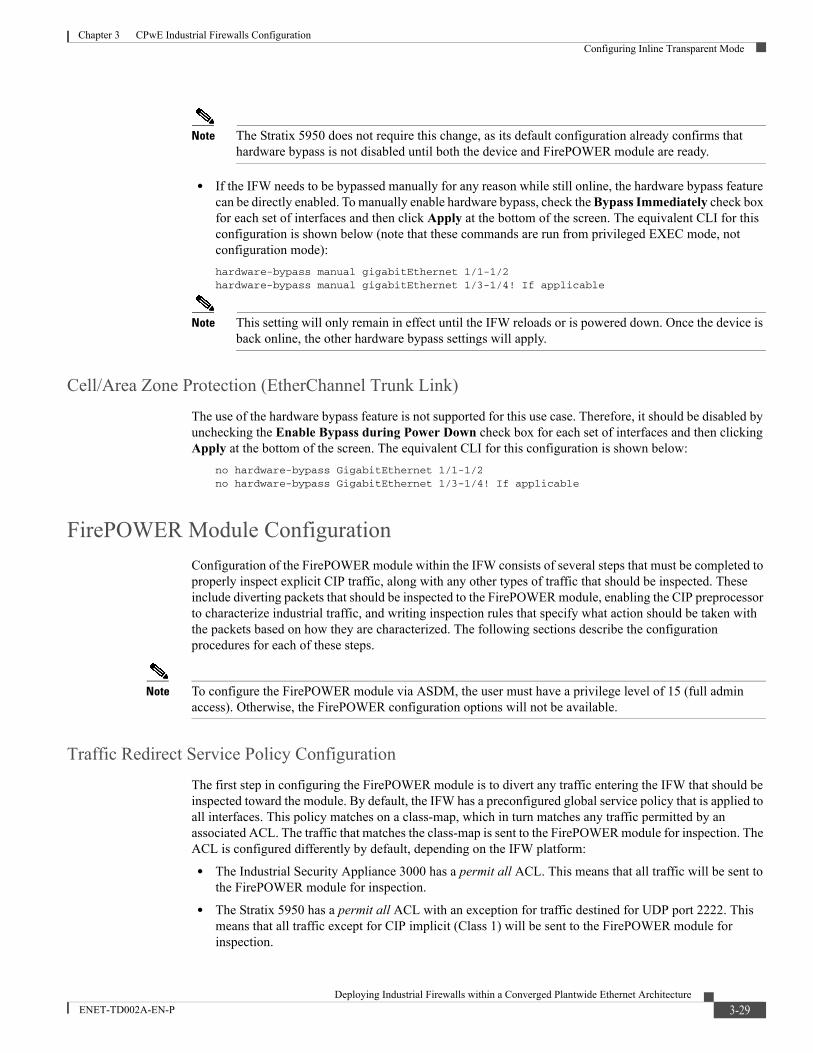
Chapter 3 CPwE Industrial Firewalls ConfigurationConfiguring Inline Transparent Mode
Note The Stratix 5950 does not require this change, as its default configuration already confirms that hardware bypass is not disabled until both the device and FirePOWER module are ready.
• If the IFW needs to be bypassed manually for any reason while still online, the hardware bypass feature can be directly enabled. To manually enable hardware bypass, check the Bypass Immediately check box for each set of interfaces and then click Apply at the bottom of the screen. The equivalent CLI for this configuration is shown below (note that these commands are run from privileged EXEC mode, not configuration mode):
hardware-bypass manual gigabitEthernet 1/1-1/2hardware-bypass manual gigabitEthernet 1/3-1/4! If applicable
Note This setting will only remain in effect until the IFW reloads or is powered down. Once the device is back online, the other hardware bypass settings will apply.
Cell/Area Zone Protection (EtherChannel Trunk Link)
The use of the hardware bypass feature is not supported for this use case. Therefore, it should be disabled by unchecking the Enable Bypass during Power Down check box for each set of interfaces and then clicking Apply at the bottom of the screen. The equivalent CLI for this configuration is shown below:
no hardware-bypass GigabitEthernet 1/1-1/2no hardware-bypass GigabitEthernet 1/3-1/4! If applicable
FirePOWER Module Configuration
Configuration of the FirePOWER module within the IFW consists of several steps that must be completed to properly inspect explicit CIP traffic, along with any other types of traffic that should be inspected. These include diverting packets that should be inspected to the FirePOWER module, enabling the CIP preprocessor to characterize industrial traffic, and writing inspection rules that specify what action should be taken with the packets based on how they are characterized. The following sections describe the configuration procedures for each of these steps.
Note To configure the FirePOWER module via ASDM, the user must have a privilege level of 15 (full admin access). Otherwise, the FirePOWER configuration options will not be available.
Traffic Redirect Service Policy Configuration
The first step in configuring the FirePOWER module is to divert any traffic entering the IFW that should be inspected toward the module. By default, the IFW has a preconfigured global service policy that is applied to all interfaces. This policy matches on a class-map, which in turn matches any traffic permitted by an associated ACL. The traffic that matches the class-map is sent to the FirePOWER module for inspection. The ACL is configured differently by default, depending on the IFW platform:
• The Industrial Security Appliance 3000 has a permit all ACL. This means that all traffic will be sent to the FirePOWER module for inspection.
• The Stratix 5950 has a permit all ACL with an exception for traffic destined for UDP port 2222. This means that all traffic except for CIP implicit (Class 1) will be sent to the FirePOWER module for inspection.
3-29Deploying Industrial Firewalls within a Converged Plantwide Ethernet Architecture
ENET-TD002A-EN-P

Chapter 3 CPwE Industrial Firewalls ConfigurationConfiguring Inline Transparent Mode
To configure the settings for this policy, complete the following steps:
Step 1 Click Configuration at the top left and then Firewall at the bottom left. From the Firewall pane, choose Service Policy Rules.
Step 2 Choose the sfrclass match statement and then click Edit at the top.
Step 3 On the Traffic Classification tab, make sure that the Source and Destination IP Address (uses ACL) check box is checked.
Step 4 On the ACL tab, choose the Match action and then click the button to the right of the Service field.
Step 5 Scroll through the list to choose the desired service or manually type the transport method (tcp or udp) followed by a slash (/) and then the port number of the service (example: tcp/44818 for CIP explicit messaging). Finally, click OK to return to the ACL tab (Figure 3-26).
Figure 3-26 ASDM Global Service Policy SFR Rule Configuration
Step 6 On the Rule Actions tab, choose the ASA FirePOWER Inspection tab. Make sure that the Enable ASA FirePOWER for this traffic flow check box is checked. To place the module in a fail-open state so that traffic will continue to pass through the IFW even if the module is down (recommended), choose the Permit traffic option under If ASA FirePOWER Card Fails. Finally, check the Enable Monitor Only check box if the IFW should send a copy of matching traffic to the FirePOWER module but forward the traffic anyway. This option is selected by default and is recommended during initial deployment stages to make sure that the traffic is not affected while inspection rules are being authored and tested. Figure 3-27 shows the recommended settings for the initial deployment stage.
Note Once the inspection rules have been finalized, the Enable Monitor Only option may be unselected to start sending all matching traffic via the FirePOWER module only.
3-30Deploying Industrial Firewalls within a Converged Plantwide Ethernet Architecture
ENET-TD002A-EN-P

Chapter 3 CPwE Industrial Firewalls ConfigurationConfiguring Inline Transparent Mode
Figure 3-27 ASDM FirePOWER Inspection Rule Actions Configuration
Step 7 From the Connection Settings tab, uncheck the Randomize Sequence Number check box.
Note This is the recommended setting to avoid unnecessary TCP connection drops when the hardware bypass feature takes effect. If hardware bypass is not being used, this step is not necessary.
Step 8 Click OK and then click Apply at the bottom of the window to make the changes take effect. The Service Policy Rules configuration view should now appear similar to Figure 3-28.
Figure 3-28 ASDM Service Policy Rules Configuration View with Customized Inspection Rule
The equivalent CLI for this access rule configuration is shown below:
access-list sfrAccessList extended permit tcp any any eq 44818
3-31Deploying Industrial Firewalls within a Converged Plantwide Ethernet Architecture
ENET-TD002A-EN-P

Chapter 3 CPwE Industrial Firewalls ConfigurationConfiguring Inline Transparent Mode
policy-map global_policy class sfrclass sfr fail-open monitor-only set connection random-sequence-number disable!service-policy global_policy global
CIP Preprocessor Configuration
By default, the CIP preprocessor of the FirePOWER module is disabled. To allow CIP traffic to be inspected by the module, the CIP preprocessor must be enabled and configured appropriately. To set up the module for CIP inspection, complete the following steps:
Step 1 Click Configuration at the top left and then ASA FirePOWER Configuration at the bottom left. From the ASA FirePOWER Configuration pane, choose Policies > Access Control Policy.
Step 2 Click the pencil icon to the right of the default policy to edit it.
Step 3 Click the Advanced tab and then click the pencil icon next to Network Analysis and Intrusion Policies to bring up the settings window.
Step 4 Click the Network Analysis Policy List link. In the resulting window, click Create Policy at the top right.
Step 5 Enter a name for the network analysis policy and a description, if desired. Make sure that the Inline Mode check box is checked so that the CIP preprocessor has the ability to block traffic when the IFW is deployed inline. Choose the desired base policy from the Base Policy drop-down menu. Finally, click Create and Edit Policy (Figure 3-29).
Figure 3-29 ASDM Network Analysis Policy Creation
3-32Deploying Industrial Firewalls within a Converged Plantwide Ethernet Architecture
ENET-TD002A-EN-P

Chapter 3 CPwE Industrial Firewalls ConfigurationConfiguring Inline Transparent Mode
Step 6 In the policy edit window, click Settings in the left panel. All available preprocessors will be displayed, along with whether they are enabled or disabled. Scroll down to the SCADA Preprocessors section and click the Enabled option next to CIP Configuration. Next, scroll down to the Transport/Network Layer Preprocessors and click Enabled next to Inline Normalization. Finally, click Edit to the right of TCP Stream Configuration, which should already be enabled (Figure 3-30).
Figure 3-30 ASDM CIP Preprocessor Enable Settings
Step 7 Scroll down under the Configuration header and locate the Perform Stream Reassembly on Both Ports setting. In the box to the right, enter 44818 at the end of the list (Figure 3-31).
3-33Deploying Industrial Firewalls within a Converged Plantwide Ethernet Architecture
ENET-TD002A-EN-P

Chapter 3 CPwE Industrial Firewalls ConfigurationConfiguring Inline Transparent Mode
Figure 3-31 ASDM TCP Stream Configuration Window
Step 8 Click Policy Information in the left panel (the yellow triangle indicates that the policy has been changed, but not committed). Click Commit Changes to apply all settings, and enter a description in the following window if wanted before clicking OK.
Step 9 The new network analysis policy should now be displayed in the list of policies (Figure 3-32). Close the window to return to ASDM.
Figure 3-32 ASDM Network Analysis Policy List with Configured Policy
Step 10 From the Default Network Analysis Policy drop-down menu, choose the policy that was just created and then click OK.
3-34Deploying Industrial Firewalls within a Converged Plantwide Ethernet Architecture
ENET-TD002A-EN-P

Chapter 3 CPwE Industrial Firewalls ConfigurationConfiguring Inline Transparent Mode
Step 11 The access control policy configuration will now reflect the new default network analysis policy (Figure 3-33). Click Apply ASA FirePOWER Changes to commit the changes and then click Apply All in the pop-up window. The apply task will start in the background (click the Task Status link in the final pop-up window to see the task progress).
Figure 3-33 ASDM Advanced Access Control Policy Settings with New Default Network Analysis Policy
Note More information on configuring the CIP preprocessor can be found at the following URLs:
• Stratix 5950 Security Appliance User Manual at the following URL:
– http://literature.rockwellautomation.com/idc/groups/literature/documents/um/1783-um010_-en-p.pdf
• FireSIGHT System User Guide Version 5.4.1- Configuring the CIP Preprocessor at the following URL:
– http://www.cisco.com/c/en/us/td/docs/security/firesight/541/user-guide/FireSIGHT-System-UserGuide-v5401/NAP-SCADA.html#pgfId-1552845
Inspection Rule Configuration (OpenAppID)
Inspection rules must be configured to specify what types of traffic will be flagged by the FirePOWER module and whether that flagged traffic will be allowed or blocked (for inline deployments). The most common approach is to configure inspection rules based on the applications identified by the module preprocessors (example: CIP Read or Write), which is known as OpenAppID. Although the ability to identify specific packet patterns is lost, this approach is more intuitive to configure. To define rules using the OpenAppID approach, which is implemented at the access control policy level, complete the following steps:
Step 1 Click Configuration at the top left and then ASA FirePOWER Configuration at the bottom left. From the ASA FirePOWER Configuration pane, choose Policies > Access Control Policy.
Step 2 Click New Policy at the top right. Enter a name for the policy, a description if desired and then choose the Intrusion Prevention option for Default Action. Finally, click Store ASA FirePOWER Changes to create the policy (Figure 3-34).
3-35Deploying Industrial Firewalls within a Converged Plantwide Ethernet Architecture
ENET-TD002A-EN-P
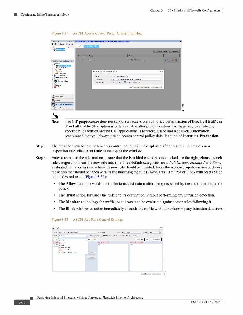
Chapter 3 CPwE Industrial Firewalls ConfigurationConfiguring Inline Transparent Mode
Figure 3-34 ASDM Access Control Policy Creation Window
Note The CIP preprocessor does not support an access control policy default action of Block all traffic or Trust all traffic (this option is only available after policy creation), as these may override any specific rules written around CIP applications. Therefore, Cisco and Rockwell Automation recommend that you always use an access control policy default action of Intrusion Prevention.
Step 3 The detailed view for the new access control policy will be displayed after creation. To create a new inspection rule, click Add Rule at the top of the window.
Step 4 Enter a name for the rule and make sure that the Enabled check box is checked. To the right, choose which rule category to insert the new rule into (the three default categories are Administrator, Standard and Root, evaluated in that order) and where the new rule should be inserted. From the Action drop-down menu, choose the action that should be taken with traffic matching the rule (Allow, Trust, Monitor or Block with reset) based on the desired result (Figure 3-35):
• The Allow action forwards the traffic to its destination after being inspected by the associated intrusion policy.
• The Trust action forwards the traffic to its destination without performing any intrusion detection.
• The Monitor action logs the traffic, but allows it to be evaluated against other rules following it.
• The Block with reset action immediately discards the traffic without performing any intrusion detection.
Figure 3-35 ASDM Add Rule General Settings
3-36Deploying Industrial Firewalls within a Converged Plantwide Ethernet Architecture
ENET-TD002A-EN-P

Chapter 3 CPwE Industrial Firewalls ConfigurationConfiguring Inline Transparent Mode
Note Although a Block option is also available, the Block with reset option is recommended when configuring rules for CIP communication. When the packet is blocked, the Block with reset option also cleanly resets the connection. If a CIP connection is blocked without a reset, unexpected behavior may occur, including IACS devices becoming unresponsive.
Step 5 Click the Networks tab to filter the rule to apply to specific networks or IP addresses. Networks can be entered manually by typing the values below the Source or Destination Networks lists and then clicking Add. Otherwise, a network object can be added by clicking the small plus sign next to Available Networks, and once added, the object can be selected and added as a source or destination (Figure 3-36).
Figure 3-36 ASDM Add Rule Network Settings
Step 6 Click the Applications tab to filter the rule to apply to specific application categories as identified by the FirePOWER module. Enter an application name (for example, CIP) under Application Filters to show matching categories for that application. Check the check box next to the categories that should be matched by the rule. Make sure that All apps matching the filter is selected in the Available Applications column and then click Add to Rule to list the selected categories in the Selected Applications and Filters column (Figure 3-37).
Figure 3-37 ASDM Add Rule Application Settings
Note While CIP applications may be selected individually for inclusion in an inspection rule, Cisco and Rockwell Automation recommend using categories to identify the application(s) being matched. CIP operations such as Read and Write can involve multiple types of communication, so identifying a single application for matching may cause other applications for that operation to go unmatched.
3-37Deploying Industrial Firewalls within a Converged Plantwide Ethernet Architecture
ENET-TD002A-EN-P

Chapter 3 CPwE Industrial Firewalls ConfigurationConfiguring Inline Transparent Mode
Step 7 If the rule action will result in intrusion detection being performed on the matched traffic (such as Allow), click the Inspection tab and choose an Intrusion Policy from the drop-down menu (Figure 3-38). The default selections define how strict of a rule set is applied to the traffic and range from Connectivity over Security (fewest rules) to Maximum Detection (most rules).
Figure 3-38 ASDM Add Rule Inspection Settings
Note The selected intrusion policy will depend on your company's security policies, although Connectivity over Security will most likely suffice for most deployments since availability is generally the highest priority in an industrial environment.
Step 8 Click the Logging tab and choose an option to define when logging will occur for a connection that matches the rule. After choosing this option, choose where connection events will be sent by checking the check box next to each desired option (Event Viewer by default, syslog server, or SNMP server) and adding a configuration if needed. Finally, click Add to complete the rule configuration (Figure 3-39).
Figure 3-39 ASDM Add Rule Logging Settings
Note Based upon the rule action, only valid logging options for that action will be made available for selection.
Note When configuring a rule with the Allow action for CIP communication, only the first and/or last packet sent within a TCP session will be logged as a rule-matching event. Other packets sent within that same TCP session will not be logged.
Step 9 Repeat Steps 3-8 for each additional rule that should be defined for the access control policy.
3-38Deploying Industrial Firewalls within a Converged Plantwide Ethernet Architecture
ENET-TD002A-EN-P

Chapter 3 CPwE Industrial Firewalls ConfigurationConfiguring Inline Transparent Mode
Step 10 Next to Default Action at the bottom of the rule list, choose the intrusion policy that should be applied in case any traffic does not match any of the configured rules (as stated earlier, only choose one of the Intrusion Prevention options, not Access Control).
Step 11 Click the Advanced tab and then click the pencil icon next to Network Analysis and Intrusion Policies. From the Default Network Analysis Policy drop-down menu, choose the policy that was created when configuring the CIP preprocessor. Finally, click OK (Figure 3-40).
Figure 3-40 ASDM Network Analysis and Intrusion Policy Selection
Step 12 With all rules and settings configured, click Store ASA FirePOWER Changes to save the policy configuration or click Apply ASA FirePOWER Changes to save and apply this policy to the FirePOWER module.
Note The FirePOWER module can only have one access control policy applied at a time. Applying a new policy will deactivate the existing policy.
Note More information on configuring access control policies can be found at the following URLs:
• Stratix 5950 Security Appliance User Manual at the following URL:
– http://literature.rockwellautomation.com/idc/groups/literature/documents/um/1783-um010_-en-p.pdf
• ASA FirePOWER Module User Guide for the ASA5506-X, ASA5506H-X, ASA5506W-X, ASA5508-X, and ASA5516-X, Version 5.4.1 - Getting Started with Access Control Policies at the following URL:
– http://www.cisco.com/c/en/us/td/docs/security/firesight/541/firepower-module-user-guide/asa-firepower-module-user-guide-v541/AC-Getting-Started.html
Inspection Rule Configuration (IPS)
More detailed inspection rules, which can match on individual fields within a packet (for example, CIP class and service fields), can be configured to flag certain values associated with a known vulnerability or other undesired traffic. Although more granular, these rules are also less intuitive to configure. To define inspection rules using the IPS (packet-based) approach, which is implemented at the intrusion policy level, complete the following steps:
3-39Deploying Industrial Firewalls within a Converged Plantwide Ethernet Architecture
ENET-TD002A-EN-P

Chapter 3 CPwE Industrial Firewalls ConfigurationConfiguring Inline Transparent Mode
Step 1 Click Configuration at the top left and then click ASA FirePOWER Configuration at the bottom left. From the ASA FirePOWER Configuration pane, choose Policies > Intrusion Policy > Rule Editor.
Step 2 Click Create Rule at the top right.
Step 3 In the Message field, enter a descriptive name for the rule. From the Classification drop-down menu, choose the most appropriate description of the type of violation being described by the rule. From the Action drop-down menu, choose whether a rule match should trigger an alert or simply pass the packet. From the Protocol and Direction drop-down menus, choose the appropriate protocol type and whether the rule will apply in one or both directions of traffic flow. If the rule should only match packets with certain source and destination IP addresses or ports, enter that information as well in the corresponding fields.
Step 4 Under Detection Options, choose a particular packet field to match on, click Add Option, and then enter the value to match for that field in the text box. Repeat this step for all packet fields that should be matched as part of the rule. Finally, click Save as New to create the rule (Figure 3-41).
Figure 3-41 ASDM Intrusion Rule Creation Window
Step 5 A success message will be displayed once the rule has been created. Click the Rule Editor link at the top of the window to return to the rule list. For any additional rules that should be configured, repeat Steps 2-3.
Step 6 Next, click Intrusion Policy above Rule Editor in the ASA FirePOWER Configuration pane. To create a new intrusion policy, click Create Policy at the top right.
Step 7 Enter a name in the Name field and a description, if desired. If the policy should have the ability to drop traffic, check the Drop when Inline check box. Choose a policy from the Base Policy drop-down menu to define how strict of a baseline rule set is applied to the traffic - these range from Connectivity over Security (fewest rules) to Maximum Detection (most rules). Finally, click Create and Edit Policy (Figure 3-42).
Figure 3-42 ASDM Intrusion Policy Creation Window
3-40Deploying Industrial Firewalls within a Converged Plantwide Ethernet Architecture
ENET-TD002A-EN-P

Chapter 3 CPwE Industrial Firewalls ConfigurationConfiguring Inline Transparent Mode
Note The selected base policy will depend on your company's security policies, although Connectivity over Security will most likely suffice for most deployments since availability is generally the highest priority in an industrial environment.
Step 8 After saving the new policy, the edit view will be shown. Under Policy Information on the left side, click Rules.
Step 9 All rules available for use as part of the intrusion policy are displayed. Depending on which base policy was selected, some of these rules will be shown in bold to indicate that they are enabled, along with a symbol to the right denoting that a rule match should either only generate an event (green arrow) or generate an event and drop the packet (red X). To find the user-defined rule defined earlier, enter some part of the rule title in the Filter text box and press Enter to search.
Step 10 After locating the user-defined rule, check the check box next to it, click the Rule State drop-down at the top of the window and then choose the desired action for the rule (Generate Events or Drop and Generate Events). Once selected, the rule will be enabled and shown in bold along with the appropriate symbol for the selected action (Figure 3-43 and Figure 3-44).
Figure 3-43 ASDM Intrusion Rule List before Rule Action Selection
Figure 3-44 ASDM Intrusion Rule List after Rule Action Selection
Note The Disable option under Rule State will remove the associated action from an enabled rule.
3-41Deploying Industrial Firewalls within a Converged Plantwide Ethernet Architecture
ENET-TD002A-EN-P

Chapter 3 CPwE Industrial Firewalls ConfigurationConfiguring Inline Transparent Mode
Step 11 By default, only the first packet matching the intrusion policy within a 60 second window will be shown in the Event Viewer. If the policy should display matches more or less often, this setting can be changed by clicking Advanced Settings on the left side and then clicking the pencil icon to the right of the Global Rule Thresholding setting.
Note More information on configuring thresholding options can be found at the following URLs:
• Stratix 5950 Security Appliance User Manual at the following URL:
– http://literature.rockwellautomation.com/idc/groups/literature/documents/um/1783-um010_-en-p.pdf
• FireSIGHT System User Guide Version 5.4.1 - Limiting Intrusion Event Logging at the following URL:
– http://www.cisco.com/c/en/us/td/docs/security/firesight/541/user-guide/FireSIGHT-System-UserGuide-v5401/Intrusion-Global-Threshold.html
Step 12 As seen in Figure 3-45, the Policy Information option on the left side will display a yellow triangle to indicate that it has been changed but not committed. Click Policy Information and then click Commit Changes to complete the configuration. When the pop-up Description window displays, enter a description of the change and then click OK.
Step 13 The intrusion policy list will be shown again. The new policy will indicate under the Status column that no access control policies use this policy, so the intrusion policy must now be associated with an access control policy to take effect. From the ASA FirePOWER Configuration pane, choose Policies > Access Control Policy and then click the pencil icon to edit the appropriate policy. Next to Default Action at the bottom of the rule list, choose the newly created intrusion policy from the drop-down menu (Figure 3-45).
Figure 3-45 ASDM Access Control Policy Default Intrusion Policy Selection
Step 14 Next to the drop-down menu, click the paper icon for logging settings. Choose the desired connection point for events to be logged and then choose where those events should be sent (local event viewer, syslog server, and/or SNMP server). Finally, click OK.
Step 15 The paper icon will change color slightly to indicate logging has been enabled. Click Store ASA FirePOWER Changes to save the policy or Apply ASA FirePOWER Changes to save and apply the policy on the module.
Note More information on configuring intrusion policies and rules can be found at the following URLs:
• Stratix 5950 Security Appliance User Manual at the following URL:
3-42Deploying Industrial Firewalls within a Converged Plantwide Ethernet Architecture
ENET-TD002A-EN-P

Chapter 3 CPwE Industrial Firewalls ConfigurationConfiguring Inline Routed Mode
– http://literature.rockwellautomation.com/idc/groups/literature/documents/um/1783-um010_-en-p.pdf
• ASA FirePOWER Module User Guide for the ASA5506-X, ASA5506H-X, ASA5506W-X, ASA5508-X, and ASA5516-X, Version 5.4.1 - Getting Started with Intrusion Policies at the following URL:
– http://www.cisco.com/c/en/us/td/docs/security/firesight/541/firepower-module-user-guide/asa-firepower-module-user-guide-v541/Intrusion-Getting-Started.html
Configuring Inline Routed ModeThis section describes how to customize the IFW configuration when being deployed in inline routed mode.
Interface Configuration
For routed mode, interface configuration using ASDM is generally done in the same way as detailed in Configuring Inline Transparent Mode, page 3-13, and depends on the use case and deployment location within the network. However, the IFW presents a different set of options when configuring interfaces in routed mode. For instance, no option to assign the interface to a bridge group exists, since that is only relevant to transparent mode, but the IP address assignment options will now be available. Figure 3-46 shows an example of the routed mode interface configuration window when an EtherChannel is used as the outside-facing interface for the IFW.
Figure 3-46 ASDM Routed Mode Interface Configuration
Please see Configuring Inline Transparent Mode, page 3-13 for detailed configuration procedures.
3-43Deploying Industrial Firewalls within a Converged Plantwide Ethernet Architecture
ENET-TD002A-EN-P

Chapter 3 CPwE Industrial Firewalls ConfigurationConfiguring Inline Routed Mode
Note When running the IFW in inline routed mode, for any switch ports connected to the IFW, use the appropriate Smartport settings for connecting to a routed device (for example, Router or Router for Automation).
Routing Configuration
When the IFW is deployed in routed mode, it becomes responsible for directing traffic to any other IP subnets within the network. While the connected routing feature enables the IFW to route between directly-connected subnets, it must be instructed how to reach remote subnets, and other routing devices within the network must also be instructed how to reach the subnets behind the IFW.
One way to accomplish this routing function is with static routes, but Cisco and Rockwell Automation do not recommend using this feature because of the need for manual configuration across several devices, which must change every time a subnet behind the IFW is added or changed. Therefore, using a dynamic routing protocol, such as EIGRP, is recommended. For ease of configuration, this protocol should match whatever is already being used for routing from the distribution switch to the rest of the network.
To configure dynamic routing (EIGRP in this example) on the IFW, complete the following steps:
Step 1 Click Configuration at the top left and then click Device Setup at the bottom left. From the Device Setup pane, choose Routing > EIGRP > Setup.
Step 2 In the Process Instances tab, enter the value for the EIGRP Process that matches what is configured on other routers within the network. Check the Enable this EIGRP Process check box and then click Advanced.
Step 3 Leave the Router ID setting as Automatic, unless a particular IP address is desired as an identifier. Check the Stub Connected check box to configure the IFW as a stub router that will only advertise routes to its locally connected subnets. Make sure that both check boxes under Adjacency Changes are checked and then click OK (Figure 3-47).
3-44Deploying Industrial Firewalls within a Converged Plantwide Ethernet Architecture
ENET-TD002A-EN-P
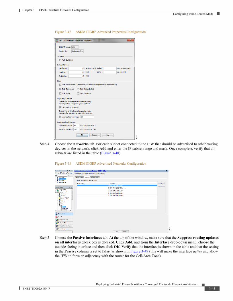
Chapter 3 CPwE Industrial Firewalls ConfigurationConfiguring Inline Routed Mode
Figure 3-47 ASDM EIGRP Advanced Properties Configuration
Step 4 Choose the Networks tab. For each subnet connected to the IFW that should be advertised to other routing devices in the network, click Add and enter the IP subnet range and mask. Once complete, verify that all subnets are listed in the table (Figure 3-48).
Figure 3-48 ASDM EIGRP Advertised Networks Configuration
Step 5 Choose the Passive Interfaces tab. At the top of the window, make sure that the Suppress routing updates on all interfaces check box is checked. Click Add, and from the Interface drop-down menu, choose the outside-facing interface and then click OK. Verify that the interface is shown in the table and that the setting in the Passive column is set to false, as shown in Figure 3-49 (this will make the interface active and allow the IFW to form an adjacency with the router for the Cell/Area Zone).
3-45Deploying Industrial Firewalls within a Converged Plantwide Ethernet Architecture
ENET-TD002A-EN-P

Chapter 3 CPwE Industrial Firewalls ConfigurationConfiguring Inline Routed Mode
Figure 3-49 ASDM EIGRP Passive Interfaces Configuration
Step 6 Click Apply to apply the changes and enable the EIGRP process.
Step 7 Additional configuration is also required on the adjacent routing device (such as the Cell/Area Zone distribution switch) to form the neighborship, exchange routes and be sure that the IFW, as a stub router, only receives a single default route for traffic destined for remote subnets. An example of this CLI configuration is given below for an Industrial Ethernet 5000/Stratix 5410 switch, but it may vary slightly depending on which platform is used in that role.
router eigrp 101 network 10.17.10.0 0.0.0.255 passive-interface default no passive-interface Vlan10!interface Vlan10 ip summary-address eigrp 101 0.0.0.0 0.0.0.0!
The equivalent CLI for this routing configuration is shown below:
router eigrp 101 eigrp stub connected network 10.17.40.0 255.255.255.0 network 10.17.41.0 255.255.255.0 network 10.17.42.0 255.255.255.0 network 10.17.50.0 255.255.255.0 network 10.17.51.0 255.255.255.0 network 10.17.52.0 255.255.255.0 network 10.255.255.64 255.255.255.252 passive-interface default no passive-interface outside!
Access Rule Configuration
All access rule configurations are the same whether the IFW is deployed in transparent or routed mode, so please see Configuring Inline Transparent Mode, page 3-13 for detailed configuration procedures.
3-46Deploying Industrial Firewalls within a Converged Plantwide Ethernet Architecture
ENET-TD002A-EN-P

Chapter 3 CPwE Industrial Firewalls ConfigurationConfiguring Inline Routed Mode
NAT Configuration
To configure NAT (if required) on the IFW, complete the following steps:
Step 1 Click Configuration at the top left and then Firewall at the bottom left. From the Firewall pane, choose NAT Rules.
Step 2 Click Add at the top to create a new NAT rule.
Step 3 Under Match Criteria: Original Packet, leave Source and Destination Interfaces as Any (default) and then click the ellipsis button next to Destination Address to choose the desired outside IP address for the device. If needed, click Add to create a new network object for the outside IP address. After choosing this object and clicking Original Destination Address to place it in the box, click OK.
Step 4 Under Action: Translated Packet, make sure that the Source NAT Type is set to Static and then check the Use one-to-one address translation check box. Choose the ellipsis button next to Destination Address to choose the desired inside (actual) IP address configured on the device. As in the previous step, create the object if necessary, click Translated Destination Address to place it in the box and then click OK.
Step 5 Make sure that the Enable rule check box under Options is checked and that Direction is set to Both. Enter a Description, if desired and then click OK to add the new NAT rule (Figure 3-50).
Figure 3-50 ASDM NAT Rule Addition Window
Step 6 Note that since Both was specified for the rule direction, the corresponding NAT rule for traffic in the opposite direction has automatically been added and grouped with the configured rule. Continue to add other necessary NAT rules using the process from Steps 2-5 and then click Apply at the bottom of the window to apply the changes (Figure 3-51).
3-47Deploying Industrial Firewalls within a Converged Plantwide Ethernet Architecture
ENET-TD002A-EN-P

Chapter 3 CPwE Industrial Firewalls ConfigurationConfiguring Inline Routed Mode
Figure 3-51 ASDM NAT Rules Configuration
The equivalent CLI for this NAT configuration is shown below:
object network CLX_P_NAT host 10.17.50.11 description CLX_P_50_11object network CLX_P_Actual host 10.17.40.11 description CLX_P_40_11object network CLX_E_F_NAT host 10.17.51.11 description CLX E_F NATobject network CLX_E_F_Actual host 10.17.41.11 description CLX E_F_Actualobject network CLX_I_NAT host 10.17.52.11 description CLX_I NATobject network CLX_I_Actual host 10.17.42.11 description CLX_I Actualobject network FLEX_Actual host 10.17.41.12 description Flex I/O Actualobject network FLEX_NAT host 10.17.51.12 description FLEX I/O NATnat (any,any) source static any any destination static CLX_P_NAT CLX_P_Actual net-to-net description CLX_P NATnat (any,any) source static any any destination static CLX_E_F_NAT CLX_E_F_Actual net-to-net description CLX_E,F NATnat (any,any) source static any any destination static CLX_I_NAT CLX_I_Actual net-to-net description CLX_I NATnat (any,any) source static any any destination static FLEX_NAT FLEX_Actual net-to-net
3-48Deploying Industrial Firewalls within a Converged Plantwide Ethernet Architecture
ENET-TD002A-EN-P

Chapter 3 CPwE Industrial Firewalls ConfigurationConfiguring Monitor-only Mode
FirePOWER Configuration
All FirePOWER module configurations are the same whether the IFW is deployed in transparent or routed mode, so please see Configuring Inline Transparent Mode, page 3-13 for detailed configuration procedures.
Configuring Monitor-only ModeThis section describes how to customize the IFW configuration when being deployed in monitor-only mode.
Interface Configuration
Only one interface on the IFW (apart from management) is used when deployed in monitor-only mode. This interface receives all the replicated traffic from the connected switch and sends it directly to the FirePOWER module for processing and inspection. To enable this functionality, the interface must be placed in traffic forwarding mode.
To configure the traffic forwarding interface, complete the following steps:
Step 1 Click Configuration at the top left and then Device Setup at the bottom left. From the Device Setup pane, choose Interface Settings > Interfaces.
Step 2 Choose the connected interface in the list and on the right side, click Edit.
Note A physical interface must be chosen to serve as the traffic forwarding interface. BVIs, VLAN subinterfaces and EtherChannel interfaces are not supported for this role.
Step 3 Make sure that the interface configuration is empty, except for being enabled. Check the Forward traffic to the ASA FirePOWER module for inspection and reporting check box to enable traffic forwarding mode on the interface. Finally, click OK (Figure 3-52).
3-49Deploying Industrial Firewalls within a Converged Plantwide Ethernet Architecture
ENET-TD002A-EN-P

Chapter 3 CPwE Industrial Firewalls ConfigurationConfiguring Central Management
Figure 3-52 ASDM Traffic Forwarding Interface Configuration
Step 4 Click Apply at the bottom of the screen to commit the changes. The equivalent CLI for this configuration is shown below:
interface GigabitEthernet1/1 no nameif no security-level traffic-forward sfr monitor-only!
Note An informational message may be shown when configuring the interface via CLI, indicating that the traffic forwarding mode is only for demonstration purposes and not supported in a production environment. This message can be ignored, as the feature is fully supported.
FirePOWER Module Configuration
All FirePOWER module configurations are the same whether the IFW is placed inline or in monitor-only mode, so please see Configuring Inline Transparent Mode, page 3-13 for detailed configuration procedures.
Configuring Central ManagementThis section describes how to configure and use the FireSIGHT Management Center and Cisco Security Manager (CSM) to manage a large deployment of IFWs.
3-50Deploying Industrial Firewalls within a Converged Plantwide Ethernet Architecture
ENET-TD002A-EN-P

Chapter 3 CPwE Industrial Firewalls ConfigurationConfiguring Central Management
FireSIGHT Management Center
Installation and Setup
The FireSIGHT Management Center can be installed as either a dedicated or virtualized appliance, depending on the deployment:
• For detailed procedures regarding installation and initial setup of a dedicated FireSIGHT Management Center appliance, see the FireSIGHT Installation Guide, Version 5.4.1 at the following URL:
– http://www.cisco.com/c/en/us/td/docs/security/firesight/541/install-guide/FireSIGHT-Installation-Guide.html
• For detailed procedures regarding installation and initial setup of a virtualized FireSIGHT Management Center appliance, see FireSIGHT Virtual Installation Guide Version 5.4.1 at the following URL:
– http://www.cisco.com/c/en/us/td/docs/security/firesight/541/virtual-install-guide/FireSIGHT-Virtual-Installation-Guide.html
Device Registration
For the FirePOWER module of the IFW to be managed by FireSIGHT Management Center, it must first be registered for remote management.
Note When the FirePOWER module is registered with FireSIGHT Management Center, all locally configured policies and intrusion rules will be lost. Be sure to record all settings before registering the device if those same settings will be used within FireSIGHT Management Center.
To register the module with FireSIGHT Management Center, complete the following steps:
Step 1 Click Configuration at the top left and then ASA FirePOWER Configuration at the bottom left. From the ASA FirePOWER Configuration pane, choose Local > Registration.
Step 2 Click Add Manager. Complete the required fields of Management Host (IP address or hostname of the FireSIGHT Management Center instance) and Registration Key (any unique series of alphanumeric characters). Once complete, click Save (Figure 3-53).
3-51Deploying Industrial Firewalls within a Converged Plantwide Ethernet Architecture
ENET-TD002A-EN-P

Chapter 3 CPwE Industrial Firewalls ConfigurationConfiguring Central Management
Figure 3-53 ASDM Remote Manager Configuration
Step 3 Once complete, the Manager will be shown in the Registration window with a status of Pending Registration (Figure 3-54).
Figure 3-54 ASDM Remote Manager Display
Step 4 Access the FireSIGHT Management Center via the web GUI. Click the Devices tab and then Device Management. At the top right, click Add and then choose Add Device from the drop-down menu.
Step 5 In the Host field, enter the management IP address of the FirePOWER module. In the Registration Key field, enter the exact alphanumeric character sequence that was configured in Step 2. If the module should be assigned to a particular organizational group (configured separately), choose it from the Group drop-down menu or choose None. If the module should have a preexisting policy assigned to it after registration, choose it from the Access Control Policy drop-down menu or choose Default Access Control. Finally, check the check boxes next to Protection and Control under Licensing to assign a license for these features to the module and then click Register to add the device (Figure 3-55).
3-52Deploying Industrial Firewalls within a Converged Plantwide Ethernet Architecture
ENET-TD002A-EN-P

Chapter 3 CPwE Industrial Firewalls ConfigurationConfiguring Central Management
Figure 3-55 FireSIGHT Management Center Device Addition Window
Note Make sure that the host IP address corresponds to the management IP address of the FirePOWER module, not to the IFW itself. If the IFW management IP address is entered here, device registration will not succeed.
Note Licenses must be added to FireSIGHT Management Center under System > Licenses before being enabled for a managed device. Otherwise, these licenses will not be applied for that device. The Protection license enables intrusion prevention and detection capabilities on the FirePOWER module, and the Control license enables application and user based parameters for access control policy rules, so both of these licenses must be enabled for full functionality of the FirePOWER module. More information on licensing with FireSIGHT Management Center can be found in FireSIGHT System User Guide Version 5.4.1 at the following URL:
• http://www.cisco.com/c/en/us/td/docs/security/firesight/541/user-guide/FireSIGHT-System-UserGuide-v5401/Licensing.html
Step 6 Adding the device may take several minutes. Once added, the device will be displayed under its configured group or Ungrouped if no group was selected (Figure 3-56).
Figure 3-56 FireSIGHT Management Center Device Management List View
Note Once the FirePOWER module has been registered in FireSIGHT Management Center, it can no longer be configured within ASDM. Only the ASA FirePOWER Status tab will be displayed.
3-53Deploying Industrial Firewalls within a Converged Plantwide Ethernet Architecture
ENET-TD002A-EN-P

Chapter 3 CPwE Industrial Firewalls ConfigurationConfiguring Central Management
FirePOWER Module Configuration
Configuration of the FirePOWER module using the FireSIGHT Management Center is very similar to local configuration within ASDM and has a matching look and feel. However, the user must navigate through a different hierarchical scheme to access these configuration options. Some examples of the most common configuration areas include:
• Access Control Policies—Go to Policies > Access Control
• Intrusion Policies—Go to Policies > Intrusion > Intrusion Policy
• Intrusion Rules—Go to Policies > Intrusion > Rule Editor
Please see the FirePOWER Module Configuration sections earlier in this chapter for detailed configuration procedures.
Cisco Security Manager
Installation and Setup
More information on installation and setup of the Cisco Security Manager can be found in the Installation Guide for Cisco Security Manager 4.10 at the following URL:
• http://www.cisco.com/c/en/us/td/docs/security/security_management/cisco_security_manager/security_manager/410/installation/guide/IG.html
Configuration
More information on configuration and IFW management using the Cisco Security Manager can be found in the User Guide for Cisco Security Manager 4.10 at the following URL:
• http://www.cisco.com/c/en/us/td/docs/security/security_management/cisco_security_manager/security_manager/410/user/guide/CSMUserGuide.html
Note Unlike with FireSIGHT Management Center, IFWs that are centrally managed using Cisco Security Manager can still be configured locally using ASDM if needed.
3-54Deploying Industrial Firewalls within a Converged Plantwide Ethernet Architecture
ENET-TD002A-EN-P

Deploying Industrial Firewalls within a Con
ENET-TD002A-EN-P
C H A P T E R 4
CPwE Industrial Firewalls TroubleshootingThis chapter, which describes how to assess and verify the status of the industrial firewall, includes the following major topics:
• Troubleshooting the ASA, page 4-1
• Troubleshooting the FirePOWER Module, page 4-3
Troubleshooting the ASA
Access Rules
For information on troubleshooting access rules on the IFW, please see Chapter 4 of the Securely Traversing IACS Data Across the Industrial Demilitarized Zone Design and Implementation Guide, found at the following URLs:
• Rockwell Automation site:
– http://literature.rockwellautomation.com/idc/groups/literature/documents/td/enet-td009_-en-p.pdf
• Cisco site:
– http://www.cisco.com/c/en/us/td/docs/solutions/Verticals/CPwE/3-5-1/IDMZ/DIG/CPwE_IDMZ_CVD.html
Connections
The IFW keeps track of connections between endpoints that have been established across the IFW. These connections are identified by their 5-tuple characteristics: source and destination IP address, source and destination port number, and protocol. Once the connection has been permitted to form by the configured access rules, any subsequent communications for that connection are automatically forwarded without being subjected to evaluation against the access rules. In ASDM, the user can view a list of these connections by clicking Monitoring at the top and then choosing Connections in the Properties pane on the left side (Figure 4-1). This information is useful to confirm whether or not two endpoints have successfully established a connection, as well as the port numbers and other parameters of that connection.
4-1verged Plantwide Ethernet Architecture

Chapter 4 CPwE Industrial Firewalls TroubleshootingTroubleshooting the ASA
Figure 4-1 ASDM Connection Monitoring Window
Note If the access rules on the IFW are changed to be more restrictive, any communications already using the established connections that should be blocked by the new rules will continue to be allowed because of the automatic forwarding behavior for established connections. For the new rules to take effect, either the connections must be torn down and reestablished by the endpoints, or the connections must be manually cleared by clicking Clear at the top of the connection list.
Other Information
For other references to troubleshoot the ASA component of the IFW, please see the following URLs:
• ASA 8.3 and Later: Monitor and Troubleshoot Performance Issues at the following URL:
– http://www.cisco.com/c/en/us/support/docs/security/asa-5500-x-series-next-generation-firewalls/113185-asaperformance.html
• ASA 8.3: Establish and Troubleshoot Connectivity Through the Cisco Security Appliance at the following URL:
– http://www.cisco.com/c/en/us/support/docs/security/asa-5500-x-series-next-generation-firewalls/113182-asa83-tshoot-csa-00.html
• ASA 8.2: Packet Flow through an ASA Firewall at the following URL:
– http://www.cisco.com/c/en/us/support/docs/security/asa-5500-x-series-next-generation-firewalls/113396-asa-packet-flow-00.html
• ASA Connection Problems to the Cisco Adaptive Security Device Manager at the following URL:
– http://www.cisco.com/c/en/us/support/docs/security/adaptive-security-device-manager/116403-configure-asdm-00.html
• ASA Network Address Translation Configuration Troubleshooting at the following URL:
– http://www.cisco.com/c/en/us/support/docs/security/asa-5500-x-series-next-generation-firewalls/116388-technote-nat-00.html
• Other topics:
– http://www.cisco.com/c/en/us/support/security/asa-5500-series-next-generation-firewalls/products-tech-notes-list.html
4-2Deploying Industrial Firewalls within a Converged Plantwide Ethernet Architecture
ENET-TD002A-EN-P

Chapter 4 CPwE Industrial Firewalls TroubleshootingTroubleshooting the FirePOWER Module
Troubleshooting the FirePOWER Module
Basic Information
For essential details of the FirePOWER module, such as software version, status, and management IP address, ASDM provides several dashboard-style views from the Home screen. Figure 4-2 shows one example of this summarized information on the ASA FirePOWER Status tab.
Figure 4-2 ASDM ASA FirePOWER Status View
A similar set of details can also be gathered from the CLI using the show module sfr detail command, as shown below:
ISA3K-7# show module sfr detailGetting details from the Service Module, please wait...
Card Type: FirePOWER Services Software ModuleModel: ISA-3000-2C2FHardware version: N/ASerial Number: FOC1940V024Firmware version: N/ASoftware version: 5.4.1.7-18MAC Address Range: 5067.ae2f.a500 to 5067.ae2f.a500App. name: ASA FirePOWERApp. Status: UpApp. Status Desc: Normal OperationApp. version: 5.4.1.7-18Data Plane Status: UpConsole session: ReadyStatus: UpDC addr: No DC ConfiguredMgmt IP addr: 192.168.30.101Mgmt Network mask: 255.255.0.0Mgmt Gateway: 0.0.0.0Mgmt web ports: 443Mgmt TLS enabled: true
Note If ASDM does not show the ASA FirePOWER tabs on the Home screen, or if the CLI command returns an error, the FirePOWER module may not be active or may not have network connectivity via the IFW management port.
4-3Deploying Industrial Firewalls within a Converged Plantwide Ethernet Architecture
ENET-TD002A-EN-P

Chapter 4 CPwE Industrial Firewalls TroubleshootingTroubleshooting the FirePOWER Module
Packet Actions
The show service-policy sfr command can be run from the CLI to track the following data:
• How many packets have been sent to the FirePOWER module for inspection (packet input)
• How many packets have been returned from the module (packet output)
• How many packets have been dropped as a result of inspection policies (drop/reset-drop)
A sample of the output from this command is shown below:
ISA3K-7# show service-policy sfr
Global policy: Service-policy: global_policy Class-map: sfr SFR: card status Up, mode fail-open packet input 6807, packet output 6807, drop 1, reset-drop 1
Event Viewer
The event viewer feature of the FirePOWER module maintains a list of events that are generated when an applied rule (OpenAppID or IPS) is matched by an inspected packet. The generated events can be viewed in several ways, depending on how the module is configured and managed:
• Event viewer:
– Local management using ASDM: Monitoring > ASA FirePOWER Monitoring > Real Time Eventing
– Central management using FireSIGHT Management Center: Analysis > Connections > Events or Analysis > Intrusions > Events
• Syslog server
• SNMP server
• Email notifications (IPS rules only)
The logging target is set according to the access control (OpenAppID) or intrusion (IPS) policy configuration. Regardless of how the events are logged, they contain similar data showing the action taken, timestamp, source and destination IP addresses and port numbers, identified application, and other details. The event viewer option can be customized as needed to include only relevant columns of data for a particular user. Figure 4-3 shows an example of the ASDM event viewer output, while Figure 4-4 shows the FireSIGHT Management Center event viewer output (note that the device IP address is included, since events will be consolidated from multiple managed devices).
4-4Deploying Industrial Firewalls within a Converged Plantwide Ethernet Architecture
ENET-TD002A-EN-P

Chapter 4 CPwE Industrial Firewalls TroubleshootingTroubleshooting the FirePOWER Module
Figure 4-3 ASDM Event Viewer
Figure 4-4 FireSIGHT Management Center Event Viewer
More information on configuring and using the event viewer, as well as external notification options, can be found at the following URLs:
• OpenAppID rules and access control policy logging:
– http://www.cisco.com/c/en/us/td/docs/security/firesight/541/user-guide/FireSIGHT-System-UserGuide-v5401/AC-Connection-Logging.html
• IPS rules and intrusion policy logging:
– http://www.cisco.com/c/en/us/td/docs/security/firesight/541/user-guide/FireSIGHT-System-UserGuide-v5401/Intrusion-Events.html
• External notifications:
– http://www.cisco.com/c/en/us/td/docs/security/firesight/541/user-guide/FireSIGHT-System-UserGuide-v5401/Alerting.html
Note The current FirePOWER implementation may limit the number of events generated for OpenAppID rule matches to a single entry for long-running TCP connections, which are common for devices communicating via CIP. This limitation does not apply to events generated by IPS rule matches. For more details on logging recommendations, please see CPwE Industrial Firewalls Design Considerations
Other Information
For other references to troubleshoot the FirePOWER module within the IFW, please see the following URLs:
• TAC Documents on FirePOWER Service, FireSIGHT System, and AMP
4-5Deploying Industrial Firewalls within a Converged Plantwide Ethernet Architecture
ENET-TD002A-EN-P

Chapter 4 CPwE Industrial Firewalls TroubleshootingTroubleshooting the FirePOWER Module
– http://www.cisco.com/c/en/us/support/docs/security/firesight-management-center/118889-technote-firesight-00.html
• Other topics:
– http://www.cisco.com/c/en/us/support/security/asa-firepower-services/products-tech-notes-list.html
4-6Deploying Industrial Firewalls within a Converged Plantwide Ethernet Architecture
ENET-TD002A-EN-P

Chapter 4 CPwE Industrial Firewalls TroubleshootingTroubleshooting the FirePOWER Module
4-7Deploying Industrial Firewalls within a Converged Plantwide Ethernet Architecture
ENET-TD002A-EN-P

Deploying Industrial Firewalls within a Co
ENET-TD002A-EN-P
A P P E N D I X A
ReferencesThis appendix includes the following major topics:
• Converged Plantwide Ethernet (CPwE), page A-1
• Adaptive Security Device Manager (ASDM), page A-2
• Cisco Security Manager (CSM), page A-2
• FirePOWER Module, page A-2
• FireSIGHT Management Center, page A-3
• Industrial Firewalls (IFW), page A-3
• Other References, page A-4
Converged Plantwide Ethernet (CPwE)• Converged Plantwide Ethernet (CPwE) Design and Implementation Guide:
– Rockwell Automation site: http://literature.rockwellautomation.com/idc/groups/literature/documents/td/enet-td001_-en-p.pdf
– Cisco site: http://www.cisco.com/c/en/us/td/docs/solutions/Verticals/CPwE/CPwE_DIG.html
• Deploying Identity Services within a Converged Plantwide Ethernet Architecture Design and Implementation Guide:
– Rockwell Automation site:
– http://literature.rockwellautomation.com/idc/groups/literature/documents/td/enet-td008_-en-p.pdf
– Cisco site:
– http://www.cisco.com/c/en/us/td/docs/solutions/Verticals/CPwE/3-5-1/ISE/DIG/CPwE_ISE_CVD.html
• Deploying A Resilient Converged Plantwide Ethernet Architecture Design and Implementation Guide:
– Rockwell Automation site:
– http://literature.rockwellautomation.com/idc/groups/literature/documents/td/enet-td010_-en-p.pdf
A-1nverged Plantwide Ethernet Architecture

Appendix A ReferencesAdaptive Security Device Manager (ASDM)
– Cisco site:
– http://www.cisco.com/c/en/us/td/docs/solutions/Verticals/CPwE/REP/CPwE_REP_DG.html
• Securely Traversing IACS Data Across the Industrial Demilitarized Zone Design and Implementation Guide:
– Rockwell Automation site:
– http://literature.rockwellautomation.com/idc/groups/literature/documents/td/enet-td009_-en-p.pdf
– Cisco Site:
– http://www.cisco.com/c/en/us/td/docs/solutions/Verticals/CPwE/3-5-1/IDMZ/DIG/CPwE_IDMZ_CVD.html
Adaptive Security Device Manager (ASDM)• Cisco ASA Series General Operations ASDM Configuration Guide, 7.6:
– http://www.cisco.com/c/en/us/td/docs/security/asa/asa96/asdm76/general/asdm-76-general-config.html
• Cisco ASA Series Firewall ASDM Configuration Guide, 7.6:
– http://www.cisco.com/c/en/us/td/docs/security/asa/asa96/asdm76/firewall/asdm-76-firewall-config.html
Cisco Security Manager (CSM)• Installation Guide for Cisco Security Manager 4.10:
– http://www.cisco.com/c/en/us/td/docs/security/security_management/cisco_security_manager/security_manager/410/installation/guide/IG.html
• User Guide for Cisco Security Manager 4.10:
– http://www.cisco.com/c/en/us/td/docs/security/security_management/cisco_security_manager/security_manager/410/user/guide/CSMUserGuide.html
FirePOWER Module• FireSIGHT System User Guide Version 5.4.1 - Configuring SCADA Preprocessing - Configuring the CIP
Preprocessor:
– http://www.cisco.com/c/en/us/td/docs/security/firesight/541/user-guide/FireSIGHT-System-UserGuide-v5401/NAP-SCADA.html#pgfId-1552845
• ASA FirePOWER Module User Guide, Version 5.4.1 - Getting Started with Access Control Policies:
– http://www.cisco.com/c/en/us/td/docs/security/firesight/541/firepower-module-user-guide/asa-firepower-module-user-guide-v541/AC-Getting-Started.html
• FireSIGHT System User Guide Version 5.4.1 - Limiting Intrusion Event Logging:
– http://www.cisco.com/c/en/us/td/docs/security/firesight/541/user-guide/FireSIGHT-System-UserGuide-v5401/Intrusion-Global-Threshold.html
A-2Deploying Industrial Firewalls within a Converged Plantwide Ethernet Architecture
ENET-TD002A-EN-P

Appendix A ReferencesFireSIGHT Management Center
• ASA FirePOWER Module User Guide, Version 5.4.1 - Getting Started with Intrusion Policies:
– http://www.cisco.com/c/en/us/td/docs/security/firesight/541/firepower-module-user-guide/asa-firepower-module-user-guide-v541/Intrusion-Getting-Started.html
• FireSIGHT System User Guide Version 5.4.1 - Logging Connections in Network Traffic:
– http://www.cisco.com/c/en/us/td/docs/security/firesight/541/user-guide/FireSIGHT-System-UserGuide-v5401/AC-Connection-Logging.html
• FireSIGHT System User Guide Version 5.4.1 - Working with Intrusion Events:
– http://www.cisco.com/c/en/us/td/docs/security/firesight/541/user-guide/FireSIGHT-System-UserGuide-v5401/Intrusion-Events.html
• FireSIGHT System User Guide Version 5.4.1 - Configuring External Alerting:
– http://www.cisco.com/c/en/us/td/docs/security/firesight/541/user-guide/FireSIGHT-System-UserGuide-v5401/Alerting.html
FireSIGHT Management Center• FireSIGHT Installation Guide, Version 5.4.1:
– http://www.cisco.com/c/en/us/td/docs/security/firesight/541/install-guide/FireSIGHT-Installation-Guide.html
• FireSIGHT Virtual Installation Guide Version 5.4.1:
– http://www.cisco.com/c/en/us/td/docs/security/firesight/541/virtual-install-guide/FireSIGHT-Virtual-Installation-Guide.html
• FireSIGHT System User Guide Version 5.4.1 - Licensing the FireSIGHT System:
– http://www.cisco.com/c/en/us/td/docs/security/firesight/541/user-guide/FireSIGHT-System-UserGuide-v5401/Licensing.html
Industrial Firewalls (IFW)• Hardware Installation Guide:
– Allen-Bradley Stratix 5950:
– http://ab.rockwellautomation.com/Networks-and-Communications/Stratix-5950-Security-Appliance#documentation
– Cisco Industrial Security Appliance 3000:
– http://www.cisco.com/c/en/us/td/docs/security/Firewalls/ISA3000/hardware/ISA3000hwinst/initconfig.html
• Cisco ASA Series General Operations ASDM Configuration Guide, 7.6 - AAA and the Local Database:
– http://www.cisco.com/c/en/us/td/docs/security/asa/asa96/asdm76/general/asdm-76-general-config/aaa-local.html
A-3Deploying Industrial Firewalls within a Converged Plantwide Ethernet Architecture
ENET-TD002A-EN-P

Appendix A ReferencesOther References
Other References• NIST Special Publication 800-41 - Guidelines on Firewalls and Firewall Policy:
– http://csrc.nist.gov/publications/nistpubs/800-41-Rev1/sp800-41-rev1.pdf
A-4Deploying Industrial Firewalls within a Converged Plantwide Ethernet Architecture
ENET-TD002A-EN-P

Appendix A ReferencesOther References
A-5Deploying Industrial Firewalls within a Converged Plantwide Ethernet Architecture
ENET-TD002A-EN-P

Deploying Industrial Firewalls within a Co
ENET-TD002A-EN-P
A P P E N D I X B
Test Hardware and SoftwareTable B-1 lists the test hardware and software for the Deploying Industrial Firewalls within a Converged Plantwide Ethernet (CPwE) Architecture DIG.
Table B-1 Test Hardware and Software
Role Product Software Version
Access switch Cisco Industrial Ethernet 2000 Series Switch / Allen-Bradley Stratix 5700 15.2(3)EA
Access switch Cisco Industrial Ethernet 3000 Series Switch / Allen-Bradley Stratix 8000 15.2(3)EA
Access switch Cisco Industrial Ethernet 4000 Series Switch / Allen-Bradley Stratix 5400 15.2(2)EA3
Distribution switch Cisco Industrial Ethernet 5000 Series Switch / Allen-Bradley Stratix 5410 15.2(2)EB2
Distribution switch Catalyst® 3850 16.2.2
Core switch Catalyst 6800 15.2(1)SY1a
Firewall Cisco Industrial Security Appliance 3000
Allen-Bradley Stratix 5950
ISA: 9.6(2)
ASDM: 7.6(2)
FirePOWER module: 5.4.1.7
Firewall Adaptive Security Appliance 5525-X ASA: 9.3(3) ASDM: 7.6(1)
Security FireSIGHT Management Center 5.4.1.8
Security Cisco Security Manager 4.11
Rockwell Software RSLinx Classic 3.80.00 CPR9 SR8
Rockwell Software Studio 5000 Logix Designer® 28.00.02
Rockwell Controller ControlLogix 5570 (1756-L75) 28.011
Rockwell Safety Controller/Partner GuardLogix Safety (1576-L73S) 28.011
Rockwell Ethernet Adapter ControlLogix EtherNet/IP (1756-EN2T/EN2TR) 5.028
Rockwell Controller CompactLogix™ (1769-L36ERM) 28.011
Rockwell Controller CompactLogix (1769-L18ERM) 28.011
Rockwell Adapter FLEX™ I/O EtherNet/IP (1794-AENT) 4.003
Rockwell Adapter POINT™ I/O EtherNet/IP (1734-AENT/AENTR) 3.012
5.012
Rockwell Safety Adapter CompactBlock™ Guard I/O (1791ES-IB8XOBV4) 1.009
B-1nverged Plantwide Ethernet Architecture

Deploying Industrial Firewalls within a Co
ENET-TD002A-EN-P
A P P E N D I X C
CIP Preprocessor GlossaryThis appendix includes the following major topics:
• CIP Generic Application Definitions, page C-1
• CIP Rockwell Automation (Vendor Specific) Application Definitions, page C-1
CIP Generic Application Definitions
CIP Rockwell Automation (Vendor Specific) Application Definitions
Table C-1 CIP Generic Application Definitions
CIP Generic Application Description
CIP Admin ODVA-specified commands that change the state of a device.
CIP Infrastructure ODVA-specified commands that are core functions. For example, Setting up sessions and connections
CIP Read ODVA-specified commands that read data from a device.
CIP Write ODVA-specified commands that write data into a device.
Table C-2 CIP Rockwell Automation (Vendor Specific) Application Definitions
CIP RA (Vendor Specific) Application Description
CIP RA Admin Download Rockwell-specific commands that perform a project download
CIP RA Admin Firmware Update Rockwell-specific commands that perform a firmware update
CIP RA Infrastructure Rockwell-specific commands that are core functions
CIP RA Read Tag Rockwell-specific commands that read tag values from a device
CIP RA Write Tag Rockwell-specific commands that write tag values into a device
C-1nverged Plantwide Ethernet Architecture

Deploying Industrial Firewalls within a Co
ENET-TD002A-EN-P
A P P E N D I X D
GlossaryTable D-1 lists the acronyms and initialisms used in this document.
Table D-1 Acronyms and Initialisms
Term Description
AAA Authentication, Authorization and Accounting
API Application Program Interface
ASA Adaptive Security Appliance
ASDM Adaptive Security Device Manager
BVI Bridged Virtual Interface
CIP™ ODVA Common Industrial Protocol
CLI Command Line Interface
CPwE Converged Plantwide Ethernet
CSM Cisco Security Manager
CVD Cisco Validated Design
DHCP Dynamic Host Configuration Protocol
DIG Design and Implementation Guide
DMZ Demilitarized Zone
DPI Deep Packet Inspection
HMI Human Machine Interface
HPM Health and performance monitoring
IACS Industrial Automation and Control System
ICS Industrial Control System
IDMZ Industrial Demilitarized Zone
IDS Intrusion Detection System
IFW Industrial Firewalls
IIoT Industrial Internet of Things
IP Internet Protocol
IPS Intrusion Prevention System
ISN Initial Sequence Number
IT Informational Technology
NAT Network Address Translation
OEM Original Equipment Manufacturer
D-1nverged Plantwide Ethernet Architecture

Appendix D Glossary
OT Operational Technology
PAC Programmable Automation Controller
PTP Precision Time Protocol
TCP Transmission Control Protocol
UDP User Datagram Protocol
VLAN Virtual Local Area Network
VPN Virtual Private Networks
Table D-1 Acronyms and Initialisms (continued)
Term Description
D-2Deploying Industrial Firewalls within a Converged Plantwide Ethernet Architecture
ENET-TD002A-EN-P

Appendix D Glossary
D-3Deploying Industrial Firewalls within a Converged Plantwide Ethernet Architecture
ENET-TD002A-EN-P

Deploying Industrial Firewalls within a Co
ENET-TD002A-EN-P
A P P E N D I X E
About the Cisco Validated Design (CVD) ProgramConverged Plantwide Ethernet (CPwE) is a collection of tested and validated architectures developed by subject matter authorities at Cisco and Rockwell Automation which follows the Cisco Validated Design (CVD) program.
CVDs provide the foundation for systems design based on common use cases or current engineering system priorities. They incorporate a broad set of technologies, features, and applications to address customer needs. Each one has been comprehensively tested and documented by engineers to enable faster, more reliable, and predictable deployment.
The CVD process is comprehensive and focuses on solving business problems for customers and documenting these solutions. The process consists of the following steps:
1. Requirements are gathered from a broad base of customers to devise a set of use cases that will fulfill these business needs.
2. Network architectures are designed or extended to provide the functionality necessary to enable these use cases, and any missing functionality is relayed back to the appropriate product development team(s).
3. Detailed test plans are developed based on the architecture designs to validate the proposed solution, with an emphasis on feature and platform interaction across the system. These tests generally consist of functionality, resiliency, scale, and performance characterization.
4. All parties contribute to the development of the CVD guide, which covers both design recommendations and implementation of the solution based on the testing outcomes.
For more information about the CVD program, please see Cisco Validated Designs: The Next Frontier at the following URL:
• http://www.cisco.com/c/dam/en/us/td/docs/solutions/CVD/overview/cvd_overview.pdf
E-1nverged Plantwide Ethernet Architecture

Appendix E About the Cisco Validated Design (CVD) Program
Cisco is the worldwide leader in networking that transforms how people connect, communicate and collaborate. Information about Cisco can be found at www.cisco.com. For ongoing news, please go to http://newsroom.cisco.com. Cisco equipment in Europe is supplied by Cisco Systems International BV, a wholly owned subsidiary of Cisco Systems, Inc.
www.cisco.com
Americas HeadquartersCisco Systems, Inc.San Jose, CA
Asia Pacific HeadquartersCisco Systems (USA) Pte. Ltd.Singapore
Europe HeadquartersCisco Systems International BVAmsterdam, The Netherlands
Cisco has more than 200 offices worldwide. Addresses, phone numbers, and fax numbers are listed on the Cisco Website at www.cisco.com/go/offices.
CCDE, CCENT, Cisco Eos, Cisco HealthPresence, the Cisco logo, Cisco Lumin, Cisco Nexus, Cisco StadiumVision, Cisco TelePresence, Cisco WebEx, DCE, and Welcome to the Human Network are trademarks; Changing the Way We Work,Live, Play, and Learn and Cisco Store are service marks; and Access Registrar, Aironet, AsyncOS, Bringing the Meeting To You, Catalyst, CCDA, CCDP, CCIE, CCIP, CCNA, CCNP, CCSP, CCVP, Cisco, the Cisco Certified Internetwork Expertlogo, Cisco IOS, Cisco Press, Cisco Systems, Cisco Systems Capital, the Cisco Systems logo, Cisco Unity, Collaboration Without Limitation, EtherFast, EtherSwitch, Event Center, Fast Step, Follow Me Browsing, FormShare, GigaDrive, Home-Link, Internet Quotient, IOS, iPhone, iQuick Study, IronPort, the IronPort logo, LightStream, Linksys, MediaTone, MeetingPlace, MeetingPlace Chime Sound, MGX, Networkers, Networking Academy, Network Registrar, PCNow, PIX, Power-Panels, ProConnect, ScriptShare, SenderBase, SMARTnet, Spectrum Expert, StackWise, The Fastest Way to Increase Your Internet Quotient, TransPath, WebEx, and the WebEx logo are registered trademarks of Cisco Systems, Inc. and/or itsaffiliates in the United States and certain other countries.
All other trademarks mentioned in this document or website are the property of their respective owners. The use of the word partner does not imply a partnership relationship between Cisco and any other company. (0812R)
Rockwell Automation is a leading provider of power, control and information solutions that enable customers to get products to market faster, reduce their total cost of ownership, better utilize plant assets, and minimize risks in their manufacturing environments.
www.rockwellautomation.com
Americas:Rockwell Automation1201 South Second Street Milwaukee, WI 53204-2496 USA Tel: (1) 414.382.2000, Fax: (1) 414.382.4444
Asia Pacific:Rockwell AutomationLevel 14, Core F, Cyberport 3 100 Cyberport Road, Hong Kong Tel: (852) 2887 4788, Fax: (852) 2508 1846
Europe/Middle East/Africa: Rockwell AutomationVorstlaan/Boulevard du Souverain 36 1170 Brussels, Belgium Tel: (32) 2 663 0600, Fax: (32) 2 663 0640
Allen-Bradley, CompactBlock, CompactLogix, ControlLogix, FLEX, Guard I/O, GuardLogix, Point I/O, RSLinx, Stratix, FactoryTalk, Studio 5000 Logix Designer and Rockwell Automation are trademarks of Rockwell Automation, Inc.CIP and EtherNet/IP are trademarks of ODVA, Inc.
© 2016 Cisco Systems, Inc. and Rockwell Automation, Inc. All rights reserved.
Publication ENET-TD002A-EN-P December 2016


