
Deployable polyhedron mechanisms constructed by connecting ... · Deployable polyhedron mechanisms...
17
1 Deployable polyhedron mechanisms constructed by connecting spatial single-loop linkages of different types and/or in different sizes using S joints Jieyu Wang, Xianwen Kong * School of Engineering and Physical Sciences, Heriot-Watt University, Edinburgh EH14 4AS UK [email protected] and [email protected] Abstract This paper deals with the construction of deployable polyhedron mechanisms (DPMs) by connecting spatial single-loop linkages of different types and/or in different sizes. Linkages consisted of symmetric spatial triad units, including Bricard linkages, 8R (revolute joint) linkages and 10R linkages, are adopted as faces to form polyhedrons. These mechanisms exhibit single-DOF deployable motion and can be deployed through two ways. Several mechanisms based on 8R/10R linkages have multiple modes and can switch modes through transition configurations. Three types of DPMs are addressed: the first type is assembled using distinct types of linkages; the second type is constructed by connecting the same type of linkages in different sizes; the third type has multiple layers composed of the first two types. Keywords Deployable mechanisms, multiple motion modes, polyhedron mechanisms, single-loop linkage, variable-DOF 1. Introduction A number of deployable mechanisms (DMs) have been proposed due to their ability to change the shapes and sizes when encountering different environments and tasks. For example, Chen [1-2] discussed a family of foldable closed-loop over-constrained spatial mechanisms, whose mobility analysis was discussed in literatures such as [3-4]. These mechanisms have one degree-of-freedom (DOF) and can spread onto a plane or fold into a bundle. By inserting planar mechanisms into the faces or edges of polyhedrons, or connecting deployable units, deployable polyhedron mechanisms (DPMs) are obtained in [5-10]. Other types of deployable mechanisms, such as those presented in [11,12], are out of the scope of this paper. Meanwhile, reconfigurable deployable mechanisms were investigated during the past decades. A reconfigurable and deployable mechanism constructed using 1-DOF mechanisms and has four assembly modes was introduced for a canopy [13]. Using variable revolute (R) joint, a group of reconfigurable and deployable mechanisms was set forth by Wei [14]. In [15], a reconfigurable element was presented and used as modules to design mechanisms. The mechanisms can switch modes between the Hoberman sphere motion mode and the radially reciprocating motion mode. A 16-bar mechanism that can transform between 1-DOF spherical linkage mode and 1-DOF planar linkage mode by folding or spreading was proposed in [16]. Kong [17] analyzed a parallel mechanism (PM) with multiple motion modes based on deployable Bricard linkage upper platform. A reconfigurable mechanism which can be spread onto a plane and further folded to a bundle was designed in [18]. A family of foldable eight-bar linkages that have multiple modes is discussed in [19]. * Corresponding author: Xianwen Kong, School of Engineering and Physical Sciences, Heriot-Watt University, Edinburgh, EH14 4AS UK, [email protected]
Transcript of Deployable polyhedron mechanisms constructed by connecting ... · Deployable polyhedron mechanisms...
1
Deployable polyhedron mechanisms constructed by
connecting spatial single-loop linkages of different types
and/or in different sizes using S joints
Jieyu Wang, Xianwen Kong* School of Engineering and Physical Sciences, Heriot-Watt University, Edinburgh EH14 4AS UK
[email protected] and [email protected]
Abstract
This paper deals with the construction of deployable polyhedron mechanisms (DPMs) by connecting spatial single-loop linkages of different types and/or in different sizes. Linkages consisted of
symmetric spatial triad units, including Bricard linkages, 8R (revolute joint) linkages and 10R
linkages, are adopted as faces to form polyhedrons. These mechanisms exhibit single-DOF
deployable motion and can be deployed through two ways. Several mechanisms based on 8R/10R
linkages have multiple modes and can switch modes through transition configurations. Three types of DPMs are addressed: the first type is assembled using distinct types of linkages; the second type
is constructed by connecting the same type of linkages in different sizes; the third type has multiple
layers composed of the first two types.
Keywords
Deployable mechanisms, multiple motion modes, polyhedron mechanisms, single-loop linkage,
variable-DOF
1. Introduction
A number of deployable mechanisms (DMs) have been proposed due to their ability to change the
shapes and sizes when encountering different environments and tasks. For example, Chen [1-2]
discussed a family of foldable closed-loop over-constrained spatial mechanisms, whose mobility
analysis was discussed in literatures such as [3-4]. These mechanisms have one degree-of-freedom
(DOF) and can spread onto a plane or fold into a bundle. By inserting planar mechanisms into the
faces or edges of polyhedrons, or connecting deployable units, deployable polyhedron mechanisms
(DPMs) are obtained in [5-10]. Other types of deployable mechanisms, such as those presented in
[11,12], are out of the scope of this paper.
Meanwhile, reconfigurable deployable mechanisms were investigated during the past decades. A
reconfigurable and deployable mechanism constructed using 1-DOF mechanisms and has four
assembly modes was introduced for a canopy [13]. Using variable revolute (R) joint, a group of
reconfigurable and deployable mechanisms was set forth by Wei [14]. In [15], a reconfigurable
element was presented and used as modules to design mechanisms. The mechanisms can switch
modes between the Hoberman sphere motion mode and the radially reciprocating motion mode. A
16-bar mechanism that can transform between 1-DOF spherical linkage mode and 1-DOF planar
linkage mode by folding or spreading was proposed in [16]. Kong [17] analyzed a parallel
mechanism (PM) with multiple motion modes based on deployable Bricard linkage upper platform.
A reconfigurable mechanism which can be spread onto a plane and further folded to a bundle was
designed in [18]. A family of foldable eight-bar linkages that have multiple modes is discussed in
[19].
* Corresponding author: Xianwen Kong, School of Engineering and Physical Sciences, Heriot-Watt
University, Edinburgh, EH14 4AS UK, [email protected]
Xianwen Kong
Typewritten Text
© <2018>. This manuscript version is made available under the CC-BY-NC-ND 4.0 license http://creativecommons.org/licenses/by-nc-nd/4.0
Xianwen Kong
Typewritten Text
https://doi.org/10.1016/j.mechmachtheory.2018.03.002
Xianwen Kong
Typewritten Text
Jieyu Wang, Xianwen Kong, Deployable polyhedron mechanisms constructed by connecting spatial single-loop linkages of different types and/or in different sizes using S joints. Mechanism and Machine Theory, Volume 124, June 2018, Pages 211–225
2
In [20], we proposed a general method to design deployable PMs and loop coupled mechanisms
(LCMs) using identical loops. Based on the work in [20], this paper will deal with the construction
of DPMs with distinct types of loops or the same type of loops in different sizes. DPMs with multiple
layers will also be presented. This paper together with reference [20] have presented a systematic
approach to the construction of a family of deployable mechanisms by connecting single-loop
mechanisms composed of symmetric spatial triads using S joints. The mechanisms obtained are
overconstrained. They have multiple motion modes and can switch modes through transition
positions.
This paper is organized as follows: Section 2 introduces the single-loop mechanisms and the
DPMs constructed by two distinct types of linkages are presented in Section 3. DPMs based on the
linkages with the same type but different parameters are provided in Section 4 and the multiple-
layer DPMs are assembled in Section 5. Finally, conclusions are drawn.
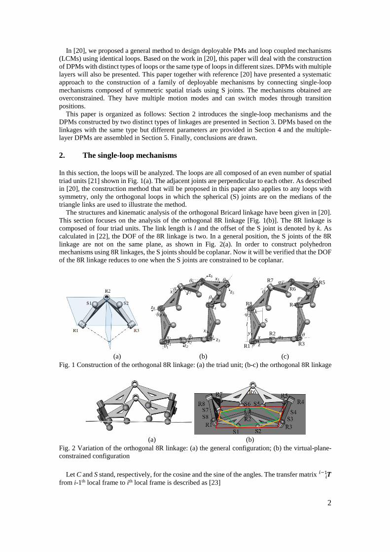
2. The single-loop mechanisms
In this section, the loops will be analyzed. The loops are all composed of an even number of spatial
triad units [21] shown in Fig. 1(a). The adjacent joints are perpendicular to each other. As described
in [20], the construction method that will be proposed in this paper also applies to any loops with
symmetry, only the orthogonal loops in which the spherical (S) joints are on the medians of the
triangle links are used to illustrate the method.
The structures and kinematic analysis of the orthogonal Bricard linkage have been given in [20].
This section focuses on the analysis of the orthogonal 8R linkage [Fig. 1(b)]. The 8R linkage is
composed of four triad units. The link length is l and the offset of the S joint is denoted by k. As
calculated in [22], the DOF of the 8R linkage is two. In a general position, the S joints of the 8R
linkage are not on the same plane, as shown in Fig. 2(a). In order to construct polyhedron
mechanisms using 8R linkages, the S joints should be coplanar. Now it will be verified that the DOF
of the 8R linkage reduces to one when the S joints are constrained to be coplanar.
z1
x1x2
z2
x3
z3
x4
z4
x5
z5
x6
z6
x7 z7
x8
z8
θ1
θ2θ3
θ4
θ6
θ7
θ8
θ5
l
R1
R2
R3
R4
R5
R6
S
k
R7
R8
θ
φ1θ
φ2
θ
θ
φ2
φ1
z
xy
(a) (b) (c)
Fig. 1 Construction of the orthogonal 8R linkage: (a) the triad unit; (b-c) the orthogonal 8R linkage
(a) (b)
Fig. 2 Variation of the orthogonal 8R linkage: (a) the general configuration; (b) the virtual-plane-
constrained configuration
Let C and S stand, respectively, for the cosine and the sine of the angles. The transfer matrix 𝑻𝑖𝑖−1
from i-1th local frame to ith local frame is described as [23]
3
𝑻 = [
𝐶𝜃𝑖
𝐶𝛼𝑖−1𝑆𝜃𝑖
𝑆𝛼𝑖−1𝑆𝜃𝑖
0
−𝑆𝜃𝑖
𝐶𝛼𝑖−1𝐶𝜃𝑖
𝑆𝛼𝑖−1𝐶𝜃𝑖
0
0−𝑆𝛼𝑖−1
𝐶𝛼𝑖−1
0
𝑎𝑖−1
−𝑑𝑖𝑆𝛼𝑖−1
𝑑𝑖𝐶𝛼𝑖−1
1
]𝑖𝑖−1 (1)
where
𝑎0 = 𝑎1 = 𝑎2 = 𝑎3 = 𝑎4 = 𝑎5 = 𝑎6 = 𝑎7 = 𝑙 (2a)
𝛼0 = 𝛼2 = 𝛼4 = 𝛼6 = 270𝑜 (2b)
𝛼1 = 𝛼3 = 𝛼5 = 𝛼7 = 90𝑜 (2c)
𝑑1 = 𝑑2 = 𝑑3 = 𝑑4 = 𝑑5 = 𝑑6 = 𝑑7 = 𝑑8 = 0 (2d)
𝜃1 = 𝜃5 = 𝜃 (2e)
𝜃3 = 𝜃7 = 𝜃′ (2f)
𝜃2 = 𝜃6 = 𝜑1 (2g)
𝜃4 = 𝜃8 = 𝜑2 (2h)
In the deployable mode, suppose that 𝜃′ = 𝜃, for the sake of conciseness [Fig.1(c)]. φ1 = φ2 if the
DOF of the virtual-plane-constrained 8R linkage is one, similar to the Bricard linkage. Otherwise,
the DOF is still two. The position vectors of the centers of the S joints with respect to the local
coordinate frames are
𝑺𝒊𝒊 = {
{𝑙/2 0 𝑘}𝑇 for 𝑖 = 1, 3, 5 and 7
{𝑙/2 𝑘 0}𝑇 for 𝑖 = 2, 4, 6 and 8 (3)
Link 1 is fixed on the ground, and the global coordinate frame is attached to the centre of R1. The
position vectors of the centres of the S joints in the global coordinate frame can be calculated as
{𝑺𝟐
1} = 𝑻 { 𝑺𝟐
𝟐
1}2
1 = {
𝑙 + 𝑙𝐶𝜑1/2 − 𝑘𝑆𝜑1
0 𝑘𝐶𝜑1 + 𝑙𝑆𝜑1/2
1
} (4)
{𝑺𝟑
1} = 𝑻 𝑻 { 𝑺𝟑
𝟑
1} =3
221 {
𝑙 + 𝑙𝐶𝜑1 − 𝑘𝑆𝜑1 + 𝑙𝐶𝜃𝐶𝜑1/2 𝑙𝑆𝜃/2
𝑘𝐶𝜑1 + 𝑙𝑆𝜑1 + 𝑙𝐶𝜃𝑆𝜑1/21
} (5)
{𝑺𝟒
1} = 𝑻 𝑻 𝑻4
332
21 { 𝑺𝟒
𝟒
1} = {𝑆4𝑥 𝑆𝜃[𝑙(2 + 𝐶𝜑2) − 2𝑘𝑆𝜑2]/2 𝑆4𝑧 1}𝑇 (6)
where
𝑆4𝑥 = 𝑙– 𝑆𝜑1(2𝑘𝐶𝜑2 + 𝑙𝑆𝜑2)/2 + 𝐶𝜑1[𝑙 + 𝐶𝜃(𝑙 + 𝑙𝐶𝜑2/2 − 𝑘𝑆𝜑2)] 𝑆4𝑧 = 𝐶𝜑1(𝑘𝐶𝜑2 + 𝑙𝑆𝜑2/2) + 𝑆𝜑1{2𝑙 + 𝐶𝜃[𝑙(2 + 𝐶𝜑2) − 2𝑘𝑆𝜑2]}/2
{𝑺𝟓
1} = 𝑻 𝑻 𝑻 𝑻5
443
32
21 { 𝑺𝟓
𝟓
1} = {𝑆5𝑥 𝑆𝜃[𝑙(2 + 𝐶𝜃)(1 + 𝐶𝜑2) − 2𝑘𝑆𝜑2]/2 𝑆5𝑧 1}𝑇 (7)
where
𝑆5𝑥 = 𝑙 + 2𝑙𝐶4(𝜃/2)𝐶𝜑1 + {𝐶𝜑2[𝑙𝐶𝜃(2 + 𝐶𝜃)𝐶𝜑1 − 2𝑘𝑆𝜑1]−[2𝑘𝐶𝜃𝐶𝜑1 + 𝑙(2 + 𝐶𝜃)𝑆𝜑1]𝑆𝜑2}/2
𝑆5𝑧 = {𝐶𝜑1[2𝑘𝐶𝜑2 + 𝑙(2 + 𝐶𝜃)𝑆𝜑2] + 𝑆𝜑1{4𝑙𝐶4(𝜃/2) + 𝐶𝜃[𝑙(2 + 𝐶𝜃)𝐶𝜑2 − 2𝑘𝑆𝜑2]}}/2
The normal vector to the plane defined by joint centres of S1, S2 and S3 is obtained as
𝑵 = (𝑺𝟐 − 𝑺𝟏) × (𝑺𝟑 − 𝑺𝟐) = {
−𝑙𝑆𝜃[2𝑘(−1 + 𝐶𝜑1) + 𝑙𝑆𝜑1]/4−𝑙(1 + 𝐶𝜃)[2𝑘(−1 + 𝐶𝜑1) + 𝑙𝑆𝜑1]/4
𝑙𝑆𝜃(𝑙 + 𝑙𝐶𝜑1 − 2𝑘𝑆𝜑1)/4} (8)
The equation of the plane is
𝑁𝑥(𝑥 − 𝑙/2) + 𝑁𝑦𝑦 + 𝑁𝑧(𝑧 − 𝑘) = 0 (9)
The condition that the joint centre of S4 is on the plane defined by S1, S2 and S3 is
𝑁𝑥(𝑆4𝑥 − 𝑙/2) + 𝑁𝑦𝑆4𝑦 + 𝑁𝑧(𝑆4𝑧 − 𝑘) = −1
2𝑙𝑆𝜃[𝑙𝐶
𝜑1
2− 2𝑘𝑆
𝜑1
2]𝑆
𝜑1−𝜑2
2[𝑙𝐶
𝜑2
2− 2𝑘𝑆
𝜑2
2] = 0
(10) which leads to
𝜑2 = 𝜑1 or (11)
𝜑2 = 2tan−1(𝑙/2𝑘) (12)
When 𝜑2 = 2tan−1(𝑙/2𝑘), S3 and S4 are concentric, S5 is on the plane requires S1 and S2 to be
also concentric. In this case, 𝜑1 is also equal to 2tan−1(𝑙/2𝑘) and the linkage is in spherical 4R
4
linkage mode [20]. Substituting the position vectors of S5, S6, S7 and S8 into Eq. (9), it is verified
that all the S joints are on the same plane when 𝜑2 = 𝜑1. Hence, 𝜑2 = 𝜑1 is the unique solution.
The 8R linkage is a single-loop mechanism, the product of the transfer matrices equals the identity
matrix, which means
𝑻 𝑻 𝑻43
32
21 𝑻 𝑻 𝑻 𝑻 𝑻 = 𝑰1
887
76
65
54 (13)
Substituting Eqs. (1), (2) and (11) into Eq. (13), φ1 (φ1 = φ2) can be represented by θ as
𝜑2 = 𝜑1 = arccos (1−𝐶𝜃
𝐶𝜃+1) (14)
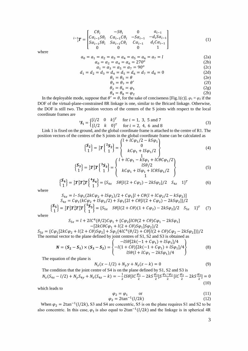
The results show that the virtual-plane-constrained 8R linkage has one DOF, the same as Bricard
linkage. When four spheres are constrained on the same plane, assume that the center of S1 are fixed
on the plane, S3 has one translational DOF on the plane and S5 and S7 have two translational DOFs
on the plane [Fig. 3(a)]. The DOF of the linkage can be calculated using the conventional formula
for DOF (see [24, 25] for example) as
𝑀 = 6(𝑞 − 𝑝) + ∑ 𝑓𝑖𝑝𝑖=1 = 6(8 − 12) + 8 + 3 + 4 + 5 × 2 = 1 (15)
where M, q, p, and fi represent the mobility, the number of links, the number of joints and the
freedom of the ith joint.
If s more S joints are constrained to be on the plane [Fig. 3(b)], the DOF of the virtual-plane-
constrained 8R linkage obtained using the conventional formula for DOF become
𝑀 = 6(𝑞 − 𝑝) + ∑ 𝑓𝑖𝑝𝑖=1 = 6 × (8 − 12 − 𝑠) + 8 + 3 + 4 + 5 × (2 + 𝑠) = 1 − 𝑠 (16)
However, the DOF of the linkage is in fact still one due to the symmetry characteristics of the
linkage. Therefore, the virtual-plane-constrained 8R linkage with more than four S joints is
overconstrained.
(a) (b)
Fig. 3 Sketch of the virtual-plane-constrained orthogonal 8R linkage: (a) four spheres are
constrained on the plane; (b) five spheres are constrained on the plane
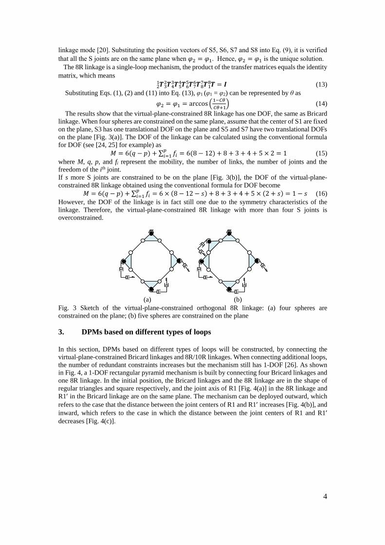
3. DPMs based on different types of loops
In this section, DPMs based on different types of loops will be constructed, by connecting the
virtual-plane-constrained Bricard linkages and 8R/10R linkages. When connecting additional loops,
the number of redundant constraints increases but the mechanism still has 1-DOF [26]. As shown
in Fig. 4, a 1-DOF rectangular pyramid mechanism is built by connecting four Bricard linkages and
one 8R linkage. In the initial position, the Bricard linkages and the 8R linkage are in the shape of
regular triangles and square respectively, and the joint axis of R1 [Fig. 4(a)] in the 8R linkage and
R1’ in the Bricard linkage are on the same plane. The mechanism can be deployed outward, which
refers to the case that the distance between the joint centers of R1 and R1’ increases [Fig. 4(b)], and
inward, which refers to the case in which the distance between the joint centers of R1 and R1’ decreases [Fig. 4(c)].
5
(a) (b) (c)
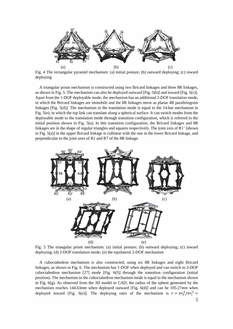
Fig. 4 The rectangular pyramid mechanism: (a) initial posture; (b) outward deploying; (c) inward
deploying
A triangular prism mechanism is constructed using two Bricard linkages and three 8R linkages,
as shown in Fig. 5. The mechanism can also be deployed outward [Fig. 5(b)] and inward [Fig. 5(c)].
Apart from the 1-DOF deployable mode, the mechanism has an additional 2-DOF translation mode,
in which the Bricard linkages are immobile and the 8R linkages move as planar 4R parallelogram
linkages [Fig. 5(d)]. The mechanism in the translation mode is equal to the 14-bar mechanism in
Fig. 5(e), in which the top link can translate along a spherical surface. It can switch modes from the
deployable mode to the translation mode through transition configuration, which is referred to the
initial position shown in Fig. 5(a). In this transition configuration, the Bricard linkages and 8R
linkages are in the shape of regular triangles and squares respectively. The joint axis of R1’ [shown
in Fig. 5(a)] in the upper Bricard linkage is collinear with the one in the lower Bricard linkage, and
perpendicular to the joint axes of R1 and R7 of the 8R linkage.
(a) (b) (c)
(d) (e)
Fig. 5 The triangular prism mechanism: (a) initial posture; (b) outward deploying; (c) inward
deploying; (d) 2-DOF translation mode; (e) the equilateral 2-DOF mechanism
A cuboctahedron mechanism is also constructed, using six 8R linkages and eight Bricard
linkages, as shown in Fig. 6. The mechanism has 1-DOF when deployed and can switch to 3-DOF
cuboctahedron mechanism [27] mode [Fig. 6(f)] through the transition configuration (initial
position). The mechanism in the cuboctahedron mechanism mode is equal to the mechanism shown
in Fig. 6(g). As observed from the 3D model in CAD, the radius of the sphere generated by the
mechanism reaches 144.63mm when deployed outward [Fig. 6(d)] and can be 105.27mm when
deployed inward [Fig. 6(e)]. The deploying ratio of the mechanism is 𝑟 = 𝜋𝑟𝑜3/𝜋𝑟𝑖
3 =
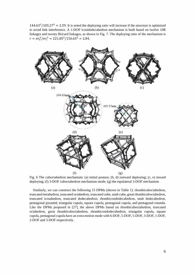
6
144.633/105.273 = 2.59. It is noted the deploying ratio will increase if the structure is optimized
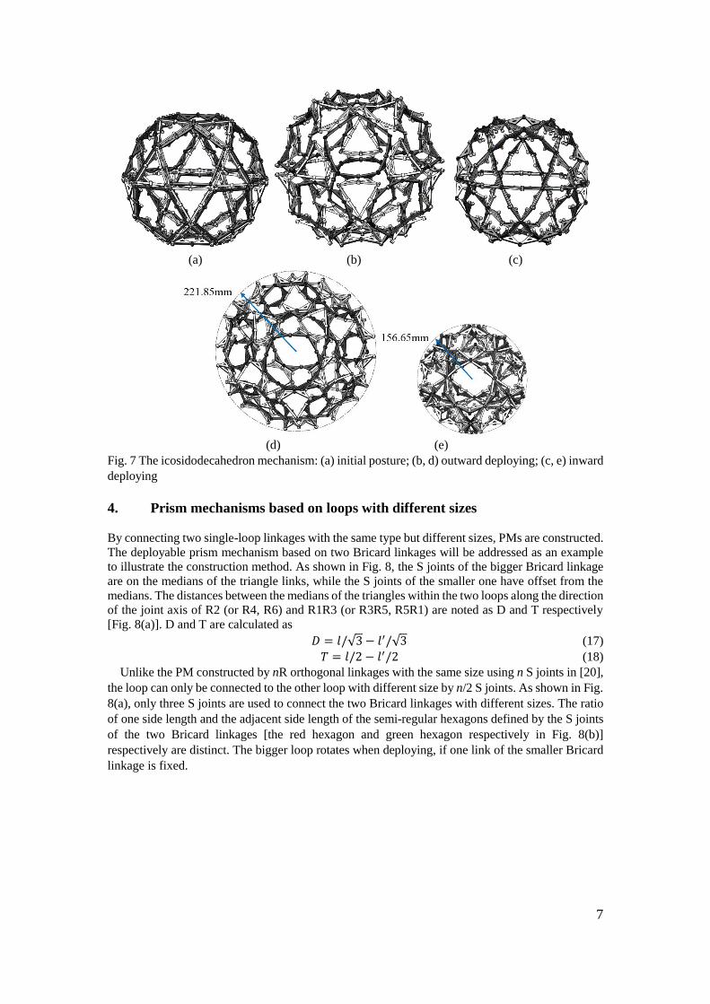
to avoid link interference. A 1-DOF icosidodecahedron mechanism is built based on twelve 10R
linkages and twenty Bricard linkages, as shown in Fig. 7. The deploying ratio of the mechanism is
𝑟 = 𝜋𝑟𝑜3/𝜋𝑟𝑖
3 = 221.853/156.653 = 2.84.
(a) (b) (c)
(d) (e)
(f) (g)
Fig. 6 The cuboctahedron mechanism: (a) initial posture; (b, d) outward deploying; (c, e) inward
deploying; (f) 3-DOF cuboctahedron mechanism mode; (g) the equilateral 3-DOF mechanism
Similarly, we can construct the following 15 DPMs (shown in Table 1): rhombicuboctahedron,
truncated tetrahedron, truncated octahedron, truncated cube, snub cube, great rhombicuboctahedron,
truncated icosahedron, truncated dodecahedron, rhombicosidodecahedron, snub dodecahedron,
pentagonal pyramid, triangular cupola, square cupola, pentagonal cupola, and pentagonal rotunda.
Like the DPMs proposed in [27], the above DPMs based on rhombicuboctahedron, truncated
octahedron, great rhombicuboctahedron, rhombicosidodecahedron, triangular cupola, square
cupola, pentagonal cupola have an extra motion mode with 6-DOF, 5-DOF, 5-DOF, 3-DOF, 1-DOF,
2-DOF and 3-DOF respectively.
7
(a) (b) (c)
(d) (e)
Fig. 7 The icosidodecahedron mechanism: (a) initial posture; (b, d) outward deploying; (c, e) inward
deploying
4. Prism mechanisms based on loops with different sizes
By connecting two single-loop linkages with the same type but different sizes, PMs are constructed.
The deployable prism mechanism based on two Bricard linkages will be addressed as an example
to illustrate the construction method. As shown in Fig. 8, the S joints of the bigger Bricard linkage
are on the medians of the triangle links, while the S joints of the smaller one have offset from the
medians. The distances between the medians of the triangles within the two loops along the direction
of the joint axis of R2 (or R4, R6) and R1R3 (or R3R5, R5R1) are noted as D and T respectively
[Fig. 8(a)]. D and T are calculated as
𝐷 = 𝑙/√3 − 𝑙′/√3 (17)
𝑇 = 𝑙/2 − 𝑙′/2 (18)
Unlike the PM constructed by nR orthogonal linkages with the same size using n S joints in [20],
the loop can only be connected to the other loop with different size by n/2 S joints. As shown in Fig.
8(a), only three S joints are used to connect the two Bricard linkages with different sizes. The ratio
of one side length and the adjacent side length of the semi-regular hexagons defined by the S joints
of the two Bricard linkages [the red hexagon and green hexagon respectively in Fig. 8(b)]
respectively are distinct. The bigger loop rotates when deploying, if one link of the smaller Bricard
linkage is fixed.
8
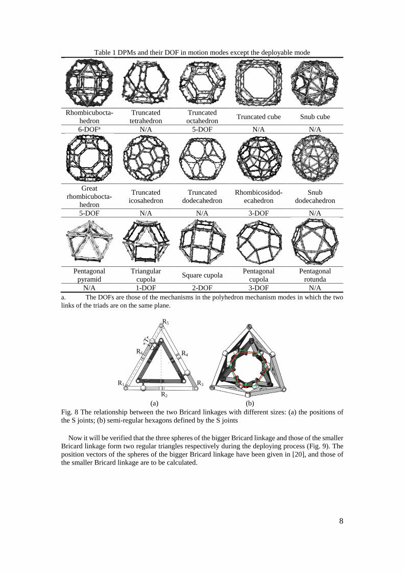
Table 1 DPMs and their DOF in motion modes except the deployable mode
Rhombicubocta-
hedron
Truncated
tetrahedron
Truncated
octahedron Truncated cube Snub cube
6-DOFa N/A 5-DOF N/A N/A
Great
rhombicubocta-
hedron
Truncated
icosahedron
Truncated
dodecahedron
Rhombicosidod-
ecahedron
Snub
dodecahedron
5-DOF N/A N/A 3-DOF N/A
Pentagonal
pyramid
Triangular
cupola Square cupola
Pentagonal
cupola
Pentagonal
rotunda
N/A 1-DOF 2-DOF 3-DOF N/A
a. The DOFs are those of the mechanisms in the polyhedron mechanism modes in which the two
links of the triads are on the same plane.
R3R1
R2
R4
R5
R6
(a) (b)
Fig. 8 The relationship between the two Bricard linkages with different sizes: (a) the positions of
the S joints; (b) semi-regular hexagons defined by the S joints
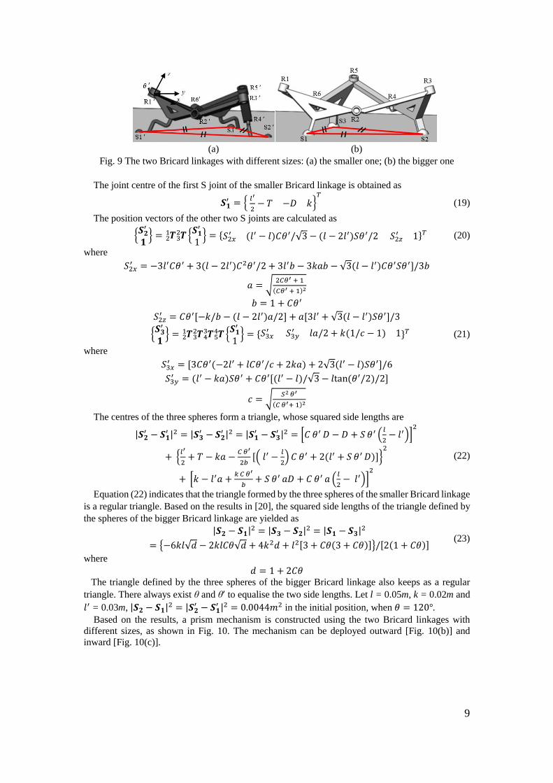
Now it will be verified that the three spheres of the bigger Bricard linkage and those of the smaller
Bricard linkage form two regular triangles respectively during the deploying process (Fig. 9). The
position vectors of the spheres of the bigger Bricard linkage have been given in [20], and those of
the smaller Bricard linkage are to be calculated.
9
(a) (b)
Fig. 9 The two Bricard linkages with different sizes: (a) the smaller one; (b) the bigger one
The joint centre of the first S joint of the smaller Bricard linkage is obtained as
𝑺𝟏′ = {
𝑙′
2− 𝑇 −𝐷 𝑘}
𝑇
(19)
The position vectors of the other two S joints are calculated as
{𝑺𝟐
′
𝟏} = 𝑻 𝑻 {
𝑺𝟏′
1} =3
221 {𝑆2𝑥
′ (𝑙′ − 𝑙)𝐶𝜃′/√3 − (𝑙 − 2𝑙′)𝑆𝜃′/2 𝑆2𝑧′ 1}𝑇 (20)
where
𝑆2𝑥′ = −3𝑙′𝐶𝜃′ + 3(𝑙 − 2𝑙′)𝐶2𝜃′/2 + 3𝑙′𝑏 − 3𝑘𝑎𝑏 − √3(𝑙 − 𝑙′)𝐶𝜃′𝑆𝜃′]/3𝑏
𝑎 = √2𝐶𝜃′ + 1
(𝐶𝜃′ + 1)2
𝑏 = 1 + 𝐶𝜃′
𝑆2𝑧′ = 𝐶𝜃′[−𝑘/𝑏 − (𝑙 − 2𝑙′)𝑎/2] + 𝑎[3𝑙′ + √3(𝑙 − 𝑙′)𝑆𝜃′]/3
{𝑺𝟑
′
𝟏} = 𝑻 𝑻 𝑻 𝑻5
443
32
21 {
𝑺𝟏′
1} = {𝑆3𝑥
′ 𝑆3𝑦′ 𝑙𝑎/2 + 𝑘(1/𝑐 − 1) 1}𝑇 (21)
where
𝑆3𝑥′ = [3𝐶𝜃′(−2𝑙′ + 𝑙𝐶𝜃′/𝑐 + 2𝑘𝑎) + 2√3(𝑙′ − 𝑙)𝑆𝜃′]/6
𝑆3𝑦′ = (𝑙′ − 𝑘𝑎)𝑆𝜃′ + 𝐶𝜃′[(𝑙′ − 𝑙)/√3 − 𝑙tan(𝜃′/2)/2]
𝑐 = √𝑆2 𝜃′
(𝐶 𝜃′+ 1)2
The centres of the three spheres form a triangle, whose squared side lengths are
|𝑺𝟐′ − 𝑺𝟏
′ |2 = |𝑺𝟑′ − 𝑺𝟐
′ |2 = |𝑺𝟏′ − 𝑺𝟑
′ |2 = [𝐶 𝜃′ 𝐷 − 𝐷 + 𝑆 𝜃′ (𝑙
2− 𝑙′)]
2
+ {𝑙′
2+ 𝑇 − 𝑘𝑎 −
𝐶 𝜃′
2𝑏[( 𝑙′ −
𝑙
2) 𝐶 𝜃′ + 2(𝑙′ + 𝑆 𝜃′ 𝐷)]}
2
+ [𝑘 − 𝑙′𝑎 +𝑘 𝐶 𝜃′
𝑏+ 𝑆 𝜃′ 𝑎𝐷 + 𝐶 𝜃′ 𝑎 (
𝑙
2− 𝑙′)]
2
(22)
Equation (22) indicates that the triangle formed by the three spheres of the smaller Bricard linkage
is a regular triangle. Based on the results in [20], the squared side lengths of the triangle defined by
the spheres of the bigger Bricard linkage are yielded as
|𝑺𝟐 − 𝑺𝟏|2 = |𝑺𝟑 − 𝑺𝟐|2 = |𝑺𝟏 − 𝑺𝟑|2
= {−6𝑘𝑙√𝑑 − 2𝑘𝑙𝐶𝜃√𝑑 + 4𝑘2𝑑 + 𝑙2[3 + 𝐶𝜃(3 + 𝐶𝜃)]}/[2(1 + 𝐶𝜃)] (23)
where
𝑑 = 1 + 2𝐶𝜃
The triangle defined by the three spheres of the bigger Bricard linkage also keeps as a regular
triangle. There always exist θ and θ’ to equalise the two side lengths. Let l = 0.05m, k = 0.02m and
𝑙′ = 0.03m, |𝑺𝟐 − 𝑺𝟏|2 = |𝑺𝟐′ − 𝑺𝟏
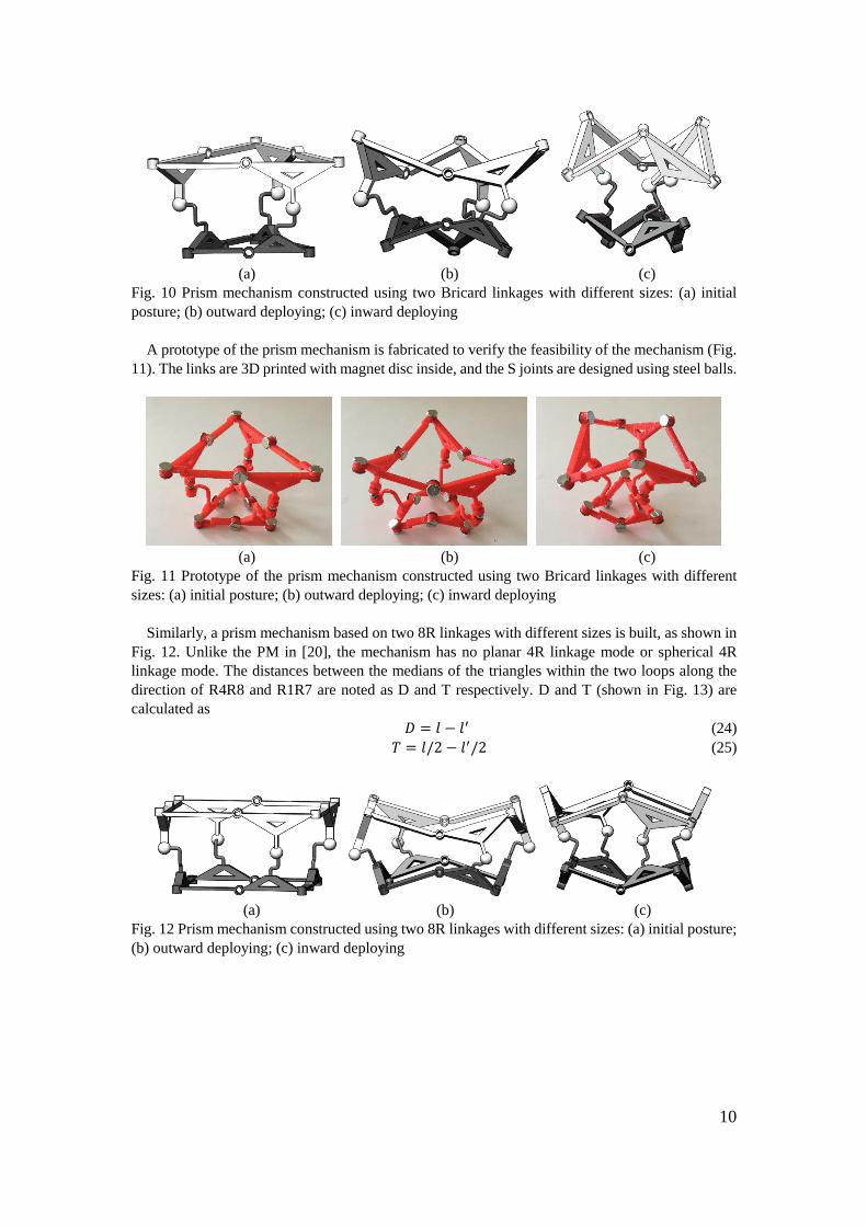
′ |2 = 0.0044𝑚2 in the initial position, when 𝜃 = 120°. Based on the results, a prism mechanism is constructed using the two Bricard linkages with
different sizes, as shown in Fig. 10. The mechanism can be deployed outward [Fig. 10(b)] and
inward [Fig. 10(c)].
10
(a) (b) (c)
Fig. 10 Prism mechanism constructed using two Bricard linkages with different sizes: (a) initial
posture; (b) outward deploying; (c) inward deploying
A prototype of the prism mechanism is fabricated to verify the feasibility of the mechanism (Fig.
11). The links are 3D printed with magnet disc inside, and the S joints are designed using steel balls.
(a) (b) (c)
Fig. 11 Prototype of the prism mechanism constructed using two Bricard linkages with different
sizes: (a) initial posture; (b) outward deploying; (c) inward deploying
Similarly, a prism mechanism based on two 8R linkages with different sizes is built, as shown in
Fig. 12. Unlike the PM in [20], the mechanism has no planar 4R linkage mode or spherical 4R
linkage mode. The distances between the medians of the triangles within the two loops along the
direction of R4R8 and R1R7 are noted as D and T respectively. D and T (shown in Fig. 13) are
calculated as
𝐷 = 𝑙 − 𝑙′ (24)
𝑇 = 𝑙/2 − 𝑙′/2 (25)
(a) (b) (c)
Fig. 12 Prism mechanism constructed using two 8R linkages with different sizes: (a) initial posture;
(b) outward deploying; (c) inward deploying
11
T
D
R1 R2 R3
R4
R5R6R7
R8
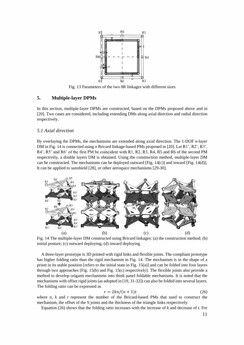
Fig. 13 Parameters of the two 8R linkages with different sizes
5. Multiple-layer DPMs
In this section, multiple-layer DPMs are constructed, based on the DPMs proposed above and in
[20]. Two cases are considered, including extending DMs along axial direction and radial direction
respectively.
5.1 Axial direction
By overlaying the DPMs, the mechanisms are extended along axial direction. The 1-DOF n-layer
DM in Fig. 14 is connected using n Bricard linkage-based PMs proposed in [20]. Let R1’, R2’, R3’,
R4’, R5’ and R6’ of the first PM be coincident with R1, R2, R3, R4, R5 and R6 of the second PM
respectively, a double layers DM is obtained. Using the construction method, multiple-layer DM
can be constructed. The mechanisms can be deployed outward [Fig. 14(c)] and inward [Fig. 14(d)].
It can be applied to sunshield [28], or other aerospace mechanisms [29-30].
(a) (b) (c) (d)
Fig. 14 The multiple-layer DM constructed using Bricard linkages: (a) the construction method; (b)
initial posture; (c) outward deploying; (d) inward deploying
A three-layer prototype is 3D printed with rigid links and flexible joints. The compliant prototype
has higher folding ratio than the rigid mechanism in Fig. 14. The mechanism is in the shape of a
prism in its stable position [refers to the initial state in Fig. 15(a)] and can be folded into four layers
through two approaches [Fig. 15(b) and Fig. 15(c) respectively]. The flexible joints also provide a
method to develop origami mechanisms into think panel foldable mechanisms. It is noted that the
mechanisms with offset rigid joints (as adopted in [19, 31-32]) can also be folded into several layers.
The folding ratio can be expressed as
𝑟 = 2𝑘𝑛/(𝑛 + 1)𝑡 (26)
where n, k and t represent the number of the Bricard-based PMs that used to construct the
mechanism, the offset of the S joints and the thickness of the triangle links respectively.
Equation (26) shows that the folding ratio increases with the increase of k and decrease of t. For
12
the prototype shown in Fig. 15, we have n = 3, k = 0.02m, t = 0.005m, and its folding ratio is 6.
(a) (b) (c)
Fig. 15 The prototype of the multiple-layer DM constructed using Bricard linkages: (a) initial
posture; (b) outward deploying; (c) inward deploying
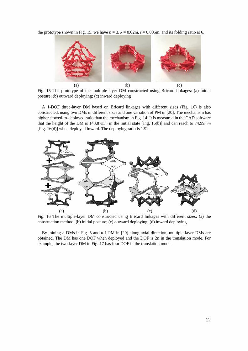
A 1-DOF three-layer DM based on Bricard linkages with different sizes (Fig. 16) is also
constructed, using two DMs in different sizes and one variation of PM in [20]. The mechanism has
higher stowed-to-deployed ratio than the mechanism in Fig. 14. It is measured in the CAD software
that the height of the DM is 143.87mm in the initial state [Fig. 16(b)] and can reach to 74.99mm
[Fig. 16(d)] when deployed inward. The deploying ratio is 1.92.
(a) (b) (c) (d)
Fig. 16 The multiple-layer DM constructed using Bricard linkages with different sizes: (a) the
construction method; (b) initial posture; (c) outward deploying; (d) inward deploying
By joining n DMs in Fig. 5 and n-1 PM in [20] along axial direction, multiple-layer DMs are
obtained. The DM has one DOF when deployed and the DOF is 2n in the translation mode. For
example, the two-layer DM in Fig. 17 has four DOF in the translation mode.
13
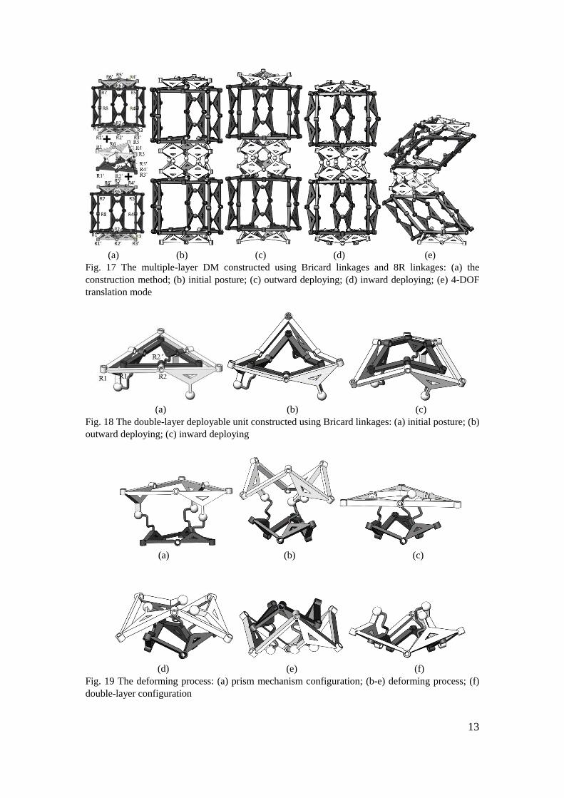
(a) (b) (c) (d) (e)
Fig. 17 The multiple-layer DM constructed using Bricard linkages and 8R linkages: (a) the
construction method; (b) initial posture; (c) outward deploying; (d) inward deploying; (e) 4-DOF
translation mode
(a) (b) (c)
Fig. 18 The double-layer deployable unit constructed using Bricard linkages: (a) initial posture; (b)
outward deploying; (c) inward deploying
(a) (b) (c)
(d) (e) (f)
Fig. 19 The deforming process: (a) prism mechanism configuration; (b-e) deforming process; (f)
double-layer configuration
14
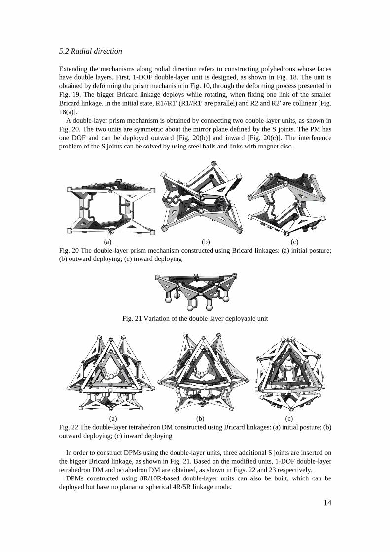
5.2 Radial direction
Extending the mechanisms along radial direction refers to constructing polyhedrons whose faces
have double layers. First, 1-DOF double-layer unit is designed, as shown in Fig. 18. The unit is
obtained by deforming the prism mechanism in Fig. 10, through the deforming process presented in
Fig. 19. The bigger Bricard linkage deploys while rotating, when fixing one link of the smaller
Bricard linkage. In the initial state, R1//R1’ (R1//R1’ are parallel) and R2 and R2’ are collinear [Fig.
18(a)].
A double-layer prism mechanism is obtained by connecting two double-layer units, as shown in
Fig. 20. The two units are symmetric about the mirror plane defined by the S joints. The PM has
one DOF and can be deployed outward [Fig. 20(b)] and inward [Fig. 20(c)]. The interference
problem of the S joints can be solved by using steel balls and links with magnet disc.
(a) (b) (c)
Fig. 20 The double-layer prism mechanism constructed using Bricard linkages: (a) initial posture;
(b) outward deploying; (c) inward deploying
Fig. 21 Variation of the double-layer deployable unit
(a) (b) (c)
Fig. 22 The double-layer tetrahedron DM constructed using Bricard linkages: (a) initial posture; (b)
outward deploying; (c) inward deploying
In order to construct DPMs using the double-layer units, three additional S joints are inserted on
the bigger Bricard linkage, as shown in Fig. 21. Based on the modified units, 1-DOF double-layer
tetrahedron DM and octahedron DM are obtained, as shown in Figs. 22 and 23 respectively.
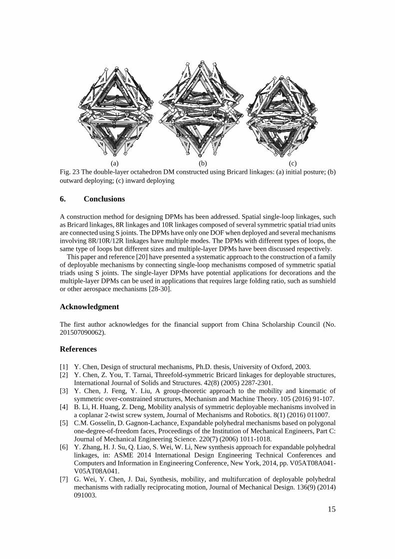
DPMs constructed using 8R/10R-based double-layer units can also be built, which can be
deployed but have no planar or spherical 4R/5R linkage mode.
15
(a) (b) (c)
Fig. 23 The double-layer octahedron DM constructed using Bricard linkages: (a) initial posture; (b)
outward deploying; (c) inward deploying
6. Conclusions
A construction method for designing DPMs has been addressed. Spatial single-loop linkages, such
as Bricard linkages, 8R linkages and 10R linkages composed of several symmetric spatial triad units
are connected using S joints. The DPMs have only one DOF when deployed and several mechanisms
involving 8R/10R/12R linkages have multiple modes. The DPMs with different types of loops, the
same type of loops but different sizes and multiple-layer DPMs have been discussed respectively.
This paper and reference [20] have presented a systematic approach to the construction of a family
of deployable mechanisms by connecting single-loop mechanisms composed of symmetric spatial
triads using S joints. The single-layer DPMs have potential applications for decorations and the
multiple-layer DPMs can be used in applications that requires large folding ratio, such as sunshield
or other aerospace mechanisms [28-30].
Acknowledgment
The first author acknowledges for the financial support from China Scholarship Council (No.
201507090062).
References
[1] Y. Chen, Design of structural mechanisms, Ph.D. thesis, University of Oxford, 2003.
[2] Y. Chen, Z. You, T. Tarnai, Threefold-symmetric Bricard linkages for deployable structures,
International Journal of Solids and Structures. 42(8) (2005) 2287-2301.
[3] Y. Chen, J. Feng, Y. Liu, A group-theoretic approach to the mobility and kinematic of
symmetric over-constrained structures, Mechanism and Machine Theory. 105 (2016) 91-107.
[4] B. Li, H. Huang, Z. Deng, Mobility analysis of symmetric deployable mechanisms involved in
a coplanar 2-twist screw system, Journal of Mechanisms and Robotics. 8(1) (2016) 011007.
[5] C.M. Gosselin, D. Gagnon-Lachance, Expandable polyhedral mechanisms based on polygonal
one-degree-of-freedom faces, Proceedings of the Institution of Mechanical Engineers, Part C:
Journal of Mechanical Engineering Science. 220(7) (2006) 1011-1018.
[6] Y. Zhang, H. J. Su, Q. Liao, S. Wei, W. Li, New synthesis approach for expandable polyhedral
linkages, in: ASME 2014 International Design Engineering Technical Conferences and
Computers and Information in Engineering Conference, New York, 2014, pp. V05AT08A041-
V05AT08A041.
[7] G. Wei, Y. Chen, J. Dai, Synthesis, mobility, and multifurcation of deployable polyhedral
mechanisms with radially reciprocating motion, Journal of Mechanical Design. 136(9) (2014)
091003.
16
[8] G. Kiper, E. Söylemez, A.Ö. Kişisel, A family of deployable polygons and polyhedral,
Mechanism and Machine Theory. 43(5) (2008) 627-640.
[9] K. Wohlhart, Double-ring polyhedral linkages, in: Interdisciplinary Applications of
Kinematics, 2012, pp. 1-17.
[10] H. Guo, C. Shi, Y. Tang, R. Liu, Z. Deng, Design and study for dynamics characteristics of
double-layer loop deployable antenna mechanism, in: ASME 2016 International Design
Engineering Technical Conferences and Computers and Information in Engineering
Conference, Charlotte, 2016, pp. V05BT07A052-V05BT07A052.
[11] Y. Chen, L. Fan, J. Feng, Kinematic of symmetric deployable scissor-hinge structures with
integral mechanism mode, Computers & Structures, 191 (2017) 140-152.
[12] Y. Chen, J. Feng, Improved symmetry method for the mobility of regular structures using graph
products, Journal of Structural Engineering. 142(9) (2016) 04016051.
[13] G. Kiper, F. Gürcü, K. Korkmaz, E. Söylemez, Kinematic design of a reconfigurable
deployable canopy, in: New Trends in Mechanism and Machine Science, 2015, pp. 167-174.
[14] R. Li, Y. Yao, X. Kong, A class of reconfigurable deployable platonic mechanisms,
Mechanism and Machine Theory. 105 (2016) 409-427.
[15] G. Wei, J. Dai, Reconfigurable and deployable platonic mechanisms with a variable revolute
joint, in: Advances in Robot Kinematics, 2014, pp. 485-495.
[16] J. Wang, Y. Yao, X. Kong, A rolling mechanism with two modes of planar and spherical
linkages, Proceedings of the Institution of Mechanical Engineers, Part C: Journal of
Mechanical Engineering Science. 230(12) (2016) 2110-2123.
[17] X. Kong, Y. Jin, Type synthesis of 3-DOF multi-mode translational/spherical parallel
manipulators with lockable joints, Mechanism and Machine Theory. 96 (2016) 323-333.
[18] J. S. Zhao, Z. F. Yan, F. L. Chu, A reconfigurable linkage and its applications in lift
mechanism, in: Advances in Reconfigurable Mechanisms and Robots I, London, 2012, pp.
815-829.
[19] J. Wang, G. Bai, X. Kong, Single-loop foldable 8R mechanisms with multiple modes, in: New
Trends in Mechanism and Machine Science, Springer International Publishing, Nantes, 2016,
pp. 503-510.
[20] J. Wang, X. Kong, Deployable mechanisms constructed by connecting orthogonal Bricard or
extension using S joint, Mechanism and Machine Theory. 120 (2018) 178-191.
[21] X. Kong, X. He, D. Li, A 6R single-loop overconstrained spatial mechanism that has two pairs
of revolute joints with intersecting axes and one pair of revolute joints with parallel axes, in:
Proceedings of the ASME 2017 International Design Engineering Technical Conferences &
Computers and Information in Engineering Conference, Cleveland, 2017, DETC2017-67419.
[22] Y. Tian, Y. Yao, J. Wang, A rolling 8-bar linkage mechanism, Journal of Mechanisms and
Robotics. 7(4) (2015) 041002.
[23] J. Denavit, R.S. Hartenberg, A kinematic notation for lower-pair mechanisms based on
matrices, Transactions of the ASME, Journal of Applied Mechanics. 22 (2) (1955) 215–221.
[24] K. H. Hunt, Kinematic geometry of mechanisms, Oxford University Press, Oxford (1978).
[25] G. Gogu, Mobility of mechanisms: a critical review, Mechanism and Machine Theory. 40(9)
(2005) 1068-1097.
[26] D. St-Onge, C. Gosselin, Synthesis and design of a one degree-of-freedom planar deployable
mechanism with a large expansion ratio, Journal of Mechanisms and Robotics. 8(2) (2016)
021025.
[27] T. Laliberté, C. M. Gosselin, Polyhedra with articulated faces, in: Proceedings of the 12th
IFToMM World Congress, Besançon, 2007, pp. 18-21.
[28] L. Wilson, S. Pellegrino, R. Danner, Origami sunshield concepts for space telescopes, AIAA
Paper. 2013-1594 (2013).
[29] J. Morgan, S. P. Magleby, L. L. Howell, An approach to designing origami-adapted aerospace
mechanisms, Journal of Mechanical Design. 138(5) (2016) 052301.
[30] S. D. Guest, Deployable structures: concepts and analysis, University of Cambridge, 1994.
[31] Y. Chen, R. Peng, Z. You, Origami of thick panels, Science. 349(6246) (2015) 396-400.
[32] B. J. Edmondson, R. J. Lang, S. P. Magleby, L. L. Howell, An offset panel technique for thick
rigidly foldable origami, in: ASME 2014 International Design Engineering Technical

17
Conferences and Computers and Information in Engineering Conference, New York, 2014,
DETC2014-35606.