
Department of Transportation - U.S. Government … · Department of Transportation ... rebuild...
45
Vol. 77 Thursday, No. 120 June 21, 2012 Part II Department of Transportation National Highway Traffic Safety Administration 49 CFR Part 571 Federal Motor Vehicle Safety Standards; Glazing Materials; Proposed Rule VerDate Mar<15>2010 18:50 Jun 20, 2012 Jkt 226001 PO 00000 Frm 00001 Fmt 4717 Sfmt 4717 E:\FR\FM\21JNP2.SGM 21JNP2 TKELLEY on DSK3SPTVN1PROD with PROPOSALS2
Transcript of Department of Transportation - U.S. Government … · Department of Transportation ... rebuild...

Vol. 77 Thursday,
No. 120 June 21, 2012
Part II
Department of Transportation National Highway Traffic Safety Administration 49 CFR Part 571 Federal Motor Vehicle Safety Standards; Glazing Materials; Proposed Rule
VerDate Mar<15>2010 18:50 Jun 20, 2012 Jkt 226001 PO 00000 Frm 00001 Fmt 4717 Sfmt 4717 E:\FR\FM\21JNP2.SGM 21JNP2TK
ELL
EY
on
DS
K3S
PT
VN
1PR
OD
with
PR
OP
OS
ALS
2

37478 Federal Register / Vol. 77, No. 120 / Thursday, June 21, 2012 / Proposed Rules
1 The Economic Commission for Europe was established by the United Nations in 1947 to help rebuild post-war Europe, develop economic activity and strengthen economic relations between European countries and between European countries and the other countries of the world.
2 The 1998 Agreement was concluded under the auspices of the United Nations and provides for the establishment of globally harmonized vehicle regulations. This Agreement, whose conclusion was spearheaded by the United States, entered into force
DEPARTMENT OF TRANSPORTATION
National Highway Traffic Safety Administration
49 CFR Part 571
[Docket No. NHTSA–2012–0083]
RIN 2127–AL03
Federal Motor Vehicle Safety Standards; Glazing Materials
AGENCY: National Highway Traffic Safety Administration (NHTSA), Department of Transportation (DOT). ACTION: Notice of proposed rulemaking (NPRM).
SUMMARY: NHTSA is issuing this NPRM as part of the agency’s ongoing effort to harmonize vehicle safety standards under the Economic Commission for Europe 1998 Agreement. Following a vote in favor of establishing a global technical regulation (GTR) on automotive glazing, we are initiating the process for considering adoption of the GTR. The changes proposed in this NPRM to the Federal motor vehicle safety standard on glazing materials would better harmonize U.S. regulatory requirements with those of other industrialized countries, by modernizing the test procedures for tempered glass, laminated glass, and glass-plastic glazing used in front and rear windshields and side windows.
We believe that most of the changes in this proposal would constitute minor amendments that would harmonize differing measurements and performance requirements for similar test procedures. Many of the tests in the GTR are substantially similar to tests currently included in Federal Motor Vehicle Safety Standard No. 205. We believe that the most significant improvements proposed in the GTR include an upgraded fragmentation test designed to better test the tempering of curved tempered glass, and a new procedure for testing an optical property of the windshield at the angle of installation, to better reflect real world driving conditions than the current procedure used in Standard No. 205. Comments are requested on whether these and the other provisions of the GTR are suited for adoption into the Federal glazing standard. DATES: Comments to this proposal must be received on or before August 20, 2012.
ADDRESSES: You may submit comments, identified by the docket number in the heading of this document, by any of the following methods:
• Federal eRulemaking Portal: Go to http://www.regulations.gov. Follow the instructions for submitting comments on the electronic docket site by clicking on ‘‘Help’’ or ‘‘FAQ.’’
• Mail: Docket Management Facility, M–30, U.S. Department of Transportation, 1200 New Jersey Avenue SE., West Building, Ground Floor, Room W12–140, Washington, DC 20590.
• Hand Delivery: U.S. Department of Transportation, 1200 New Jersey Avenue SE., West Building, Ground Floor, Room W12–140, between 9 a.m. and 5 p.m. Eastern Time, Monday through Friday, except Federal holidays.
• Fax: 202–493–2251. Regardless of how you submit
comments, you should mention the docket number of this document.
You may call the Docket Management Facility at 202–366–9826.
Instructions: For detailed instructions on submitting comments and additional information on the rulemaking process, see the Public Participation heading of the SUPPLEMENTARY INFORMATION section of this document. Note that all comments received will be posted without change to http:// www.regulations.gov, including any personal information provided.
Privacy Act: Anyone is able to search the electronic form of all comments received into any of our dockets by the name of the individual submitting the comment (or signing the comment, if submitted on behalf of an association, business, labor union, etc.). You may review DOT’s complete Privacy Act Statement in the Federal Register published on April 11, 2000 (65 FR 19477–78) or you may visit http:// www.dot.gov/privacy.html.
Docket: For access to the docket to read background documents or comments received, go to http:// www.regulations.gov, or the street address listed above. Follow the online instructions for accessing the dockets. FOR FURTHER INFORMATION CONTACT:
For technical issues: Ms. Gayle Dalrymple, Office of Rulemaking, National Highway Traffic Safety Administration, 1200 New Jersey Avenue SE., Washington, DC 20590. Email: [email protected]. Telephone: (202) 366–5559. For legal issues: Mr. Thomas Healy, Office of the Chief Counsel, Vehicle Safety Standards & Harmonization Division, National Highway Traffic Safety Administration, 1200 New Jersey Avenue SE., Washington, DC 20590. Email: [email protected]. Telephone: (202) 366–7161. SUPPLEMENTARY INFORMATION:
Table of Contents
I. Executive Summary II. Background
1. 1998 Agreement 2. Public Participation in Development of
a GTR 3. Objective of Safety Glazing GTR 4. Public Participation in Development of
Glazing GTR III. Overview of Pertinent FMVSS No. 205
Provisions IV. Proposed Changes to FMVSS No. 205
1. Radiation (Light Stability) Test 2. Luminous Transmittance Level 3. Humidity and High Temperature
Resistance Tests 4. Half Pound Ball Drop—Tempered Glass 5. Fracture Test 6. Shot Bag and Dart Drop Tests 7. Half Pound Ball Drop Test—Laminated
Glass 8. Weathering Test 9. Abrasion Resistance 10. Visual Distortion 11. Chemical Resistance, Flammability and
Change in Temperature Tests 12. Penetration Resistance 13. Optional Strength Test
V. Differences Between GTR and Agency Proposal
VI. Proposed Compliance Date VII. Regulatory Notices and Analyses VIII. Public Participation
I. Executive Summary
Performance requirements for glazing materials used in motor vehicles in the U.S. are currently governed by Federal Motor Vehicle Safety Standard (FMVSS) No. 205, Glazing Materials (49 CFR 571.205). FMVSS No. 205 applies to windshields, windows, and interior partitions for use in motor vehicles. FMVSS No. 205 was established in the late 1960s to ensure safe driver visibility and to reduce the likelihood of occupant ejection and injury as a result of contact with glazing materials.
The revisions to FMVSS No. 205 proposed today are part of the agency’s ongoing efforts to seek to harmonize vehicle safety standards under the United Nations/Economic Commission for Europe (UN/ECE) 1 Agreement Concerning the Establishing of Global Technical Regulations for Wheeled Vehicles, Equipment and Parts Which Can Be Fitted And/or Be Used on Wheeled Vehicles (the ‘‘1998 Agreement’’), to which the U.S. is a Contracting Party.2 In 2008, the U.S.
VerDate Mar<15>2010 18:50 Jun 20, 2012 Jkt 226001 PO 00000 Frm 00002 Fmt 4701 Sfmt 4702 E:\FR\FM\21JNP2.SGM 21JNP2TK
ELL
EY
on
DS
K3S
PT
VN
1PR
OD
with
PR
OP
OS
ALS
2
37479 Federal Register / Vol. 77, No. 120 / Thursday, June 21, 2012 / Proposed Rules
in 2000 and is administered by the UN Economic Commission for Europe’s World Forum for the Harmonization of Vehicle Regulations (WP.29).
3 The Secretary of Transportation has delegated the authority to issue safety standards to NHTSA. 49 CFR 1.50.
4 The 10 kg headform test is an optional requirement in the GTR. Each Contracting Party to the 1998 Agreement can decide whether to apply this provision to national/regional law.
5 Nongovernmental organizations may also participate in a consultative capacity in WP.29 and its subsidiary bodies.
voted in favor of establishing the glazing GTR. Background information on the 1998 Agreement and on the development of this GTR is discussed in the next section of this preamble.
As an FMVSS, this proposal is subject to the requirements of the National Highway and Motor Vehicle Safety Act which states that NHTSA ‘‘shall prescribe motor vehicle safety standards.’’ 3 49 U.S.C. 30111. Standards issued under the National Highway and Motor Vehicle Safety Act ‘‘shall be practicable, meet the need for motor vehicle safety, and be stated in objective terms.’’ Id.
NHTSA’s policies in implementing the 1998 Agreement are published in 49 CFR part 553, Appendix C, ‘‘Statement of Policy: Implementation of the United Nations/Economic Commission for Europe (UN/ECE) 1998 Agreement on Global Technical Regulations—Agency Policy Goals and Public Participation.’’ NHTSA’s paramount policy goal under the 1998 Agreement is to ‘‘[c]ontinuously improve safety and seek high levels of safety, particularly by developing and adopting new global technical regulations reflecting consideration of current and anticipated technology and safety problems.’’ Id.
We believe that the changes proposed today to FMVSS No. 205 would modernize the standard’s test procedures for tempered glass, laminated glass, and glass-plastic glazing used in front and rear windshields and side windows, to better reflect real world conditions and eliminate redundant and unnecessary testing. Most of the changes in this proposal amount to minor amendments that would harmonize differing measurements and performance requirements for similar test procedures. Many of the tests in the GTR are substantially similar to tests currently included in FMVSS No. 205.
The GTR has four sets of tests and requirements for mechanical properties: a fragmentation test, a 227 gram (g) steel ball impact test, a 2.26 kilogram (kg) steel ball impact test, and a 10 kg headform impact test.4 Each of the first three of these tests was adopted from widely used procedures currently in effect, with small differences, in all three national regulations examined for
this GTR (European, Japanese, and U.S. safety regulations). Three types of optical qualities are addressed in the GTR: light transmission; optical distortion; and double imaging. The main differences between the European, Japanese, and U.S. standards and regulations examined were not the performance requirements but the test procedures. The GTR resolves those differences. The GTR also includes environmental resistance requirements related to temperature change, fire, chemical resistance, abrasion, radiation, high temperature and humidity. The first four of these were common to all the examined regulations. The remaining three requirements had minor differences, which the GTR resolves.
We believe that the most significant improvements proposed in the GTR include an upgraded fragmentation test designed to better test the tempering of curved tempered glass, and a new procedure for testing an optical property of the windshield at the angle of installation, to better reflect real world driving conditions than the procedure now used in FMVSS No. 205. We are not currently proposing to adopt the headform test because we do not believe that the headform test would provide any additional safety benefits beyond the other penetration resistance test included in the GTR.
Although most of the proposed changes are minor, we anticipate many positive effects from the GTR. As a general matter, vehicle manufacturers, and ultimately, consumers, both here and abroad, can expect to achieve cost savings through the formal harmonization of differing sets of standards when the Contracting Parties to the 1998 Agreement implement the new GTR. Formal harmonization also improves safety by assisting us in adopting best safety practices from around the world and identifying and reducing unwarranted regulatory requirements. The harmonization process also allows manufacturers to focus their compliance and safety resources on glazing regulations whose differences government experts have worked to converge as narrowly as possible. Compliance with a single standard will enhance design flexibility and allow manufacturers to design vehicles that better meet safety standards, resulting in safer vehicles. Further, we support the harmonization process because it allows the agency to leverage scarce resources by consulting with other governing bodies and international experts to share data and knowledge in developing modernized testing and performance standards that enhance safety.
We are unable to quantify the exact impacts of this proposal because we do not know how many glazing manufacturers are currently testing to multiple national glazing standards. Those currently test to multiple standards will experience a net decrease in testing costs. We estimate that those glazing manufacturers that currently only test to the requirements in FMVSS No. 205 will experience an increase in testing costs of $1,900 to $2,100. We do not believe that the economic impacts of this proposal would be greater than $0.009 to $0.01 per vehicle for a new make and model based on the possible increase in testing costs of $1,900 to $2,100 divided by an average vehicle design lifetime sales of 210,000.
II. Background
1. 1998 Agreement On June 25, 1998, the U.S. became the
first signatory to the 1998 Agreement. This agreement was negotiated under the auspices of the UN/ECE under the leadership of the U.S., the European Community (EC) and Japan. The 1998 Agreement provides for the establishment of GTRs regarding the safety, emissions, energy conservation and theft prevention of wheeled vehicles, equipment and parts. The 1998 Agreement entered into force on August 25, 2000.
By establishing GTRs under the 1998 Agreement, the Contracting Parties seek to develop harmonization in motor vehicle regulations at the regional and national levels.5 Under the 1998 Agreement, countries voting ‘‘yes’’ on a GTR agree to begin their processes for adopting the provisions of the GTR, e.g., in the U.S., to issue an NPRM or advance NPRM. However, as to whether the GTR should ultimately be adopted, the Agreement recognizes that governments should have that authority to determine whether the GTR meets their safety needs.
The UN/ECE World Forum for Harmonization of Vehicle Regulations (WP.29) administers the 1998 Agreement. Four committees coordinate the activities of WP.29: AC.2 manages the coordination of work of WP.29, while AC.3 is the ‘‘Executive Committee’’ for the 1998 Agreement. There are also 6 permanent subsidiary bodies of WP.29, known as GRs (Groups of Rapporteurs) that assist WP.29 in researching, analyzing and developing technical regulations. One of the GRs is the ‘‘Working Party on General Safety Provisions’’ (GRSG), to which WP.29
VerDate Mar<15>2010 18:50 Jun 20, 2012 Jkt 226001 PO 00000 Frm 00003 Fmt 4701 Sfmt 4702 E:\FR\FM\21JNP2.SGM 21JNP2TK
ELL
EY
on
DS
K3S
PT
VN
1PR
OD
with
PR
OP
OS
ALS
2

37480 Federal Register / Vol. 77, No. 120 / Thursday, June 21, 2012 / Proposed Rules
6 49 CFR part 553, App. C (describing the agency’s procedures for ensuring public participation in the GTR process).
7 Id. 8 The GTR process leaves it up to NHTSA to
decide the appropriate next step in the rulemaking process, after receiving and considering the comments we received. NHTSA may issue a final rule adopting the regulation, a supplemental NPRM, or a notice terminating the rulemaking action. 49 CFR Part 553, App. C.
9 5 U.S.C. 553. 10 49 U.S.C. 30111 et seq.
11 The European Commission later submitted a proposal concerning markings for GTRs in general, at the one-hundred-and-fortieth session of WP.29 in November 2006. As this proposal would be discussed at later sessions of WP.29, only markings concerning the type of material are included in this GTR.
12 49 CFR part 553, App. C. 13 73 FR 7803.
referred the glazing GTR for the preparation of technical recommendations.
2. Public Participation in Development of a GTR
NHTSA has established policies for ensuring public participation at all stages of the GTR process.6
Before submitting a draft proposal for a GTR to WP.29, NHTSA will publish a notice soliciting comment on the draft. If there is a proposal from a Contracting Party other than the U.S., after the proposal has been referred to a GR and has been made available in English by WP.29, NHTSA will make the draft proposal available in the DOT docket and will publish a notice requesting comment on the draft proposal. The agency will consider the comments in developing the U.S. position on the proposal.
If a GR recommends a draft GTR to the AC.3 concerning potential establishment of the GTR, NHTSA will make the recommended GTR available in the docket after it is made available by WP.29 and will request comment on the document. Before participating in a vote of the Executive Committee regarding the establishment of the GTR, NHTSA will consider the comments and develop a U.S. position on the recommended GTR.
It is important to emphasize that, in the event the U.S. votes ‘‘yes’’ for establishment of a GTR, we will seek and consider public comments on the suitability of the GTR as an FMVSS. Under the GTR process, countries voting ‘‘yes’’ on a GTR have only agreed to begin their processes for rulemaking on the GTR. Under our procedures,7 NHTSA will publish a notice requesting public comment on adopting the regulation as a U.S. standard. Any decision by NHTSA as to whether to issue a final rule on adopting the regulation will be made in accordance with applicable U.S. law, after careful consideration of public comments.8 NHTSA’s decision as to whether to adopt a GTR as a Federal motor vehicle safety standard is governed by the procedures for informal rulemaking of the Administrative Procedure Act, 9 the National Traffic and Motor Vehicle
Safety Act, 10 and NHTSA’s rulemaking regulations (49 CFR Part 553, Rulemaking Procedures).
3. Objective of Safety Glazing GTR
In October 2002, WP.29 adopted the 1998 Global Agreement Programme of Work (agreed upon subjects for which GTRs should be developed), which included safety glazing, and created an informal working group to draft the glazing GTR under the Chairmanship of Germany. The working group consisted of automotive glazing experts from governmental administrations, technical services, glass industry and automotive organizations from different countries worldwide.
The objective of the group was to develop an internationally harmonized standard regarding the safety of glass automotive glazing materials. The group developed the GTR based on the requirements in UN/ECE Regulation No. 43, American National Standards Institute (ANSI) Standard Z26.1, and the Japanese Industrial Standard. The scope of the glazing GTR was restricted to glass safety glazing; other materials, such as plastics, were excluded from this GTR’s consideration.
The GTR includes requirements and tests to ensure that the mechanical properties, optical qualities and environmental resistance of glazing are satisfactory. It does not include type approval, plastic glazing, bullet resistance glazing and installation requirements. These subjects were left to the discretion of the Contracting Parties. The informal group determined not to include installation requirements in the GTR because existing national or regional regulations or legislation covering installation requirements differ significantly. For instance, the requirements for light transmission levels in glazing installed in rearward vision areas vary widely. The informal working group suggested, and AC.3 agreed, that adding an installation requirement into the GTR should be postponed, as it would lengthen the development time for the GTR.
Marking requirements were also not included in the GTR. Existing national or regional regulations specify marking requirements that usually relate to 3 categories: (1) The type of material, (2) identification of the manufacturer, and/ or (3) the regulations/legislation the glazing meets. Responding to suggestions from the informal group, AC.3 agreed that the GTR would only consider the possibility to include
markings for the ‘‘type of material’’ in the GTR.11
4. Public Participation in Development of Glazing GTR
In October 2004, in accordance with the agency’s procedures for considering GTRs,12 NHTSA docketed the draft GTR addressing glazing proposed by Germany (Docket No. NHTSA–2003– 14395) and published a notice in the Federal Register soliciting comment on the draft (69 FR 60460, 60462; October 8, 2004). NHTSA received no comments on the document.
On October 10, 2006, NHTSA published another notice describing the agency’s work on GTR activities, including the glazing draft GTR (Docket No. NHTSA–2003–14395). In July 2007, NHTSA received comments on the draft GTR from the Society of Automotive Engineers (SAE) Glazing Committee. The SAE Glazing Committee’s comment included requests for clarification of technical rationale and justification, adding definitions of key terms and clarification of testing and performance requirements. The agency made recommendations to the informal working group to implement some of the SAE comments into the GTR.
On February 11, 2008, NHTSA published a notice in the Federal Register informing the public that the WP.29 intended to vote on the GTR covering glazing at the March 2008 session, and soliciting comment on how the agency should vote on the proposal.13
The agency received six comments in response to the request for comment, from: the Alliance of Automobile Manufactures (Alliance), Volkswagen Group of America (VW), Solutia, PPG Industries (PPG), Mr. John Turnbull (former Chairman of the SAE Glazing Standards Committee), and Automotive Components Holdings (Automotive Components).
The Alliance and VW recommended that the U.S. vote in favor of the GTR at the March 2008 session, while expressing the view that WP.29 needed to initiate a GTR on issues such as marking, plastics, state-of-the-art glazing and installation requirements.
The other commenters did not support the GTR, believing, among other things, that the GTR includes provisions
VerDate Mar<15>2010 18:50 Jun 20, 2012 Jkt 226001 PO 00000 Frm 00004 Fmt 4701 Sfmt 4702 E:\FR\FM\21JNP2.SGM 21JNP2TK
ELL
EY
on
DS
K3S
PT
VN
1PR
OD
with
PR
OP
OS
ALS
2

37481 Federal Register / Vol. 77, No. 120 / Thursday, June 21, 2012 / Proposed Rules
14 ANSI is a custodian for voluntary commercial standards developed by committees such as the Society of Automotive Engineers (SAE). The SAE Glazing Committee (made up of individuals knowledgeable in the field of automotive glazing) periodically revises the existing ANSI glazing standards.
15 Certain items of glazing are also defined according to their construction characteristics. For example, item 1 glazing may be a multiple glazed unit, which is more than one sheet of glazing in a common mounting. Multiple glazed unit item 1 glazing needs to meet a different set of tests than glazing that is not a multiple glazed unit.
16 On July 25, 2003, NHTSA published the current version of FMVSS No. 205 in a final rule incorporating by reference ANSI Z26.1–1996 (68 FR 43964). ANSI Z26.1–1996 is the applicable ANSI standard in FMVSS No. 205, even though the SAE Glazing Committee has published a later version of ANSI Z26.1. Since the Federal motor vehicle safety standards cannot be changed except by following the informal rulemaking procedures of the Administrative Procedure Act, revisions to the ANSI standard do not become part of FMVSS No. 205 unless we conduct a rulemaking that expressly identifies and incorporates them. NHTSA analyzes the revisions of the ANSI standard for improved safety benefits, harmonization, obsolete requirements, and any increased costs associated with compliance, and conducts a rulemaking, as appropriate, to incorporate the new version.
17 It is NHTSA’s position that, for passenger cars, all windows in the passenger compartment are requisite for driving visibility.
that were not supported by data or were unjustified from a safety standpoint, or fails to include tests now included in FMVSS No. 205 that they believe meet a safety need.
The agency considered the comments when deciding how to vote on the proposed GTR. It appeared that some of the objections were speculative or were opposed to any kind of change to the standard, while others raised points that were worthy of further discussion. After analyzing the comments, we did not believe that the commenters raised insurmountable opposition to the opportunity to modernize the glazing standard, but we did consider several of the opposing comments worthy of follow-up. We determined that the objections to the draft GTR could be aired out and resolved in the notice- and-comment process of NHTSA rulemaking. This NPRM highlights those concerns and, in turn, requests comments on those issues.
All in all, NHTSA believed the proposed GTR to be worthwhile for consideration. The agency believed the GTR presented an opportunity to take steps toward harmonization. The GTR achieves a narrowing of the convergence of disparate national standards that seek to mitigate the same motor vehicle safety problem and presents an opportunity to modernize FMVSS No. 205 in a manner consistent with harmonization. Accordingly, NHTSA voted yes on the GTR in March 2008.
Today’s NPRM initiates rulemaking and requests public comment on adopting the GTR’s provisions.
III. Overview of Pertinent FMVSS No. 205 Provisions
FMVSS No. 205, Glazing materials, specifies performance requirements and test procedures for glazing installed in motor vehicles. The standard specifies performance tests that the glazing must pass and locations in the vehicle where particular types, or ‘‘items,’’ of glazing may be installed. The standard also includes certification and marking requirements for original and replacement glazing materials used in motor vehicles.
FMVSS No. 205 incorporates by reference American National Standards Institute (ANSI) 14 Standard Z26.1, ‘‘American National Standard for Safety Glazing Materials for Glazing Motor Vehicles and Motor Vehicle Equipment
Operating on Land Highways—Safety Standard,’’ ANSI/SAE Z26.1–1996 (hereinafter referred to as ‘‘ANSI Z26.1’’). ANSI Z26.1 describes 20 different ‘‘items’’ of glazing for motor vehicle use.
Each item of glazing is generally defined by its ability to pass a specified set of tests.15 ANSI Z26.1 includes a total of 31 specific test procedures designed to assess various mechanical and optical properties and the environmental resistance of the items of glazing.16 The set of tests that the item of glazing must pass varies from item to item, based in part on the type of vehicle, and location within that vehicle, in which the glazing will be installed. The tests are listed in a chart in ANSI Z26.1, with detailed test procedures also set forth there. The tests seek to ensure adequate safety performance of vehicle glazing for the item’s application.
This NPRM pertains to the following test requirements of ANSI Z26.1, which are incorporated into FMVSS No. 205:
1. A radiation (light stability) test for laminated glass, tempered glass, and glass-plastic (for glazing installed in areas requisite for driving visibility), ensuring that the glazing retains its luminous transmittance after prolonged exposure to sunlight (ANSI Z26.1, paragraph S5.1);
2. A 70 percent luminous transmittance requirement (for glazing installed in areas requisite for driving visibility 17) (ANSI Z26.1, paragraph S5.2);
3. Humidity and high temperature resistance tests (laminated glass and glass-faced plastics) (ANSI Z26.1, paragraphs 5.3, 5.4, 5.5), to determine if
the glazing will withstand environmental effects;
4. A half-pound ball impact test (tempered glass), ensuring that the glass has a certain minimum strength to resist impact from external projectiles, such as small stones (ANSI Z26.1, paragraph S5.6);
5. A fracture test (tempered glass), to minimize the risk of injury caused by fragments of fractured glazing material (ANSI Z26.1, paragraph S5.7);
6. Shot bag and dart drop tests (tempered glass), to ensure glazing material has a certain minimum strength to resist impact of large and small objects (ANSI Z26.1, paragraphs 5.8, 5.9);
7. A half-pound ball drop test (laminated glass), to ensure the glazing resists penetration by heavy objects, such as body parts, that may come into contact with the glazing in the event of a crash (ANSI Z26.1, paragraph S5.12);
8. A weathering test (plastic and glass- plastic glazing), to ensure the plastic face mounted on the exterior of the vehicle will withstand simulated weathering over a long period of time (ANSI Z26.1, paragraph S5.16);
9. An abrasion resistance test (ANSI Z26.1, paragraph S5.17);
10. An optical distortion test (glazing materials used as windshields), ensuring safe driver visibility through the windshield (ANSI Z26.1, paragraph S5.15);
11. Chemical resistance, change in temperature, and flammability tests (ANSI Z26.1, paragraphs 5.19, 5.23, 5.24, 5.28); and,
12. A penetration resistance test (laminated glass), to assess the glazing’s resistance to penetration by heavy objects, such as body parts (ANSI Z26.1, paragraph S5.26).
13. In addition, comments are requested on the GTR’s optional 10 kg (22 lb) headform drop test, which is not currently included in ANSI Z26.1.
IV. Proposed Changes to FMVSS No. 205
The agency solicits comment on the following proposed changes to FMVSS No. 205’s requirements. These proposals implement the GTR provisions.
As noted earlier, we believe that, for the most part, the changes proposed in the GTR do not substantially alter the current requirements of FMVSS No. 205. Many of the changes are minor amendments to bridge small differences in the current regulatory requirements of Contracting Parties. Other changes attempt to update FMVSS No. 205 to better test performance of modern glazing and to delete obsolete requirements. The proposal’s new
VerDate Mar<15>2010 18:50 Jun 20, 2012 Jkt 226001 PO 00000 Frm 00005 Fmt 4701 Sfmt 4702 E:\FR\FM\21JNP2.SGM 21JNP2TK
ELL
EY
on
DS
K3S
PT
VN
1PR
OD
with
PR
OP
OS
ALS
2

37482 Federal Register / Vol. 77, No. 120 / Thursday, June 21, 2012 / Proposed Rules
18 Specifically, the requirements for light transmission levels in glazing installed in rearward vision areas vary widely. The informal working group developing the GTR decided to postpone adding the installation requirement into the GTR as it would lengthen the development time for the GTR.
19 All comments referred to in this section were submitted to Docket NHTSA–2008–0008, responding to NHTSA’s request for comments pending a vote on the draft GTR.
20 Section 4 of ANSI Z26.1, Application of Tests, specifies the areas of vehicles that are required to be equipped with glazing with a 70 percent luminous transmittance level. NHTSA’s position is that for passenger cars, all windows in the passenger compartment are requisite for driving visibility.
marking requirements for tempered glass, laminated glass and glass-plastic glass are substantially similar to the marking requirements of ANSI Z26.1.
The changes in the proposed GTR are only applicable to tempered glass, laminated glass, and glass face plastic glazing. We do not propose changing FMVSS No. 205’s requirements for other glazing. ANSI Z26.1 will continue to apply, unchanged, to bullet resistant glazing and glazing for use on motorcycles, slide-in campers, and pick up covers designed to carry persons while in motion. ANSI Z26.1 will also continue to apply, unchanged, to glazing for use on trucks, buses and MPVs in locations not requisite for driving visibility.
This NPRM does not propose changes to FMVSS No. 205 requirements that specify where items may be installed. As noted above, the GTR does not contain specifications for installation of the glazing. Installation was not included because existing national or regional regulations or legislation covering installation requirements differ significantly.18 This NPRM also does not include proposals for comprehensive marking of glazing. As explained earlier, comprehensive marking requirements were not included in the GTR.
FMVSS No. 205 is currently very brief as set forth in 49 CFR 571.205, since it incorporates by reference ANSI Z26.1. The proposed regulatory text of this NPRM would significantly lengthen 49 CFR 571.205 because the provisions of the GTR would be set forth in the regulatory text of the standard rather than being incorporated, for the most part, in a separate document (i.e., in the ANSI standard). Nonetheless, we emphasize that we believe the proposed changes are relatively minor.
The agency is considering adopting all the changes proposed in the GTR. However, after reviewing the comments to this NPRM and other relevant information, the agency may choose to incorporate some of the proposed tests in the GTR while retaining some of the current requirements of FMVSS No. 205.
The proposed regulatory text is taken almost verbatim from the GTR. Consistent with principles for Plain Language, we are amenable to suggestions as to how we can improve the regulatory text. We have noted
periodically in the text where we wish to highlight a request for suggestions on improving the text.
The agency is proposing to add definitions for over thirty new terms to the definitions section of FMVSS No. 205. These new definitions would define terms used in the GTR which are used in the new regulatory language that would be added to FMVSS No. 205.
1. Radiation (Light Stability) Test Paragraph S5.1 of ANSI Z26.1
specifies a light stability test for laminated glass, tempered glass, and glass-plastic installed in areas of a vehicle requisite for driving visibility. The purpose of the test is to ensure that the glazing retains its luminous transmittance after prolonged exposure to sunlight.
The test specimen is exposed to ultra- violet radiation for 100 hours. After being exposed to radiation, the specimen is tested for luminous transmittance. The performance requirements for the test require that the glazing retain 95 percent of its pre- exposure luminous transmittance.
For laminated glass used in windshields and glass plastic glazing, the light stability test in ANSI Z26.1 contains an extra step. After being exposed to radiation, laminated glass and glass-plastic samples are immersed in boiling water and examined for decomposition.
Proposed Change The process used in the radiation test
in the GTR, located in S6.7 of today’s proposed regulatory text, is similar to the process used in the light stability test in paragraph S5.1 of ANSI Z26.1. The agency believes that the radiation test in the GTR is generally equivalent to the current light stability test in the ANSI standard. The purpose of both tests is to ensure that the glazing retains its luminous transmittance after prolonged exposure to sunlight. Both tests examine the ability of laminated glass to retain its luminous transmittance when exposed to ultraviolet (UV) radiation.
There are differences, however. Consistent with the GTR, we propose that the light stability test of FMVSS No. 205 be amended to not apply to tempered glass. The GTR informal working group suggested that this test is not needed for tempered glass because tempered glass generally does not react to UV radiation. Also, tempered glass by its nature is a stable and durable material and generally would not degrade after prolonged exposure to sunlight. NHTSA has no reason to disagree; however, the agency seeks
comment on this proposal to exclude tempered glass from the resistance to UV radiation test.
Further, consistent with the GTR, we propose that laminated glass and glass plastics would not be exposed to boiling water after exposure to radiation. The GTR informal working group suggested that submerging the samples in boiling water is duplicative of the resistance to high temperature test, see below, and does not need to be included from a safety perspective. NHTSA has no reason to disagree; however, we request comments on this issue.
We note that previously, Mr. Turnbull commented 19 in opposition to the GTR’s provisions on the radiation test. He stated that the method specifies the radiation source (lamp) by general dimensions but is non-specific regarding the actual amount of UV spectral radiation generated. In response, we point out that the GTR specifies that each test piece shall be exposed to the equivalent of 100 hours of ultraviolet radiation at 1,400 W/m2. NHTSA tentatively believes that the terms of this test are specified with sufficient clarity to make the test repeatable.
In previous comments, Solutia expressed concern that, without the thermal resistance testing post irradiation, there is no assurance the glazing will maintain clarity during exposure to sun and heat. Comments are requested on this issue.
2. Luminous Transmittance Level Paragraph S5.2 of ANSI Z26.1
requires glazing materials for use in areas of a vehicle requisite for driving visibility to undergo a test for luminous transmittance.20 The test requires that the glazing have a luminous transmittance of not less than 70 percent. The purpose of this test is to ensure safe driver visibility. The current standard requires the entire windshield except for the shade ban area and the area where the rearview mirror or rain detector is mounted to the windshield to meet the performance requirements of this test.
Proposed Change The GTR specifies the same 70
percent luminous transmittance level as
VerDate Mar<15>2010 18:50 Jun 20, 2012 Jkt 226001 PO 00000 Frm 00006 Fmt 4701 Sfmt 4702 E:\FR\FM\21JNP2.SGM 21JNP2TK
ELL
EY
on
DS
K3S
PT
VN
1PR
OD
with
PR
OP
OS
ALS
2
37483 Federal Register / Vol. 77, No. 120 / Thursday, June 21, 2012 / Proposed Rules
21 49 CFR 571.104. 22 March 31, 2004 letter of interpretation to
Alliance of Automobile Manufacturers, http:// isearch.nhtsa.gov/files/007749drn-3.html.
23 See June 9, 1987 letter of interpretation to manufacturer whose name has been kept confidential, http://isearch.nhtsa.gov/gm/87/nht87- 2.4.html (stating that a heads-up-display located in an area of the windshield through which the driver could only see the hood was in an area not requisite for driving visibility and was thus allowable); see also November 3, 1988 letter of interpretation to Volkswagen of America, http://isearch.nhtsa.gov/ files/3136o.html (allowing a shade ban with less than 70% luminous transmittance along the bottom edge of the windshield).
the current ANSI Z26.1 luminous transmittance test. Paragraph S5.2.1.1.1 of the proposed regulatory text applies the luminous transmittance test to all glazing requite for the driver’s forward field of vision. The GTR defines the driver’s forward field of vision to be the windshield and the driver and passenger side windows.
The GTR leaves the required luminous transmittance level requisite for the driver’s rearward vision to the discretion of the Contracting Parties. We have decided to maintain the current 70 percent luminous transmittance level for glazing requisite for the driver’s rearward field of vision for passenger cars (S5.2.1.1.2 of the proposed regulatory text). Similar to current FMVSS No. 205 requirements, glazing used on trucks, buses and multipurpose passenger vehicles (MPVs) will only be subject to the luminous transmittance test if installed as a windshield, to the immediate right and left of the driver or the rearmost window if used for driving visibility.
FMVSS No. 205 applies a 70 percent luminous level to the entire windshield, except for shade band area and the area where the rearview mirror or rain detector is mounted to the windshield at the top of the windshield. The GTR requirements for the shade band and opaque area where the rearview mirror is mounted, reflected in paragraph S6.15.3.4 of the proposed regulatory text, are similar to those of FMVSS No. 205.
However, the GTR directly allows an opaque area 25 millimeters (mm) (0.98 inch (in)) wide around the edge of the windshield to aid installation. FMVSS No. 205’s text does not directly exclude any area of the windshield from the luminous transmittance test other than shade band area at the top of the windshield and the opaque area where the rear view mirror is mounted.
We do not believe the addition of an opaque area 25 millimeters (mm) (0.98 inch (in)) wide around the edge of the windshield would constitute a significant change to standard. Already, NHTSA has interpreted FMVSS No. 104, Windshield wiping and washing systems,21 to allow an opaque coating around the edge of the windshield used to cover the glue that fixes the windshield in place.22 If there is an opaque coating to cover the glue, it appears reasonable not to require that small coated area to meet light transmittance requirements since the
driver cannot see the roadway through that area.23 We tentatively conclude that the provision in the GTR that allows an opaque area 25 mm (0.98 in) wide around the edge of the windshield would make the standard clearer by specifying the area of the windshield in which an opaque coating is allowed. We seek comment on this proposed change.
3. Humidity and High Temperature Resistance Tests
A humidity test is currently included in paragraph S5.3 of ANSI Z26.1 in order to determine if laminated glass and glass faced plastics will successfully withstand the effects of moisture in the atmosphere over time. The test requires that three test specimens be kept in a closed container over water for two weeks at a temperature between 49 °C and 54 °C (120 °F and 130 °F). In order to pass the test, the samples must not exhibit any separation of materials. Small areas of separation are allowed within 6.35 mm (0.25 in) of the edge of the sample.
The current standard includes both a boil and a bake test to determine whether safety glazing can withstand exposure to high temperatures over extended periods of time. The boil test, contained in paragraph S5.4 of ANSI Z26.1, is applicable to laminated glass and glass plastics. For the boil test, three samples are placed in 66 °C (150 °F) water for three minutes and then placed in boiling water for three hours.
The bake test, contained in paragraph S5.5 of ANSAI Z26.1, applies to multiple glazed units. It requires three samples to be heated to 100 °C (212 °F) in an oven for two hours.
The performance specifications for both tests require that no bubbles or other defects develop within 13 mm (0.5 in) of the outer edge of the sample.
Proposed Change
The humidity test is substantially similar in both ANSI Z26.1, paragraph 5.3, and the GTR. ANSI Z26.1 requires that the specimens be kept in an enclosed container over water and maintained at a temperature range designed to achieve a relative humidity level of 100 percent. The GTR humidity test, reflected in S6.8 of today’s
proposed regulatory text, specifies a 50 °C (122 °F) temperature at which the specimens must be kept and a 95 percent relative humidity level.
The test for resistance to high temperature in the GTR, reflected in S6.6 of the proposed regulatory text, includes the procedures for both the boil and the bake tests currently included in paragraphs 5.4 and 5.5, respectively, of ANSI Z26.1. The resistance to high temperature test in the proposed GTR requires the sample to be heated to 100 °C (212 °F) but does not specify a method for achieving the required temperature. The GTR does, however, provide that laminated glass may be tested by submersing the test piece in boiling water. The agency also solicits comment on whether a measurement tolerance of ±2 °C should be added to paragraph S6.6.1.1.
Also, the procedures for the boil test in the GTR differ slightly from the requirements of paragraph S5.4 of ANSI Z26.1. The boil test in ANSI Z26.1 requires that the sample be immersed in 66 °C (150 °F) water for 3 minutes before being transferred to boiling water to minimize thermal shock while the GTR does not include this step.
For both the humidity and the high temperature resistance tests, because cutting induces stress into the glazing, the GTR allows a 25 mm (0.98 in) area at the edge of a cut piece of glazing within which conformance to the standard will not be assessed. ANSI Z26.1 allows a 6.35 mm (0.25 in) area within which conformance will not be assessed for the humidity test and a 13 mm (0.5 in) area for the high temperature resistance tests. We have no reason to believe that the GTR’s larger area would result in a decrease in safety benefit with its use. However, we seek specific comment on whether the larger area is appropriate.
The agency seeks comment on the appropriateness of the proposed changes to the boil and bake tests of the GTR.
4. Half Pound Ball Drop—Tempered Glass
Paragraph 5.6 of ANSI Z26.1 requires that tempered glass undergo an impact ball test in which a steel ball weighing 227 grams (g) (8 ounces (oz)) is dropped onto the test specimen from a height of 3.1 meters (m) (10 feet (ft)). The purpose of this test is to ensure that the glass has a certain minimum strength to resist impact from external projectiles such as small stones.
Proposed Change The procedure in the GTR for the ball
drop test applicable to tempered glass
VerDate Mar<15>2010 19:32 Jun 20, 2012 Jkt 226001 PO 00000 Frm 00007 Fmt 4701 Sfmt 4702 E:\FR\FM\21JNP2.SGM 21JNP2TK
ELL
EY
on
DS
K3S
PT
VN
1PR
OD
with
PR
OP
OS
ALS
2

37484 Federal Register / Vol. 77, No. 120 / Thursday, June 21, 2012 / Proposed Rules
24 Unpublished one-page analysis, ‘‘Assessment of Toughened Glass Impact Test in Terms of Impact Energy of Flying Object’’; Flat Glass Manufacturers Association of Japan; March 29, 2004.
25 ANSI Z26.1 states (section 5, Test Specifications) that ‘‘[S]ome tests are written so that occasional failure is allowed. Such tests are better adapted to indicate a satisfactory product than less severe tests allowing no failures.’’
26 Laminated glass panes refer to laminated glass installed on locations on the vehicle other than the windshield.
27 Figure 25 of the proposed GTR specifies the second impact point for curved panes. Global technical regulation No. 6, ‘‘Safety Glazing Materials for Motor Vehicles and Motor Vehicle Equipment’’, ECE/TRANS/180/Add.6, 16 May 2008.
28 Id., page 9.
differs from the current requirements in paragraph 5.6 of ANSI Z26.1. The proposed procedure for the ball drop test, which is reflected in paragraph S6.3 of today’s proposed regulatory text, would require that a 227 g (8 ounces (oz)) test ball be dropped onto the exterior face of the glazing mounted on the vehicle from a height of 2 m (6.6 ft). The ball drop test in ANSI Z26.1 uses a steel ball of approximately the same weight dropped from a height of 3.1 m (10 ft).
The drafters of the GTR believe that calculations performed by the Japanese support a finding that a drop height of 2.0 m (6.6 ft) is sufficient for testing the safety performance of tempered glazing. The calculations assumed that the typical piece of debris that came in contact with a vehicle windshield had a mass of 2 to 3 g (0.07 to 0.1 oz). Assuming, in a worst-case scenario, that the 3 g debris impacts a piece of glazing installed on a vehicle at 150 kilometers per hour (km/h) (93 miles per hour (mph)), the study found that the impact energy of the 3 g (0.1 oz) object would be equivalent to the impact energy of a 227 g (8 oz) ball dropped from a height of 1.17 m (3.8 ft).24 We note also that tempered glass is used in side windows, so the impact velocity of small objects on tempered glass could be lower than the impact energy of debris that strikes the vehicle head on in the windshield. For these reasons, we tentatively conclude that the 2 m (6.6 ft) height would be sufficient to assess the toughness of tempered glazing when struck by a stone or other small object.
The GTR also differs from the current ball drop test specified in ANSI Z26.1 by specifying that not less than 8 of the 10 samples tested must not break or fragment. ANSI Z26.1 requires that 10 of the 12 samples must not break or crack.25 The agency tentatively believes that the change in sample size will not significantly impact the test results.
Comments are requested on the proposed changes. We note that, in a previous comment, Mr. Turnbull objected that, ‘‘It is not obvious that any impact studies were actually done with stones or if a 2–3 g stone does represent typical road debris.’’ While no impact studies were performed, the agency believes that the calculations conducted in Japan provide a reasoned basis for
selecting 2 m (6.6 ft) as an appropriate drop high to test the toughness of tempered glass. In establishing the GTR, Contracting Parties are required to reconcile conflicting performance requirements from differing regional and national standards, the agency felt the calculations from Japan adequately ensure the safety of tempered glass when tested from a drop height of 2 m (6.6 ft).
In previous comments, Solutia, PPG and others expressed a concern that the GTR specifies different requirements (e.g., drop height) based on the type of construction of the glazing, rather than on its application, and thus, commenters believed, the GTR ‘‘discriminates against materials.’’ Solutia stated that the GTR requirement for the drop height of the 227 g ball ‘‘specifies that toughened-glass panes [for use in side windows] be tested by dropping the ball from a height of 2 meters whereas, section 6.3.3.3 [of GTR No. 6] requires laminated panes in the same application be tested by dropping the ball from a height of 9 meters. No justification is provided for this difference in ball drop heights.’’
ANSI Z26.1 currently includes different drop heights for laminated and tempered glass used as panes 26 for the 227 g (8 oz) ball drop test based on differing properties of the materials. Tempered glass is designed to withstand rough treatment but it is not resistant to penetration. Laminated glass is not as tough as tempered glass and cracks more easily but is very resistant to penetration. The differing drop heights are designed to test the differing properties of these materials. The performance requirements for the 227 g (8 oz) ball drop test applicable to tempered glass specify that the test piece must not break when the ball is dropped from a height of 2 m (6.53 ft) on to the test piece. The performance requirements for the 227 g (8 oz) ball drop test applicable to laminated glass panes specify that the ball shall not pass through the test piece when the ball is dropped on to the test piece from a height of 9 m (29.53 ft). Thus, the differing drop heights for the 227 g (8 oz) ball drop test applicable to tempered glass and laminated glass panes are included in the GTR to ensure sufficient toughness of tempered glass and sufficient penetration resistance of laminated glass panes. Comments are requested on this issue.
5. Fracture Test
ANSI Z26.1 specifies a fracture test for tempered glass in paragraph S5.7. The purpose of the fracture test is to minimize the risk of injury caused by fragments of fractured glazing material. The test specimen is tested with a spring-loaded center punch or hammer. The specimen is broken at the center of the sample. The fragments of the sample are then weighed. In order to pass the test, no fragment from the fractured specimen is allowed to weigh more than 4.25 g (0.15 oz).
Proposed Changes
ANSI Z26.1 currently specifies a test procedure with only one breaking point in the center of the sample, and a maximum weight for the largest resulting fragment. The GTR fracture test adds a second fragmentation point to verify that the glass has been properly tempered.27 We tentatively agree with this change, because if a glazing piece is significantly curved, testing for fragmentation at only the center of the sample could mask issues with the tempering process. The added fragmentation test point at the point of curvature helps to ensure that the glazing is properly tempered and breaks into a large number of small fragments.
Further, ANSI Z26.1 currently limits the weight of the largest fragment, but not its size. The GTR performance requirements set a minimum number of fragments in a five centimeter square area and limit the length and width of the largest fragment, rather than its weight. The rationale provided in the preamble to the GTR is that newer types of very thin tempered glass could produce a large fragment but have a smaller mass than would be expected with older, thicker glass.28 Accordingly, using weight alone could permit large fragment sizes.
NHTSA agrees that it is possible that thinner tempered glass, when fractured, may produce a fragment that is large in size but relatively small in weight, and that a reasonable alternative is to limit the size of the fragment.
However, the agency seeks comment on the proposed changes. Is the second fragmentation point reasonable? Should fragments be limited by size rather than weight? We note that in a previous comment, PPG expressed the belief that the ANSI test procedure should not be changed. It stated: ‘‘the assumption that
VerDate Mar<15>2010 18:50 Jun 20, 2012 Jkt 226001 PO 00000 Frm 00008 Fmt 4701 Sfmt 4702 E:\FR\FM\21JNP2.SGM 21JNP2TK
ELL
EY
on
DS
K3S
PT
VN
1PR
OD
with
PR
OP
OS
ALS
2

37485 Federal Register / Vol. 77, No. 120 / Thursday, June 21, 2012 / Proposed Rules
thinner [glass] will result in the ability to have larger pieces of glass has not been demonstrated.’’ Automotive Components stated that the GTR procedure is more time consuming and requires glazing manufacturers to break more glass parts, which increases cost. Comments are requested on these issues.
6. Shot Bag and Dart Drop Tests The current standard specifies a shot
bag impact test for tempered glass (ANSI Z26.1, paragraph S5.8). The purpose of the test is to determine whether the glazing material has a certain minimum strength to resist impact of large objects, such as body parts of the vehicle occupant. A 4.99 kg (11 lb) shot bag made of flexible leather is dropped on the specimen from a height of 2.44 m (8 ft) so that it strikes the center of the face of the glazing mounted on the vehicle. Of five test specimens tested, no more than one is allowed to crack or break.
Under FMVSS No. 205, laminated glass is subject to a dart impact test (ANSI Z26.1, paragraph S5.9). The purpose of the test is to ensure the strength of the glazing when impacted by small hard objects. During the test, a 198 g (7 oz) steel dart is dropped from a height of 9.14 m (30 ft) so that it strikes the specimen in the center of the exterior face of the glazing mounted on the vehicle. The performance requirements permit the dart to puncture the specimen, but the dart is not permitted to create a hole in the specimen sufficiently large to allow the dart to pass completely through.
Proposed Change We propose deleting the dart impact
test and the shot bag test from FMVSS No. 205. It appears the tests have become obsolete. The dart impact test and the shot bag test are not included in the GTR. Both tests are not included in the most recent draft version of ANSI Z26.1 being developed by the SAE Glazing Committee.
The dart drop test, currently found in the current version of ANSI Z26.1 reflected in FMVSS No. 205, paragraph S5.9, uses a dart one ounce lighter than the 227g (8 oz) ball dropped from the same height. The agency tentatively concludes that no purpose is served by having both a dart test and a small ball test. It appears that the ball is more representative of the real world hazards encountered by vehicle glazing, and the GTR informal group suggested that the small ball test is slightly more severe. Therefore, the agency tentatively concludes that the GTR, as written without these tests, meets the need for safety.
The purpose of the shot bag test is to assess the strength of the glazing under impact from the interior side by an occupant body part. The drafters of the GTR believed that leather comprising the shot bag could not be specified to a degree of accuracy that would ensure that the results of the test were objective and repeatable. The drafters believed that the variations in the suppleness of the leather played a significant role in the distribution of force in the impact area which affects the glazing’s ability to withstand the force applied by the bag. Further, the GTR committee stated that experience has shown that glazing that passes the shot bag test can sometimes fail the 2.26kg-ball drop test, but the reverse has never been seen. This experience indicates that the shot bag test is not needed to test the resistance of glazing to penetration by large heavy objects. The agency tentatively agrees with the drafters of the GTR that the variations in test conditions caused by the leather on the shot bag can introduce repeatability issues. The agency has also tentatively concluded that the shot bag test duplicates properties of the glazing tested by the 2.226 kg (5 lb) ball drop test included in the GTR.
The agency is soliciting comment on whether the dart drop and the shot bag tests should be removed from FMVSS No. 205.
7. Half Pound Ball Drop Test— Laminated Glass
ANSI Z26.1 specifies an impact ball test in paragraph S5.12 for laminated glass used in windshields. It differs from the impact ball test used on tempered glass. Laminated glass is subjected to an impact ball test in which a 227 g (8 oz) ball is dropped from a height of 9.14 m (30 ft) so that it strikes the specimen in the center of the exterior face of the glazing mounted on the vehicle. The purpose of the test is to determine whether the glazing possesses a certain minimum strength, and to ensure that the glazing is properly constructed. Separation of glass and plastic from the area of the specimen opposite the point of immediate impact of the glass shall not exceed 645 mm2 and total separation of glass from strengthening material shall not exceed 1935 mm2.
Proposed Change The GTR (as reflected in paragraph
S6.3 of today’s proposed regulatory text) changes the drop height for the 227 g (8 oz) ball drop test applicable to laminated glass from 9.14 m (30 ft), as currently specified in ANSI Z26.1 paragraph S5.12, to 9 m (29.5 ft). The
agency does not believe that this change will have any significant impact on the results produced by the test.
However, the GTR differs from ANSI Z26.1 in some respects. The GTR specifies that the 227 g (8 oz) ball drop test is conducted on specimens conditioned at two different temperatures. Ten specimens are tested at a temperature of +40 °C (104 °F) and 10 specimens are tested at ¥20 °C (¥4 °F). At least 8 specimens from each test group must satisfy the proposed performance requirements. ANSI Z26.1 currently requires that 12 specimens be tested, that at least 10 of the 12 specimens must not crack into 2 or more pieces, and that at least 8 of the 12 prevent the ball from passing through the specimen.
The GTR also differs from ANSI Z26.1 in the manner in which the two standards measure separation of the glass from the interlay. For windshields, the GTR specifies the maximum weight for fragments that have separated from the sample, while ANSI Z26.1 specifies an area in which separation of the glass from the interlay is allowed to occur. Both standards measure separation of laminated glass used in other locations in the vehicle by specifying the area in which separation from the sample may occur. NHTSA tentatively believes that this change will not impact the ability of glazing to satisfy the test.
The agency seeks comment on the proposed changes. As noted in the discussion of issue number 4, above, Solutia and PPG were concerned why the GTR specifies a drop height of 9 m for the 227 g (8 oz) ball for laminated glass when it specifies a drop height of 2 m for tempered glazing. In addition, in a previous comment, Solutia stated that the reasons for the change in the size of the samples that must pass the tests was not explained in the GTR.
8. Weathering Test
Paragraph S5.16 of ANSI Z26.1 requires a weathering test for plastic and glass-plastic glazing for which the plastic face will be mounted on the exterior of the vehicle. The test specimen is exposed to UV radiation and water and then subjected to an abrasion wheel for 100 cycles. The purpose of the test is to determine whether the plastic glazing or glass- plastic glazing will withstand weathering over a long period of time.
Proposed Change
The GTR only applies to glass plastics for which the plastic face is mounted on the interior of the vehicle. Thus, there is no weathering test for glass plastic
VerDate Mar<15>2010 19:32 Jun 20, 2012 Jkt 226001 PO 00000 Frm 00009 Fmt 4701 Sfmt 4702 E:\FR\FM\21JNP2.SGM 21JNP2TK
ELL
EY
on
DS
K3S
PT
VN
1PR
OD
with
PR
OP
OS
ALS
2

37486 Federal Register / Vol. 77, No. 120 / Thursday, June 21, 2012 / Proposed Rules
29 SAE Paper 650464, Automobile Driver Eye Positions, Meldrum, James F., February 1, 1965.
glazing with the plastic face on the exterior of the vehicle.
ANSI Z26.1 paragraph S5.16 applies the weathering test to glass plastic glazing with the plastic face mounted on the exterior of the vehicle and to plastic glazing. The agency is soliciting comment on these changes.
9. Abrasion Resistance Paragraph S5.17 of ANSI Z26.1
currently includes an abrasion resistance test where the sample is abraded with an abrading wheel. Plastic samples are abraded for 100 cycles and glass samples are abraded for 1000 cycles. After the samples are abraded they are tested for luminous transmittance. For plastic samples, the average light scatter of three samples tested cannot exceed 15 percent. Glass- faced plastic shall not have an average light scatter greater than 4 percent for the plastic face mounted on the interior of the vehicle. Glass must not have a light scatter of more than 2 percent after being abraded.
Proposed Change The abrasion resistance test in the
GTR, reflected in paragraph S6.5 of today’s proposed regulatory text, is substantially similar to the current test in ANSI paragraph 5.18. The GTR specifies the same light scatter performance requirements as FMVSS No. 205. However, the GTR test specifies a different abrasion wheel than the one currently used in ANSI Z26.1. The agency believes that given the specifications of the abrasion resistance wheel specified in the GTR there is potential for the new abrasion resistance test to be more severe.
Solutia stated in a previous comment that the dimensions for the abrasion resistance wheel were outdated. The abrasion resistance wheel described in the GTR is the same as the wheel described in ISO Standard 3537, Road vehicles—Safety glazing materials— Mechanical tests, March 1999, which is commercially available.
In previous comments, Solutia and PPG expressed concern that the GTR specifies different test methodologies and performance levels depending on the glazing material. The commenter believed that the GTR should require the same level of safety performance for a vehicle glazing location. Solutia said that the GTR requires glass surfaces to be tested with 1,000 abrasion cycles and allows a maximum haze of 2 percent, whereas plastic surfaces are tested for only 100 abrasion cycles and allowed a maximum haze of 4 percent. Solutia stated: ‘‘If the in-situ performance requires an environmental duty
equivalent of 1,000 abrasion cycles, then that level of testing should be required for all glazing materials. Moreover, if glazing optical performance should not exceed 2% haze, then that level of performance should be required for all constructed glazing materials.’’
NHTSA notes that FMVSS No. 205 currently specifies differing performance requirements for glass and plastic glazing under the abrasion resistance test. The agency believes that different performance requirements can be reasonably based on different attributes for glass and glass faced plastic and the different uses for each application. Glass, because of its chemical composition, possesses a greater resistance to chemical and environmental erosion than plastic, so glass is subject to more abrasion cycles than plastic to evaluate its abrasion resistance.
The different performance requirements for glass and glass faced plastic are also based on the differing locations on the vehicle in which each type of glazing is installed. Glass surfaces which are mounted facing the exterior of the vehicle are exposed to the outside environmental and require constant cleaning to remove dirt and grime. A 2 percent haze requirement for glass surfaces is necessary to ensure that glazing remains sufficiently transparent to provide visibility. Plastic surfaces, mounted on the interior of the vehicle, are not subjected to the same conditions, for the interior of the vehicle a 4 percent haze requirement is sufficient to ensure that glazing remains transparent. Different performance requirements are developed for different materials not out of a desire to favor certain glazing materials but rather to ensure that glazing materials possess adequate mechanical strength for their intended use in a motor vehicle.
Comments are requested on these issues, including the issue of the GTR requiring a maximum haze of 2 percent for glass and 4 percent for plastics.
10. Visual Distortion Paragraph S5.15 of ANSI Z26.1
requires glazing materials used as windshields to undergo visual distortion and optical distortion tests. The purpose of these tests is to ensure safe driver visibility. To conduct the visual distortion test, the sample is placed in front of a light source and a circle is projected through the test specimen onto a screen. The tester then records the separation between the primary and secondary image. The separation of the secondary and primary image is not allowed to exceed 3.95 minutes of arc or 8.9 mm (0.35 in).
The procedure for the optical distortion test specifies that the sample be placed 7.62 m (25 ft) from a light source and moved toward the light source and away from the screen positioned behind the specimen at 127 mm (5 in) intervals. Each time the sample is moved, the tester observes the showdown pattern on the screen. The performance requirements of the test require that no light and dark patches representing a secondary image appear on the screen before the sample has been moved 635 mm (25 in) toward the light source. The test procedure requires that the sample be keep parallel to the screen at a right angle to the light source.
Proposed Change The GTR visual distortion test,
reflected in paragraph S6.11 of today’s proposed regulatory text, is conducted at the angle of installation rather than at a perpendicular angle. The latter is currently used in paragraph 5.15 of ANSI Z26.1. Since distortion is a function of the angle of incidence, the agency tentatively believes that testing at the angle at which the glazing will be installed is a more accurate representation of real world driving conditions.
We note that the curvature of modern windshields at the margins makes it impractical to test the entire windshield for optical distortion at the angle of installation. The GTR specifies three vision measurement areas, reflected in S6.15 of today’s proposed regulatory text, on which the optical distortion test is performed, which are designed to capture the area of the windshield used by the driver to see the forward roadway. The vision measurement areas used in the GTR are based on SAE J941, Motor Vehicles Drivers Eye Locations, JAN 2008.
SAE J941 defines a range of eye positions developed from a statistical analysis of 2,300 drivers’ physiological data (with a male-to-female ratio of one- to-one) performing a straight ahead driving task.29 Elliptical contours defining a range of eye positions were developed from a statistical analysis of this physiological data. These contours, or eye ellipses, offer a representation of a driver’s eye location and can be used to determine what a driver could see in the straight ahead driving task.
The optical distortion test in the proposed GTR applies different vision testing areas to differing classes of vehicles. These vision testing areas are referred to in the GTR as Zones A, B and
VerDate Mar<15>2010 18:50 Jun 20, 2012 Jkt 226001 PO 00000 Frm 00010 Fmt 4701 Sfmt 4702 E:\FR\FM\21JNP2.SGM 21JNP2TK
ELL
EY
on
DS
K3S
PT
VN
1PR
OD
with
PR
OP
OS
ALS
2

37487 Federal Register / Vol. 77, No. 120 / Thursday, June 21, 2012 / Proposed Rules
30 Zone or test area A is depicted in Figure 18 in the regulatory text.
31 Crazing refers to the condition in which the surface of the glazing exhibits a mesh of fine cracks.
32 Toluene is an aromatic hydrocarbon that is sometimes used as an additive to boost the octane level in gasoline.
I. The defined vision testing areas Zones A and B apply to vehicles with a gross vehicle weight rating (GVWR) of 4,536 kg (10,000 lb) and less also referred to as light vehicles. Zone I applies to vehicles with a GVWR over 4,536 kg (10,000 lb).
Zone A is defined as the area on the outer surface of the windscreen bounded by four planes. The first plane is parallel to the Y axis passing through V1 and inclined upwards at 3° from the X axis (plane 1 in Figure 18). The second is a plane parallel to the Y axis passing through V2 and inclined downwards at 1° from the X axis (plane 2 in Figure 18). The third plane is a vertical plane passing through V1 and V2 and inclined at 13° to the left of the axis (plane 3 in Figure 18). The fourth plane is a vertical plane passing through V1 and V2 and inclined at 20° to the right of the X axis (plane 4 in Figure 18). The four planes correspond to an area forming a box directly in front on the driver’s forward eye position.30
In order to determine the extended Zone A, the part of the windshield subject to the optical distortion test, the box formed by the four planes is extended to the vehicle’s center line and then to the area of windshield symmetric to Zone A on the opposite side of the vehicle’s centerline. The extended Zone A represents an area of the windshield extending horizontally across the center of the windshield. The area of the windshield that comprises extended Zone A must exhibit a maximum of 2 degrees of arc when subjected to the optical distortion test.
Reduced Zone B consists of area along the bottom third of the windshield bounded by extended Zone A on the top, plane 9 (in figure 19(a)) on the bottom and plane 3 (in figure 19(a)) and a plane symmetrical to plane 3 on the opposite side of the vehicle centerline on the sides as well as the areas in the upper corners of the windshield separated from each other by the opaque area where the rear view mirror is mounted. The area of the windshield that comprises reduced Zone B must exhibit a maximum of 6 degrees of arc when subjected to the optical distortion test.
Zone I, the defined vision testing applicable to vehicles with a GVWR over 4,536 kg (10,000 lb), is determined from the ‘‘O’’ point which represents the driver’s eye location. The ‘‘O’’ point is a point 625 mm above the R point which is determined using the three dimensional vehicle reference system described in ISO Standard 6549, Road
Vehicles—Procedure for H- and R-point determination, December 16, 1999. Zone I is comprised of the area of the windshield bounded on the sides by vertical planes extending 15 degrees from the right and left of the O point and on the top by a horizontal plane extending from the O point to 10 degrees above horizontal and on the bottom by a horizontal plan extending from the O point to 8 degrees below horizontal. The area of the windshield comprising Zone I must exhibit no more than 2 degrees of arc when subjected to the optical distortion test.
We tentatively believe that testing only in these areas sufficiently assesses the windshield’s optical properties, given that the eye ellipses appear to offer a good estimate of the windshield area typically used by the driver and taking into account practicality considerations. The performance requirements for Zones A and I are more stringent than Zone B because Zones A and I represent the area of the windshield used most by the driver to observe the forward roadway. Zone B is also the area of the windshield closer to the edge where the windshield displays greater curvature. Given that the agency is testing the windshield at the angle of installation rather than at a perpendicular angle, we have tentatively concluded that allowing a maximum of 6 degrees of arc in the reduced Zone B at the margins of the windshield is a reasonable approach to ensuring safe visibility through the windshield. We believe that other than specifying an area of the windshield to be tested, the procedure and performance requirements for these tests are equivalent with those currently included in FMVSS No. 205.
The secondary image test in paragraph S6.12 of today’s proposed regulatory text specifies two test procedures, only one of which the glazing must meet to satisfy the test’s requirements. The first test measures secondary image separation by projecting the image of a target through the windshield being tested and recording the secondary image shift of the target. Other than only applying this test to the defined vision testing areas described above, we believe that this procedure is substantially the same as the procedure specified for testing secondary image separation in paragraph 5.15.2.1 of ANSI Z26.1.
The other is a collimation-telescope test. When a test piece exhibiting a secondary image is placed between the collimator and the telescope, a secondary image will appear on the polar co-ordinate system. The secondary image separation of the test piece can be
determined by measuring the distance of the secondary image from the center of the polar co-ordinate system. This procedure differs from the procedure in ANSI Z26.1 where an image is projected through the test piece and secondary image separation is determined by visual inspection.
The agency solicits comment on these proposed changes. We note that in its previous comment, Solutia expressed concern that the GTR’s method of testing the windshield using the installation angle ‘‘does not provide for testing the optics for a driver looking down or to the sides. A fixed angular test methodology can appropriately represent skewed driver vision (down or to the sides) for all vehicles, and reduces the test burden and ultimately costs for manufacturers.’’
11. Chemical Resistance, Flammability and Change in Temperature Tests
The current chemical resistance test, contained in paragraph S5.19 of ANSI Z26.1, is designed to ensure plastics have a minimum resistance to common chemicals that are likely to be used for cleaning purposes in motor vehicle service. The glazing is submerged in the test chemical for one minute and then examined for tacking, crazing 31 and loss of transparency.
ANSI Z.26.1 currently specifies two flammability tests, one for glazing materials 1.27 mm (0.05 in) or less in thickness and one for glazing materials thicker than 1.27 mm (0.05 in). The purpose of the tests is to determine the burn rate of safety glazing. The test is applicable to plastic glazing and the interior face of glass-plastic glazing.
Paragraph 5.23.2 of ANSI Z26.1, applicable to thin glazing materials, specifies that the sample be placed in a heat shield with a viewing window. The test is conducted by pouring a drop of toluene 32 on the surface of the specimen. The toluene is then lit and the burn area of the specimen is noted to determine compliance with the test.
Paragraph 5.24.2 of ANSI Z26.1 sets forth the flammability test applicable to thicker glazing materials. The test requires the specimen to be clamped over a Bunsen burner that is then lit for 30 seconds. If the specimen does not continue to burn at the end of the first ignition, the specimen is then lit for an additional 30 seconds. The performance specifications require that the burn rate of the specimen not exceed 1.48 millimeter per second (mm/s) (3.5
VerDate Mar<15>2010 18:50 Jun 20, 2012 Jkt 226001 PO 00000 Frm 00011 Fmt 4701 Sfmt 4702 E:\FR\FM\21JNP2.SGM 21JNP2TK
ELL
EY
on
DS
K3S
PT
VN
1PR
OD
with
PR
OP
OS
ALS
2

37488 Federal Register / Vol. 77, No. 120 / Thursday, June 21, 2012 / Proposed Rules
inches per minute (in/m)). The specimen is deemed to have passed if the burn area of the specimen does not exceed 102 mm (4 in) in length after the second ignition.
Paragraph 5.28 of ANSI Z26.1 contains a resistance to temperature change test. The purpose of the test is to verify that plastic and glass plastic glazing is capable of withstanding changes in temperature without deterioration. Two samples are subjected to a temperature of ¥45 °C to ¥35 °C (¥49 °F to ¥31 °F) for six hours. After being conditioned to an equilibrium temperature for one hour, the samples are subjected to a temperature of 70 °C to 74 °C (158 °F to 166 °F) for three hours. After completion of the test, the samples are examined for evidence of cracking, clouding, delaminating or other deterioration.
Proposed Change The GTR specifies chemical
resistance, flammability, and change in temperature tests for glass-plastic glazing. We believe that the chemical resistance test of the GTR, reflected in paragraph S6.14 of today’s proposed regulatory text, and the change in temperature test reflected in paragraph S6.9 are substantially the same as those in the currently applicable version of ANSI Z26.1.
The flammability test reflected in paragraph S6.13 of today’s proposed regulatory text is similar to the test for thick glazing specified in paragraph 5.24 of ANSI Z26.1. The GTR does not specify different test procedures for different thicknesses of glazing, but does specify differing burn rates for glazing materials based on their thicknesses. The flammability test in the GTR reduces the burn time of the sample from thirty to fifteen seconds. Furthermore, the GTR does not require a second ignition if the specimen does not continue to burn after the flame source is extinguished.
Under the GTR procedures proposed today for adoption into FMVSS No. 205, a combustion chamber is used to conduct the burn test. Under the proposed test, the sample is inserted into the combustion chamber, in which the flame is already burning. This procedure differs from the current requirements of paragraph 5.24 of ANSI Z26.1 where the sample is clamped above an unlit Bunsen burn which is later lit to begin the test.
The agency seeks comment on the proposed changes, including the proposed use of a combustion chamber. In its previous comment, Solutia expressed concern that the GTR
compromising safety by specifying that gas flow is cut off after 15 seconds instead of after 30 seconds, as in the current FMVSS No. 205 test. Mr. Turnbull believed that the GTR test was unnecessarily complex and outdated. We note that the specifications for the combustion chamber are very detailed and request comment on the appropriateness of the high degree of specificity in FMVSS No. 205.
12. Penetration Resistance Paragraph 5.26 of ANSI Z26.1
specifies a penetration resistance test for laminated glass to assess the glazing’s resistance to penetration by heavy objects, such as body parts, that may come into contact with the glazing in the event of a crash. During the test, a 2.268 kilogram (kg) (5 lb) steel ball is dropped from a height of 3.66 m (12 ft) so that it strikes the center of the interior surface of the glazing material mounted on the vehicle. The test sample is allowed to crack and the reinforced interlayer is allowed to tear but ten of the twelve samples tested must prevent the ball from passing through the sample.
Proposed Change We believe that the penetration
resistance test is essentially the same in paragraph S5.26 of ANSI Z26.1 and in the GTR, reflected in paragraph S6.4 of today’s proposed regulatory text. ANSI Z26.1 tests penetration resistance using a 2.27 kg (5 lb) steel ball dropped from a height of 3.7 m (12 ft) whereas the GTR test uses a 2.26 kg (5 lb) steel ball dropped from a height of 4 m (13.12 ft). The performance requirements for each test slightly differ. Under the current FMVSS No. 205 requirement, 8 of 10 test samples are required to pass the test, while the GTR would require 11 of 12 samples to pass the test.
Comments are requested on these changes. The agency does not believe that these differences will impact the severity of the test or have an impact on the safety performance of the glazing. Yet, in his previous comment, Mr. Turnbull expressed concern that subtle changes may have implications that should be studied. He stated that because of its brittle nature, glass is known to have some degree of uncertainty in fracture behavior. He stated that to reliably and predictably meet the current FMVSS No. 205 requirement, a Mean Support Height (MSH) of about 15 ft is required. The commenter was concerned that to meet an increase in drop height and the new 11⁄12 (92 percent) support criteria, an increase in MSH may be required, which would be met ‘‘through changes
in glass or interlayer type or thickness.’’ Comments are requested on the cost impacts of meeting the proposed requirements; please provide data to support your comments.
13. Optional Strength Test The GTR also includes an optional
strength test which uses a 10 kg (22 lb) spherical or semi-spherical wooden headform dropped from a height of 1.5 m (4.92 ft). This test is optional at the discretion of the Contracting Party. The test is based on a test required by Regulation 43 of the Economic Commission for Europe (UNECE R43) and the Japanese glazing standard. The primary purpose of the test is to judge penetration resistance. The test is currently not included in FMVSS No. 205.
We have tentatively determined that the headform test is not needed in FMVSS No. 205. Penetration resistance would be assessed in today’s proposal by the 2.26 kg (5 lb) ball drop test; there is no test similar to the headform drop in our current FMVSS No. 205. We do not believe that the headform test would provide any additional safety benefits beyond the 2.26 kg (5 lb) ball drop penetration test.
We seek comment on our tentative decision that the headform test is not needed in the proposed revisions to FMVSS 205. In its previous comment, PPG was critical of the agency’s supporting not including the headform test as a mandatory test under the GTR. PPG disagreed with the agency’s statement that the headform test duplicated other tests in the GTR, stating that the headform test is a test of occupant egress while the other tests in the GTR assess the glazing’s resistance to penetration from the exterior of the vehicle. In response, both the headform test and the 2.26 kg (5 lb) ball drop test assess the windshield’s resistance to penetration on the face of the windshield mounted on the interior of the passenger compartment. Thus, both tests appear to measure the glazing’s resistance to occupant egress. For this reason, the agency tentatively believes that the headform test would be redundant and would not offer any additional safety benefit.
V. Differences Between GTR and Agency Proposal
There are some minor differences in the agency’s proposal and the text of the GTR as approved by the Contracting Parties. Some of these changes are necessary to simplify the regulation and to enhance the GTR’s suitability as a self certification standard as opposed to a type approval standard. In amending the
VerDate Mar<15>2010 18:50 Jun 20, 2012 Jkt 226001 PO 00000 Frm 00012 Fmt 4701 Sfmt 4702 E:\FR\FM\21JNP2.SGM 21JNP2TK
ELL
EY
on
DS
K3S
PT
VN
1PR
OD
with
PR
OP
OS
ALS
2

37489 Federal Register / Vol. 77, No. 120 / Thursday, June 21, 2012 / Proposed Rules
text of the GTR, the agency has endeavored to retain all test procedures and performance requirements as they appeared in the document approved by the Contracting Parties.
The GTR contains definitions of the H-point and seating reference point. The terms H-point and seating reference point are currently defined in 49 CFR 571.3. The agency seeks comment on the appropriateness of retaining the definitions for these terms in 49 CFR 571.3 in order to maintain consistence of definitions throughout the FMVSSs.
Both the abrasion resistance test in paragraph S6.5 and the luminous transmittance test in paragraph S6.11 utilize the same light source to project light through the test pieces. The text of the GTR as approved by the Contracting Parties described the specifications for the light source twice, once in test procedure for the abrasion resistance test and once in the test procedure for the luminous transmittance test. The agency proposal only specifies the light source once in paragraph S6.5.1.3 and then the test procedure for the luminous transmittance test references this paragraph. The agency seeks comment on the appropriateness of this change.
The abrasion resistance wheel described in paragraph S6.5, is the same as the wheel specified in ISO Standard 3537, Road vehicles—Safety glazing materials—Mechanical tests, March 1999. The agency is considering removing the description of the abrasion resistance wheel in paragraph S6.5 and simply incorporating the description of the wheel in ISO 3537 by reference. They agency seeks comment on the appropriateness of this change.
The agency has made several changes to the fire resistance test specified in paragraph S6.13 of the agency proposal (paragraph 6.14 of GTR No. 6) to remove specifications for equipment that the agency believes does not impact the results of the test. The agency has removed the specifications for the drip pan and support stand for the combustion chamber specified in paragraph 6.14.1.1.5 of GTR No. 6. The agency has removed the specification for the metal comb in paragraph 6.14.1.5 of GTR No. 6 because the agency does not believe that this piece of equipment is necessary for testing glazing’s resistance to fire. The agency has also removed the specification for a stop watch because we do not believe that it is necessary to describe this piece of equipment on the regulatory text.
The agency had also modified the test procedure contained in the agency proposal to remove steps in the procedure that we did not believe were needed to test the properties of the
glazing to which the fire resistance test would be applied. The agency proposal does not include the conditioning specification contained in GTR No. 6 paragraph 6.14.2.1 because a conditioning period ranging from 24 hours to 7 days did not seem necessary to test glazing’s resistance to flammability.
The agency proposal does not include paragraph 6.14.2.2 of GTR No. 6 because glazing possess a smooth face and the agency does not believe that it is necessary to condition glazing to remove napping or tufting.
The agency seeks comment on its decision to remove these paragraphs of the GTR from the agency’s proposal. The agency solicits comment on whether additional paragraphs should be removed from S6.13 or any of the other test requirements contained in the proposal.
VI. Proposed Compliance Date
NHTSA proposes a compliance date of one year after publication of a final rule for the changes proposed in this NPRM. The agency believes that one year is a sufficient timeframe for manufacturers of automotive safety glazing to begin complying with the amended requirements. Substantial similarities between the provisions of the proposed rule and the current standard should enable glazing manufacturers to readily comply with the proposed rule’s requirements. Comments are requested on the compliance date and on whether optional early compliance should be permitted.
VII. Regulatory Notices and Analyses
Executive Order (E.O.) 12866 (Regulatory Planning and Review), E.O. 13563, and DOT Regulatory Policies and Procedures
The agency has considered the impact of this rulemaking action under E.O. 12866, E.O. 13563, and the Department of Transportation’s regulatory policies and procedures. This rulemaking was not reviewed by the Office of Management and Budget under E.O. 12866, ‘‘Regulatory Planning and Review.’’ The rulemaking action has also been determined to be not significant under the Department’s regulatory policies and procedures. (44 FR 11034; February 26, 1979).
Today’s NPRM proposes to harmonize FMVSS No. 205 with glazing requirements of other industrialized countries, by modernizing the test procedures for tempered glass, laminated glass, and glass-plastic glazing used in front and rear
windshields and side windows. Most of the changes in this proposal would be minor amendments that harmonize differing measurements and performance requirements for similar test procedures. Many of the tests in the GTR are substantially similar to tests currently included in FMVSS No. 205. We believe that the most significant proposals in the GTR include an improved fragmentation test designed to test the tempering of curved tempered glass, and a new procedure for testing optical properties of the windshield at the angle of installation to better reflect real world driving conditions.
The agency concludes that the impacts of the proposed changes are so minimal that preparation of a full regulatory evaluation is not required. The testing costs for the GTR are expected to be similar to the testing costs for ECE Regulation 43, Safety Glazing Materials. The cost of testing a windshield (laminated glass) to ANSI Z26.1 is estimated to be between $800 and $1,000 and the cost of testing a windshield to ECE Regulation 43 is estimated to be around $2,500. The testing cost for side windows (tempered glass) is estimated to be $400 more for ECE Regulation 43 than for ANSI Z26.1. Those manufacturers only testing to ANSI Z26.1 would experience increased testing costs of between $1,900 and $2,100. Those manufacturers currently testing to both standards would experience a net savings. Because we do not know how many manufacturers are testing to multiple glazing standards, we cannot directly estimate the overall economic impact of the proposal. However, we do not believe that the economic impacts of this proposal would be greater than $0.009 to $0.01 per vehicle for a new make and model based on the possible increase in testing costs of $1,900 to $2,100 divided by an average vehicle design lifetime sales of 210,000.
With regard to benefits, the agency cannot quantify the safety benefits resulting from this rulemaking. However, the agency anticipates that, by formally harmonizing standards with other countries, this proposal would reduce compliance costs worldwide because manufacturers will not have to certify compliance to as many different tests for different markets. In addition, formal harmonization also improves safety by assisting us in adopting best safety practices from around the world and, identifying and reducing unwarranted regulatory requirements. The harmonization process also allows manufacturers to focus their compliance and safety resources on glazing regulations whose differences
VerDate Mar<15>2010 18:50 Jun 20, 2012 Jkt 226001 PO 00000 Frm 00013 Fmt 4701 Sfmt 4702 E:\FR\FM\21JNP2.SGM 21JNP2TK
ELL
EY
on
DS
K3S
PT
VN
1PR
OD
with
PR
OP
OS
ALS
2

37490 Federal Register / Vol. 77, No. 120 / Thursday, June 21, 2012 / Proposed Rules
government experts have worked to converge as narrowly as possible. Compliance with a single standard will enhance design flexibility and allow manufacturers to design vehicles that better meet safety standards, resulting in safer vehicles.
National Environmental Policy Act We have reviewed this proposal for
the purposes of the National Environmental Policy Act and determined that it would not have a significant impact on the quality of the human environment.
Regulatory Flexibility Act Pursuant to the Regulatory Flexibility
Act (5 U.S.C. 601 et seq., as amended by the Small Business Regulatory Enforcement Fairness Act (SBREFA) of 1996), whenever an agency is required to publish a notice of rulemaking for any proposed or final rule, it must prepare and make available for public comment a regulatory flexibility analysis that describes the effect of the rule on small entities (i.e., small businesses, small organizations, and small governmental jurisdictions). The Small Business Administration’s regulations at 13 CFR part 121 define a small business, in part, as a business entity ‘‘which operates primarily within the United States.’’ 13 CFR 121.105(a). No regulatory flexibility analysis is required if the head of an agency certifies the rule will not have a significant economic impact on a substantial number of small entities.
NHTSA has considered the effects of this NPRM under the Regulatory Flexibility Act. Since this proposal is not anticipated to have a significant economic impact on any entities, I certify that this NPRM will not have a significant economic impact on a substantial number of small entities. Today’s NPRM proposes to harmonize FMVSS No. 205 with glazing requirements of other industrialized countries, by modernizing the test procedures for tempered glass, laminated glass, and glass-plastic glazing used in front and rear windshields and side windows. Most of the changes in this proposal would be minor amendments that would harmonize differing measurements and performance requirements for similar test procedures. Many of the tests in the GTR are substantially similar to tests currently included in FMVSS No. 205. The agency anticipates a minimal cost difference between our current requirements and the cost of compliance to the standard proposed in this NPRM.
The agency anticipates that this proposal would reduce compliance
costs because manufacturers will not have to certify compliance to as many different tests for different markets.
Small organizations and small government units would not be significantly affected since this proposed action would not affect the price of glazing or motor vehicles.
Executive Order 13132 (Federalism) NHTSA has examined today’s
proposed rule pursuant to Executive Order 13132 (64 FR 43255, August 10, 1999) and concluded that no additional consultation with States, local governments or their representatives is mandated beyond the rulemaking process. The agency has concluded that the rulemaking would not have sufficient federalism implications to warrant consultation with State and local officials or the preparation of a federalism summary impact statement. The proposed rule would not have ‘‘substantial direct effects on the States, on the relationship between the national government and the States, or on the distribution of power and responsibilities among the various levels of government.’’
NHTSA rules can preempt in two ways. First, the National Traffic and Motor Vehicle Safety Act contains an express preemption provision: When a motor vehicle safety standard is in effect under this chapter, a State or a political subdivision of a State may prescribe or continue in effect a standard applicable to the same aspect of performance of a motor vehicle or motor vehicle equipment only if the standard is identical to the standard prescribed under this chapter. 49 U.S.C. 30103(b)(1). It is this statutory command by Congress that preempts any non- identical State legislative and administrative law addressing the same aspect of performance.
The express preemption provision described above is subject to a savings clause under which ‘‘[c]ompliance with a motor vehicle safety standard prescribed under this chapter does not exempt a person from liability at common law.’’ 49 U.S.C. 30103(e) Pursuant to this provision, State common law tort causes of action against motor vehicle manufacturers that might otherwise be preempted by the express preemption provision are generally preserved. However, the Supreme Court has recognized the possibility, in some instances, of implied preemption of such State common law tort causes of action by virtue of NHTSA’s rules, even if not expressly preempted. This second way that NHTSA rules can preempt is dependent upon there being an actual
conflict between an FMVSS and the higher standard that would effectively be imposed on motor vehicle manufacturers if someone obtained a State common law tort judgment against the manufacturer, notwithstanding the manufacturer’s compliance with the NHTSA standard. Because most NHTSA standards established by an FMVSS are minimum standards, a State common law tort cause of action that seeks to impose a higher standard on motor vehicle manufacturers will generally not be preempted. However, if and when such a conflict does exist—for example, when the standard at issue is both a minimum and a maximum standard— the State common law tort cause of action is impliedly preempted. See Geier v. American Honda Motor Co., 529 U.S. 861 (2000).
Pursuant to Executive Order 13132 and 12988, NHTSA has considered whether this proposed rule could or should preempt State common law causes of action. The agency’s ability to announce its conclusion regarding the preemptive effect of one of its rules reduces the likelihood that preemption will be an issue in any subsequent tort litigation.
To this end, the agency has examined the nature (e.g., the language and structure of the regulatory text) and objectives of today’s proposed rule and finds that this proposed rule, like many NHTSA rules, would prescribe only a minimum safety standard. As such, NHTSA does not intend that this proposed rule would preempt state tort law that would effectively impose a higher standard on motor vehicle manufacturers than that established by today’s proposed rule. Establishment of a higher standard by means of State tort law would not conflict with the minimum standard proposed here. Without any conflict, there could not be any implied preemption of a State common law tort cause of action.
Executive Order 12988 (Civil Justice Reform)
With respect to the review of the promulgation of a new regulation, section 3(b) of Executive Order 12988, ‘‘Civil Justice Reform’’ (61 FR 4729; Feb. 7, 1996), requires that Executive agencies make every reasonable effort to ensure that the regulation: (1) Clearly specifies the preemptive effect; (2) clearly specifies the effect on existing Federal law or regulation; (3) provides a clear legal standard for affected conduct, while promoting simplification and burden reduction; (4) clearly specifies the retroactive effect, if any; (5) specifies whether administrative proceedings are to be required before
VerDate Mar<15>2010 18:50 Jun 20, 2012 Jkt 226001 PO 00000 Frm 00014 Fmt 4701 Sfmt 4702 E:\FR\FM\21JNP2.SGM 21JNP2TK
ELL
EY
on
DS
K3S
PT
VN
1PR
OD
with
PR
OP
OS
ALS
2

37491 Federal Register / Vol. 77, No. 120 / Thursday, June 21, 2012 / Proposed Rules
33 62 FR 19885 (Apr. 23, 1997). 34 66 FR 28355 (May 18, 2001).
parties file suit in court; (6) adequately defines key terms; and (7) addresses other important issues affecting clarity and general draftsmanship under any guidelines issued by the Attorney General. This document is consistent with that requirement.
Pursuant to this Order, NHTSA notes as follows. The issue of preemption is discussed above. NHTSA notes further that there is no requirement that individuals submit a petition for reconsideration or pursue other administrative proceedings before they may file suit in court.
Unfunded Mandates Reform Act
Section 202 of the Unfunded Mandates Reform Act of 1995 (UMRA) requires federal agencies to prepare a written assessment of the costs, benefits, and other effects of proposed or final rules that include a Federal mandate likely to result in the expenditure by State, local, or tribal governments, in the aggregate, or by the private sector, of more than $100 million annually (adjusted for inflation with base year of 1995). Adjusting this amount by the implicit gross domestic product price deflator for 2010 results in $136 million (110.659/81.536 = 1.36). This NPRM will not result in any expenditure by State, local, or tribal governments or the private sector. Thus, this NPRM is not subject to the requirements of sections 202 and 205 of the UMRA.
Paperwork Reduction Act
Under the Paperwork Reduction Act of 1995, a person is not required to respond to a collection of information by a Federal agency unless the collection displays a valid OMB control number. There is not any information collection requirement associated with this NPRM. We do not anticipate any significant changes in current labeling and certification requirements for glazing manufacturers.
Executive Order 13045
Executive Order 13045 33 applies to any rule that: (1) Is determined to be economically significant as defined under E.O. 12866, and (2) concerns an environmental, health or safety risk that NHTSA has reason to believe may have a disproportionate effect on children. If the regulatory action meets both criteria, we must evaluate the environmental health or safety effects of the proposed rule on children, and explain why the proposed regulation is preferable to other potentially effective and
reasonably feasible alternatives considered by us.
This proposed rule does not pose such a risk for children. The primary effects of this proposal are to update the requirements applicable to automotive glazing.
National Technology Transfer and Advancement Act
Section 12(d) of the National Technology Transfer and Advancement Act (NTTAA) requires NHTSA to evaluate and use existing voluntary consensus standards in its regulatory activities unless doing so would be inconsistent with applicable law (e.g., the statutory provisions regarding NHTSA’s vehicle safety authority) or otherwise impractical.
Voluntary consensus standards are technical standards developed or adopted by voluntary consensus standards bodies. Technical standards are defined by the NTTAA as ‘‘performance-based or design-specific technical specification and related management systems practices.’’ They pertain to ‘‘products and processes, such as size, strength, or technical performance of a product, process or material.’’
Examples of organizations generally regarded as voluntary consensus standards bodies include the American Society for Testing and Materials (ASTM), the Society of Automotive Engineers (SAE), and the American National Standards Institute (ANSI). If NHTSA does not use available and potentially applicable voluntary consensus standards, we are required by the Act to provide Congress, through OMB, an explanation of the reasons for not using such standards.
In this proposal to adopt the glazing GTR, the agency is working to adopt a global consensus standard. While the proposed rule would decrease the standard’s reliance on the currently referenced voluntary consensus standard ANSI Z26.1, we believe that our proposal to adopt the glazing GTR also satisfies the requirements of NTTAA. The GTR was developed by a global regulatory body and is designed to increase global harmonization of differing vehicle standards. Thus, we believe this NPRM satisfies NTTAA’s command that agencies consider voluntary consensus standards in regulations.
Executive Order 13211 Executive Order 13211 34 applies to
any rule that: (1) is determined to be economically significant as defined
under E.O. 12866, and is likely to have a significant adverse effect on the supply, distribution, or use of energy; or (2) that is designated by the Administrator of the Office of Information and Regulatory Affairs as a significant energy action. If the regulatory action meets either criterion, we must evaluate the adverse energy effects of the proposed rule and explain why the proposed regulation is preferable to other potentially effective and reasonably feasible alternatives considered by NHTSA.
The proposed rule seeks to harmonize the requirements of automotive safety glazing with those of other industrialized countries. The proposed rule will not affect the energy efficiency of motor vehicles is a negative manner. Therefore, this proposed rule will not have any adverse energy effects. Accordingly, this proposed rulemaking action is not designated as a significant energy action.
Regulation Identifier Number (RIN)
The Department of Transportation assigns a regulation identifier number (RIN) to each regulatory action listed in the Unified Agenda of Federal Regulations. The Regulatory Information Service Center publishes the Unified Agenda in April and October of each year. You may use the RIN contained in the heading at the beginning of this document to find this action in the Unified Agenda.
Plain Language
Executive Order 12866 requires each agency to write all rules in plain language. Application of the principles of plain language includes consideration of the following questions:
• Have we organized the material to suit the public’s needs?
• Are the requirements in the rule clearly stated?
• Does the rule contain technical language or jargon that isn’t clear?
• Would a different format (grouping and order of sections, use of headings, paragraphing) make the rule easier to understand?
• Would more (but shorter) sections be better?
• Could we improve clarity by adding tables, lists, or diagrams?
• What else could we do to make the rule easier to understand?
If you have any responses to these questions, please include them in your comments on this proposal.
Privacy Act
Anyone is able to search the electronic form of all comments received into any of our dockets by the
VerDate Mar<15>2010 18:50 Jun 20, 2012 Jkt 226001 PO 00000 Frm 00015 Fmt 4701 Sfmt 4702 E:\FR\FM\21JNP2.SGM 21JNP2TK
ELL
EY
on
DS
K3S
PT
VN
1PR
OD
with
PR
OP
OS
ALS
2

37492 Federal Register / Vol. 77, No. 120 / Thursday, June 21, 2012 / Proposed Rules
35 See 49 CFR 553.21. 36 Optical character recognition (OCR) is the
process of converting an image of text, such as a scanned paper document or electronic fax file, into computer-editable text. 37 See 49 CFR part 512.
name of the individual submitting the comment (or signing the comment, if submitted on behalf of an organization, business, labor union, etc.). You may review DOT’s complete Privacy Act statement in the Federal Register published on April 11, 2000 (Volume 65, Number 70; Pages 19477–78) or you may visit http://www.dot.gov/ privacy.html.
VIII. Public Participation
How do I prepare and submit comments?
Your comments must be written and in English. To ensure that your comments are correctly filed in the Docket, please include the docket number of this document in your comments. Your comments must not be more than 15 pages long.35 We established this limit to encourage you to write your primary comments in a concise fashion. However, you may attach necessary additional documents to your comments. There is no limit on the length of the attachments.
Please submit your comments by any of the following methods:
• Federal eRulemaking Portal: go to http://www.regulations.gov. Follow the instructions for submitting comments on the electronic docket site by clicking on ‘‘Help’’ or ‘‘FAQ.’’
• Mail: Docket Management Facility, M–30, U.S. Department of Transportation, West Building, Ground Floor, Rm. W12–140, 1200 New Jersey Avenue SE., Washington, DC 20590.
• Hand Delivery or Courier: West Building Ground Floor, Room W12–140, 1200 New Jersey Avenue SE., between 9 a.m. and 5 p.m. Eastern Time, Monday through Friday, except Federal holidays.
• Fax: (202) 493–2251. If you are submitting comments
electronically as a PDF (Adobe) file, we ask that the documents submitted be scanned using Optical Character Recognition (OCR) process, thus allowing the agency to search and copy certain portions of your submissions.36
Please note that pursuant to the Data Quality Act, in order for substantive data to be relied upon and used by the agency, it must meet the information quality standards set forth in the OMB and DOT Data Quality Act guidelines. Accordingly, we encourage you to consult the guidelines in preparing your comments. OMB’s guidelines may be accessed at http://www.whitehouse.gov/ omb/fedreg/reproducible.html. DOT’s
guidelines may be accessed at http:// dmses.dot.gov/submit/ DataQualityGuidelines.pdf.
How can I be sure that my comments were received?
If you submit your comments by mail and wish Docket Management to notify you upon its receipt of your comments, enclose a self-addressed, stamped postcard in the envelope containing your comments. Upon receiving your comments, Docket Management will return the postcard by mail.
How do I submit confidential business information?
If you wish to submit any information under a claim of confidentiality, you should submit three copies of your complete submission, including the information you claim to be confidential business information, to the Chief Counsel, NHTSA, at the address given above under FOR FURTHER INFORMATION CONTACT. When you send a comment containing information claimed to be confidential business information, you should include a cover letter setting forth the information specified in our confidential business information regulation.37
In addition, you should submit a copy, from which you have deleted the claimed confidential business information, to the Docket by one of the methods set forth above.
Will the agency consider late comments?
We will consider all comments received before the close of business on the comment closing date indicated above under DATES. To the extent possible, we will also consider comments received after that date. Therefore, if interested persons believe that any new information the agency places in the docket affects their comments, they may submit comments after the closing date concerning how the agency should consider that information for the final rule.
If a comment is received too late for us to consider in developing a final rule (assuming that one is issued), we will consider that comment as an informal suggestion for future rulemaking action.
How can I read the comments submitted by other people?
You may read the materials placed in the docket for this document (e.g., the comments submitted in response to this document by other interested persons) at any time by going to http:// www.regulations.gov. Follow the online
instructions for accessing the dockets. You may also read the materials at the Docket Management Facility by going to the street address given above under ADDRESSES. The Docket Management Facility is open between 9 a.m. and 5 p.m. Eastern Time, Monday through Friday, except Federal holidays.
List of Subjects in 49 CFR Part 571
Imports, Incorporation by reference, Motor vehicle safety, Motor vehicles, Rubber and rubber products, and Tires.
In consideration of the foregoing, we propose to amend 49 CFR part 571 to read as follows:
PART 571—FEDERAL MOTOR VEHICLE SAFETY STANDARDS
1. The authority citation for part 571 continues to read as follows:
Authority: 49 U.S.C. 322, 20111, 30115, 30166 and 30177; delegation of authority at 49 CFR 1.50.
2. Section 571.5 is amended by adding paragraphs (h)(2)(n), (n)(1) through (n)(4), to read as follows:
§ 571.5 Matter incorporated by reference.
* * * * * (h) * * * (2) CIE S010/E:2004, Photometry—
The CIE System of Physical Photometry, into § 571.205. * * * * *
(n) International Organization for Standardization (ISO), 1, ch. de la Voie- Creuse, Case postale 56, CH–1211 Geneva 20, Switzerland. Telephone +41 22 749 01 11. Web site: http:// www.iso.org/iso/home.htm.
(1) ISO Standard 6549, Road Vehicles—Procedure for H- and R-point determination, December 16, 1999, into § 571.205.
(2) ISO Standard 4130 Road Vehicles—Three-dimensional reference system and fiducial marks, August 1, 1978, into § 571.205.
(3) ISO Standard 2768–1: 1989, General Tolerances—Part 1: Tolerances for linear and angular dimensions without individual tolerance indications, into § 571.205.
(4) ISO Standard 2768–2: 1989, General Tolerances—Part 2: Geometrical tolerances for features without individual tolerance indications, into § 571.205. * * * * *
3. Section 571.205 is revised to read as follows:
§ 571.205 Standard No. 205; Glazing materials.
S1. Scope. This standard specifies requirements for glazing materials for
VerDate Mar<15>2010 18:50 Jun 20, 2012 Jkt 226001 PO 00000 Frm 00016 Fmt 4701 Sfmt 4702 E:\FR\FM\21JNP2.SGM 21JNP2TK
ELL
EY
on
DS
K3S
PT
VN
1PR
OD
with
PR
OP
OS
ALS
2

37493 Federal Register / Vol. 77, No. 120 / Thursday, June 21, 2012 / Proposed Rules
use in motor vehicles and motor vehicles equipment.
S2. Purpose. The purpose of this standard is to reduce injuries resulting from impact to glazing surfaces, to ensure a necessary degree of transparency in motor vehicle windows for driver visibility, and to minimize the possibility of occupants being thrown through the vehicle windows in collisions.
S3. Application This standard applies to passenger cars, multipurpose passenger vehicles, trucks, buses, motorcycles, slide-in campers, pickup covers designed to carry persons while in motion, to low speed vehicles, and to glazing materials for use in those vehicles.
S4. Definitions. Whenever this standard requires compliance with ANSI/SAE Z26.1–1996 (incorporated by reference, see § 571.5), the definitions used in that standard shall apply unless directly provided for otherwise in this Standard No. 205. Other than that exception, the following terms are defined:
Bullet resistant glazing means glazing constructed so as to be resistant to firearms.
Bullet resistant shield means a shield or barrier that is installed completely inside a motor vehicle behind and separate from glazing materials that independently comply with the requirements of this standard.
Camper means a structure designed to be mounted in the cargo area of a truck, or attached to an incomplete vehicle with motive power, for the purpose of providing shelter for persons.
Design glass outline means the design maximum unobstructed vehicle aperture designated to be glazed, before the glazing is installed or mounted, including all trims, but excluding obscuration bands.
Double-glazed unit means an assembly of two panes permanently assembled in manufacture and separated by a gap.
Symmetrical double-glazed unit means a double-glazed unit where the two component panes are identical (e.g., both tempered glass).
Asymmetrical double-glazed unit means a double-glazed unit where the two component panes are not identical (e.g., one is tempered glass and the other is laminated glass).
Design seat-back angle means the angle between the vertical line through the R point, as determined by ISO Standard 6549, Road Vehicles— Procedure for H- and R-point determination, December 16, 1999, (incorporated by reference, see § 571.5),
and the torso line defined by the vehicle manufacturer.
Double window means an assembly of two individual panes separately installed within the same opening in the vehicle.
Eye-Point means the ‘‘O’’ Point. Glass-plastics means glazing
consisting of any glazing material which comprises one layer of glass and one or more layers of plastic in which a plastic surface of the product faces the inner side.
Glazing faced with plastics means either tempered-glass or laminated-glass with a layer of plastic on the inner side.
Glazing requisite for the driver’s forward field of vision means all the glazing forward of a plane passing through the driver’s ‘‘R’’ point, as determined by ISO Standard 6549, Road Vehicles—Procedure for H- and R-point determination, December 16, 1999, (incorporated by reference, see § 571.5), and perpendicular to the longitudinal median plane of the vehicle, through which the driver can view the road when driving or maneuvering the vehicle.
Glazing requisite for the driver’s rearward field of vision means all glazing rearward of a plane passing through the driver’s ‘‘R’’ point, as determined by ISO Standard 6549, Road Vehicles—Procedure for H- and R-point determination, December 16, 1999, (incorporated by reference, see § 571.5), and perpendicular to the longitudinal median plane of the vehicle, through which the driver can view the road when driving or maneuvering the vehicle.
‘‘H’’ Point means the pivot center of the torso and thigh of the 3 DH machine installed in the vehicle seat. The 3 DH machine corresponds to that described in ISO Standard 6549, Road Vehicles— Procedure for H- and R-point determination, December 16, 1999, (incorporated by reference, see § 571.5) (The coordinates of the H point are determined in relation to the fiducial marks defined by the vehicle manufacturer, according to the three- dimensional system corresponding to ISO Standard 4130, Road Vehicles— Three-dimensional reference system and fiducial marks, August 1, 1978, (incorporated by reference, see § 571.5)).
Height of segment ‘‘h’’ means the maximum distance, measured at right angles to the glazing, separating the inner surface of the glazing from a plane passing through the ends of the glazing. (See section 6.16, Figure 24.)
Inclination angle of a windshield means the angle included between a vertical line and a straight line passing through the top and bottom edges of the
inner side of the windshield, when both lines are contained in the vertical plane through the longitudinal axis of the vehicle.
Inner side means the side of glazing which is facing towards the passenger compartment when the material is mounted in the vehicle.
Interlayer means any material designed to be used to hold together the component layers of laminated-glass.
Laminated-glass means glazing consisting of two or more layers of glass held together by one or more inter- layers of plastic material.
Nominal thickness means the manufacturer’s design thickness with a tolerance of ± (n × 0.2 mm) where n equals the number of glass layers in the glazing.
‘‘O’’ Point means the point located 625 millimeters (mm) above the ‘‘R’’ Point of the driver’s seat in the vertical plane parallel to the longitudinal median plane of the vehicle for which the windshield is intended, passing through the axis of the steering wheel.
Opaque obscuration means any area of the glazing preventing light transmission, including any screen- printed area, whether solid or dot- printed, but excluding any shade band.
Optical deviation means the angle between the true and the apparent direction of a point viewed through the windshield, the magnitude of the angle being a function of the angle of incidence of the line of sight, the thickness and inclination of the windshield, and the radius of curvature ‘‘r’’ at the point of incidence.
Optical distortion means an optical defect in a windshield that changes the appearance of an object viewed through the windshield.
Outer side means the side of glazing which is facing away from the passenger compartment when the material is mounted in the vehicle.
Pane means any single piece of glazing other than a windshield.
Curved pane means a pane with a height of segment ‘‘h’’ greater than 10 millimeters (mm) per linear meter.
Flat pane means a pane with a height of segment equal to or less than 10 mm per linear meter.
Pickup cover means a camper having a roof and sides but without a floor, designed to be mounted on and removable from the cargo area of a truck by the user.
Prime glazing manufacturer means a manufacturer that fabricates, laminates, or tempers glazing materials.
‘‘R’’ Point means the seating reference point.
Radius of curvature ‘‘r’’ means the smallest radius of arc of the glazing as measured in the most curved area.
VerDate Mar<15>2010 18:50 Jun 20, 2012 Jkt 226001 PO 00000 Frm 00017 Fmt 4701 Sfmt 4702 E:\FR\FM\21JNP2.SGM 21JNP2TK
ELL
EY
on
DS
K3S
PT
VN
1PR
OD
with
PR
OP
OS
ALS
2
37494 Federal Register / Vol. 77, No. 120 / Thursday, June 21, 2012 / Proposed Rules
Regular light transmittance means light transmittance measured perpendicularly to the glazing.
Sample means a specially prepared piece of glazing representative of a finished product or a piece cut from a finished product.
Seating reference point means the position of the H-point with the driver’s seat in the design driving position as defined by the vehicle manufacturer.
Secondary image means a spurious or ghost image, in addition to the bright primary image, usually seen at night when the object being viewed is very bright in relation to its surroundings, for example, the headlights of an approaching vehicle.
Secondary image separation means the angular distance between the position of the primary and secondary images.
Shade band means any area of the glazing with a reduced light transmittance, excluding any opaque obscuration.
Slide-in camper means a camper having a roof, floor, and sides, designed to be mounted on and removable from the cargo area of a truck by the user.
Test piece means a sample or a finished product of glazing.
Transparent area of the windshield means the glazing area contained within the design glass outline, excluding any allowed opaque obscuration (see paragraph S6.15.3.4.), but including any shade band.
Uniformly tempered-glass means glazing consisting of a single layer of glass which has been subjected to special treatment to increase its mechanical strength and to condition its fragmentation after shattering.
Windshield means the glazing in front of the driver through which the driver views the road ahead.
S5 Requirements. S5.1 Glazing other than that
composed of glass, laminated glass, or glass faced with plastic; glazing manufactured for installation in motorcycles, slide-in campers, and pickup covers designed to carry persons while in motion; bullet resistant glazing. The following glazing must conform to ANSI/SAE Z26.1–1996 (incorporated by reference, see § 571.5). Such glazing must also conform to other applicable requirements in this S5.
(a) Glazing other than that composed of glass, laminated glass, or glass faced with plastic;
(b) All glazing manufactured for installation in motorcycles, slide-in campers, and pickup covers designed to carry persons while in motion; and
(c) Bullet resistant glazing. S5.1.1 For glazing subject to S5.1,
glazing for use in multipurpose
passenger vehicles shall conform to the requirements for glazing for use in trucks as specified in ANSI/SAE Z26.1– 1996 (incorporated by reference, see § 571.5).
S5.2 Glazing composed of glass, laminated glass, or glass faced with plastic manufactured for installation in passenger cars, multipurpose passenger vehicles, trucks and buses. Glazing composed of glass, laminated glass, or glass faced with plastic manufactured for installation in passenger cars, multipurpose passenger vehicles, trucks and buses, must meet the requirements of this S5.2. Such glazing must also conform to other applicable requirements in this S5.
S5.2.1 Requirements applicable to all glazing composed of glass, laminated glass, or glass faced with plastic.
S5.2.1.1 Light transmittance test S5.2.1.1.1 When tested in
accordance with paragraph S6.10, the light transmittance of glazing requisite for the driver’s forward field of vision shall not be less than 70 percent. Glazing in the windshield and in side windows forward of a vertical plane tangent to the rearmost point on the seat back when the seat is adjusted to its nominal upright driving position and with the seating reference point in the most rearward position, is requisite for the driver’s forward field of vision.
S5.2.1.1.2 For passenger cars, when tested in accordance with paragraph S6.10, the light transmittance of glazing requisite for the driver’s rearward field of vision shall not be less than 70 percent. For trucks, buses, and multipurpose passenger vehicles, where other means are provided to afford rearward visibility of the roadway, glazing to the rear of the plane described in S5.2.1.1.1 is excluded from the light transmittance test.
S5.2.1.1.3 For passenger cars, all glazing in portals in the passenger compartment is requisite for driving visibility, excluding roof portals.
S5.2.1.1.4 Three test pieces shall be tested and each shall meet the requirements. The test pieces shall be as described in paragraph S6.10.3.
S5.2.1.2 Test of resistance to abrasion
S5.2.1.2.1 Except as provided in paragraph S5.2.1.2.2, when tested in accordance with paragraph S6.5 for 1,000 cycles, light scatter shall not exceed 2 percent.
S5.2.1.2.2 For glazing faced with plastic, when tested on the inner side in accordance with paragraph S6.5 for 100 cycles, light scatter shall not exceed 4 percent.
S5.2.1.2.3 Three test pieces shall be tested and each shall meet the
requirements. The test pieces shall be as described in paragraph S6.5.3.
S5.2.2 Additional requirements applicable to all glazing faced with plastic.
S5.2.2.1 Test of resistance to temperature changes. When tested in accordance with paragraph S6.9, the test pieces shall not show any evidence of cracking, clouding, separation of layers or apparent deterioration. Two test pieces shall be tested and each shall meet the requirements. The test pieces shall be as described in paragraph S6.9.2.
S5.2.2.2 Test of resistance to fire. When tested in accordance with paragraph S6.13, the rate of burning shall not exceed 90 millimeters per minute (mm/min). Five test pieces shall be tested and each shall meet the requirements. The test pieces shall be as described in paragraph S6.13.3.
S5.2.2.3 Test of resistance to chemicals. When tested in accordance with paragraph S6.14, the test piece shall not exhibit any softening, tackiness, crazing, or apparent loss of transparency. Four test pieces per chemical shall be tested and at least three shall meet the requirements. The test pieces shall be as described in paragraph S6.14.3
S5.2.3 Additional requirements applicable to all laminated glass and all glazing faced with plastics.
S5.2.3.1 Test of resistance to radiation. When tested in accordance with paragraph S6.7, the total light transmittance when measured pursuant to paragraph S6.10, shall not fall below 95 percent of the original value before irradiation and for glazing required to have a minimum light transmittance of 70 percent, shall not fall below 70 percent. Three test pieces shall be tested and each shall meet the requirements. The test pieces shall be as described in paragraph S6.7.3.
S5.2.3.2 Test of resistance to high temperature. When tested in accordance with paragraph S6.6, no significant change, e.g., whitening, bubbles, or delamination, excepting surface cracks, shall form more than 15 millimeters (mm) (.059 inch (in)) from an uncut edge or 25 mm (0.98 in) from a cut edge of the test piece or sample or more than 10 mm (0.39 in) away from any cracks which may occur during the test. Three test pieces shall be tested and each shall meet the requirements. The test pieces shall be as described in paragraph S6.6.2.
S5.2.3.3 Test of resistance to humidity. When tested in accordance with paragraph S6.8, at the time specified in paragraph S6.8.1.4 or S6.8.1.5, as appropriate, no significant
VerDate Mar<15>2010 18:50 Jun 20, 2012 Jkt 226001 PO 00000 Frm 00018 Fmt 4701 Sfmt 4702 E:\FR\FM\21JNP2.SGM 21JNP2TK
ELL
EY
on
DS
K3S
PT
VN
1PR
OD
with
PR
OP
OS
ALS
2

37495 Federal Register / Vol. 77, No. 120 / Thursday, June 21, 2012 / Proposed Rules
change, e.g., whitening, bubbles, or delamination, excepting surface cracks, shall be observed more than 10 mm (0.39 in) from the uncut edges and more than 15 mm (.059 in) from the cut edges.
Three test pieces shall be tested and each shall meet the requirements. The test pieces shall be as described in paragraph S6.8.2.
S5.2.4. Additional requirements applicable to windshields
S5.2.4.1 Optical distortion test. When tested in accordance with paragraph S6.11, optical distortion shall not exceed the values given below for each zone or test area.
TABLE TO S5.2.4.1
Vehicle type Zone or test area Maximum values
of optical distortion
Passenger cars, multipurpose passenger vehicles, and buses and trucks 4,536 kilograms (kg) (10,000 pounds (lb)) GVWR and less.
Zone A—extended according to paragraph S6.15.3.2.2. ........Zone B—reduced according to paragraph S6.15.3.2.4. ..........
2′ of arc. 6′ of arc.
Buses and trucks over 4,536 kg (10,000 lb) GVWR ................. Zone I—according to paragraph S6.15.3.3.2. ......................... 2′ of arc.
S5.2.4.1.1 No measurements shall be made in a peripheral area 25 mm (0.98 in) inboard of the design glass outline and of any opaque obscuration, provided that it does not impinge into the extended zone A or zone I.
S5.2.4.1.2 In the case of split windshields, no measurements shall be made in a strip 35 mm (1.38 in) from the
edge of the windshield which is adjacent to the dividing pillar.
S5.2.4.1.3 A maximum value of 6′ of arc is permitted for all portions of Zone I or Zone A in a peripheral area 100 mm (3.94 in) inboard of the design glass outline.
S5.2.4.1.4 Four windshields shall be tested and each shall meet the requirements.
S5.2.4.2 Secondary image separation test. When tested in accordance with paragraph S6.12, separation of the primary and secondary image shall not exceed the values given below for each zone or test area.
TABLE TO S5.2.4.2
Vehicle type Zone or test area
Maximum values of the
separation of the primary
and secondary images
Passenger cars, multipurpose passenger vehicles, and buses and trucks 4,536 kg (10,000 lb) GVWR and less.
Zone A—extended according to paragraph S6.15.3.2.2. ........ 15′ of arc.
Zone B—reduced according to paragraph S6.15.3.2.4. .......... 25′ of arc. Buses and trucks over 4,536 kg (10,000 lb) GVWR ................. Zone I—according to paragraph S6.15.3.3.2. ......................... 15′ of arc.
S5.2.4.2.1 No measurements shall be made in a peripheral area 25 mm (0.98 in) inboard of the design glass outline and of any opaque obscuration, provided that it does not impinge into the extended zone A or zone I.
S5.2.4.2.2 In the case of split windshields, no measurements shall be made in a strip 35 mm (1.38 in) from the edge of the glass pane which is to be adjacent to the dividing pillar.
S5.2.4.2.3 A maximum value of 25 degrees of arc is permitted for all portions of zone I or zone A in a peripheral area 100 mm (3.94 in) inboard of the design glass outline.
S5.2.4.2.4 Four windshields shall be tested and each shall meet the requirements.
S5.2.4.3 2,260 gram (g) (5 lb) ball test. When tested in accordance with paragraph S6.4, at the drop height of 4 meters (m) (¥0 + 25 mm), (12.12 feet (ft) ¥ 0 + 0.98 in) the ball shall not pass through the glazing within five seconds after the moment of impact. Twelve test pieces shall be tested and at least eleven
shall meet the requirements. The test pieces shall be as described in paragraph S6.4.4.
S5.2.4.4 227 g (8 ounce (oz)) ball test. When tested in accordance with paragraph S6.3, at the temperature and drop height specified in paragraph S6.3.3.4, the test piece shall meet the following requirements:
S5.2.4.4.1 The ball does not pass through the test piece.
S5.2.4.4.2 The test piece does not break into separate pieces.
S5.2.4.4.3 Tears in the interlayer are allowed provided that the ball does not pass through the test piece.
S5.2.4.4.4 If the interlayer is not torn, the mass of fragments detached from the side of the glass opposite to the point of impact shall not exceed the applicable values specified in paragraph S6.3.3.4.
S5.2.4.4.5 Ten test pieces shall be tested at each of the specified temperatures and at least eight of each ten shall meet the requirements. The
test pieces shall be as described in paragraph S6.3.4.
S5.2.5 Additional requirements applicable to panes.
S5.2.5.1 Requirements applicable only to uniformly-tempered glass panes.
S5.2.5.1.1 Fragmentation test. When tested in accordance with paragraph S6.2, at the points specified in paragraph S6.2.2.2, uniformly-tempered glass shall fragment as follows:
S5.2.5.1.1.1 The number of fragments in any 5 centimeter (cm) x 5 cm (1.97 in x 1.97 in) square shall not be less than 40.
S5.2.5.1.1.2 For the purposes of this requirement, a fragment extending across at least one side of a square shall count as half a fragment.
S5.2.5.1.1.3 When a fragment extends beyond the excluded area only the part of the fragment falling outside of the area shall be assessed.
S5.2.5.1.1.4 Fragments of an area exceeding 3 cm2 (1.18 in2) shall not be allowed except in the parts defined in paragraph S6.2.2.3.
VerDate Mar<15>2010 18:50 Jun 20, 2012 Jkt 226001 PO 00000 Frm 00019 Fmt 4701 Sfmt 4702 E:\FR\FM\21JNP2.SGM 21JNP2TK
ELL
EY
on
DS
K3S
PT
VN
1PR
OD
with
PR
OP
OS
ALS
2

37496 Federal Register / Vol. 77, No. 120 / Thursday, June 21, 2012 / Proposed Rules
S5.2.5.1.1.5 No fragment longer than 100 mm (3.94 in) in length shall be allowed except in the areas defined in paragraph S6.2.2.3 provided that the fragment ends do not converge to a point and if they extend to the edge of the pane they do not form an angle of more than 45 degrees to the edge.
S5.2.5.1.1.6 Four panes shall be tested from each point of impact and at least three shall meet the requirements.
S5.2.5.1.2 227 g (8 oz) ball test. When tested in accordance with paragraph S6.3, at the drop height specified in paragraph S6.3.3.2, the test piece shall not break. Six test pieces shall be tested and at least five shall meet the requirements. The test pieces shall be as described in paragraph S6.3.4.
S5.2.5.2 Requirements applicable only to laminated-glass and glass- plastic panes.
S5.2.5.2.1 227 g (8 oz) ball test. When tested in accordance with paragraph S6.3, at the drop height specified in paragraph S6.3.3.3, the test piece shall meet the following requirements:
S5.2.5.2.1.1 The ball shall not pass through the test piece.
S5.2.5.2.1.2 The laminate shall not break into separate pieces.
S5.2.5.2.1.3 At the point immediately opposite the point if impact, small fragments of glass may leave the specimen, but the small area thus affected shall expose less than 645 mm2 (25.39 in2) of reinforcing or strengthening material, the surface of which shall always be well covered with tiny particles of tightly adhering glass. Total separation of glass from the reinforcing or strengthening material shall not exceed 1935 mm2 (71.18 in2) on either side. Spalling and small chips broken off the outer glass surface opposite the point of impact and adjacent to the area of impact is not to be considered a failure.
S5.2.5.2.1.4 Eight test pieces shall be tested and at least six shall meet the requirements. The test pieces shall be as described in paragraph S6.3.4.
S5.2.5.3 Requirements applicable only to double-glazed units. Each component pane forming the double- glazed unit shall be separately subjected to the requirements set out in paragraph S6, as appropriate for that type of glazing.
S5.3 Low speed vehicles. Windshields of low speed vehicles must meet the ANSI/SAE Z26.1–1996 (incorporated by reference, see § 571.5), specifications for either AS–1 or AS–4 glazing.
S5.4 Item 4A glazing. For glazing subject under this standard to ANSI/
SAE Z26.1–1996 (incorporated by reference, see § 571.5), Item 4A glazing may be used in all area in which Item 4 safety glazing may be used, and also for side windows rearward of the ‘‘C’’ pillar, i.e., Item 4A glazing maybe used under Item 4a paragraph S(b) of ANSI/ SAE Z26.1–1996 only in side windows rearward of the ‘‘C’’ pillar.
S5.5 Edges. In vehicles except school buses, exposed edges shall be treated in accordance with SAE J673 ‘‘Automotive Safety Glazing’’ (incorporated by reference, see § 571.5). In school buses, exposed edges shall be banded.
S5.6 Certification and marking S5.6.1 A prime glazing material
manufacturer must certify, in accordance with 49 U.S.C. 30115, each piece of glazing material to which this standard applies that is designed—
S5.6.1.1 As a component of any specific motor vehicle or camper; or
S5.6.1.2 To be cut into components for use in motor vehicles or items of motor vehicle equipment.
S5.6.2 A prime glazing material manufacturer certifies its glazing by adding the symbol ‘‘DOT’’ and a manufacturer’s code mark that NHTSA assigns to the manufacturer, in letters and numerals of the same size, to the marks required by:
S5.6.2.1 Section 7 of ANSI/SAE Z26.1–1996 (incorporated by reference, see § 571.5), for glazing other than that composed of glass, laminated glass, or glass faced with plastic, or
S5.6.2.2 Section 5.6.4 below, for glazing composed of glass, laminated glass, or glass faced with plastic.
S5.6.3 NHTSA will assign a code mark to a manufacturer after the manufacturer submits a written requires to the Office of Vehicle Safety Compliance, National Highway Traffic Safety Administration, 1200 New Jersey Avenue SE, Washington, DC 20590. The request must include the company name, address, and a statement from the manufacturer certifying its status as a prime glazing manufacturer as defined in S4.
S5.6.4 Markings for glazing composed of glass, laminated glass, or glass faced with plastic
S5.6.4.1 General requirements for markings.
S5.6.4.1.1 All marking shall be clearly legible from at least one side of the glazing, indelible, and at least 1.78 mm (0.070 in) in height.
S5.6.4.1.2 All glazing shall be marked with the manufacturer’s distinctive designation or trademark.
S5.6.4.1.3 Identification marks. Each piece of glazing shall bear the
appropriate marks set out in this section.
(a) ‘‘I’’ for uniformly-tempered glass. (b) ‘‘II’’ for laminated-glass. (c) ‘‘III’’ for glass-plastics. (d) ‘‘IV’’ for a double glazed unit. (e) Additional identification marks.
Glazing materials, which in a single sheet of material are intentionally made with an area having a luminous transmittance of not less than 70 percent, adjoining an area that has less than 70 percent luminous transmittance, shall be permanently marked at the edge of the sheet to show the limits of the area that has a 70 percent luminous transmittance level. The marking shall be ↓II or ↑III with the arrow indicating the area of the material that has a luminous transmittance of not less than 70 percent.
S5.7 Installation S5.7.1 Only safety glazing meeting
the performance requirements applicable to windshields under paragraphs S5.2.1, S5.2.3, and S5.2.4 may be used for installation in windshields of passenger cars, multipurpose passenger vehicles, trucks and buses.
S5.7.2 Safety glazing composed of laminated glass meeting the requirements of this standard may be used anywhere in a passenger car, multipurpose passenger vehicle, truck or bus.
S5.7.3 Safety glazing composed of tempered glass, and glass faced with plastic meeting the requirements of this standard may be used anywhere in a passenger car, multipurpose passenger vehicle, truck or bus, except in a windshield.
S5.7.4 Safety glazing having 70 percent light transmission when tested in accordance with S6.10 must be used in all glazing area requisite for driving visibility.
S5.7.5 Allowable locations for installations of safety glazing composed of all other materials and in other motor vehicle types shall follow ANSI/SAE Z26.1–1996 (incorporated by reference, see § 571.5).
S5.8 Aftermarket replacement glazing. Glazing intended for aftermarket replacement is required to meet the requirements of this standard or the requirements of 49 CFR 571.205(a) applicable to the glazing being replaced.
S6. Test Procedures for Assessing Conformance to S5.2
S6.1 General test conditions. Unless specified otherwise, the test conditions shall be: temperature: 20 ± 5 °C, (68 ± 9 °F) atmospheric pressure: 860 to 1060 mbar, relative humidity: 60 ± 20 percent.
VerDate Mar<15>2010 18:50 Jun 20, 2012 Jkt 226001 PO 00000 Frm 00020 Fmt 4701 Sfmt 4702 E:\FR\FM\21JNP2.SGM 21JNP2TK
ELL
EY
on
DS
K3S
PT
VN
1PR
OD
with
PR
OP
OS
ALS
2

37497 Federal Register / Vol. 77, No. 120 / Thursday, June 21, 2012 / Proposed Rules
S6.2 Fragmentation test. S6.2.1 Apparatus. To obtain
fragmentation, a spring-loaded center punch or a hammer of 75 g ± 5g, (2.65 oz ± 0.18 oz) with a point having a radius of curvature of 0.2 ± 0.05 mm (0.008 in ± 0.002 in), shall be used.
S6.2.2 Procedure. S6.2.2.1 The test piece to be tested
shall not be rigidly secured; it may however be fastened on an identical test piece by means of adhesive tape applied all round the edge.
S6.2.2.2 One test shall be carried out at each of the prescribed point of impact.
S6.2.2.3 Fragmentation shall not be checked in a strip 2 cm (0.79 in) wide round the edge of the samples, this strip representing the frame of the glass, nor within a radius of 7.5 cm (2.95 in) from the point of impact.
S6.2.2.4 Examination of the fragmentation pattern shall start within
10 seconds and shall be completed within 3 minutes after the impact.
S6.2.3 Points of impact for uniformly tempered glass panes are as follows, and represented in S6.16., Figure 23:
S6.2.3.1 Point 1: In the geometric center of the glass.
S6.2.3.2 Point 2: For curved glass panes only, this point shall be selected on the largest median in that part of the pane where the radius of curvature ‘‘r’’ of the glazing is less than 200 mm (7.84 in).
S6.2.3.3 Test pieces: Eight panes. S6.3 227 g (8 oz) ball test. S6.3.1 Apparatus. S6.3.1.1 Solid, smooth, hardened-
steel ball with a mass of 227 g ± 2 g (8 oz ± 0.07 oz).
S6.3.1.2 Means for dropping the ball freely from the height in paragraph S6.3.3., or a means for giving the ball a velocity equivalent to that obtained by
the free fall. When a device to project the ball is used, the tolerance on velocity shall be ± 1 per cent of the velocity equivalent to that obtained by the free fall.
S6.3.1.3 Supporting fixture, such as that shown in Figure 1, composed of steel frames, with machined borders 15 mm (0.59 in) wide, fitting one over the other and faced with rubber gaskets 3 mm (0.12 in) thick and 15 mm (0.59 in) wide and of hardness 50 ± 10 International Rubber Hardness Degree (IRHD). The lower frame rests on a steel box 150 mm (5.91 in) high. The test piece is held in place by the upper frame, the mass of which is 3 kg (6.61 lb). The supporting frame is welded onto a sheet of steel 12 mm (0.47 in) thick resting on the floor with an interposed sheet of rubber 3 mm (0.12 in) thick and of hardness 50 ± 10 IRHD.
S6.3.2 Procedure. S6.3.2.1 Condition the test piece at
the temperature specified in paragraph S6.1 for at least four hours immediately preceding the test. In the case of laminated-glass and glass-plastic windshields, the temperatures will be as specified in 6.3.3.4.
S6.3.2.2 Place the test piece in the fixture described in paragraph S6.3.1.3. The plane of the test piece shall be perpendicular, within 3 degrees, to the incident direction of the ball.
S6.3.2.3 The point of impact shall be within 25 mm (0.98 in) of the center of the supported area for a drop height less
than or equal to 6 m (19.69 ft), and within 50 mm (1.97 in) of the center of the supported area for a drop height greater than 6 m (19.69 ft).
S6.3.2.4 The ball shall strike the outer face of the test piece.
S6.3.2.5 The ball shall make only one impact.
S6.3.3 Drop height S6.3.3.1 The drop height shall be
measured from the under-face of the ball to the upper face of the test piece.
S6.3.3.2 For uniformly tempered glass panes, the drop height shall be 2.0 m ¥0 + 5 mm (6.56 ft ¥0 + 0.20 in).
S6.3.3.3 For laminated-glass and glass-plastic panes, the drop height shall be 9 m ¥0 + 25 mm (29.53 ft¥0 + 0.98 in).
S6.3.3.4 For laminated-glass and glass-plastic windshields, the drop height and the mass of the detached fragments shall be as indicated in the following table, where ‘‘e’’ equals the nominal thickness of the specimen being tested. Ten test pieces shall be tested at a temperature of + 40 ± 2 °C (+ 104 ± 3.5 14; °F) and ten at a temperature of ¥20 ± 2 °C (¥4 ± 3.5 °F).
VerDate Mar<15>2010 18:50 Jun 20, 2012 Jkt 226001 PO 00000 Frm 00021 Fmt 4701 Sfmt 4702 E:\FR\FM\21JNP2.SGM 21JNP2 EP
21JN
12.0
00<
/GP
H>
TK
ELL
EY
on
DS
K3S
PT
VN
1PR
OD
with
PR
OP
OS
ALS
2

37498 Federal Register / Vol. 77, No. 120 / Thursday, June 21, 2012 / Proposed Rules
TABLE TO S6.3.3.4
Nominal thickness of test pieces mm (in)
+ 40 ± 2 °C (+ 104 ± 3.5 °F) ¥20 ± 2° C (¥4 ± 3.5° F)
Height of fall m (ft)
Maximum permitted mass of the fragments
g (oz)
Height of fall m (ft)
Maximum permitted mass of the fragments
g (oz)
e ≤ 4.5 (0.18) ........................................................................... 9 (29.53) 12 (0.42) 8.5 (27.89) 12 (0.42) 4.5 (0.18) < e ≤ 5.5 (0.22) ....................................................... 9 (29.53) 15 (0.53) 8.5 (27.89) 15 (0.53) 5.5 (0.22) ≤ e ≤ 6.5 (0.26) ....................................................... 9 (29.53) 20 (0.71) 8.5 (27.89) 20 (0.71) e > 6.5 (0.26) ........................................................................... 9 (29.53) 25 (0.88) 8.5 (27.89) 25 (0.88)
S6.3.4 Test pieces. S6.3.4.1 The test pieces shall be flat
samples measuring 300 x 300 mm (11.81 x 11.81 in), specially made or cut from the flattest part of a windshield or pane.
S6.3.4.2 Test pieces can alternatively be finished products that may be supported over the apparatus described in paragraph S6.3.1.
S6.4 2,260 g (4.98 lb) ball test. S6.4.1 Apparatus. S6.4.1.1 Solid hardened-steel ball
with a mass of 2,260 g ± 20 g (4.98 lb ± 0.71 oz).
S6.4.1.2 Provide a means for dropping the ball freely from the height specified in S6.4.3 or means for giving the ball a velocity equivalent to that obtained by the free fall. When a device to project the ball is used, the tolerance on velocity shall be ± 1 percent of the velocity equivalent to that obtained by the free fall.
S6.4.1.3 The supporting fixture shall be as shown in Figure 1 and identical with that described in S6.3.1.3.
S6.4.2 Procedure. S6.4.2.1 Condition the test piece at
the temperature specified in paragraph S6.1 for at least four hours immediately preceding the test.
S6.4.2.2 Place the test piece in the supporting fixture. The plane of the test piece shall be perpendicular within 3 degrees, to the incident direction of the ball.
S6.4.2.3 In the case of glass-plastics glazing the test piece shall be clamped to the support. All other glazing shall not be clamped.
S6.4.2.4 The point of impact shall be within 25 mm (0.98 in) of the geometric center of the test piece.
S6.4.2.5 The ball shall strike the inner face of the test piece.
S6.4.2.6 The ball shall make only one impact.
S6.4.3 Drop height. S6.4.3.1 The drop height shall be
measured from the under face of the ball to the upper face of the test piece.
S6.4.3.2 The drop height shall be 4.0 m¥0 + 25 mm (12.12 ft¥0 + 0.98 in).
S6.4.4 Test pieces. S6.4.4.1 The test pieces shall be flat
samples measuring 300 x 300 mm (11.81 x 11.81 in), specially made or cut from the flattest part of a windshield.
S6.4.4.2 Test pieces can alternatively be finished products that may be supported over the apparatus described in paragraph S6.3.1.
S6.5 Resistance to abrasion test. S6.5.1 Apparatus. S6.5.1.1 Abrading instrument, as
shown in Figure 2, and consisting of: S6.5.1.1.1 A horizontal turntable,
with center clamp, which revolves counter-clockwise at 65 to 75 revolutions per minute (rev/min).
S6.5.1.1.2 Two weighted parallel arms each carrying a special abrasive wheel freely rotating on a ball-bearing horizontal spindle; each wheel rests on the test specimen under the pressure exerted by a mass of 500 g (1.1 lb).
S6.5.1.1.3 The turntable of the abrading instrument shall rotate regularly, substantially in one plane (the deviation from this plane shall not be greater than ± 0.05 mm (0.20 in) at a distance of 1.6 mm (0.06 in) from the turntable periphery).
S6.5.1.1.4 The wheels shall be mounted in such a way that when they are in contact with the rotating test piece they rotate in opposite directions so as to exert, twice during each rotation of the test piece, a compressive and abrasive action along curved lines over an annular area of about 30 cm2 (11.81 in2).
VerDate Mar<15>2010 18:50 Jun 20, 2012 Jkt 226001 PO 00000 Frm 00022 Fmt 4701 Sfmt 4725 E:\FR\FM\21JNP2.SGM 21JNP2 EP
21JN
12.0
01<
/GP
H>
TK
ELL
EY
on
DS
K3S
PT
VN
1PR
OD
with
PR
OP
OS
ALS
2

37499 Federal Register / Vol. 77, No. 120 / Thursday, June 21, 2012 / Proposed Rules
S6.5.1.2 Abrasive wheels, each 45 to 50 mm (1.77 to 1.97 in) in diameter and 12.5 mm (0.49 in) thick, composed of a special finely-screened abrasive embedded in a medium hard rubber.
S6.5.1.2.1 The wheels shall have a hardness of 72 ± 5 IRHD, as measured at four points equally spaced on the centerline of the abrading surface, the pressure being applied vertically along a diameter of the wheel and the readings being taken 10 seconds after full application of the pressure.
S6.5.1.2.2 The abrasive wheels shall be prepared for use by very slow rotation against a sheet of flat glass to ensure that their surface is completely even.
S6.5.1.3 Light source consisting of an incandescent lamp with its filament contained within a parallelepiped measuring 1.5 mm x 1.5 mm x 3 mm (0.06 in x 0.06 in x 0.12 in). The voltage at the lamp filament shall be such that the color temperature is 2,856 ± 50 K. This voltage shall be stabilized within ± 1/1000 V (Volts).
S6.5.1.4 Optical system consisting of a lens with a focal length ‘‘f’’ of at least
500 mm (19.69 in) and corrected for chromatic aberrations.
S6.5.1.4.1 The full aperture of the lens shall not exceed f/20.
S6.5.1.4.2 The distance between the lens and the light source shall be adjusted in order to obtain a light beam which is substantially parallel.
S6.5.1.4.3 A diaphragm shall be inserted to limit the diameter of the light beam to 7 ± 1 mm (0.28 ± 0.04 in). This diaphragm shall be situated at a distance of 100 ± 50 mm (3.94 ± 1.97 in) from the lens on the side remote from the light source. The point of measurement shall be taken at the center of the light beam.
S6.5.1.5 Equipment for measuring scattered light (Figure 3), consisting of a photoelectric cell with an integrating sphere 200 to 250 mm (7.87 to 9.84 in) in diameter. The sphere shall be equipped with entrance and exit ports for the light. The entrance port shall be circular and have a diameter at least twice that of the light beam. The exit port of the sphere shall be provided with either a light trap or a reflectance standard, according to the procedure
described in paragraph S6.5.2.6, below. The light trap shall absorb all the light when no test piece is inserted in the light beam.
S6.5.1.5.1 The axis of the light beam shall pass through the center of the entrance and exit ports. The diameter b of the light-exit port shall be equal to 2 a tan 4°, where ‘‘a’’ is the diameter of the sphere. The photoelectric cell shall be mounted in such a way that it cannot be reached by light coming directly from the entrance port or from the reflectance standard.
S6.5.1.5.2 The surfaces of the interior of the integrating sphere and the reflectance standard shall be of substantially equal reflectance and shall be matte and non-selective.
S6.5.1.5.3 The output of the photoelectric cell shall be linear within ± 2 percent over the range of luminous intensities used. The design of the instrument shall be such that there is no galvanometer deflection when the sphere is dark.
S6.5.1.5.4 The whole apparatus shall be checked at regular intervals by means of calibration standards of defined haze.
S6.5.2 Procedure. S6.5.2.1 The abrasion test shall be
carried out on that surface of the test piece which represents the outer side of the glass pane and also on the inner side if of plastics material.
S6.5.2.2 Immediately before and after the abrasion, clean the test pieces in the following manner:
(a) Wipe with a linen cloth under clean running water;
(b) Rinse with distilled or demineralised water;
(c) Blow dry with oxygen or nitrogen; (d) Remove possible traces of water by
dabbing softly with a damp linen cloth. If necessary, dry by pressing lightly between two linen cloths.
(e) Any treatment with ultrasonic equipment is prohibited.
S6.5.2.3 After cleaning, the test pieces shall be handled only by their
edges and shall be stored to prevent damage to, or contamination of, their surfaces.
S6.5.2.4 Recondition the test pieces as specified in paragraph S6.1 for a minimum time of 48 hours.
S6.5.2.5 Immediately place the test piece against the entrance port of the integrating sphere. The angle between a line perpendicular to the surface of the
VerDate Mar<15>2010 18:50 Jun 20, 2012 Jkt 226001 PO 00000 Frm 00023 Fmt 4701 Sfmt 4702 E:\FR\FM\21JNP2.SGM 21JNP2 EP
21JN
12.0
02<
/GP
H>
TK
ELL
EY
on
DS
K3S
PT
VN
1PR
OD
with
PR
OP
OS
ALS
2

37500 Federal Register / Vol. 77, No. 120 / Thursday, June 21, 2012 / Proposed Rules
test piece and the axis of the light beam shall not exceed 8 degrees.
S6.5.2.6 Take four readings as indicated in the following table:
TABLE TO S6.5.2.6
Reading With test piece With light trap With reflectance standard Represents
T1 ............................... No .............................. No .............................. Yes ............................. Incident light. T2 ............................... Yes ............................. No .............................. Yes ............................. Total light transmitted by test piece. T3 ............................... No .............................. Yes ............................. No .............................. Light scattered by instrument. T4 ............................... Yes ............................. Yes ............................. No .............................. Light scattered by instrument and test piece.
S6.5.2.7 Repeat readings for T1, T2, T3 and T4 with other specified positions of the test piece to determine uniformity.
S6.5.2.8 Calculate the total transmittance Tt = T2/T1.
S6.5.2.9 Calculate the diffuse transmittance Td as follows:
S6.5.2.10 Calculate the percentage haze, or light, or both, scattered, as follows:
S6.5.2.12 Measure the initial haze of the test piece at a minimum of four equally spaced points in the unabraded area in accordance with the formula above. Average the results for each test piece. In lieu of the four measurements, an average value may be obtained by rotating the piece uniformly at 3 rev/sec or more.
S6.5.2.13 For each type of safety glazing, carry out three tests with the same load. Use the haze as a measure of the subsurface abrasion, after the test piece has been subjected to the abrasion test.
S6.5.2.14 Measure the light scattered by the abraded track at a minimum of four equally spaced points along the track in accordance with the formula above. Average the results for each test piece. In lieu of the four measurements, an average value may be obtained by rotating the piece uniformly at 3 rev/sec or more.
S6.5.3 Test pieces: The test pieces shall be flat samples measuring 100 x 100 mm (3.94 x 3.94 in).
S6.6 Resistance to high temperature test.
S6.6.1 Procedure. S6.6.1.1 Heat the test piece to 100 °C
(212 °F). S6.6.1.2 Maintain this temperature
for a period of two hours, then allow the test pieces to cool to the temperature specified in paragraph S6.1.
S6.6.1.3 If the test piece has both external surfaces of inorganic material, the test may be carried out by immersing the test piece vertically in boiling water for the specified period of time in S6.6.1.2, care being taken to avoid undue thermal shock.
S6.6.2 Test pieces: The test pieces shall be flat samples measuring 300 x 300 mm (11.81 x 11.81 in), which have been specially made or cut from the flattest part of three windshields or three panes, as the case may be, one edge of which corresponds to the upper edge of the glazing.
S6.7 Resistance to radiation test. S6.7.1 Apparatus. S6.7.1.1 Radiation source consisting
of a medium-pressure mercury-vapor arc lamp with a tubular quartz bulb of ozone-free type; the bulb axis shall be vertical. The nominal dimensions of the lamp shall be 360 mm (13.78 in) in length by 9.5 mm (0.37 in) in diameter. The arc length shall be 300 ± 4 mm (11.81 ± 0.16 in). The lamp shall be operated at 750 ± 50 W.
S6.7.1.2 Power-supply transformer and capacitor capable of supplying to the lamp specified in paragraph S6.7.1.1. a starting peak voltage of 1,100 V minimum and an operating voltage of 500 ± 50 V.
S6.7.1.3 Device for mounting and rotating the test pieces at 1 to 5 rev/min about the centrally-located radiation source in order to ensure even exposure.
S6.7.2 Procedure. S6.7.2.1 Check the regular light
transmittance, determined according to paragraph S6.10, of three test pieces before exposure. Protect a portion of each test piece from the radiation, and then place the test pieces in the test apparatus 230 mm (9.06 in) from and parallel lengthwise to the lamp axis. Maintain the temperature of the test pieces at 45 ± 5 °C (113 ± 9 °F) throughout the test.
6.7.2.2 That face of the test piece which would constitute the outer face of the glazing shall face the lamp.
S6.7.2.3 The exposure time shall be 100 hours. Each test piece shall be subjected to radiation such that the radiation on each point of the test piece produces, on the interlayer, the same effect as that which would be produced by solar radiation of 1,400 W/m2 for 100 hours.
S6.7.2.4 After exposure, measure the regular light transmittance again in the exposed area of each test piece.
S6.7.3 Test pieces: The test pieces shall be flat samples measuring 76 x 300 mm (2.99 x 11.81 in) or 300 x 300 mm (11.81 x 11.81 in), which have been specially made or cut from three windshields or three panes, as the case may be, one edge of which corresponds to the upper edge of the glazing.
S6.8 Resistance to humidity test. S6.8.1 Procedure. S6.8.1.1 Keep samples in a vertical
position for two weeks in a closed container in which the temperature is maintained at 50 ± 2 °C (122 ± 3.5 °F) and the relative humidity at 95 ± 4 per cent.
S6.8.1.2 If several test pieces are tested at the same time, spacing shall be provided between them.
S6.8.1.3 Precautions shall be taken to prevent condensate from the walls or ceiling of the test chamber from falling on the test pieces.
S6.8.1.4 Before assessment, laminated-glass test pieces shall have been maintained for two hours in the conditions specified in paragraph S6.1.
S6.8.1.5 Before assessment, test pieces of glass faced with plastic and of glass-plastics shall have been
VerDate Mar<15>2010 18:50 Jun 20, 2012 Jkt 226001 PO 00000 Frm 00024 Fmt 4701 Sfmt 4702 E:\FR\FM\21JNP2.SGM 21JNP2 EP
21JN
12.0
03<
/GP
H>
EP
21JN
12.0
04<
/GP
H>
TK
ELL
EY
on
DS
K3S
PT
VN
1PR
OD
with
PR
OP
OS
ALS
2

37501 Federal Register / Vol. 77, No. 120 / Thursday, June 21, 2012 / Proposed Rules
maintained for 48 hours in the conditions specified in paragraph S6.1.
S6.8.2 Test pieces: The test pieces shall be samples measuring 300 x 300 mm (11.81 x 11.81 in), which have been specially made or cut from three windshields or three panes, as the case may be. One edge at least shall correspond to an edge of the glazing.
S6.9 Resistance to temperature changes test.
S6.9.1 Procedure. S6.9.1.1 Test pieces shall be placed
in an enclosure at a temperature of ¥40 ± 5 °C (¥40 ± 9 °F) for a period of 6 hours; they shall then be placed in the open air at a temperature of 23 ± 2°C (73.4 ± 3.5 °F) for one hour or until temperature equilibrium has been reached by the test pieces.
S6.9.1.2 Test pieces shall then be placed in circulating air at a temperature of + 72 ± 2 °C (161.6 ± 3.5 °F) for 3 hours.
S6.9.1.3 After being placed again in the open air at + 23 ± 2 °C (73.4 ± 3.5 °F) and cooled to that temperature, the test pieces shall be examined.
S6.9.2 Test pieces: The test pieces shall be flat samples measuring 300 x 300 mm (11.81 x 11.81 in), which have been specially made or cut from three windshields or panes, as appropriate.
S6.10 Light transmittance test. S6.10.1 Apparatus S6.10.1.1 Light source shall consist
of the light source specified in paragraph S6.5.1.3.
S6.10.1.2 Measuring equipment. S6.10.1.2.1 The receiver shall have a
relative spectral sensitivity with the relative spectral luminous efficiency for the International Commission on Illumination standard photometric observer for photopic vision as defined in CIE S010/E:2004 Photometry—The CIE System of Physical Photometry (incorporated by reference, see § 571.5). The sensitive surface of the receiver shall be covered with a diffusing medium and shall have at least twice the cross-section of the light beam emitted by the optical system. If an integrating sphere is used, the aperture of the sphere shall have a cross- sectional area at least twice that of the parallel portion of the beam.
S6.10.1.2.2 The linearity of the receiver and the associated indicating instrument shall be within 2 percent of the effective part of the scale.
S6.10.1.2.3 The receiver shall be centered on the axis of the light beam.
S6.10.2 Procedure. S6.10.2.1 The sensitivity of the
measuring system shall be adjusted in
such a way that the instrument indicating the response of the receiver indicates 100 divisions when the safety glazing material is not inserted in the light path. When no light is falling on the receiver, the instrument shall read zero.
S6.10.2.2 Place the glazing at a distance from the receiver equal to five times the diameter of the receiver. Insert the glazing between the diaphragm and the receiver and adjust its orientation in such a way that the angle of incidence of the light beam is equal to 0 ± 5 degrees. The regular light transmittance shall be measured on the glazing, and for every point measured the number of divisions, n, shown on the indicating instrument, shall be read. The regular transmittance tr is equal to n/100.
S6.10.3 Test pieces. S6.10.3.1 Test pieces shall be either
flat samples or finished products. S6.10.3.2 In the case of windshields,
the test area shall be as defined in paragraph S6.15.3.4.
S6.11 Optical distortion test. S6.11.1 Apparatus. The apparatus shall comprise the
following items, arranged as shown in Figure 4.
S6.11.1.1 Projector with a high- intensity point light source, having the following characteristics:
(a) Focal length at least 90 mm (3.54 in).
(b) Aperture 1/2.5. (c)150 W quartz halogen lamp (if used
without a filter). (d) 250 W quartz halogen lamp (if a
green filter is used).
(e) The projector is shown schematically in Figure 5. A diaphragm of 8 mm (0.31 in) in diameter is positioned 10 mm (0.39 in) from the front lens.
VerDate Mar<15>2010 19:32 Jun 20, 2012 Jkt 226001 PO 00000 Frm 00025 Fmt 4701 Sfmt 4702 E:\FR\FM\21JNP2.SGM 21JNP2 EP
21JN
12.0
05<
/GP
H>
TK
ELL
EY
on
DS
K3S
PT
VN
1PR
OD
with
PR
OP
OS
ALS
2

37502 Federal Register / Vol. 77, No. 120 / Thursday, June 21, 2012 / Proposed Rules
S6.11.1.2 Slides (rasters) consisting, for example, of an array of bright circular shapes on a dark background (see Figure 6). The slides shall be of
sufficiently high quality and contrast to enable measurement to be carried out with an error of less than 5 percent. In the absence of the glazing to be
examined, the dimensions of the circular shapes shall be such that when the circular shapes are projected they form an array of circles of diameter
BILLING CODE 4910–59–P
VerDate Mar<15>2010 18:50 Jun 20, 2012 Jkt 226001 PO 00000 Frm 00026 Fmt 4701 Sfmt 4702 E:\FR\FM\21JNP2.SGM 21JNP2 EP
21JN
12.0
06<
/GP
H>
EP
21JN
12.0
07<
/GP
H>
TK
ELL
EY
on
DS
K3S
PT
VN
1PR
OD
with
PR
OP
OS
ALS
2

37503 Federal Register / Vol. 77, No. 120 / Thursday, June 21, 2012 / Proposed Rules
BILLING CODE 4910–59–C
S6.11.1.3 Support stand, permitting vertical and horizontal scanning, rotation of the windshield, and
mounting of the windshield at a full range of installation angles of inclination.
S6.11.1.4 Checking template, for measuring changes in dimensions. A suitable design is shown in Figure 8.
VerDate Mar<15>2010 18:50 Jun 20, 2012 Jkt 226001 PO 00000 Frm 00027 Fmt 4701 Sfmt 4702 E:\FR\FM\21JNP2.SGM 21JNP2 EP
21JN
12.0
08<
/GP
H>
TK
ELL
EY
on
DS
K3S
PT
VN
1PR
OD
with
PR
OP
OS
ALS
2

37504 Federal Register / Vol. 77, No. 120 / Thursday, June 21, 2012 / Proposed Rules
S6.11.2 Procedure. S6.11.2.1 General. S6.11.2.1.1 Mount the windshield
on the support stand at the designed angle of inclination.
S6.11.2.1.2 Project the test image through the area being examined.
S6.11.2.1.3 Rotate the windshield or move it either horizontally or vertically in order to examine the whole of the specified area.
S6.11.2.1.4 The distance Dx shall be 4 mm (0.16 in).
S6.11.2.1.5 The projection axis in the horizontal plane shall be maintained approximately normal to the trace of the windshield in that plane.
S6.11.2.2 Calculate the value of A (Figure 8) from the limit value DaL for the change in deviation and the value of R2, the distance from the windshield to the display screen: A = 0.145 DaL · R2
The relationship between the change in diameter of the projected image Dd and the change in angular deviation Da is given by Dd = 0.29 Da · R2, where:
Dd is in millimeters; A is in millimeters; DaL is in minutes of arc; Da is in minutes of arc; R2 is in meters.
S6.11.3 Expression of results: evaluate the optical distortion of the windshield by measuring Dd at any
point of the surface and in all directions in order to find Dd max.
S6.11.4 Alternative method: A strioscopic technique is permitted as an alternative to the projection techniques, provided that the accuracy of the measurements given in paragraph S6.12.2.2 is maintained.
S6.11.5 Test pieces: The test pieces shall be windshields.
S6.12 Secondary image separation test.
S6.12.1 Target test. S6.12.1.1 Apparatus. S6.12.1.1.1 The target shall be of one
of the following types: (a) an illuminated ‘ring’ target whose
outer diameter, D, subtends an angle of h minutes of arc at a point situated at x meters (Figure 9 (a)), or
(b) an illuminated ‘‘ring and spot’’ target whose dimensions are such that the distance, D, from a point on the edge of the spot to the nearest point on the inside of the circle subtends an angle of h minutes of arc at a point situated at x meters (Figure 9 (b)), where:
(1) h is the limit value of secondary- image separation,
(2) x is the distance from the safety- glass pane to the target (not less than 7 m),
(3) D is given by the formula: D = x · tg h
S6.12.1.1.2 The illuminated target consists of a light box, 300 mm × 300 mm × 150 mm (11.81 in × 11.81 in × 5.91 in).
S6.12.1.2 Procedure. S6.12.1.2.1 Mount the safety-glass
pane at the angle of inclination on a suitable stand in such a way that the observation is carried out in the horizontal plane passing through the center of the target.
S6.12.1.2.2 The light box shall be viewed, in a dark or semi-dark room, through each part of the area being examined, in order to detect the presence of any secondary image associated with the illuminated target.
S6.12.1.2.3 Rotate the windshield as necessary to ensure that the correct direction of view is maintained. A monocular may be used for viewing.
S6.12.1.3 Expression of results. Determine whether:
S6.12.1.3.1 When target (a) (Figure 9 (a)) is used, the primary and secondary images of the circle separate, i.e., whether the limit value of h is exceeded, or
S6.12.1.3.2 When target (b) (Figure 9 (b)) is used, the secondary image of the spot shifts beyond the point of tangency with the inside edge of the circle, i.e. whether the limit value of h is exceeded.
VerDate Mar<15>2010 19:32 Jun 20, 2012 Jkt 226001 PO 00000 Frm 00028 Fmt 4701 Sfmt 4702 E:\FR\FM\21JNP2.SGM 21JNP2 EP
21JN
12.0
09<
/GP
H>
TK
ELL
EY
on
DS
K3S
PT
VN
1PR
OD
with
PR
OP
OS
ALS
2
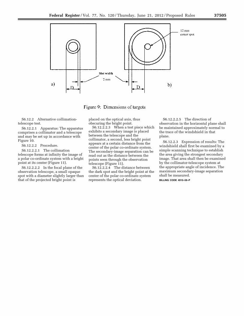
37505 Federal Register / Vol. 77, No. 120 / Thursday, June 21, 2012 / Proposed Rules
S6.12.2 Alternative collimation- telescope test.
S6.12.2.1 Apparatus: The apparatus comprises a collimator and a telescope and may be set up in accordance with Figure 10.
S6.12.2.2 Procedure. S6.12.2.2.1 The collimation
telescope forms at infinity the image of a polar co-ordinate system with a bright point at its center (Figure 11).
S6.12.2.2.2 In the focal plane of the observation telescope, a small opaque spot with a diameter slightly larger than that of the projected bright point is
placed on the optical axis, thus obscuring the bright point.
S6.12.2.2.3 When a test piece which exhibits a secondary image is placed between the telescope and the collimator, a second, less bright point appears at a certain distance from the center of the polar co-ordinate system. The secondary-image separation can be read out as the distance between the points seen through the observation telescope (Figure 11).
S6.12.2.2.4 The distance between the dark spot and the bright point at the center of the polar co-ordinate system represents the optical deviation.
S6.12.2.2.5 The direction of observation in the horizontal plane shall be maintained approximately normal to the trace of the windshield in that plane.
S6.12.2.3 Expression of results: The windshield shall first be examined by a simple scanning technique to establish the area giving the strongest secondary image. That area shall then be examined by the collimator-telescope system at the appropriate angle of incidence. The maximum secondary-image separation shall be measured. BILLING CODE 4910–59–P
VerDate Mar<15>2010 18:50 Jun 20, 2012 Jkt 226001 PO 00000 Frm 00029 Fmt 4701 Sfmt 4702 E:\FR\FM\21JNP2.SGM 21JNP2 EP
21JN
12.0
10<
/GP
H>
TK
ELL
EY
on
DS
K3S
PT
VN
1PR
OD
with
PR
OP
OS
ALS
2

37506 Federal Register / Vol. 77, No. 120 / Thursday, June 21, 2012 / Proposed Rules
VerDate Mar<15>2010 18:50 Jun 20, 2012 Jkt 226001 PO 00000 Frm 00030 Fmt 4701 Sfmt 4725 E:\FR\FM\21JNP2.SGM 21JNP2 EP
21JN
12.0
11<
/GP
H>
TK
ELL
EY
on
DS
K3S
PT
VN
1PR
OD
with
PR
OP
OS
ALS
2

37507 Federal Register / Vol. 77, No. 120 / Thursday, June 21, 2012 / Proposed Rules
S6.12.4 Test pieces: The test pieces shall be windshields.
S6.13 Fire resistance test procedure. S6.13.1 Apparatus.
S6.13.1.1 Combustion chamber.
S6.13.1.1.1 The combustion chamber is illustrated by Figure 12,
having the dimensions given in Figure 13.
VerDate Mar<15>2010 18:50 Jun 20, 2012 Jkt 226001 PO 00000 Frm 00031 Fmt 4701 Sfmt 4702 E:\FR\FM\21JNP2.SGM 21JNP2 EP
21JN
12.0
12<
/GP
H>
TK
ELL
EY
on
DS
K3S
PT
VN
1PR
OD
with
PR
OP
OS
ALS
2

37508 Federal Register / Vol. 77, No. 120 / Thursday, June 21, 2012 / Proposed Rules
VerDate Mar<15>2010 18:50 Jun 20, 2012 Jkt 226001 PO 00000 Frm 00032 Fmt 4701 Sfmt 4725 E:\FR\FM\21JNP2.SGM 21JNP2 EP
21JN
12.0
13<
/GP
H>
TK
ELL
EY
on
DS
K3S
PT
VN
1PR
OD
with
PR
OP
OS
ALS
2

37509 Federal Register / Vol. 77, No. 120 / Thursday, June 21, 2012 / Proposed Rules
S6.13.1.1.2 The combustion chamber is constructed of stainless steel.
S6.13.1.1.3 The front of the chamber contains a flame-resistant observation
window, which may cover the entire front and which can be constructed as an access panel.
S6.13.1.1.4 The bottom of the chamber has vent holes, and the top has a vent slot all around.
VerDate Mar<15>2010 18:50 Jun 20, 2012 Jkt 226001 PO 00000 Frm 00033 Fmt 4701 Sfmt 4702 E:\FR\FM\21JNP2.SGM 21JNP2 EP
21JN
12.0
14<
/GP
H>
TK
ELL
EY
on
DS
K3S
PT
VN
1PR
OD
with
PR
OP
OS
ALS
2

37510 Federal Register / Vol. 77, No. 120 / Thursday, June 21, 2012 / Proposed Rules
S6.13.1.2 Sample holder. S6.13.1.2.1 The sample holder
consists of two U-shaped metal plates or
frames of corrosion-proof material. Dimensions are given in Figure 15.
S6.13.1.2.2 The lower plate is equipped with pins and the upper one with corresponding holes, in order to ensure a consistent holding of the sample. The pins also serve as
measuring points at the beginning and end of the burning distance.
S6.13.1.2.3 A support shall be provided in the form of heat-resistant wires 0.25 mm (0.01 in) in diameter spanning the frame at 25 mm (0.94 in)
intervals over the bottom U-shaped frame (Figure 16).
VerDate Mar<15>2010 18:50 Jun 20, 2012 Jkt 226001 PO 00000 Frm 00034 Fmt 4701 Sfmt 4702 E:\FR\FM\21JNP2.SGM 21JNP2 EP
21JN
12.0
15<
/GP
H>
EP
21JN
12.0
16<
/GP
H>
TK
ELL
EY
on
DS
K3S
PT
VN
1PR
OD
with
PR
OP
OS
ALS
2
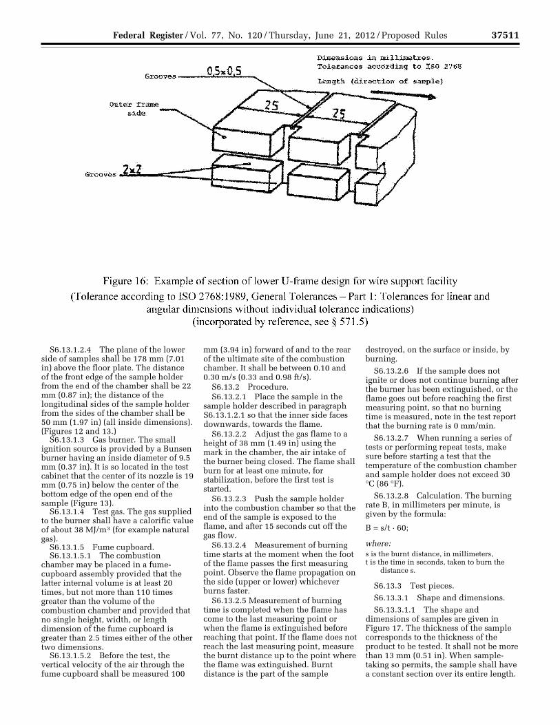
37511 Federal Register / Vol. 77, No. 120 / Thursday, June 21, 2012 / Proposed Rules
S6.13.1.2.4 The plane of the lower side of samples shall be 178 mm (7.01 in) above the floor plate. The distance of the front edge of the sample holder from the end of the chamber shall be 22 mm (0.87 in); the distance of the longitudinal sides of the sample holder from the sides of the chamber shall be 50 mm (1.97 in) (all inside dimensions). (Figures 12 and 13.)
S6.13.1.3 Gas burner. The small ignition source is provided by a Bunsen burner having an inside diameter of 9.5 mm (0.37 in). It is so located in the test cabinet that the center of its nozzle is 19 mm (0.75 in) below the center of the bottom edge of the open end of the sample (Figure 13).
S6.13.1.4 Test gas. The gas supplied to the burner shall have a calorific value of about 38 MJ/m3 (for example natural gas).
S6.13.1.5 Fume cupboard. S6.13.1.5.1 The combustion
chamber may be placed in a fume- cupboard assembly provided that the latter internal volume is at least 20 times, but not more than 110 times greater than the volume of the combustion chamber and provided that no single height, width, or length dimension of the fume cupboard is greater than 2.5 times either of the other two dimensions.
S6.13.1.5.2 Before the test, the vertical velocity of the air through the fume cupboard shall be measured 100
mm (3.94 in) forward of and to the rear of the ultimate site of the combustion chamber. It shall be between 0.10 and 0.30 m/s (0.33 and 0.98 ft/s).
S6.13.2 Procedure. S6.13.2.1 Place the sample in the
sample holder described in paragraph S6.13.1.2.1 so that the inner side faces downwards, towards the flame.
S6.13.2.2 Adjust the gas flame to a height of 38 mm (1.49 in) using the mark in the chamber, the air intake of the burner being closed. The flame shall burn for at least one minute, for stabilization, before the first test is started.
S6.13.2.3 Push the sample holder into the combustion chamber so that the end of the sample is exposed to the flame, and after 15 seconds cut off the gas flow.
S6.13.2.4 Measurement of burning time starts at the moment when the foot of the flame passes the first measuring point. Observe the flame propagation on the side (upper or lower) whichever burns faster.
S6.13.2.5 Measurement of burning time is completed when the flame has come to the last measuring point or when the flame is extinguished before reaching that point. If the flame does not reach the last measuring point, measure the burnt distance up to the point where the flame was extinguished. Burnt distance is the part of the sample
destroyed, on the surface or inside, by burning.
S6.13.2.6 If the sample does not ignite or does not continue burning after the burner has been extinguished, or the flame goes out before reaching the first measuring point, so that no burning time is measured, note in the test report that the burning rate is 0 mm/min.
S6.13.2.7 When running a series of tests or performing repeat tests, make sure before starting a test that the temperature of the combustion chamber and sample holder does not exceed 30 °C (86 °F).
S6.13.2.8 Calculation. The burning rate B, in millimeters per minute, is given by the formula:
B = s/t · 60;
where: s is the burnt distance, in millimeters, t is the time in seconds, taken to burn the
distance s.
S6.13.3 Test pieces. S6.13.3.1 Shape and dimensions. S6.13.3.1.1 The shape and
dimensions of samples are given in Figure 17. The thickness of the sample corresponds to the thickness of the product to be tested. It shall not be more than 13 mm (0.51 in). When sample- taking so permits, the sample shall have a constant section over its entire length.
VerDate Mar<15>2010 18:50 Jun 20, 2012 Jkt 226001 PO 00000 Frm 00035 Fmt 4701 Sfmt 4702 E:\FR\FM\21JNP2.SGM 21JNP2 EP
21JN
12.0
17<
/GP
H>
TK
ELL
EY
on
DS
K3S
PT
VN
1PR
OD
with
PR
OP
OS
ALS
2
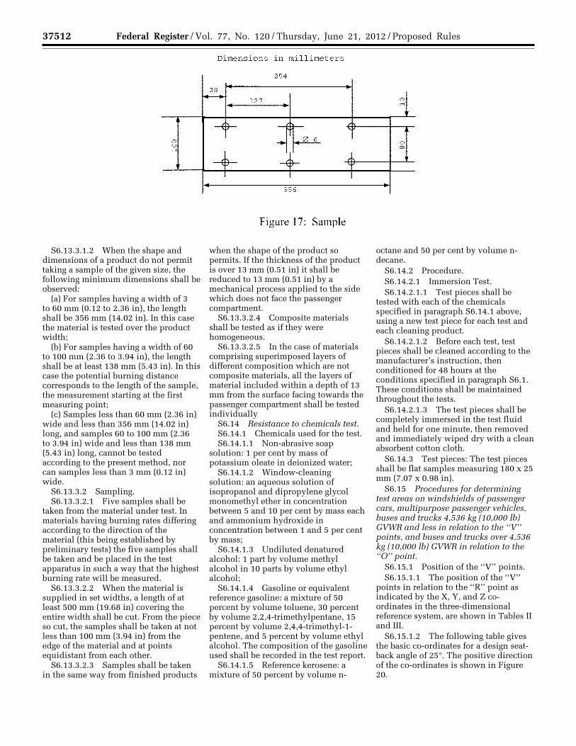
37512 Federal Register / Vol. 77, No. 120 / Thursday, June 21, 2012 / Proposed Rules
S6.13.3.1.2 When the shape and dimensions of a product do not permit taking a sample of the given size, the following minimum dimensions shall be observed:
(a) For samples having a width of 3 to 60 mm (0.12 to 2.36 in), the length shall be 356 mm (14.02 in). In this case the material is tested over the product width;
(b) For samples having a width of 60 to 100 mm (2.36 to 3.94 in), the length shall be at least 138 mm (5.43 in). In this case the potential burning distance corresponds to the length of the sample, the measurement starting at the first measuring point;
(c) Samples less than 60 mm (2.36 in) wide and less than 356 mm (14.02 in) long, and samples 60 to 100 mm (2.36 to 3.94 in) wide and less than 138 mm (5.43 in) long, cannot be tested according to the present method, nor can samples less than 3 mm (0.12 in) wide.
S6.13.3.2 Sampling. S6.13.3.2.1 Five samples shall be
taken from the material under test. In materials having burning rates differing according to the direction of the material (this being established by preliminary tests) the five samples shall be taken and be placed in the test apparatus in such a way that the highest burning rate will be measured.
S6.13.3.2.2 When the material is supplied in set widths, a length of at least 500 mm (19.68 in) covering the entire width shall be cut. From the piece so cut, the samples shall be taken at not less than 100 mm (3.94 in) from the edge of the material and at points equidistant from each other.
S6.13.3.2.3 Samples shall be taken in the same way from finished products
when the shape of the product so permits. If the thickness of the product is over 13 mm (0.51 in) it shall be reduced to 13 mm (0.51 in) by a mechanical process applied to the side which does not face the passenger compartment.
S6.13.3.2.4 Composite materials shall be tested as if they were homogeneous.
S6.13.3.2.5 In the case of materials comprising superimposed layers of different composition which are not composite materials, all the layers of material included within a depth of 13 mm from the surface facing towards the passenger compartment shall be tested individually
S6.14 Resistance to chemicals test. S6.14.1 Chemicals used for the test. S6.14.1.1 Non-abrasive soap
solution: 1 per cent by mass of potassium oleate in deionized water;
S6.14.1.2 Window-cleaning solution: an aqueous solution of isopropanol and dipropylene glycol monomethyl ether in concentration between 5 and 10 per cent by mass each and ammonium hydroxide in concentration between 1 and 5 per cent by mass;
S6.14.1.3 Undiluted denatured alcohol: 1 part by volume methyl alcohol in 10 parts by volume ethyl alcohol;
S6.14.1.4 Gasoline or equivalent reference gasoline: a mixture of 50 percent by volume toluene, 30 percent by volume 2,2,4-trimethylpentane, 15 percent by volume 2,4,4-trimethyl-1- pentene, and 5 percent by volume ethyl alcohol. The composition of the gasoline used shall be recorded in the test report.
S6.14.1.5 Reference kerosene: a mixture of 50 percent by volume n-
octane and 50 per cent by volume n- decane.
S6.14.2 Procedure. S6.14.2.1 Immersion Test. S6.14.2.1.1 Test pieces shall be
tested with each of the chemicals specified in paragraph S6.14.1 above, using a new test piece for each test and each cleaning product.
S6.14.2.1.2 Before each test, test pieces shall be cleaned according to the manufacturer’s instruction, then conditioned for 48 hours at the conditions specified in paragraph S6.1. These conditions shall be maintained throughout the tests.
S6.14.2.1.3 The test pieces shall be completely immersed in the test fluid and held for one minute, then removed and immediately wiped dry with a clean absorbent cotton cloth.
S6.14.3 Test pieces: The test pieces shall be flat samples measuring 180 x 25 mm (7.07 x 0.98 in).
S6.15 Procedures for determining test areas on windshields of passenger cars, multipurpose passenger vehicles, buses and trucks 4,536 kg (10,000 lb) GVWR and less in relation to the ‘‘V’’ points, and buses and trucks over 4,536 kg (10,000 lb) GVWR in relation to the ‘‘O’’ point.
S6.15.1 Position of the ‘‘V’’ points. S6.15.1.1 The position of the ‘‘V’’
points in relation to the ‘‘R’’ point as indicated by the X, Y, and Z co- ordinates in the three-dimensional reference system, are shown in Tables II and III.
S6.15.1.2 The following table gives the basic co-ordinates for a design seat- back angle of 25°. The positive direction of the co-ordinates is shown in Figure 20.
VerDate Mar<15>2010 18:50 Jun 20, 2012 Jkt 226001 PO 00000 Frm 00036 Fmt 4701 Sfmt 4702 E:\FR\FM\21JNP2.SGM 21JNP2 EP
21JN
12.0
18<
/GP
H>
TK
ELL
EY
on
DS
K3S
PT
VN
1PR
OD
with
PR
OP
OS
ALS
2

37513 Federal Register / Vol. 77, No. 120 / Thursday, June 21, 2012 / Proposed Rules
TABLE TO S6.15.1.2
V Point A b c(d)
V1 ............................................................................................................. 68 mm (2.68 in) ......... ¥5 mm (¥0.2 in). ..... 665 mm (26.18 in) V2 ............................................................................................................. 68 mm (2.68 in) ......... ¥5 mm (¥0.2 in). ..... 589 mm (12.19 in)
S6.15.1.3 Correction for design seat- back angles other than 25 degrees.
S6.15.1.3.1 The following table shows the further corrections to be
made to the X and Z co-ordinates of each ‘‘V’’ point when the design seat- back angle is not 25°. The positive
direction of the co-ordinates is shown in Figure 20.
TABLE TO S6.15.1.3.1
Seat-back angle (in °)
Horizontal co-ordinates X
mm (in)
Vertical co-ordinates Z
mm (in)
Seat-back angle (in °)
Horizontal co-ordinates X
mm (in)
Vertical co-ordinates Z
mm (in)
5 ....................................................................... ¥186 (¥7.32) 28 (1.1) 23 ¥18 (¥0.71) 5 (0.2) 6 ....................................................................... ¥177 (¥6.97) 27 (1.06) 24 ¥9 (¥0.35) 3 (0.12) 7 ....................................................................... ¥167 (¥6.57) 27 (1.06) 25 0 (0) 0 (0) 8 ....................................................................... ¥157 (¥6.18) 27 (1.06) 26 9 (0.35) ¥3 (¥0.12) 9 ....................................................................... ¥147 (¥5.79) 26 (1.02) 27 17 (0.67) ¥5 (¥0.2) 10 ..................................................................... ¥ 137 (¥5.39) 25 (0.98) 28 26 (1.02) ¥8 (¥0.31) 11 ..................................................................... ¥128 (¥5.04) 24 (0.94) 29 34 (1.34) ¥11 (¥0.43) 12 ..................................................................... ¥118 (¥4.65) 23 (0.91) 30 43 (1.7) ¥14 (¥0.55) 13 ..................................................................... ¥109 (¥4.29) 22 (0.87) 31 51 (2.01) ¥18 (¥0.71) 14 ..................................................................... ¥99 (¥3.9) 21 (0.83) 32 59 (2.32) ¥21 (¥0.83) 15 ..................................................................... ¥90 (¥3.54) 20 (0.79) 33 67 (2.64) ¥24 (¥0.94) 16 ..................................................................... ¥81 (¥3.19) 18 (0.71) 34 76 (3) ¥28 (¥1.1) 17 ..................................................................... ¥72 (¥2.83) 17 (0.67) 35 84 (3.31) ¥32 (¥1.26) 18 ..................................................................... ¥62 (¥2.44) 15 (0.59) 36 92 (3.62) ¥35 (¥1.38) 19 ..................................................................... ¥53 (¥2.09) 13 (0.51) 37 100 (3.93) ¥39 (¥1.54) 20 ..................................................................... ¥44 (¥1.73) 11 (0.43) 38 108 (4.25) ¥43 (¥1.69) 21 ..................................................................... ¥35 (¥1.38) 9 (0.35) 39 115 (4.53) ¥48 (¥1.89) 22 ..................................................................... ¥26 (¥1.02) 7 (0.28) 40 123 (4.84) ¥52 (¥2.05)
S6.15.2 Position of the ‘‘O’’ point. S6.15.2.1 The eye-point ‘‘O’’ is the
point located 625 mm (26.61 in) above the R-point in the vertical plane parallel to the longitudinal median plane of the vehicle for which the windshield is intended, passing through the axis of the steering wheel.
S6.15.3 Test areas S6.15.3.1 The test areas shall be
determined as follows: S6.15.3.1.1 For optical distortion
and image separation measurement: (a) In case of passenger cars, multi-
purpose passenger vehicles, buses and trucks under 4536 kg (10,000 lb) GVWR according to paragraph S6.15.3.2.
(b) In case of buses and trucks over 4536 kg (10,000 lb) GVWR vehicles according to paragraph S6.15.3.3.
S6.15.3.1.2 For the measurement of the light transmittance in the transparent area of the windshield according to paragraph S6.15.3.4.
S6.15.3.2 Determination of two test areas for passenger cars, multipurpose passenger cars, buses and trucks 4,536 kg (10,000 lb) GVWR and less vehicles using the ‘‘V’’ points.
S6.15.3.2.1 Test area A is the area on the outer surface of the windshield bounded by the following four planes
extending forward from the ‘‘V’’ points (see Figure 18):
(a) A plane parallel to the Y axis passing through V1 and inclined upwards at 3 degrees from the X axis (Figure 18, plane 1);
(b) A plane parallel to the Y axis passing through V2 and inclined downwards at 1 degree from the X axis (Figure 18, plane 2);
(c) A vertical plane passing through V1 and V2 and inclined at 13 degrees to the left of the axis in the case of left- hand drive vehicles and to the right of the X axis in the case of right-hand drive vehicles (Figure 18, plane 3);
(d) A vertical plane passing through V1 and V2 and inclined at 20 degrees to the right of the X axis in the case of left- hand drive vehicles and to the left of the X axis in the case of right-hand drive vehicles (Figure 18, plane 4).
S6.15.3.2.2 The ‘‘extended test area A’’ is Zone A, extended to the median plane of the vehicle, and in the corresponding part of the windshield symmetrical to it about the longitudinal median plane of the vehicle, and also in the reduced test area B according to paragraph S6.15.3.2.4.
S6.15.3.2.3 Test area B is the area of the outer surface of the windshield
bounded by the intersection of the following four planes (see Figure 19):
(a) A plane inclined upward from the X axis at 7 degrees, passing through V1 and parallel to the Y axis (Figure 19, plane 5);
(b) A plane inclined downward from the X axis at 5 degrees, passing through V2 and parallel to the Y axis (Figure 19, plane 6);
(c) A vertical plane passing through V1 and V2 and forming an angle of 17 degrees to the left of the X axis in the case of left-hand drive vehicles and to the right of the X axis in the case of right-hand drive vehicles (Figure 19, plane 7);
(d) A plane symmetrical with respect to the plane 7 in relation to the longitudinal median plane of the vehicle (Figure 19, plane 8).
S6.15.3.2.4 The ‘‘reduced test area B’’ is test area B with the exclusion of the following areas (taking into account the fact that the data points as defined under paragraph S6.15.3.2.5 shall be located in the transparent area, see Figures 19 and 20):
S6.15.3.2.4.1 The test area A defined under paragraph S6.15.3.2.1, extended according to paragraph S6.15.3.2.2.
VerDate Mar<15>2010 18:50 Jun 20, 2012 Jkt 226001 PO 00000 Frm 00037 Fmt 4701 Sfmt 4702 E:\FR\FM\21JNP2.SGM 21JNP2TK
ELL
EY
on
DS
K3S
PT
VN
1PR
OD
with
PR
OP
OS
ALS
2
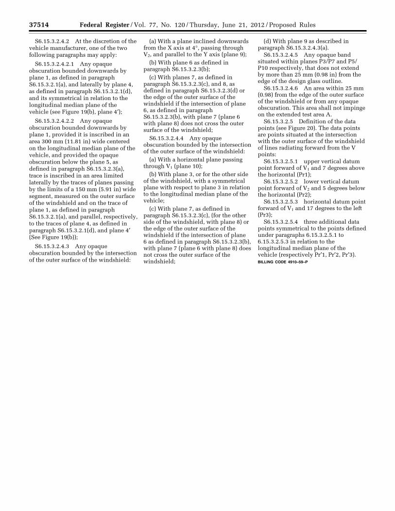
37514 Federal Register / Vol. 77, No. 120 / Thursday, June 21, 2012 / Proposed Rules
S6.15.3.2.4.2 At the discretion of the vehicle manufacturer, one of the two following paragraphs may apply:
S6.15.3.2.4.2.1 Any opaque obscuration bounded downwards by plane 1, as defined in paragraph S6.15.3.2.1(a), and laterally by plane 4, as defined in paragraph S6.15.3.2.1(d), and its symmetrical in relation to the longitudinal median plane of the vehicle (see Figure 19(b), plane 4′);
S6.15.3.2.4.2.2 Any opaque obscuration bounded downwards by plane 1, provided it is inscribed in an area 300 mm (11.81 in) wide centered on the longitudinal median plane of the vehicle, and provided the opaque obscuration below the plane 5, as defined in paragraph S6.15.3.2.3(a), trace is inscribed in an area limited laterally by the traces of planes passing by the limits of a 150 mm (5.91 in) wide segment, measured on the outer surface of the windshield and on the trace of plane 1, as defined in paragraph S6.15.3.2.1(a), and parallel, respectively, to the traces of plane 4, as defined in paragraph S6.15.3.2.1(d), and plane 4′ (See Figure 19(b));
S6.15.3.2.4.3 Any opaque obscuration bounded by the intersection of the outer surface of the windshield:
(a) With a plane inclined downwards from the X axis at 4°, passing through V2, and parallel to the Y axis (plane 9);
(b) With plane 6 as defined in paragraph S6.15.3.2.3(b);
(c) With planes 7, as defined in paragraph S6.15.3.2.3(c), and 8, as defined in paragraph S6.15.3.2.3(d) or the edge of the outer surface of the windshield if the intersection of plane 6, as defined in paragraph S6.15.3.2.3(b), with plane 7 (plane 6 with plane 8) does not cross the outer surface of the windshield;
S6.15.3.2.4.4 Any opaque obscuration bounded by the intersection of the outer surface of the windshield:
(a) With a horizontal plane passing through V1 (plane 10);
(b) With plane 3, or for the other side of the windshield, with a symmetrical plane with respect to plane 3 in relation to the longitudinal median plane of the vehicle;
(c) With plane 7, as defined in paragraph S6.15.3.2.3(c), (for the other side of the windshield, with plane 8) or the edge of the outer surface of the windshield if the intersection of plane 6 as defined in paragraph S6.15.3.2.3(b), with plane 7 (plane 6 with plane 8) does not cross the outer surface of the windshield;
(d) With plane 9 as described in paragraph S6.15.3.2.4.3(a).
S6.15.3.2.4.5 Any opaque band situated within planes P3/P7 and P5/ P10 respectively, that does not extend by more than 25 mm (0.98 in) from the edge of the design glass outline.
S6.15.3.2.4.6 An area within 25 mm (0.98) from the edge of the outer surface of the windshield or from any opaque obscuration. This area shall not impinge on the extended test area A.
S6.15.3.2.5 Definition of the data points (see Figure 20). The data points are points situated at the intersection with the outer surface of the windshield of lines radiating forward from the V points:
S6.15.3.2.5.1 upper vertical datum point forward of V1 and 7 degrees above the horizontal (Pr1);
S6.15.3.2.5.2 lower vertical datum point forward of V2 and 5 degrees below the horizontal (Pr2);
S6.15.3.2.5.3 horizontal datum point forward of V1 and 17 degrees to the left (Pr3);
S6.15.3.2.5.4 three additional data points symmetrical to the points defined under paragraphs 6.15.3.2.5.1 to 6.15.3.2.5.3 in relation to the longitudinal median plane of the vehicle (respectively Pr′1, Pr′2, Pr′3). BILLING CODE 4910–59–P
VerDate Mar<15>2010 18:50 Jun 20, 2012 Jkt 226001 PO 00000 Frm 00038 Fmt 4701 Sfmt 4702 E:\FR\FM\21JNP2.SGM 21JNP2TK
ELL
EY
on
DS
K3S
PT
VN
1PR
OD
with
PR
OP
OS
ALS
2

37515 Federal Register / Vol. 77, No. 120 / Thursday, June 21, 2012 / Proposed Rules
VerDate Mar<15>2010 18:50 Jun 20, 2012 Jkt 226001 PO 00000 Frm 00039 Fmt 4701 Sfmt 4725 E:\FR\FM\21JNP2.SGM 21JNP2 EP
21JN
12.0
19<
/GP
H>
TK
ELL
EY
on
DS
K3S
PT
VN
1PR
OD
with
PR
OP
OS
ALS
2

37516 Federal Register / Vol. 77, No. 120 / Thursday, June 21, 2012 / Proposed Rules
VerDate Mar<15>2010 18:50 Jun 20, 2012 Jkt 226001 PO 00000 Frm 00040 Fmt 4701 Sfmt 4725 E:\FR\FM\21JNP2.SGM 21JNP2 EP
21JN
12.0
20<
/GP
H>
TK
ELL
EY
on
DS
K3S
PT
VN
1PR
OD
with
PR
OP
OS
ALS
2
37517 Federal Register / Vol. 77, No. 120 / Thursday, June 21, 2012 / Proposed Rules
VerDate Mar<15>2010 18:50 Jun 20, 2012 Jkt 226001 PO 00000 Frm 00041 Fmt 4701 Sfmt 4725 E:\FR\FM\21JNP2.SGM 21JNP2 EP
21JN
12.0
21<
/GP
H>
TK
ELL
EY
on
DS
K3S
PT
VN
1PR
OD
with
PR
OP
OS
ALS
2

37518 Federal Register / Vol. 77, No. 120 / Thursday, June 21, 2012 / Proposed Rules
S6.15.3.3 Determination of the Test Areas for buses and trucks over 4,536 kg (10,000 lb) GVWR using the ‘‘O’’ Point.
S6.15.3.3.1 The straight line OQ which is the horizontal straight line passing through the eye point ‘‘O’’ and perpendicular to the median longitudinal plane of the vehicle.
S6.15.3.3.2 Zone I is the zone determined by the intersection of the
windshield with the four planes defined below:
(a) P1: a vertical plane passing through 0 and forming an angle of 15 degrees to the left of the median longitudinal plane of the vehicle;
(b) P2: a vertical plane symmetrical to P1 about the median longitudinal plane of the vehicle. If this is not possible (in the absence of a symmetrical median longitudinal plane, for instance) P2
shall be the plane symmetrical to P1 about the longitudinal plane of the vehicle passing through point O.
(c) P3: a plane passing through a transverse horizontal line containing O and forming an angle of 10 degrees above the horizontal plane;
(d) P4: a plane passing through a transverse horizontal line containing O and forming an angle of 8 degrees below the horizontal plane.
VerDate Mar<15>2010 18:50 Jun 20, 2012 Jkt 226001 PO 00000 Frm 00042 Fmt 4701 Sfmt 4702 E:\FR\FM\21JNP2.SGM 21JNP2 EP
21JN
12.0
22<
/GP
H>
TK
ELL
EY
on
DS
K3S
PT
VN
1PR
OD
with
PR
OP
OS
ALS
2
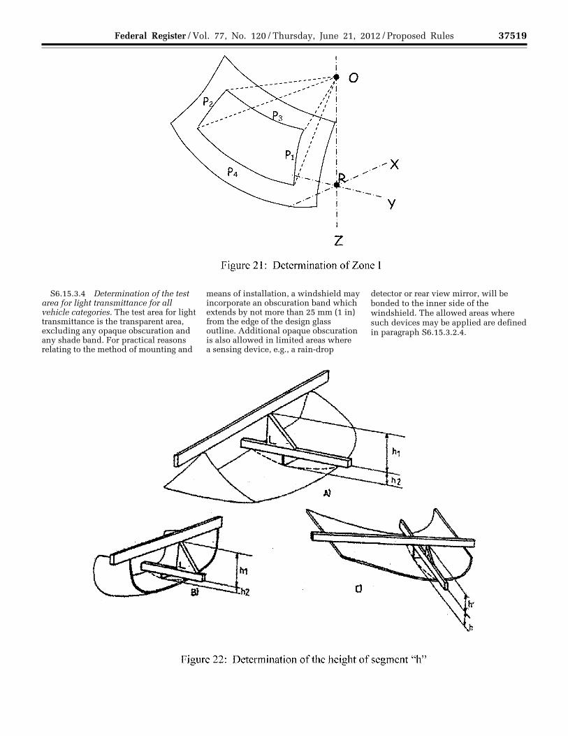
37519 Federal Register / Vol. 77, No. 120 / Thursday, June 21, 2012 / Proposed Rules
S6.15.3.4 Determination of the test area for light transmittance for all vehicle categories. The test area for light transmittance is the transparent area, excluding any opaque obscuration and any shade band. For practical reasons relating to the method of mounting and
means of installation, a windshield may incorporate an obscuration band which extends by not more than 25 mm (1 in) from the edge of the design glass outline. Additional opaque obscuration is also allowed in limited areas where a sensing device, e.g., a rain-drop
detector or rear view mirror, will be bonded to the inner side of the windshield. The allowed areas where such devices may be applied are defined in paragraph S6.15.3.2.4.
VerDate Mar<15>2010 18:50 Jun 20, 2012 Jkt 226001 PO 00000 Frm 00043 Fmt 4701 Sfmt 4725 E:\FR\FM\21JNP2.SGM 21JNP2 EP
21JN
12.0
23<
/GP
H>
EP
21JN
12.0
24<
/GP
H>
TK
ELL
EY
on
DS
K3S
PT
VN
1PR
OD
with
PR
OP
OS
ALS
2

37520 Federal Register / Vol. 77, No. 120 / Thursday, June 21, 2012 / Proposed Rules
S6.16 Measurement of the height of segment and position of the points of impact.
S6.16.1 In the case of glazing having a simple curvature, the height of segment will be equal to: h1 maximum.
S6.16.2 In the case of glazing having a double curvature, the height of segment will be equal to: h1 maximum + h2 maximum.
VerDate Mar<15>2010 18:50 Jun 20, 2012 Jkt 226001 PO 00000 Frm 00044 Fmt 4701 Sfmt 4725 E:\FR\FM\21JNP2.SGM 21JNP2 EP
21JN
12.0
25<
/GP
H>
TK
ELL
EY
on
DS
K3S
PT
VN
1PR
OD
with
PR
OP
OS
ALS
2

37521 Federal Register / Vol. 77, No. 120 / Thursday, June 21, 2012 / Proposed Rules
Issued on June 7, 2012. Christopher J. Bonanti, Associate Administrator for Rulemaking. [FR Doc. 2012–14996 Filed 6–20–12; 8:45 am]
BILLING CODE 4910–59–C
VerDate Mar<15>2010 18:50 Jun 20, 2012 Jkt 226001 PO 00000 Frm 00045 Fmt 4701 Sfmt 9990 E:\FR\FM\21JNP2.SGM 21JNP2TK
ELL
EY
on
DS
K3S
PT
VN
1PR
OD
with
PR
OP
OS
ALS
2