DEPARTMENT OF THE ARMY TECHNICAL MANUAL …r-390a.net/TM-11-5820-358-20.pdf · WARNING DANGEROUS...
57
DEPARTMENT OF THE ARMY TECHNICAL MANUAL TM 11-5820-358-20 DEPARTMENT OF THE AIR FORCE TECHNICAL ORDER TO 31R1-2URR-442 ORGANIZATIONAL MAINTENANCE MANUAL RADIO RECEIVER R-390A /URR This reprint includes all changes in effect at the time of publication; changes 2 through 4. DEPARTMENTS OF THE ARMY AND THE AIR FORCE 10 FEBRUARY 1961
Transcript of DEPARTMENT OF THE ARMY TECHNICAL MANUAL …r-390a.net/TM-11-5820-358-20.pdf · WARNING DANGEROUS...

DEPARTMENT OF THE ARMY TECHNICAL MANUAL TM 11-5820-358-20
DEPARTMENT OF THE AIR FORCE TECHNICAL ORDER TO 31R1-2URR-442
ORGANIZATIONAL MAINTENANCE
MANUAL
RADIO RECEIVER R-390A /URR
This reprint includes all changes in effect at thetime of publication; changes 2 through 4.
DEPARTMENTS OF THE ARMY AND THE AIR FORCE
10 FEBRUARY 1961
WARNING
DANGEROUS VOLTAGES EXISTIN THIS EQUIPMENT
Be careful when working on the 240-volt power supply and the circuits connected to it, or on the155/280-volt ac line connections Before connecting the receiver to an ac source, be sure that thechassis is connected to the same ground " the ac source.
DON'T TAKE CHANCES!

Change in force: C2, C 3, and C 4TM 11-5820-35820
TO 31R1-2URR-442C4
CHANGE DEPARTMENTS OF THE ARMYAND THE AIR FORCE
No. 4 WASHINGTON, DC, 29 February 1980
Organizational Maintenance ManualRADIO RECEIVER R-390A/URR
(NSN 5820-00-538-7555)
TM 11-5820-358-20, 10 February 1961, is changed as follows:The title is changed to read as shown above.
Page 3. Paragraph 1.1 is superseded as follows:
1.1. Indexes of Publicationsa. DA Pam 310-4. Refer to the latest issue of DA
Pam 310-4 to determine whether there are new editions,changes or additional publications pertaining to theequipment.
b. DA Pam 310-7. Refer to DA Pam 310-7 todetermine whether there are modification work orders(MWO's) pertaining to the equipment.
Paragraph 2 is superseded as follows:
2. Maintenance Forms, Records and Reportsa. Reports of Maintenance and Unsatisfactory
Equipment. Department of the Army forms andprocedures used for equipment maintenance will bethose prescribed by TM 38-750, The Army MaintenanceManagement System (TAMMS) (Army). Air Forcepersonnel will use AFM 66-1 for maintenance reportingand TO 00-35D54 for unsatisfactory equipmentreporting.
b. Report of Packaging and Handling Deficiencies.Fill out and forward DD Form 6 (PackagingImprovement Report) as prescribed in AR 700-58/NAVSUPINST 4030.29/AFR 7113/MCO P4030.29A,and DLAR 4145.8.
c. Discrepancy in Shipment Report (DISREP)(GSF 361). Fill out and forward Discrepancy inShipment Report (DISREP) (SF 361) as prescribed inAR 55-38/NAVSUPINST 4610.33B/ AFR 75-18/MCOP4610.19C and DLAR 4500.15.
Paragraphs 2.1, 2.2, 2.3, and 2.4 are addedafter paragraph 2.
2.1. Destruction of Army MaterielDemolition and destruction of electronic equipment willbe under the direction of the commander and inaccordance with TM 750-244-2.
2.2. Administrative StorageFor procedures, forms, and records, and inspectionsrequired during administrative storage of this equipment,refer to TM 740-90-1.
2.3. Reporting Errors and Recommending Improvements
a. You can help improve this manual. If you findany mistakes or if you know of a way to improve theprocedures, please let us know. Mail your letter or DAForm 2028 (Recommended Changes to Publicationsand Blank Forms) direct to: Commander, US ArmyCommunications and Electronics Materiel ReadinessCommand, ATTN: DRSEL-ME-MQ, Fort Monmouth, NJ07703.
b. For Air Force, submit AFTO Form 22 (TechnicalOrder System Publication Improvement Report andReply) in accordance with paragraph 6-5, Section VI,TO 00-5-1. Forward direct to prime ALC/MST.
c. In either case, a reply will be furnished direct toyou.
2.4. Reporting Equipment Improvement Recommendations (EIR)
a. Army. If your Radio Receiver R-390A/URRneeds improvement, let us know. Send us an
1
EIR. You, the user, are the only one who can tell uswhat you don't like about your equipment. Let us knowwhy you don't like the design. Tell us why a procedureis hard to perform. Put it on an SF 368 (QualityDeficiency Report). Mail it to Commander, US ArmyCommunications and Electronics Materiel ReadinessCommand,
ATTN: DRSEL-ME-MQ, Fort Monmouth, NJ 07703.We'll send you a reply.
b. Air Force. Air Force personnel are encouragedto submit EIR's in accordance with AFM 900-4.
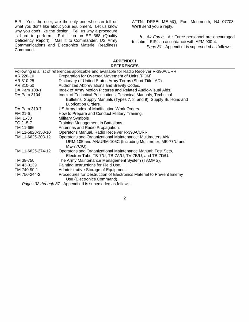
Page 31. Appendix I is superseded as follows:
APPENDIX IREFERENCES
Following is a list of references applicable and available for Radio Receiver R-390A/URR.AR 220-10 Preparation for Oversea Movement of Units (POM).AR 310-25 Dictionary of United States Army Terms (Short Title: AD).AR 310-50 Authorized Abbreviations and Brevity Codes.DA Pam 108-1 Index of Army Motion Pictures and Related Audio-Visual Aids.DA Pam 3104 Index of Technical Publications: Technical Manuals, Technical
Bulletins, Supply Manuals (Types 7, 8, and 9), Supply Bulletins andLubrication Orders.
DA Pam 310-7 US Army Index of Modification Work Orders.FM 21-6 How to Prepare and Conduct Military Training.FM '1.-30 Military SymbolsTC 2.-5-7 Training Management in Battalions.TM 11-666 Antennas and Radio Propagation.TM 11-5820-358-10 Operator's Manual, Radio Receiver R-390A/URR.TM 11-6625-203-12 Operator's and Organizational Maintenance: Multimeters AN/
URM-105 and AN/URM-105C (Including Multimeter, ME-77/U andME-77C/U).
TM 11-6625-274-12 Operator's and Organizational Maintenance Manual: Test Sets,Electron Tube TB-7/U, TB-7A/U, TV-7B/U, and TB-7D/U.
TM 38-750 The Army Maintenance Management System (TAMMS).TM 43-0139 Painting Instructions for Field Use.TM 740-90-1 Administrative Storage of Equipment.TM 750-244-2 Procedures for Destruction of Electronics Materiel to Prevent Enemy
Use (Electronics Command).Pages 32 through 37. Appendix II is superseded as follows:
2

APPENDIX IIIMAINTENANCE ALLOCATION
Section I. INTRODUCTION
A2-1. GeneralThis appendix provides a summary of the maintenanceoperations for Radio Receiver R-390AfURR. Itauthorizes categories of maintenance for specificmaintenance functions on repairable items andcomponents and the tools and equipment required toperform each function. This appendix may be used asan aid in planning maintenance operations.
A2-2. Maintenance FunctionMaintenance functions will be limited to and defined asfollows:
a. Inspect. To determine the serviceability of anitem by comparing its physical, mechanical, and/orelectrical characteristics with established standardsthrough examination.
b. Test. To verify serviceability and to detectincipient failure by measuring the mechanical orelectrical characteristics of an item and comparing thosecharacteristics with prescribed standards.
c. Service. Operations required periodically tokeep an item in proper operating condition; i.e., to clean(decontaminate), to preserve, to drain, to paint, or toreplenish fuel, lubricants, hydraulic fluids, orcompressed air supplies.
d. Adjust. To maintain, within prescribed limits, bybringing into proper or exact position, or by setting theoperating characteristics to the specified parameters.
e. Align. To adjust specified variable elements ofan item to bring about optimum or desired performance.
f. Calibrate. To determine and cause correctionsto be made or to be adjusted on instruments or testmeasuring and diagnostic equipments used in precisionmeasurement. Consists of comparisons of twoinstruments, one of which is a certified standard ofknown accuracy, to detect and adjust any discrepancy inthe accuracy of the instrument being compared.
g. Install. The act of emplacing, seating, or fixinginto position an item, part, module
(component or assembly) in a manner to allow theproper functioning of the equipment or system.
h. Replace. The act of substituting a serviceablelike type part, subassembly, or module (component orassembly) for an unserviceable counterpart.
i. Repair. The application of maintenanceservices (inspect, test, service, adjust, align, calibrate,replace) or other maintenance actions (welding,grinding, riveting, straightening, facing, remachining, orresurfacing) to restore serviceability to an item bycorrecting specific damage, fault, malfunction, or failurein a part, subassembly, module (component orassembly), end item, or system.
j. Overhaul. That maintenance effort(service/action) necessary to restore an item to acompletely serviceable/operational condition asprescribed by maintenance standards (i.e., DMWR) inappropriate technical publications. Overhaul is normallythe highest degree of maintenance performed by theArmy. Overhaul does not normally return an item to likenew condition.
k. Rebuild. Consists of those services/actionsnecessary for the restoration of unserviceableequipment to a like new condition in accordance withoriginal manufacturing standards. Rebuild is the highestdegree of materiel maintenance applied to Armyequipment. The rebuild operation includes the act ofreturning to zero those age measurements (hours,miles, etc.) considered in classifying Army equipments/components.A2-3. Column Entries
a. Column 1, Group Number. Column 1 lists groupnumbers, the purpose of which is to identifycomponents, assemblies, subassemblies, and moduleswith the next higher assembly.
b. Column 2, Component/Assembly. Column 2contains the noun names of components, assemblies,subassemblies, and modules for which
3
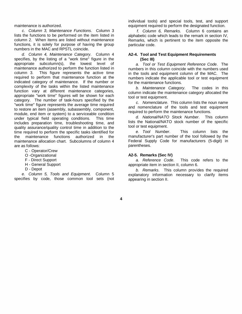
maintenance is authorized.c. Column 3, Maintenance Functions. Column 3
lists the functions to be performed on the item listed incolumn 2. When items are listed without maintenancefunctions, it is solely for purpose of having the groupnumbers in the MAC and RPSTL coincide.
d. Column 4, Maintenance Category. Column 4specifies, by the listing of a "work time" figure in theappropriate subcolumn(s), the lowest level ofmaintenance authorized to perform the function listed incolumn 3. This figure represents the active timerequired to perform that maintenance function at theindicated category of maintenance. If the number orcomplexity of the tasks within the listed maintenancefunction vary at different maintenance categories,appropriate "work time" figures will be shown for eachcategory. The number of task-hours specified by the"work time" figure represents the average time requiredto restore an item (assembly, subassembly, component,module, end item or system) to a serviceable conditionunder typical field operating conditions. This timeincludes preparation time, troubleshooting time, andquality assurance/quality control time in addition to thetime required to perform the specific tasks identified forthe maintenance functions authorized in themaintenance allocation chart. Subcolumns of column 4are as follows:
C - Operator/CrewO -OrganizationalF - Direct SupportH - General SupportD - Depot
e. Column 5, Tools and Equipment. Column 5specifies by code, those common tool sets (not
individual tools) and special tools, test, and supportequipment required to perform the designated function.
f. Column 6, Remarks. Column 6 contains analphabetic code which leads to the remark in section IV,Remarks, which is pertinent to the item opposite theparticular code.
A2-4. Tool and Test Equipment Requirements (Sec III)
a. Tool or Test Equipment Reference Code. Thenumbers in this column coincide with the numbers usedin the tools and equipment column of the MAC. Thenumbers indicate the applicable tool or test equipmentfor the maintenance functions.
b. Maintenance Category. The codes in thiscolumn indicate the maintenance category allocated thetool or test equipment.
c. Nomenclature. This column lists the noun nameand nomenclature of the tools and test equipmentrequired to perform the maintenance functions.
d. National/NATO Stock Number. This columnlists the National/NATO stock number of the specifictool or test equipment.
e. Tool Number. This column lists themanufacturer's part number of the tool followed by theFederal Supply Code for manufacturers (5-digit) inparentheses.
A2-5. Remarks (Sec IV)a. Reference Code. This code refers to the
appropriate item in section II, column 6.b. Remarks. This column provides the required
explanatory information necessary to clarify itemsappearing in section II.
4
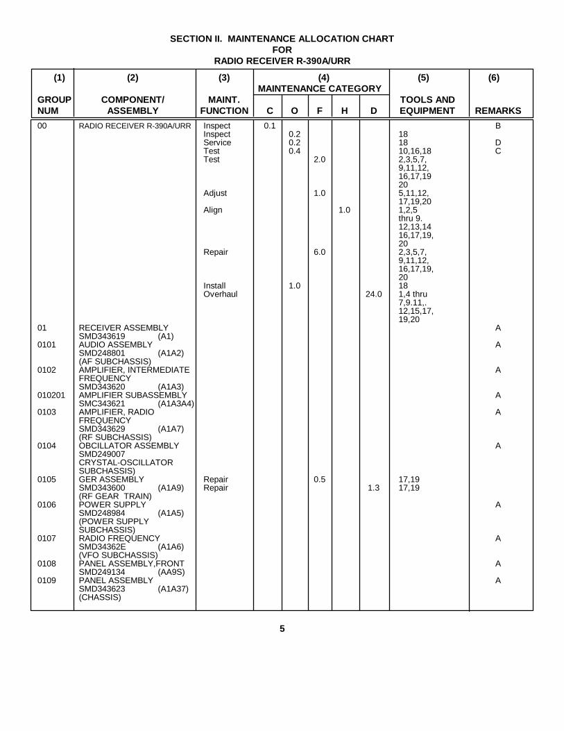
SECTION II. MAINTENANCE ALLOCATION CHARTFOR
RADIO RECEIVER R-390A/URR
(1) (2) (3) (4) (5) (6)MAINTENANCE CATEGORY
GROUP COMPONENT/ MAINT. TOOLS ANDNUM ASSEMBLY FUNCTION C O F H D EQUIPMENT REMARKS
00 RADIO RECEIVER R-390A/URR Inspect 0.1 BInspect 0.2 18Service 0.2 18 DTest 0.4 10,16,18 CTest 2.0 2,3,5,7,
9,11,12,16,17,1920
Adjust 1.0 5,11,12,17,19,20
Align 1.0 1,2,5thru 9.12,13,1416,17,19,20
Repair 6.0 2,3,5,7,9,11,12,16,17,19,20
Install 1.0 18Overhaul 24.0 1,4 thru
7,9.11,.12,15,17,19,20
01 RECEIVER ASSEMBLY ASMD343619 (A1)
0101 AUDIO ASSEMBLY ASMD248801 (A1A2)(AF SUBCHASSIS)
0102 AMPLIFIER, INTERMEDIATE AFREQUENCYSMD343620 (A1A3)
010201 AMPLIFIER SUBASSEMBLY ASMC343621 (A1A3A4)
0103 AMPLIFIER, RADIO AFREQUENCYSMD343629 (A1A7)(RF SUBCHASSIS)
0104 OBCILLATOR ASSEMBLY ASMD249007CRYSTAL-OSCILLATORSUBCHASSIS)
0105 GER ASSEMBLY Repair 0.5 17,19SMD343600 (A1A9) Repair 1.3 17,19(RF GEAR TRAIN)
0106 POWER SUPPLY ASMD248984 (A1A5)(POWER SUPPLYSUBCHASSIS)
0107 RADIO FREQUENCY ASMD34362E (A1A6)(VFO SUBCHASSIS)
0108 PANEL ASSEMBLY,FRONT ASMD249134 (AA9S)
0109 PANEL ASSEMBLY ASMD343623 (A1A37)(CHASSIS)
5

SECTION III. TOOL AND TEST EQUIPMENT REQUIREMENTSFOR
RADIO RECEIVER R-390A/URR
Tool or TestEquipment Maintenance National/NATO ToolRef Code Category Nomenclature Stock Number Number
1 H,D ANALYZER, SPECTRIM TS-723D/U 6625-00-668-94182 F,H AUDIO OSCILLATOR TS-382/U 6625-00-151-74793 F FREQUENCY METER AN/URM-32 6625-00-553-00604 D FREQUENCY METER AN/USN-26A 6625-00-543-13565 F,H,D GENERATOR, SIGNAL AN/URM-25D 6225-00-649-51936 H,D GENERATOR, SIGNAL AN/USN-44A 6625-00-539-96857 F,H,D HEADSET HS-30/U 5965-00-164-72598 H LIGHT ASSEMBLY, ELECTRIC NX-1292/PAQ 6695-00-378-54499 F,H,D MAINTENANCE KIT, ELECTRONIC EQUIPMENT 6625-00-557-5716
MK-288/URM10 O MULTIMETER AN/URM-105C 6625-00-999 628211 F.D MULTIMETER TS-352B/U 6625-00-553-014212 F.H,D MULTIMETER, ELECTRONIC TS-505/U 6625-00-243-056213 H OSCILLOSCOPE OS-8/U 6625-00-643-174014 H OUTPUT METER TS-585C/U 6625-00-244-050115 D TEST SET, ELECTON TUBE TV-2D/U 6625-00-669-026316 O,F,H TEST SET, ELECTRON TUBE TV-7D/U, 6625-00-820-006417 F,H,D TOOL KIT, ELECTRONIC EQUIPMENT TK-100/G 5180-00-605-007918 O TOOL KIT, ELECTRONIC EQUIPMENT TK-101/G 5180-00-064-517819 F,H,D TOOL KIT, ELECTRONIC EQUIPMENT TK-105/U 5180-00-610-817720 F,H,D VOLTMETER, ELECTRONIC ME-30E/U 6625-00-643-1670
6

SECTION IV. REMARKS
REFERENCECODE REMARKS
A ALL COMPONENTS WITH NO MAINTENANCE FUCTIONS INDICATED, ARE REPAIRED UNDERTHE NECT HIGHER ASSEMBLY/END ITEM.
B EXTERNAL VISUAL.
C PERFORMANCE CHECK.
D CRYSTALS, KNOBS, FUSES, LAMPS, TUBES REPLACED AT ORGANIZATIONAL LEVEL.
7

By Order of the Secretary of the Army:E. C. MEYER
General, United States ArmyOfficial: Chief Staff
J. C. PENNINGTONMajor General, United States Army
The Adjutant General
Distribution:To be distributed in accordance with DA Form 1261, Organizational Maintenance requirements for R390/URR, R-
390A/URR.

Changes In force: C 2 and C 3
TM 11-5820-358-20C3
CHANGE HEADQUARTERSDEPARTMENT OF THE ARMY
No. 3 WASHINGTON, DC, 3 April 1975
Organizational 'Maintenance ManualRADIO RECEIVER R-390/AURR
TM 11-5820-35820, 10 February 1961, is changed as follows:Inside front cover. Radiation warning is added after existing notice.
1
}
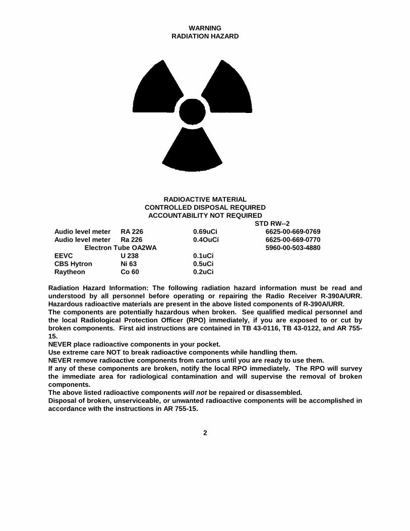
WARNINGRADIATION HAZARD
RADIOACTIVE MATERIALCONTROLLED DISPOSAL REQUIREDACCOUNTABILITY NOT REQUIRED
STD RW--2Audio level meter RA 226 0.69uCi 6625-00-669-0769Audio level meter Ra 226 0.4OuCi 6625-00-669-0770
Electron Tube OA2WA 5960-00-503-4880EEVC U 238 0.1uCiCBS Hytron Ni 63 0.5uCiRaytheon Co 60 0.2uCi
Radiation Hazard Information: The following radiation hazard information must be read andunderstood by all personnel before operating or repairing the Radio Receiver R-390A/URR.Hazardous radioactive materials are present in the above listed components of R-390A/URR.The components are potentially hazardous when broken. See qualified medical personnel andthe local Radiological Protection Officer (RPO) immediately, if you are exposed to or cut bybroken components. First aid instructions are contained in TB 43-0116, TB 43-0122, and AR 755-15.NEVER place radioactive components in your pocket.Use extreme care NOT to break radioactive components while handling them.NEVER remove radioactive components from cartons until you are ready to use them.If any of these components are broken, notify the local RPO immediately. The RPO will surveythe immediate area for radiological contamination and will supervise the removal of brokencomponents.The above listed radioactive components will not be repaired or disassembled.Disposal of broken, unserviceable, or unwanted radioactive components will be accomplished inaccordance with the instructions in AR 755-15.
2

By Order of the Secretary of the Army:
FRED C. WEYANDGeneral, United States Army
Official: Chief of Staff
VERNE L. BOWERSMajor General, United States ArmyThe Adjutant General
Distribution:To be distributed in accordance with DA Form 12-51, (qty rqr block No. 902) Organizational Maintenance
requirements for R-390A/URR.
3

Changes in force: C 2TM 11-5820-358-20
*C 2TECHNICAL MANUAL
Organizational Maintenance Manual
RADIO RECEIVER R-390A/URR
TM 11-5820-358-20 HEADQUARTERS,DEPARTMENT OF THE ARMY
CHANGES No. 2 WASHINGTON, D.C., 23 August 1963
TM 11-5820-358-20, 10 February 1961, is changed as follows:Page 3. Add paragraph 1.1 alter paragraph 1.1.1. Index of Publications
Refer to the latest issue of DA Pam 310-4 todetermine whether there are new editions, changes, oradditional publications pertaining to the equipment. DAPam 310-4 is an index of current technical manuals,technical bulletins, supply bulletins, lubrication orders,and modification work orders which are availablethrough publications supply channels. The index liststhe individual parts (-10, -20, -35P, etc.) and the latestchanges to and revisions of each equipment publication.
Delete paragraph 2 and substitute:
2. Forms and Recordsa. Reports of Maintenance and Unsatisfactory
Equipment. Use equipment forms and records inaccordance with instructions in TM 38-760.
b. Report of Damaged or Improper Shipment. Fillout and forward DD Form 6 (Report of Damaged orImproper Shipment) as prescribed in AR 700-58 (Army),NAVSANDA Publications 378 (Navy), and AFR 71-4 (AirForce).
c. Comments on Manual. Forward all commentson this publication direct to: Commanding Officer, U.S.Army Electronics Materiel Support Agency, ATTN:SELMS-MP, Fort Monmouth, N.J. DA Form 1598(Record of Comments on Publications), DA Form 2496(Disposition Form), or letter may be used.
Page 16. Delete paragraph 11 and substitute:
11. Preventive Maintenancea. Preventive maintenance is the systematic care,
inspection, and servicing of equipment to maintain it inserviceable condition, prevent breakdowns, and assuremaximum operational capability. Preventivemaintenance is the responsibility of all echelonsconcerned with the equipment and includes theinspection, testing, and repair or replacement of parts,subassemblies, or units that inspection and testsindicate probably would fail before the next scheduledperiodic service. Preventive maintenance checks andservices of Radio Receiver R-390A/URR at the secondechelon level are made quarterly unless otherwisedirected by the commanding officer.
b. Maintenance forms and records to be used andmaintained on this equipment are specified in TM 38-750.
Add paragraphs 11.1 and 11.2 after paragraph11.11.1. Quarterly Maintenance
Quarterly preventive maintenance checks andservices on Radio Receiver R-390A/URR are required.Periodic daily services (TM 11-5820358-10) constitute apart of the quarterly preventive maintenance checks andservices and must be performed concurrently. Alldeficiencies or shortcomings will be recorded inaccordance with the requirements of TM 38-750.Perform all the checks and services listed in thequarterly preventive maintenance checks and serviceschart (par. 11.2) in the sequence listed.
*These change supersede C1, 11 October 1961.
TAGO 387A-Sept. 700-469o-631
}

11.2. Quarterly Preventive Maintenance Checks and Services Chart
Sequence Item Procedure ReferencesNo.
1 Completeness See that equipment is complete ----------------------------------- Appx II, TM 11-5820-358-10.
2 Publications-------- See that all publications are complete, serviceable, and DA PAM 310-4.current.
3 Modifications ------ Determine whether new applicable MWO's have been TM 38-750 and DApublished. All URGENT MWO's must be applied Pam 310-4.immediately; all NORMAL MWO's must be sched-uled.
4 Preservation ------- Check all surfaces for evidence of fungus. Remove rust TM 9-213.and corrosion, and paint bare spots.
5 Loose components Inspect knobs, jacks, switches, relay, transformers, pilotlamps, and connectors for looseness.
6 Pluckout items ---- Inspect seating of tubes, lamps, fuses, crystal, andconnectors.
7 Relay ---------------- Inspect relay for loose mounting, bad contacts, andspring tension.
8 Resistors------------ Inspect resistors for cracks, chipping, blistering, and dis-coloration
9 Terminal blocks--- Inspect terminal blocks for cracks, loose connections,and breaks.
10 Capacitors---------- Inspect capacitors for corrosion, dirt, and loose connections,11 Transformers ------ Inspect transformers and chokes for overheating-------------12 Operation----------- Check for normal operation----------------------------------------- Par. 15.13 Lubrication --------- Check the receiver for lubrication --------------------------------- Par. 12.
Page 17 and 18. Delete figures 8 and 9.Page 31. Add the following to appendix I:
TM 0-213 Painting Instructions for Field Use.TM 38-750 The Army Equipment and
Record System Procedures.Page 32 through 37. (As changed by C 1, 11 Oct 61).
Delete appendix II and substitute the following:
APPENDIX IIMAINTENANCE ALLOCATION
Section I. INTRODUCTION1. General
a. This appendix assigns maintenance functions tobe performed on components, assemblies, andsubassemblies by the lowest appropriate maintenanceechelon.
b. Columns in the maintenance allocation chart reas follows:
(1) Component. This column shows only thenomenclature or standard item name.Additional descriptive data re includedonly where clarification is necessary toidentify the component. Components,assemblies, and subassemblies are listed
in top-down order. That is, the assemblies which re partof a component are listed immediatelybelow that component, and thesubassemblies which are part of anassembly are listed immediately belowthat assembly. Each generationbreakdown (components, assemblies, orsubassemblies) are listed in disassemblyorder or alphabetical order.
(2) Maintenance function. This columnindicates the various maintenancefunctions allocated to the echelons.
(a) Service. To clean, to preserve, andto replenish lubricants.
TAGO 387A
2

(b) Adjust. To regulate periodically toprevent malfunction.
(c) Inspect. To verify serviceability andto detect incipient electrical ormechanical failure by scrutiny.
(d) Test. To verify serviceability and todetect incipient electrical ormechanical failure by use of specialequipment such as gages, meters,etc.
(e) Replace. To substitute serviceablecomponents, assemblies, orsubassemblies, for unserviceablecomponents, assemblies, orsubassemblies.
(f) Repair. To restore an item toserviceable condition throughcorrection of a specific failure orunserviceable condition. Thisfunction includes but is not limitedto welding, grinding, riveting,straightening, and replacement ofparts other than the trial and errorreplacement of running spare typeitems such as fuses, lamps, orelectron tubes.
(g) Align. To adjust two or morecomponents of an electrical systemso that their functions are properlysynchronized.
(h) Calibrate. To determine, check, orrectify the graduation of aninstrument, weapon, or weaponssystem, or components of aweapons system.
(i) Overhaul. To restore an item tocompletely, serviceable condition asproscribed by serviceabilitystandards developed and publishedby heads of technical services. Thisis accomplished throughemployment of the technique of"Inspect and Repair Only asNecessary" (IROAN). Maximumutilization of diagnostic and testequipment is combined withminimum disassembly of the itemduring the overhaul process.
(j) Rebuild. To restore an item to astandard as near as possible tooriginal or new condition inappearance, performance, and lifeexpectancy. This is accomplishedthrough the maintenance
technique of complete disassemblyof the item, inspection of All parts orcomponents, repair or replacementof worn or unserviceable elementsusing original manufacturingtolerances and/ or specificationsand subsequent reassembly of theitem.
(3) 1st, 2d, 3d, 4th, and 5th echelon. Thesymbol X indicates the echelonresponsible for performing that particularmaintenance operation, but does notnecessarily indicate that repair parts willbe stocked at that level. Echelons higherthan the echelon marked by X areauthorized to perform the indicatedoperation.
(4) Tools required. This column indicatescodes assigned to each individual toolequipment, test equipment, andmaintenance equipment referenced. Thegrouping of codes in this column of themaintenance allocation chart indicates thetool, test, and maintenance equipmentrequired to perform the maintenancefunction.
(5) Remarks. Entries in this column will beutilized when necessary to clarify any ofthe data cited in the preceding columns.
c. Columns in the allocation of tools formaintenance functions are as follows:
(1) Tools required for maintenance functions.This column lists tools, test, andmaintenance equipment required toperform the maintenance functions.
(2) 1st, 2d, 3d, 4th, and 5th echelon. Thedagger (t) symbol in these columnsindicates the echelons normally allocatedthe facility.
(3) Tool code. This column lists the tool codeassigned.
2. Maintenance by Using OrganizationsWhen this equipment is used by signal services
organizations organic to theater headquarters orcommunication zones to provide theatercommunications, those maintenance functions allocatedup to and including fourth echelon are authorized to theorganization operating this equipment.
TAGO 387A
3
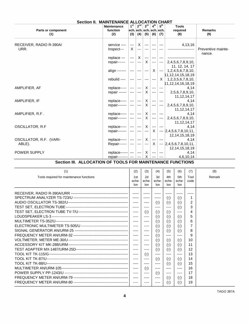
Section II. MAINTENANCE ALLOCATION CHARTMaintenance 1st 2nd 3rd 4th 5th Tools
Parts or component function ech. ech. ech. ech. ech. required Remarks(1) (2) (3) (4) (5) (6) (7) (8) (9)
RECEIVER, RADIO R-390A/ service ---- --- X --- --- --- 4,13,16URR. Inspect--- X --- --- --- --- --------------------- Preventive mainte-
nance.replace --- --- X --- --- --- ---------------------repair------ --- --- X --- --- 2,4,5,6,7,8,9,10,
11, 12, 14, 17align ------- --- --- --- X --- 1,2,4,5,6,7,8,10,
11,12,14,15,18,19rebuild ---- --- --- --- --- X 1,2,3,5,6,7,8,10,
11,12,14,16,18,19AMPLIFIER, AF replace----- --- --- X --- --- 4,14
repair ------ --- --- X --- --- 2,5,6,7,8,9,10,11,12,14,17
AMPLIFIER, IF replace----- --- --- X --- --- 4,14repair------- --- --- X --- --- 2,4,5,6,7,8,9,10,
11,12,14,17AMPLIFIER, R.F . replace----- --- --- X --- --- 4,14
repair------- --- --- X --- --- 2,4,5,6,7,8,9,10,11,12,14,17
OSCILLATOR, R.F replace----- --- --- X --- --- 4,14repair------- --- --- --- X --- 2,4,5,6,7,8,10,11,
12,14,15,18,19OSCILLATOR, R.F. (VARI- replace----- --- --- X --- --- 4,14
ABLE). Repair------ --- --- --- X --- 2,4,5,6,7,8,10,11,12,14,15,18,19
POWER SUPPLY replace------ --- --- X --- --- 4,14repair-------- --- --- X --- --- 4,6,10,14
Section III. ALLOCATION OF TOOLS FOR MAINTENANCE FUNCTIONS
(1) (2) (3) (4) (5) (6) (7) (8)
Tools required for maintenance functions 1st 2d 3d 4th 5th Tool Remarkeche- eche- eche- eche- eche- code
lon lon lon lon lon
RECEIVER, RADIO R-390A/URR --------------------------------------------- ----- ----- ----- ----- ----- -----SPECTRUM ANALYZER TS-723/U ------------------------------------------- ----- ----- ----- ( ) ( ) 1AUDIO OSCILLATOR TS-382/U----------------------------------------------- ---- ---- ( ) ( ) ( ) 2TEST SET, ELECTRON TUBE------------------------------------------------- ----- ---- ---- ---- ( ) 3TEST SET, ELECTRON TUBE TV-7/U--------------------------------------- ---- ( ) ( ) ( ) ---- 4LOUDSPEAKER LS-3 ------------------------------------------------------------ ---- ---- ( ) ( ) ( ) 5MULTIMETER TS-352/U--------------------------------------------------------- ---- ---- ( ) ( ) ( ) 6ELECTRONIC MULTIMETER TS-505/U ------------------------------------- ---- ---- ( ) ( ) ( ) 7SIGNAL GENERATOR AN/URM-25 ------------------------------------------ ---- ---- ( ) ( ) ( ) 8FREQUENCY METER AN/URM-32 ------------------------------------------- ---- ---- ( ) ---- ---- 9VOLTMETER, METER ME-30/U ----------------------------------------------- ---- ---- ( ) ( ) ( ) 10ACCESSORY KIT MK-288/URM----------------------------------------------- ---- ---- ( ) ( ) ( ) 11TEST ADAPTER MX-1487/URM-25D----------------------------------------- ---- ---- ( ) ( ) ( ) 12TOOL KIT TK-115/G-------------------------------------------------------------- ---- ( ) ---- ---- ---- 13TOOL KIT TK-87/U---------------------------------------------------------------- ---- ---- ( ) ( ) ( ) 14TOOL KIT TK-88/U---------------------------------------------------------------- ---- ---- ---- ( ) ( ) 15MULTIMETER AN/URM-105---------------------------------------------------- ---- ( ) ---- ---- ---- 16POWER SUPPLY PP-1243/U -------------------------------------------------- ---- ---- ( ) ---- ---- 17FREQUENCY METER AN/URM-79 ------------------------------------------- ---- ---- ---- ( ) ( ) 18FREQUENCY METER AN/URM-80 ------------------------------------------- ---- ---- ---- ( ) ( ) 19
TAGO 387A4
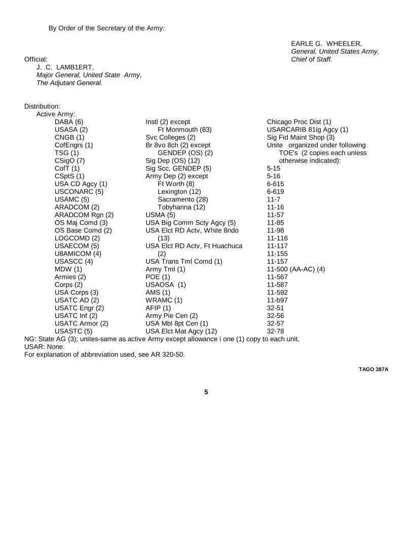
By Order of the Secretary of the Army:
EARLE G. WHEELER,General, United States Army,
Official: Chief of Staff.J. C. LAMB1ERT,Major General, United State Army,The Adjutant General.
Distribution:Active Army:
DABA (6) Instl (2) except Chicago Proc Dist (1)USASA (2) Ft Monmouth (83) USARCARIB 81ig Agcy (1)CNGB (1) Svc Colleges (2) Sig Fid Maint Shop (3)CofEngrs (1) Br 8vo 8ch (2) except Unite organized under followingTSG (1) GENDEP (OS) (2) TOE's (2 copies each unlessCSigO (7) Sig Dep (OS) (12) otherwise indicated):CofT (1) Sig Scc, GENDEP (5) 5-15CSptS (1) Army Dep (2) except 5-16USA CD Agcy (1) Ft Worth (8) 6-615USCONARC (5) Lexington (12) 6-619USAMC (5) Sacramento (28) 11-7ARADCOM (2) Tobyhanna (12) 11-16ARADCOM Rgn (2) USMA (5) 11-57OS Maj Comd (3) USA Big Comm Scty Agcy (5) 11-85OS Base Comd (2) USA Elct RD Actv, White 8ndo 11-98LOGCOMD (2) (13) 11-116USAECOM (5) USA Elct RD Actv, Ft Huachuca 11-117U8AMICOM (4) (2) 11-155USASCC (4) USA Trans Tml Comd (1) 11-157MDW (1) Army Tml (1) 11-500 (AA-AC) (4)Armies (2) POE (1) 11-567Corps (2) USAOSA (1) 11-587USA Corps (3) AMS (1) 11-592USATC AD (2) WRAMC (1) 11-b97USATC Engr (2) AFIP (1) 32-51USATC Inf (2) Army Pie Cen (2) 32-56USATC Armor (2) USA Mbl 8pt Cen (1) 32-57USASTC (5) USA Elct Mat Agcy (12) 32-78
NG: State AG (3); unites-same as active Army except allowance i one (1) copy to each unit.USAR: None.For explanation of abbreviation used, see AR 320-50.
TAGO 387A
5
*TM 11-5820-358-20/TO 31R1-2URR-442
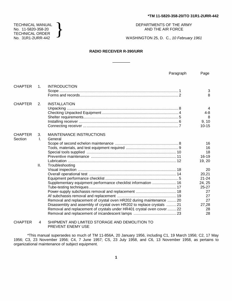
TECHNICAL MANUAL DEPARTMENTS OF THE ARMYNo. 11-5820-358-20 AND THE AIR FORCETECHNICAL ORDERNo. 31R1-2URR-442 WASHINGTON 25, D. C., 10 February 1961
RADIO RECEIVER R-390/URR
Paragraph Page
CHAPTER 1. INTRODUCTIONScope ............................................................................................................. 1 3Forms and records.......................................................................................... 2 8
CHAPTER 2. INSTALLATIONUnpacking ...................................................................................................... 8 4Checking Unpacked Equipment ...................................................................... 4 4-8Shelter requirements....................................................................................... 5 8Installing receiver ........................................................................................... 6 9, 10Connecting receiver ... .................................................................................... 7 10-15
CHAPTER 3. MAINTENANCE INSTRUCTIONSSection I. General
Scope of second echelon maintenance .......................................................... 8 16Tools, materials, and test equipment required ................................................ 9 16Special tools supplied .................................................................................. 10 18Preventive maintenance .............................................................................. 11 16-19Lubrication ................................................................................................... 12 19, 20
II. TroubleshootingVisual inspection .......................................................................................... 18 20Overall operational test ................................................................................ 14 20,21Equipment performance checklist ................................................................... 5 21-24Supplementary equipment performance checklist information ...................... 16 24, 25Tube-testing techniques ................................................................................ 17 25-27Power-supply subchassis removal and replacement ..................................... 18 27Af subchassis removal and replacement ...................................................... 19 27Removal and replacement of crystal oven HR202 during maintenance ........ 20 27Disassembly and assembly of crystal oven HR202 to replace crystals ......... 21 27,28Removal and replacement of crystals under HR401 crystal oven cover ........ 22 28Removal and replacement of incandescent lamps ....................................... 23 28
CHAPTER 4 SHIPMENT AND LIMITED STORAGE AND DEMOLITION TOPREVENT ENEMY USE
*This manual supersedes so much of TM 11-856A, 20 January 1956, including C1, 19 March 1956; C2, 17 May1956; C3, 23 November 1956; C4, 7 June 1957; CS, 23 July 1958, and C6, 13 November 1958, as pertains toorganizational maintenance of subject equipment.
1
}
Section I. Shipment and limited storageDisassembly.. ............................................................................................... 24Repacking for shipment or limited storage .................................................... 25
II. Demolition of material to present enemy useAuthority for demolition ................................................................................. 26Methods of destruction ................................................................................. 27
APPENDIX I. REFERENCES .................................................................................................II. MAINTENANCE ALLOCATION .......................................................................
2
CHAPTER 1
INTRODUCTION
1. ScopeThis annual covers the installation and second
echelon maintenance of Radio Receiver R490A/URR.The operating instructions for this equipment arecontained in TX 11-5820-858-10.
2. Forms and RecordsForward comments concerning this manual to
the Commanding Officer, U. S. Army Signal MaterielSupport Agency, ATTN: SIGMSPA2d, Fort Monmouth,N. J.
Note. For applicable form andrecords, see paragraph 2, TM 11-5820-358-10.
3

CHAPTER 2
INSTALLATION
3. Unpackinga. Packaging Data. When packed for shipment,
the components of the receiver are placed in a water-vaporproof container and packed in a wooden box. Anexploded view of the wooden box and its contents isshown in figure 1. The dimensions of the box areapproximately 241/4 inches high, 201/2 inches wide,and 14 3/4 inches deep. The packed box weighsapproximately .100 pounds, with a volume of 3.9 cubicfeet.
b. Removing Contents. Select a location wherethe equipment may be unpacked without exposure tothe weather, and which is convenient to the place ofinstallation.
CAUTION: Be careful whenuncrating, unpacking, and handlingthe equipment, because it is easilydamaged.
(1) Place the packing case conveniently nearthe installation location.
(2) Cut and fold back the metal straps.(3) Remove the nails with a nailpuller.(4) Remove the top and one side of the
wooden box.(5) Remove the desiccant bags, the
cardboard tray, and the plywood board.(6) Take out the outer cardboard carton that
contains the receiver.(7) Open the carton and withdraw the inner
carton that is enclosed in the moisture-vaporproof barrier.
(8) Slit open the seams of the moisturevaporproof barrier and open the innercardboard carton.
(9) Remove any spacers or padding from theinner cardboard carton.
(10) Withdraw the receiver from the innercarton and place it on a workbench nearits final location.
(11) Remove the technical manuals and therunning spares.
4. Checking Unpacked Equipmenta. Check the contents of the cartons against the
master packing slip.b. Check the receiver front panel for damage to
the knobs, the glass meter windows, and the frequency-indicator dial.
c. Operate the control knobs; examine them forlooseness.
d. Turn the MEGACYCLE CHANGE and theKILOCYCLE CHANGE controls throughout their range.Rough operation or binding indicates a damaged tuningsystem.
e. Remove the top and bottom dust covers byremoving the 16 screws (TM 11-5820-358-10) andlockwashers that secure the covers to the main frame.
f. Inspect the subchassis on the upper and lowerdecks of the receiver for' loose connectors, loose tubeshields, and broken tubes as follows:
(1) See that all connectors are seated firmly.(2) If the receiver is to be used in a fixed
installation, remove the shields from alltubes (fig. 2 and 3) except V201 throughV206, V505, and V701.
(3) Unless extremely dusty conditions areexpected, do not replace the dust covers.
(4) Do not replace the dust covers if thereceiver is to be installed in Cabinet CY-979/URR or Cabinet CY-917/ URR.
g. Remove the fuse from the fuseholder on therear panel (TM 11-5820-358-10) marked AC 3 AMP.Check the position of the OVENS switch on the rearpanel. Refer to the chart below for the proper fuserating.
CAUTION: To avoid serious damageto the
4

Figure 1. Packaging.
5
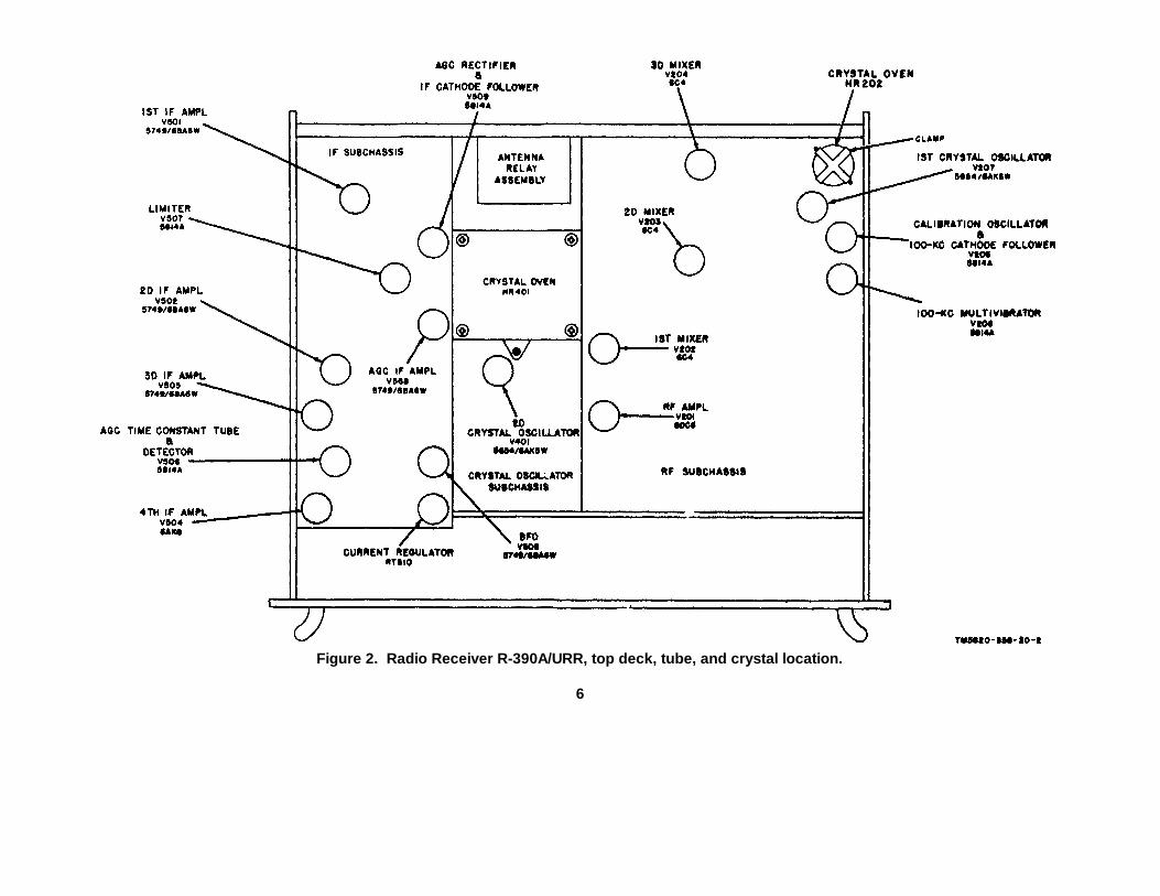
Figure 2. Radio Receiver R-390A/URR, top deck, tube, and crystal location.
6
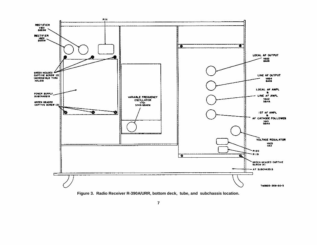
Figure 3. Radio Receiver R-390A/URR, bottom deck, tube, and subchassis location.
7
receiver, do not use any fuse other than the valuespecified.
Ac source OVENS switch Fuse ratingvoltage position in amperes
115-volt ON 3115-volt, OFF 2230-volt ON 1 1/2280-volt OFF 1
Note. Receivers bearing order No.14-Phila-56, serial numbers 2688 andabove, and order No. 14385-Phila-58have a 1/4-ampere and a 1/8-ImpereB+ fuse on the rear panel forprotection against short circuits Inthe B+ circuits.
h. Inspect for bent or broken connector andterminals on the rear panel. See that the special toolsare in place in their holders, and that the spare fusesare-of proper rating and clipped firmly to the rear panel(TM 11-5820-58-10).
i. Check the contents of the running spares boxfor damaged parts.5. Shelter RequirementsThe shelter housing should be sufficiently weathertightto protect the equipment.. The shelter should allowenough room for free air circulation.
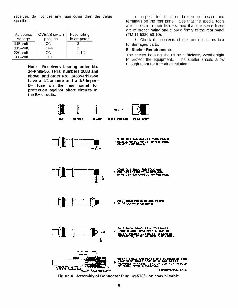
Figure 4. Assembly of Connector Plug Ug-573/U on coaxial cable.
8
6. Installing Receivera. Antenna. The receiver is frequently used with a
rhombic, doublet, or double-doublet antenna.
(1) For information concerning rhombic anddoublet antennas, refer to TM 11-666.
(2) For double-doublet information, refer toTM 11-2629.
b. Assembling Connector Plug UG-573/U. Figure4 gives complete instructions for assembling ConnectorPlug UG-573/U or Connector Plug P-259.
c. Receiver. The receiver is shipped with all tubes,crystals, and fuses in place. When the receiver is to beused as part of a system, refer also to the systemtechnical manual for instructions.
(1) Fixed, tabletop installation. The receiveris housed in Cabinet CY-917/ URR or in asimilar well-ventilated case for fixedoperation.
(a) Place the receiver on any sturdytable or bench.
(b) Use the receiver without the top andbottom dust covers and without thetube shields (para 4e).
(2) Fixed, rack installation. To install thereceiver in a standard rack, proceed asfollows:
(a) Remove the top and bottom dustcovers.
(b) Remove the tube shields asdirected in (b) above.
(c) Remove one of the blank panelsfrom the rack.
(d) Install the angle brackets that comewith the rack for received support.
(e) Slide the receiver into place.(f) Insert the bolts, which were
removed from the blank panel,through the elongated holes locatedalong the vertical edges of
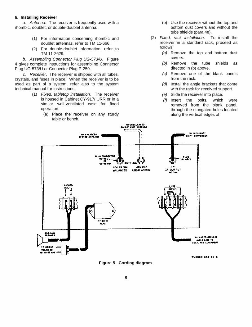
Figure 5. Cording diagram.
9
the receiver front panel. (TM115820-358-10).
(3) Mobile, tabletop installation. To install thereceiver for mobile operation whenhoused in Cabinet CY979/URR, proceedas follows:
(a) Bolt the cabinet securely to a tableor shelf that is fastened rigidly to thevehicle.
(b) Allow space for ventilation, foraccess to the connections on therear panel, and for withdrawal of thereceiver from the cabinet forservicing.
(c) Remove the top and bottom dustcovers (para 4 e).
(d) Remove the blank panel from thecabinet and install the receiver.
(e) Secure the front panel to thecabinet, with the bolts removedfrom the blank panel.
(4) Mobile, cabinet, or rack installation. Toinstall the receiver in Electrical Equipment Cabinet CY-1216/U, securely bolt the receiver cabinet or rack to thebody of the vehicle.
(5) Ventilation. In all installations, provide asmuch ventilation as possible.
(a) Do not use the receiver with thedust covers in place unlessextremely dusty or sandy conditionsexist.
(b) For tabletop cabinets, remove thedust covers before the receiver isinstalled.
(c) In fixed installations, operate the
receiver with the specified tubeshields removed (para 4f).
(d) Allow as much space as possible atthe back of the cabinet or rack forair circulation.
(e) When more than one receiver ishoused in a cabinet, always use a 13/4-inch or larger blank stripbetween the receivers.
(6) Support. For mobile installations, providesupport for the lower rear of the receiver.This support is provided in the cabinetslisted in (3) and (4) above. For othercabinets, use the mounting holes that areprovided at the rear of the receiver.Dowel pins may be inserted to hold thereceiver securely. The drawing of therear panel of the receiver (TM 11-5820-358-10) shows the locations anddimensions of the dowel pin gussets(lower corners).
7. Connecting Receiver (fig. 5, 4, and 7)The receiver will operate from either 115 or 230
volts ac. The power transformer can be damaged if 230volts is applied to it when it is connected to operate on115 volts. To check to see that the TB801 is connectedfor the correct alternating current (ac) voltage, connectthe receiver to a 115-volt ac line, turn the receiver on,and proceed as follows:
a. If the pilot lamps light at full brilliance, thereceiver is connected for 115-volt operation.
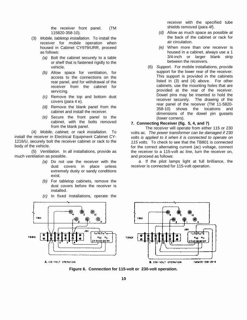
Figure 6. Connection for 115-volt or 230-volt operation.
10
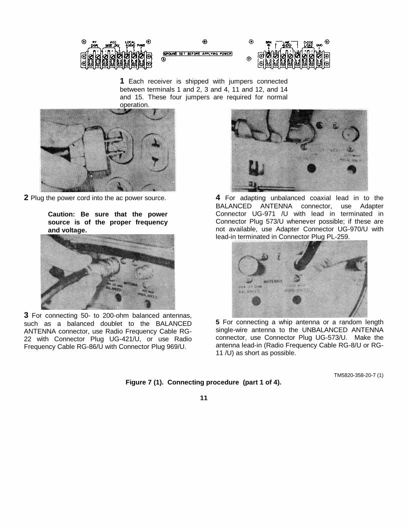
1 Each receiver is shipped with jumpers connectedbetween terminals 1 and 2, 3 and 4, 11 and 12, and 14and 15. These four jumpers are required for normaloperation.
2 Plug the power cord into the ac power source.
Caution: Be sure that the powersource is of the proper frequencyand voltage.
3 For connecting 50- to 200-ohm balanced antennas,such as a balanced doublet to the BALANCEDANTENNA connector, use Radio Frequency Cable RG-22 with Connector Plug UG-421/U, or use RadioFrequency Cable RG-86/U with Connector Plug 969/U.
4 For adapting unbalanced coaxial lead in to theBALANCED ANTENNA connector, use AdapterConnector UG-971 /U with lead in terminated inConnector Plug 573/U whenever possible; if these arenot available, use Adapter Connector UG-970/U withlead-in terminated in Connector Plug PL-259.
5 For connecting a whip antenna or a random lengthsingle-wire antenna to the UNBALANCED ANTENNAconnector, use Connector Plug UG-573/U. Make theantenna lead-in (Radio Frequency Cable RG-8/U or RG-11 /U) as short as possible.
TM5820-358-20-7 (1)Figure 7 (1). Connecting procedure (part 1 of 4).
11

6 Perform step 7, 8, or 9 below, depending on the typeof listening device used.
7 Plug the headset into the PHONES jack.
8 Connect the headset terminals to PHNS terminal 8and terminal 7 (ground).
9 Connect the loudspeaker terminals to LOCAL AUDIOterminals 6 and 7.
10 For balanced line operation, connect the balancedline to LINE AUDIO terminals 10 and 13. If a balancingbridge is to be used for long-distance applications,perform steps 11 and 12 below.
11 Remove the jumper from terminals 11 and 12.
12 Connect the balancing bridge between terminals11 and 12.
TM5820-358-20-7 (2)Figure 7 (2). Connecting procedure (part 2 of 4).
12
b. If the pilot lamps light at half brilliance, thereceiver is connected for 230-volt operation.
c. If the pilot lamps light at full brilliance and thereceiver is to be used on 230 volts, disconnect thereceiver and remove the power supply subchassis fromit (para 18). Connect T801 for 230-volt operation (fig.6).
WARNING: The voltages used inthis receiver are high enough toendanger human life. To preventshock hazard to personnel touchingoutside metal parts of the receiver,connect GND terminal 16 on the rearpanel to the same ground as that ofthe power source. Do not depend onthe front panel screws or the antennatransmission line to ground thechassis.
13
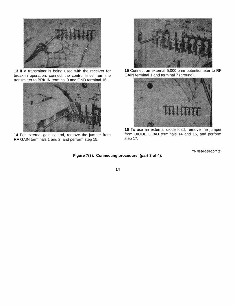
13 If a transmitter is being used with the receiver forbreak-in operation, connect the control lines from thetransmitter to BRK IN terminal 9 and GND terminal 16.
14 For external gain control, remove the jumper fromRF GAIN terminals 1 and 2, and perform step 15.
15 Connect an external 5,000-ohm potentiometer to RFGAIN terminal 1 and terminal 7 (ground).
16 To use an external diode load, remove the jumperfrom DIODE LOAD terminals 14 and 15, and performstep 17.
TM 5820-358-20-7 (3)Figure 7(3). Connecting procedure (part 3 of 4).
14
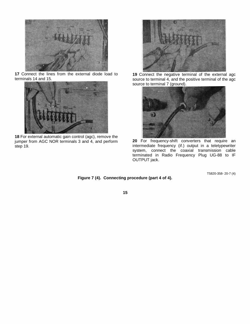
17 Connect the lines from the external diode load toterminals 14 and 15.
18 For external automatic gain control (agc), remove thejumper from AGC NOR terminals 3 and 4, and performstep 19.
19 Connect the negative terminal of the external agcsource to terminal 4, and the positive terminal of the agcsource to terminal 7 (ground).
20 For frequency-shift converters that require anintermediate frequency (if.) output in a teletypewritersystem, connect the coaxial transmission cableterminated in Radio Frequency Plug UG-88 to IFOUTPUT jack.
T5820-358- 20-7 (4)Figure 7 (4). Connecting procedure (part 4 of 4).
15

CHAPTER 3
MAINTENANCE INSTRUCTIONS
Section I. GENERAL
8. Scope of Second Echelon MaintenanceSecond echelon maintenance consists of the following:
a. Replacement of defective fuses (TM 11-5820-358-10).
b. Preventive maintenance (para 11).c. Lubrication (para 12).d. Visual inspection (para 13).e. Overall operational test (para 14).f. Troubleshooting (sect II).g. Tube testing (para 17).h. Replacement of power supply and audio
frequency (af) subchassis (para 18 and 19).
i. Replacement of crystals and incandescentlamps (para 20-23).9. Tools, Materials, and Test Equipment RequiredThe materials, tools, and test equipment required forsecond echelon maintenance are listed below.
a. Tools.Tool Equipment, TE-41.
b. Materials.Cheesecloth, bleached, lint-free.Cleaning Compound (Federal stock No.7930-395-9542).
c. Test Equipment.
Nomenclature Common name Technical manualTest Sets Electron Tube TV-7/U, TV-7A/U, TV-7B/U, Tube tester TM 11-6625-274-12
and TV-D/U, or equal
Multimeter AN/URM-105 .......................................... Multimeter RM 17-6625-203-12
10. Special Tools Supplied (TM 11-5820-358-10)a. Phillips Screwdriver. The Phillips screwdriver is
used to remove the screws that fasten the dust covers,the front panel, the removable subchassis, and theterminal boards.
b. Bristo (Fluted) Socket Wrench. The No. 8fluted socket wrench is used for removing the frontpanel bar knobs and the MEGACYCLE CHANGE andKILOCYCLE CHANGE knobs.
11. Preventive Maintenancea. DA Form 11-238. DA Form 11-238 (fig. 8) is a
preventive maintenance checklist to be used by thesecond echelon repairman. Items not applicable to theequipment or to second echelon maintenance are ruledout in the figure. Check items 13 through 27 at leastonce per month. References in the ITEM block in thefigure are to paragraphs that contain additionalinformation pertinent to the particular item. Instructionsfor the use of the form appear on the form.
b. Items. The information in the chart below issupplementary to DA Form 11-238.
16
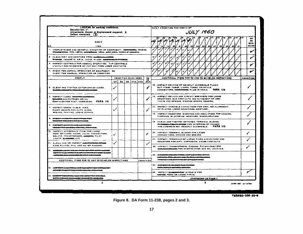
Figure 8. DA Form 11-238, pages 2 and 3.
17

Figure 9. DA Form 11-238, pages 1 and 4.
18

pass the tests, alignment or circuit repair is usuallyrequired at a higher maintenance level. Before turningin the receiver, refer to paragraph 16f (5) and (6).
Control PositionRF GAIN 10FUNCTION switch CALBFO switch ONBFO PITCH control +2LINE GAIN control 10LOCAL GAIN control 6BANDWIDTH KC switch 4AUDIO RESPONSE switch WIDEAGC switch MEDLIMITER control OFFLINE METER switch 0
b. Disconnect the antenna. Tune the KILOCYCLECHANGE control to any 100-kilocycle (kc) point for amaximum indication of the CARRIER LEVEL meter.
c. Starting at 02, turn the MEGACYCLE CHANGEcontrol to each band. Adjust the ANT TRIM andKILOCYCLE CHANGE controls for maximum indicationof the CARRIER LEVEL meter for each band. Listen tothe signal produced by the calibration oscillator. Thesignal should be approximately at the same level for allbands. The minimum indication of the LINE LEVELmeter should be at the VU mark for all bands. This testwill indicate which bands are not operating properly.Either alignment or circuit repair of these bands isusually required to return the bands
to normal sensitivity. This work will be done at a highermaintenance level.
d. Turn the BFO switch to OFF and listen for ahum in the headset or loudspeaker. A slight hum isnormal, but excessive hum indicates the need for repairat a higher maintenance level.
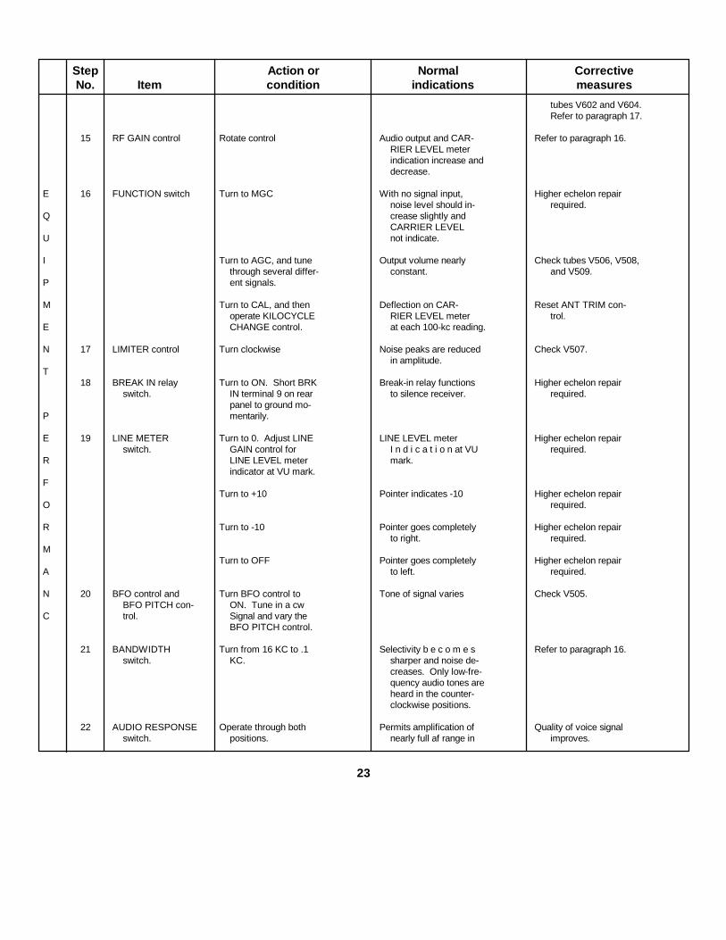
15. Equipment Performance Checklista. General. The equipment performance checklist
(e below) will help the repairman to locate faults in thereceiver. The list gives the items to be checked, theconditions under which the items are checked, thenormal indications of correct operation, and thecorrective measures to be taken. Follow the items innumerical sequence.
b. Action or Condition. For some items, theinformation given in the Action or condition columnconsists of the various switch and control settings withwhich the items are to be checked. For other items, itrepresents an action that must be taken to check thenormal indication.
c. Normal Indications. The normal indicationslisted include the visible and audible signs that therepairman should observe when the items are checked.
d. Corrective Measures. The corrective measureslisted are those that the second echelon repairman canmake without turning the equipment in for higherechelon repairs. If the recommended correctivemeasures do not remove the fault, higher echelon repairis necessary.
e. Equipment Performance Checklist.
Step Action or Normal CorrectiveNo. Item condition indications measures
P 1 Antenna Lead-in wire connected.RE 2 Loudspeaker or head- Loudspeaker connectedP set. to LOCAL AUDIOA terminals 6 and 7, orR headset lugged into PHONES jack.AT 3 600-ohm line Connected to terminalsO 10 and 1. If 600-ohmR line is not available,Y connect headset to
21

Step Action or Normal CorrectiveNo. Item condition indications measures
terminals for testpurpose
PR 4 Power cord Connected to ac powerE source.PA 5 AUDIO RESPONSE Set at WIDE.R switch.AT 6 BANDWIDTH Set at 8 KC.O switch.RY 7 RF GAIN Set at 10.
8 LOCAL GAIN Set at 6.control.
E 9 FUNCTION switch- Turn to AGC Dial lamps light Check power cord, Checkdial lamps and AC 3
Q AMP fuse. Refer toTM 11-5820-358-10.
URushing noise or signal Test tubes. Check con-
I heard in speaker or nectors between sub-headset chassis. Refer to para-
P graphs 14, 16, and 17.
M 10 MEGACYCLE Set at each band in Normal signal output Rotate control severalCHANGE turn. on each band. times to clean switch
E control contacts.
N Refer to paragraphs 14and 16.
T11 KILOCYCLE Tune across any band Signals received. CAR- Refer to paragraphs 14,
CHANGE RIER LEVEL meter 16 and 17.P control indicates strength of
received signals.E
12 ANT TRIM Rotate control Obtain peak indication Refer to paragraphs 14,R on CARRIER LEV- 16, and 17.
EL meter for eachF band.
O 13 LOCAL GAIN Rotate control in either Volume at loudspeaker Refer to paragraphs 14,control. direction. or headset increases 16 and 17.
R and decreases.
M 14 LINE GAIN control Rotate control Output level to 600-ohm If headset level variesline or headset and and pointer of meter
A LINE LEVEL meter is sticking, tap meterincreases and de- lightly.
N creases.
C If local output is satis-factory but line out-
E put is weak, check
22
Step Action or Normal CorrectiveNo. Item condition indications measures
tubes V602 and V604.Refer to paragraph 17.
15 RF GAIN control Rotate control Audio output and CAR- Refer to paragraph 16.RIER LEVEL meterindication increase anddecrease.
E 16 FUNCTION switch Turn to MGC With no signal input, Higher echelon repairnoise level should in- required.
Q crease slightly andCARRIER LEVEL
U not indicate.
I Turn to AGC, and tune Output volume nearly Check tubes V506, V508,through several differ- constant. and V509.
P ent signals.
M Turn to CAL, and then Deflection on CAR- Reset ANT TRIM con-operate KILOCYCLE RIER LEVEL meter trol.
E CHANGE control. at each 100-kc reading.
N 17 LIMITER control Turn clockwise Noise peaks are reduced Check V507.in amplitude.
T18 BREAK IN relay Turn to ON. Short BRK Break-in relay functions Higher echelon repair
switch. IN terminal 9 on rear to silence receiver. required.panel to ground mo-
P mentarily.
E 19 LINE METER Turn to 0. Adjust LINE LINE LEVEL meter Higher echelon repairswitch. GAIN control for I n d i c a t i o n at VU required.
R LINE LEVEL meter mark.indicator at VU mark.
FTurn to +10 Pointer indicates -10 Higher echelon repair
O required.
R Turn to -10 Pointer goes completely Higher echelon repairto right. required.
MTurn to OFF Pointer goes completely Higher echelon repair
A to left. required.
N 20 BFO control and Turn BFO control to Tone of signal varies Check V505.BFO PITCH con- ON. Tune in a cw
C trol. Signal and vary theBFO PITCH control.
21 BANDWIDTH Turn from 16 KC to .1 Selectivity b e c o m e s Refer to paragraph 16.switch. KC. sharper and noise de-
creases. Only low-fre-quency audio tones areheard in the counter-clockwise positions.
22 AUDIO RESPONSE Operate through both Permits amplification of Quality of voice signalswitch. positions. nearly full af range in improves.
23
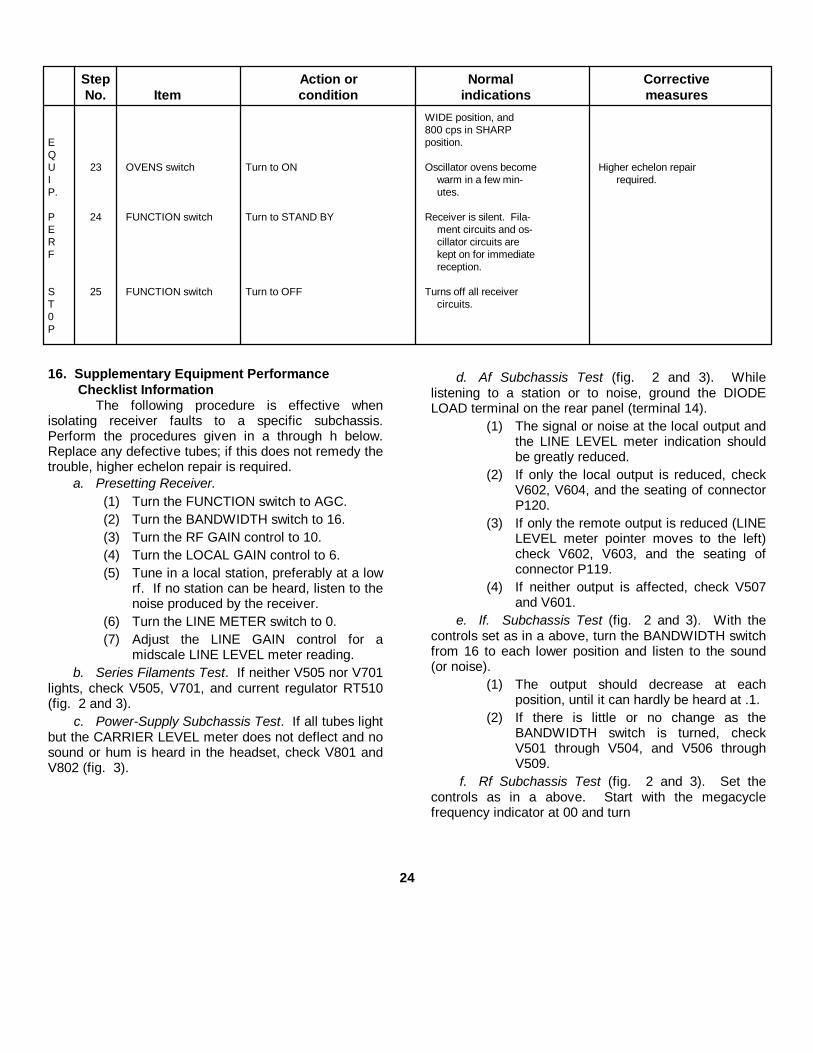
Step Action or Normal CorrectiveNo. Item condition indications measures
WIDE position, and800 cps in SHARP
E position.QU 23 OVENS switch Turn to ON Oscillator ovens become Higher echelon repairI warm in a few min- required.P. utes.
P 24 FUNCTION switch Turn to STAND BY Receiver is silent. Fila-E ment circuits and os-R cillator circuits areF kept on for immediate
reception.
S 25 FUNCTION switch Turn to OFF Turns off all receiverT circuits.0P
16. Supplementary Equipment Performance Checklist Information
The following procedure is effective whenisolating receiver faults to a specific subchassis.Perform the procedures given in a through h below.Replace any defective tubes; if this does not remedy thetrouble, higher echelon repair is required.
a. Presetting Receiver.(1) Turn the FUNCTION switch to AGC.(2) Turn the BANDWIDTH switch to 16.(3) Turn the RF GAIN control to 10.(4) Turn the LOCAL GAIN control to 6.(5) Tune in a local station, preferably at a low
rf. If no station can be heard, listen to thenoise produced by the receiver.
(6) Turn the LINE METER switch to 0.(7) Adjust the LINE GAIN control for a
midscale LINE LEVEL meter reading.b. Series Filaments Test. If neither V505 nor V701
lights, check V505, V701, and current regulator RT510(fig. 2 and 3).
c. Power-Supply Subchassis Test. If all tubes lightbut the CARRIER LEVEL meter does not deflect and nosound or hum is heard in the headset, check V801 andV802 (fig. 3).
d. Af Subchassis Test (fig. 2 and 3). Whilelistening to a station or to noise, ground the DIODELOAD terminal on the rear panel (terminal 14).
(1) The signal or noise at the local output andthe LINE LEVEL meter indication shouldbe greatly reduced.
(2) If only the local output is reduced, checkV602, V604, and the seating of connectorP120.
(3) If only the remote output is reduced (LINELEVEL meter pointer moves to the left)check V602, V603, and the seating ofconnector P119.
(4) If neither output is affected, check V507and V601.
e. If. Subchassis Test (fig. 2 and 3). With thecontrols set as in a above, turn the BANDWIDTH switchfrom 16 to each lower position and listen to the sound(or noise).
(1) The output should decrease at eachposition, until it can hardly be heard at .1.
(2) If there is little or no change as theBANDWIDTH switch is turned, checkV501 through V504, and V506 throughV509.
f. Rf Subchassis Test (fig. 2 and 3). Set thecontrols as in a above. Start with the megacyclefrequency indicator at 00 and turn
24

the MEGACYCLE CHANGE control through its range tothe highest frequency and listen to the noise in theheadset.
(1) Across the tuning range, some adjustmentof the ANT TRIM control is necessary toproduce maximum noise.
(2) The noise at each detent position shouldbe almost constant.
(3) There should be a pronounced increase innoise as the control is seated in eachdetent.
(4) If the rf tuner does not pass this test,check V201 through V204, V207 andV701.
Note. When V701 is replaced, thesubchassis must be realigned athigher echelon.
(5) If all the bands except 00 through 08operate, change crystal Y201 (para 20and 21).
(6) Each crystal in crystal oven HR401 fig. 2and 12) operates a megacycle band or acombination or 1-megacycle bands. Todetermine which crystal is defective,proceed as follows:
(a) Turn the MEGACYCLE CHANGEcontrol to each band to determinewhich bands are inoperative.
(b) Record the numbers of thedefective bands.
(c) Match the combination of defectivebands with the combinations listedin the chart below.
(d) Replace the defective crystal (para22).
Megacycle band affected Crystal in use00, 17 Y40101, 18 Y40202, 08, 19, 30 Y40303, 20 Y40404, 09, 21 Y40505, 22 Y40606, 10, 23 Y40707, 15, 24 Y40811, 25 Y40912, 27 Y41013, 29 Y41114, 81 Y41216 Y41326 Y41428 Y415
g. Calibration Oscillator Test. To test thecalibration oscillator, proceed as follows:
(1) Turn the FUNCTION switch to CAL.(2) Turn the MEGACYCLE CHANGE control
to band 00.(3) Tune the KILOCYCLE CHANGE control
through its entire range.(4) Listen for a beat note at every 100kc point
as the KILOCYCLE CHANGE control is tuned.(5) If the calibrator fails to operate, make the
following tests in the order indicated:(a) Check V205 and V206 (fig. 2).(b) Replace Y203 (para 21).(c) If the fault cannot be remedied by
this procedure, higher echelonrepair is required.
h. Antenna Circuit Test. Rotate the ANT TRIMcontrol. The CARRIER LEVEL meter should peak atone particular point.
(1) Disconnect the antenna and ground theANTENNA UNBALANCED connector. Aclick should be heard and the noiseshould drop sharply.
(2) Ground both contacts of the ANTENNABALANCED connector. A click should beheard and the noise should drop sharply.
(3) If the receiver does not pass this test,check the connectors on the antennarelay box.
17. Tube-Testing Techniquesa. Inspect all interior cable connectors for proper
seating before removing the tubes.b. Isolate the trouble to a specific subchassis of
the receiver (para 16).c. Use Test Set Electron Tube TV-7/U or
equivalent, and proceed as follows:(1) Remove and test one tube at a time.(2) Substitute new tubes for only those tubes
that are defective.(3) Immediately discard tubes that are
shorted or contain heater-to-cathodeleakage.
d. If a tube tester is not available, use the tube-substitution method.
(1) Substitute a new tube for an original one.If no change is apparent, in the operation of thereceiver, replace the new tube with the original. Check
25
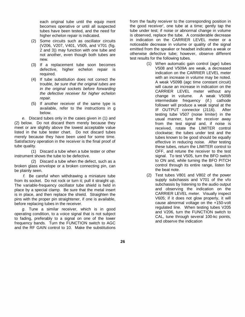
each original tube until the equip mentbecomes operative or until all suspectedtubes have been tested, and the need forhigher echelon repair is indicated.
(2) Some circuits such as oscillator circuits(V206, V207, V401, V505, and V701 (fig.2 and 3)) may function with one tube andnot another, even though both tubes arenew.
(3) If a replacement tube soon becomesdefective, higher echelon repair isrequired.
(4) If tube substitution does not correct thetrouble, be sure that the original tubes arein the original sockets before forwardingthe defective receiver for higher echelonrepair.
(5) If another receiver of the same type isavailable, refer to the instructions in gbelow.
e. Discard tubes only in the cases given in (1) and(2) below. Do not discard them merely because theymeet or are slightly above the lowest acceptable valuelisted in the tube tester chart. Do not discard tubesmerely because they have been used for some time.Satisfactory operation in the receiver is the final proof oftube quality.
(1) Discard a tube when a tube tester or otherinstrument shows the tube to be defective.
(2) Discard a tube when the defect, such as abroken glass envelope or a broken connecting pin, canbe plainly seen.
f. Be careful when withdrawing a miniature tubefrom its socket. Do not rock or turn it; pull it straight up.The variable-frequency oscillator tube shield is held inplace by a special clamp. Be sure that the metal insertis in place, and then replace the shield. Straighten thepins with the proper pin straightener, if one is available,before replacing tubes in the receiver.
g. Tune a similar receiver, which is in goodoperating condition, to a voice signal that is not subjectto fading, preferably to a signal on one of the lowerfrequency bands. Turn the FUNCTION switch to AGCand the RF GAIN control to 10. Make the substitutions
from the faulty receiver to the corresponding position inthe good receiver', one tube at a time; gently tap thetube under test; if noise or abnormal change in volumeis observed, replace the tube. A considerable decreasein indication on the CARRIER LEVEL meter or anoticeable decrease in volume or quality of the signalemitted from the speaker or headset indicates a weak orotherwise defective tube; however, observe differenttest results for the following tubes.
(1) When automatic gain control (age) tubesV508 and V509A are weak, a decreasedindication on the CARRIER LEVEL meterwith an increase in volume may be noted.A weak V509B (agc time constant circuit)will cause an increase in indication on theCARRIER LEVEL meter without anychange in volume. A weak V509Bintermediate frequency (if.) cathodefollower will produce a weak signal at theIF OUTPUT connector (J116). Aftertesting tube V507 (noise limiter) in theusual manner, tune the receiver awayfrom the test signal and, if noise isreceived, rotate the LIMITER controlclockwise; the tubes under test and thetubes known to be good should be equallyeffective in reducing noise. After testingthese tubes, return the LIMITER control toOFF, and retune the receiver to the testsignal. To test V505, turn the BFO switchto ON and, while turning the BFO PITCHcontrol through its entire range, listen forthe beat note.
(2) Test tubes V801 and V802 of the powersupply subchassis and V701 of the vfosubchassis by listening to the audio outputand observing the indication on theCARRIER LEVEL meter. Visually inspectV605; if it does not glow properly, it willcause abnormal voltage on the +150-voltregulated line. When testing tubes V205and V206, turn the FUNCTION switch toCAL, tune through several 100-kc points,and observe the indication
26
on the CARRIER LEVEL meter.(3) Test the tubes in the af circuits by
listening to the quality of the output signalof the af channels. When testing tubesV602A and V603 (local af amplifier), listento the output of the local audio channel.When testing tubes V602B (line afamplifier) and V604, listen to the outputsignal from the balanced-line circuit andobserve the indication on the LINE LEVELmeter. Tube V601 is common to both thelocal and the line af channels. Generally,small changes in LINE LEVEL meterindication may be expected because ofcertain differences among tubes.
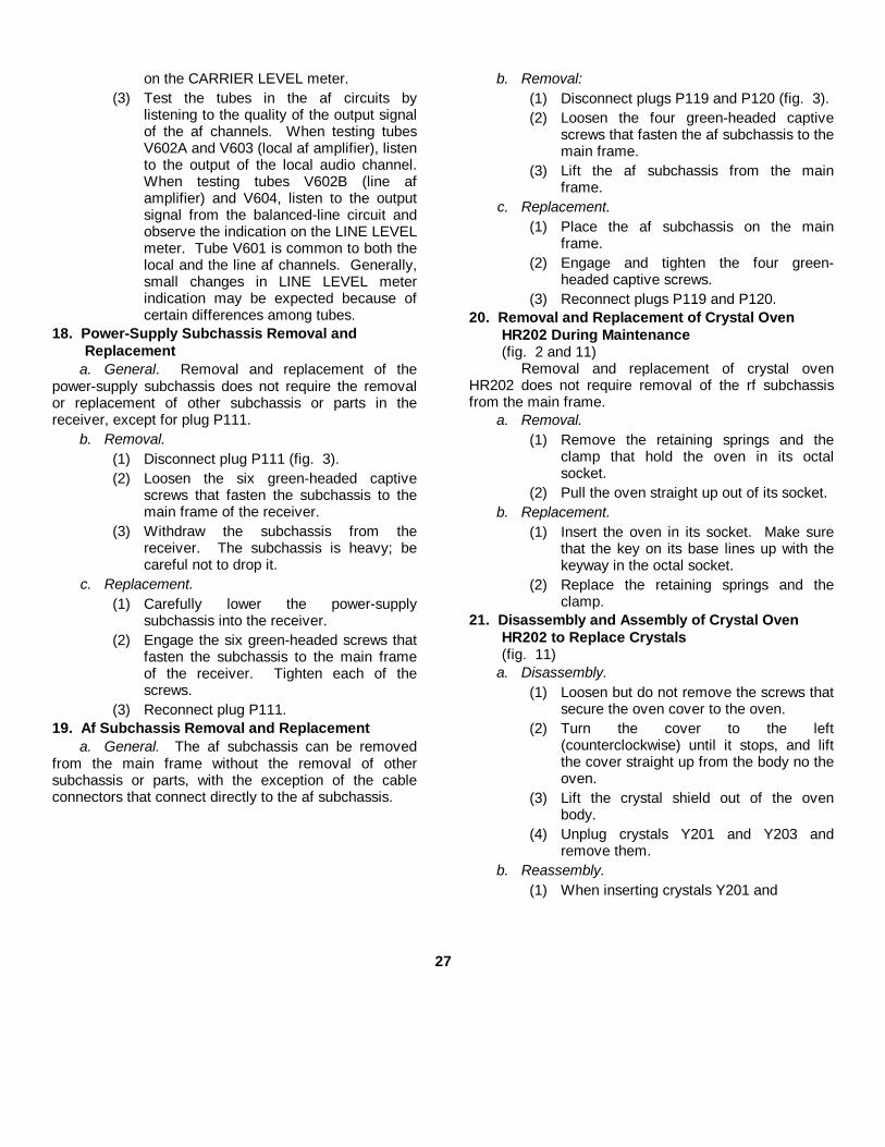
18. Power-Supply Subchassis Removal and Replacement
a. General. Removal and replacement of thepower-supply subchassis does not require the removalor replacement of other subchassis or parts in thereceiver, except for plug P111.
b. Removal.(1) Disconnect plug P111 (fig. 3).(2) Loosen the six green-headed captive
screws that fasten the subchassis to themain frame of the receiver.
(3) Withdraw the subchassis from thereceiver. The subchassis is heavy; becareful not to drop it.
c. Replacement.(1) Carefully lower the power-supply
subchassis into the receiver.(2) Engage the six green-headed screws that
fasten the subchassis to the main frameof the receiver. Tighten each of thescrews.
(3) Reconnect plug P111.19. Af Subchassis Removal and Replacement
a. General. The af subchassis can be removedfrom the main frame without the removal of othersubchassis or parts, with the exception of the cableconnectors that connect directly to the af subchassis.
b. Removal:(1) Disconnect plugs P119 and P120 (fig. 3).(2) Loosen the four green-headed captive
screws that fasten the af subchassis to themain frame.
(3) Lift the af subchassis from the mainframe.
c. Replacement.(1) Place the af subchassis on the main
frame.(2) Engage and tighten the four green-
headed captive screws.(3) Reconnect plugs P119 and P120.
20. Removal and Replacement of Crystal Oven HR202 During Maintenance(fig. 2 and 11)
Removal and replacement of crystal ovenHR202 does not require removal of the rf subchassisfrom the main frame.
a. Removal.(1) Remove the retaining springs and the
clamp that hold the oven in its octalsocket.
(2) Pull the oven straight up out of its socket.b. Replacement.
(1) Insert the oven in its socket. Make surethat the key on its base lines up with thekeyway in the octal socket.
(2) Replace the retaining springs and theclamp.
21. Disassembly and Assembly of Crystal Oven HR202 to Replace Crystals(fig. 11)
a. Disassembly.(1) Loosen but do not remove the screws that
secure the oven cover to the oven.(2) Turn the cover to the left
(counterclockwise) until it stops, and liftthe cover straight up from the body no theoven.
(3) Lift the crystal shield out of the ovenbody.
(4) Unplug crystals Y201 and Y203 andremove them.
b. Reassembly.(1) When inserting crystals Y201 and
27

Figure 11. Location of crystal Y201 and Y202.
Y203, be sure to plug them in at theproper locations with respect to the key onthe base (fig. 11).
(2) Gently push the crystal shield back intoplace.
(3) Line up the slots at the base of the coverwith the screws on the base of the crystaloven.
(4) Push the cover down and turn it to theright (clockwise) until it stops.
(5) Tighten the securing screws on the base.
22. Removal and Replacement of Crystals Under HR401 Crystal Oven Cover(fig. 2 and 12)
a. Removal.(1) Remove the Phillips screw and the
lockwasher from the top of the subchassisand the two similar screws andlockwashers at the rear end of thesubchassis.
Note. Do not loosen the fourPhillips screws on top of the ovencover.
Figure 12. Location of crystals Y401 through Y415.
(2) Lift the cover straight up from the oven.(3) The 15 plug-in crystals, Y401 through
Y415, are now accessible for replacement(para 16f (6) ).
(4) Pull the defective crystal straight up out ofthe crystal socket.
b. Replacement.(1) Replace the defective crystal.(2) Replace the oven cover. Be sure that the
two plugs at the bottom rear of the ovencover line up with their jacks on thesubchassis.
(3) Replace the three Phillips screws and thelockwashers.
23. Removal and Replacement of Incandescent Lamps (TM 11-5820-358-10)
a. Removal.(1) Remove the four Phillips screws from the
corners of the frequency indicator window.(2) Move the frequency-indicator window a
few inches away from the front panel. Itsconnecting wires will hold it in position.
(3) Remove the defective incandescentlamps.
b. Replacement.(1) Insert the new incandescent lamps.(2) Place the frequency-indicator window in
position; line up the four screw holes.(3) Replace and tighten the four Phillips
screws.
28

CHAPTER 4
SHIPMENT AND LIMITED STORAGE AND DEMOLITION
TO PREVENT ENEMY USE
Section I. SHIPMENT AND LIMITED STORAGE
24. DisassemblyThe following instructions are recommended as
a guide for preparing the receiver for transportation andstorage.
a. Disconnect the antenna lead-in cable.b. Remove all connections to the terminal strips on
the rear panel of the receiver.c. Unplug the headphone cord from the PHONES
jack on the front panel.d. Disconnect the power cable from the ac outlet
and wind the cable around the clips provided for it onthe rear panel of the receiver.
25. Repacking for Shipment or Limited StorageThe exact procedure for repacking depends on
the material available and the conditions under whichthe receiver is to be shipped or stored. Follow theprocedures outlined in a through c below wheneverpossible, as well as the information concerning theoriginal packaging (para 3 and fig. 1).
a. Materials Requirement.Material Quantity
Waterproof-barrier material 22 sq ftFiberboard, corrugated, single-faced 40 sq ftTape, gummed, paper 10 ftTape, water-resistant, pressure-sensitive, 16 ft
3-inchSteel strapping, 5/8-inch by 0.020-inch 13 ftWooden shipping box, 22 1/4 x 20 1/2 x 14 3/4 1
b. Packaging.(1) Inclose each technical manual in a close-
fitting bag made of waterproof-barriermaterial. Seal the seams of the bag withwater-resistant, pressure-sensitive tape.
(2) Cushion the receiver on all surfaces withpads made of single-faced corrugatedfiberboard, in order to absorb shocks thatmight be caused )by handling andshipping. Secure the cushioning withgummed paper tape.
c. Packing.(1) Line the wooden box with waterproof-
barrier material. Leave enough materialso that it may be sealed over the receiverwhen it is placed in the box.
(2) Place the packaged receiver and thepackaged manuals in the box.
(3) Seal the waterproof-barrier mate)rial withthe water-resistant, pressure-sensitivetape.
(4) Nail the top on the wooden box.(5) On the intertheater shipments only, apply
two bands of steel strapping.(6) Mark the shipping box according to the
requirements of AR 220-10, section II.
Section II. DEMOLITION OF MATERIEL TO PREVENT ENEMY USE
26. Authority for DemolitionDemolition of the equipment will be
accomplished only upon the order of the commander.
The destruction procedures outlined in paragraph 27 willbe used to prevent further use of the equipment.
29

27. Methods of DestructionUse any of the following methods to destroy the
equipment. The time available will be the major factorfor the methods used.The tactical situation also will determine in what mannerthe destruction order will be carried out.
a. Smash. Smash the tuning indicators, dials,meter, and controls; use sledges, axes, hammers,crowbars, or any other heavy tools available to smashthe interior of the set.
b. Cut. Cut all cords and cables in a number ofplaces; slash the interior wiring and cabling; use axes,machetes, and similar tools to cut the cabling, cording,and wiring.
c. Burn. Burn as much of the equipment as isflammable; use gasoline, oil, flamethrowers, or similartools. Burn the technical manuals first. Pour gasolineon the cut cables and the internal wiring, and ignite it.Use a flamethrower to burn the spare parts, or pourgasoline on the spare parts and ignite them.
WARNING: Be extremely carefulwith explosives and incendiarydevices Use these items only whenthe need is urgent.
d. Explode. If explosives are necessary, usefirearms, grenades, or TNT.
e. Dispose. Bury or scatter the destroyed parts inslit trenches or foxholes, or throw then into streams.
30
APPENDIX I
REFERENCES
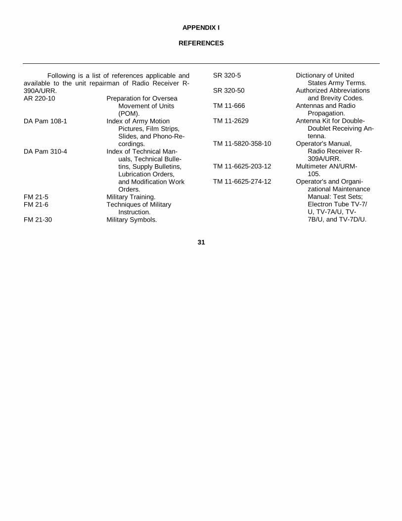
Following is a list of references applicable andavailable to the unit repairman of Radio Receiver R-390A/URR.AR 220-10 Preparation for Oversea
Movement of Units(POM).
DA Pam 108-1 Index of Army MotionPictures, Film Strips,Slides, and Phono-Re-cordings.
DA Pam 310-4 Index of Technical Man-uals, Technical Bulle-tins, Supply Bulletins,Lubrication Orders,and Modification WorkOrders.
FM 21-5 Military Training.FM 21-6 Techniques of Military
Instruction.FM 21-30 Military Symbols.
SR 320-5 Dictionary of UnitedStates Army Terms.
SR 320-50 Authorized Abbreviationsand Brevity Codes.
TM 11-666 Antennas and RadioPropagation.
TM 11-2629 Antenna Kit for Double-Doublet Receiving An-tenna.
TM 11-5820-358-10 Operator's Manual,Radio Receiver R-309A/URR.
TM 11-6625-203-12 Multimeter AN/URM-105.
TM 11-6625-274-12 Operator's and Organi-zational MaintenanceManual: Test Sets;Electron Tube TV-7/U, TV-7A/U, TV-7B/U, and TV-7D/U.
31
APPENDIX II
MAINTENANCE ALLOCATION
Section I. INTRODUCTION
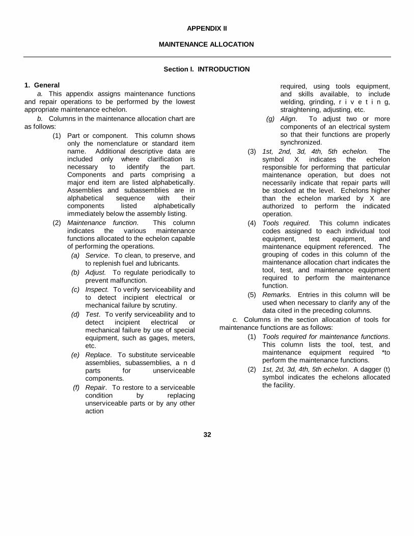
1. Generala. This appendix assigns maintenance functions
and repair operations to be performed by the lowestappropriate maintenance echelon.
b. Columns in the maintenance allocation chart areas follows:
(1) Part or component. This column showsonly the nomenclature or standard itemname. Additional descriptive data areincluded only where clarification isnecessary to identify the part.Components and parts comprising amajor end item are listed alphabetically.Assemblies and subassemblies are inalphabetical sequence with theircomponents listed alphabeticallyimmediately below the assembly listing.
(2) Maintenance function. This columnindicates the various maintenancefunctions allocated to the echelon capableof performing the operations.
(a) Service. To clean, to preserve, andto replenish fuel and lubricants.
(b) Adjust. To regulate periodically toprevent malfunction.
(c) Inspect. To verify serviceability andto detect incipient electrical ormechanical failure by scrutiny.
(d) Test. To verify serviceability and todetect incipient electrical ormechanical failure by use of specialequipment, such as gages, meters,etc.
(e) Replace. To substitute serviceableassemblies, subassemblies, a n dparts for unserviceablecomponents.
(f) Repair. To restore to a serviceablecondition by replacingunserviceable parts or by any otheraction
required, using tools equipment,and skills available, to includewelding, grinding, r i v e t i n g,straightening, adjusting, etc.
(g) Align. To adjust two or morecomponents of an electrical systemso that their functions are properlysynchronized.
(3) 1st, 2nd, 3d, 4th, 5th echelon. Thesymbol X indicates the echelonresponsible for performing that particularmaintenance operation, but does notnecessarily indicate that repair parts willbe stocked at the level. Echelons higherthan the echelon marked by X areauthorized to perform the indicatedoperation.
(4) Tools required. This column indicatescodes assigned to each individual toolequipment, test equipment, andmaintenance equipment referenced. Thegrouping of codes in this column of themaintenance allocation chart indicates thetool, test, and maintenance equipmentrequired to perform the maintenancefunction.
(5) Remarks. Entries in this column will beused when necessary to clarify any of thedata cited in the preceding columns.
c. Columns in the section allocation of tools formaintenance functions are as follows:
(1) Tools required for maintenance functions.This column lists the tool, test, andmaintenance equipment required *toperform the maintenance functions.
(2) 1st, 2d, 3d, 4th, 5th echelon. A dagger (t)symbol indicates the echelons allocatedthe facility.
32

(3) Toot code. This column lists the tool codeassigned.
(4) Remarks. Entries in this column are usedfor explanatory notes.
2. Maintenance by Using Organizations
When this equipment is used by signal serviceorganizations organic to theater headquarters orcommunications zones to provide theatercommunications, those maintenance
functions allocated up to and including fourth echelonare authorized to the organization of operating thisequipment.
3. Mounting Hardware
The basic entries of the maintenance allocationchart do not include mounting hardware, such asscrews, nuts, bolts, washers, brackets, clamps, etc.
33

Section II. MAINTENANCE ALLOCATION CHART(1) (2) (3) (4) (5) (6) (7) (8) (9)
Maintenance 1st 2nd 3rd 4th 5th ToolsPart or component function ech. ech. ech. ech. ech. required Remarks
RECEIVER, RADIO R-390A/URRservice X 11,12adjust X 7,11,12inspect Xtest X 4,5,6,8,9,10align X 1 thru 6,8,9,
10, 12, 13,14ADAPTER, CONNECTOR replace XAMPLIFIER, RADIO FREQUENCY replace X
repair XAUDIO ASSEMBLY replace X
repair XCABLE, RADIO FREQUENCY replace XCABLE, POWE ELECTRICAL replace XCAP, ELECTRICAL replace XCAPACITOR ASSEMBLY replace. XCAPACITOR, FIXED replace XCAPACUTOR, VARIABLE replace • XCAPACITOR, KIT replace XCLAMP, ELECTRICAL replace XCLIP, ELECTRICAL replace XCOLLAR SHAFT replace XCOIL, RADIO FREQUENCY replace XCONNECTOR, PLUG, ELECTRICAL replace XCONNECTOR, RECEPTACLE, ELECTRICAL replace XCONVERTER, FREQUENCY, ELECTRONIC replace X
repair XCORE, ADJUSTABLE TUNING replace XCOUNTER, ROTATING, FICED MOUNTING replace XCOUPLING, SHAFT, FLEXIBLE replace XCOVER, ELECTRICAL CONNECTOR replace XCRYSTAL UNIT, QUARTZ replace XCRYSTAL UNIT, RECTIFYING replace XDETENT, SWITCH replace XELECTRON TUBE replace XFILTER, BANDPASS replace XFILTER, RADIO INTERFERENCE replace X
R-390A/URR 1
34

Section II. MAINTENANCE ALLOCATION CHART(1) (2) (3) (4) (5) (6) (7) (8) (9)
Maintenance 1st 2nd 3rd 4th 5th ToolsPart or component function ech. ech. ech. ech. ech. required Remarks
R-390A,/URR (continued)FUSE, CARTRIDGE replace XFUSEHOLDER replace XGEAR, BEVEL replace XGEAR, BEVEL AND SPUR replace XGEAR, SPUR replace XGEAR TRAIN ASSEMBLY, RADIO FREQUENCY replace XGEAR ASSEMBLY replace XGUIDE, COUPLING replace XHOLDER, CRYSTAL UNIT replace XINSERT, ELECTRICAL, CONNECTOR repair XJACK, TELEPHONE replace XJACK TIP replace XKNOB replace XLAMP, GLOW replace XLAMP, INCANDESCENT replace XMETER, RADIO LEVEL replace XOSCILLATOR, RADIO FREQUENCY replace X
repair XOSCILLATOR, VARIABLE FREQUENCY replace X
repair XOVEN, CRYSTAL replace XOVEN, TUNED CIRCUIT replace X
repair XPLATE, GEAR, SUB-ASSEMBLY replace XPOST, BINDING replace XREACTOR replace XRECTIFIER, METALLIC replace XRELAY, ARMATURE replace XRESISTOR, FIXED replace XRESISTOR, CURRENT REGULATING replace X
R-390A/URR
35
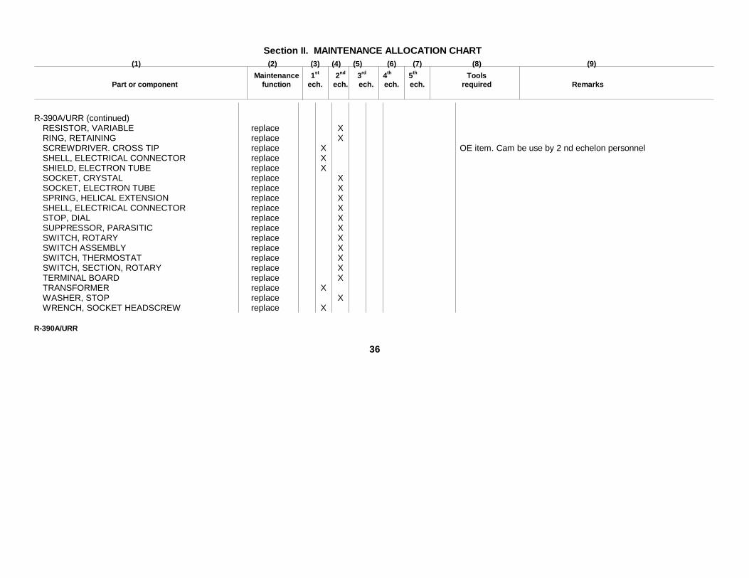
Section II. MAINTENANCE ALLOCATION CHART(1) (2) (3) (4) (5) (6) (7) (8) (9)
Maintenance 1st 2nd 3rd 4th 5th ToolsPart or component function ech. ech. ech. ech. ech. required Remarks
R-390A/URR (continued)RESISTOR, VARIABLE replace XRING, RETAINING replace XSCREWDRIVER. CROSS TIP replace X OE item. Cam be use by 2 nd echelon personnelSHELL, ELECTRICAL CONNECTOR replace XSHIELD, ELECTRON TUBE replace XSOCKET, CRYSTAL replace XSOCKET, ELECTRON TUBE replace XSPRING, HELICAL EXTENSION replace XSHELL, ELECTRICAL CONNECTOR replace XSTOP, DIAL replace XSUPPRESSOR, PARASITIC replace XSWITCH, ROTARY replace XSWITCH ASSEMBLY replace XSWITCH, THERMOSTAT replace XSWITCH, SECTION, ROTARY replace XTERMINAL BOARD replace XTRANSFORMER replace XWASHER, STOP replace XWRENCH, SOCKET HEADSCREW replace X
R-390A/URR
36

Section III. ALLOCATION OF TOOLS FOR MAINTENANCE FUNCTIONS(1) (2) (3) (4) (5) (6) (7) (8)
1st 2nd 3rd 4th 5th ToolTools Required For Maintenance Functions ech. ech. ech. ech. ech. Code Remarks
R-390A/URR (continued)ANALYZER, SPECTRUM TS-723/U 1AUDIO OSCILLATOR TS-382/U 2ELECTRON TUBE TESTER TV-2/U 3ELECTRON TUBE TESTER, TV-7/U 4FREQUENCY METER SET, 1-129 5LOUDSPEAKER LS-3 6MULTIMETER, TS-297/U 7 Replaced by AN/URM-105MULTIMETER, TS-3512 8 Replaced by AN/URM-105MULTIMETER, TS-505 9SIGNAL GENERATOR, AN/URM-2 10TOOL EQUIPMENT, TE-41 11TOOL EQUIPMENT, TE-113 12TOOL EQUIPMENT TE-114 13VOLTMETER, ME-6A/U 14 Replaced by ME-30A/U
R-390A/URR
37

BY ORDER OF THE SECRETARIES OF THE ARMY AND THE AIR FORCE:
G. H. DECKERGeneral, United States Army,
OFFICIAL: Chief of Staff.R. V. LEE,
Major General, United States Army,The Adjutant General.
THOMAS D. WHITE,OFFICIAL: Chief of Staff, United States Air Force.
J. L TARR,Colonel, United States Air Force,
Director of Administrative Services.
Distribution
Active Army:To be distributed in accordance with DA Form 12-7 requirements for TM 11 Series (UNCL) Plus the following
Formula:
USASA (2) 11-82CNGB (1) 11-57Tech 8tf, DA (1) except 11-85
CSigO (18) 11 86DASA (5) 11-98US ARADCOM (2) 11-117US ARADCOM Rgn (2) 11-155MDW (1) 11-500 (AA-AE) (4)Seventh US Army (2) 11-557EUSA (2) 11-587USASCS (69) 11-592Units org under fol TOE: (2 copies each 11-597
except as indic) 82-5111-7 82-5611-16 32-57
NG: State AG (3); Units-Same as Active Army except allowance is one copy to each unit.
USAR: None,
For explanation of abbreviations used, see AR 320-50.
*U.S. GOVERNMENT PRINTING OFFICE: 1990-261-872/21015
38

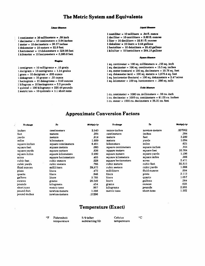

PIN: 006391-000