DEPARTMENT OF THE ARMY TECHNICAL MANUAL … · 2-4 Direct support and general support maintenance...
72
TM 5-4320-258-34 DEPARTMENT OF THE ARMY TECHNICAL MANUAL TECHNICAL MANUAL DIRECT SUPPORT AND GENERAL SUPPORT MAINTENANCE MANUAL FOR PUMP, CENTRIFUGAL, POL, GED, 6 IN., 1120 GPM SKID-MOUNTED (BARNES MODEL US67CCG) FSN 4320-409-8678 HEADQUARTERS, DEPARTMENT OF THE ARMY AUGUST 1971
-
Upload
nguyendung -
Category
Documents
-
view
214 -
download
1
Transcript of DEPARTMENT OF THE ARMY TECHNICAL MANUAL … · 2-4 Direct support and general support maintenance...

TM 5-4320-258-34
D E P A R T M E N T O F T H E A R M Y T E C H N I C A L M A N U A L
TECHNICAL MANUAL
DIRECT SUPPORT AND GENERAL SUPPORT
MAINTENANCE MANUAL
FOR
PUMP, CENTRIFUGAL, POL, GED, 6 IN., 1120 GPM
SKID-MOUNTED (BARNES MODEL US67CCG)
FSN 4320-409-8678
H E A D Q U A R T E R S , D E P A R T M E N T O F T H E A R M Y
A U G U S T 1 9 7 1

TM 5-4320-258-34
WARNING
If conditions require emergency fuel tank repairs by welding or other methods involving heat or flame, take careto assure that all gasoline fumes are purged from the tank before commencing the repair. Applying heat or flame to afuel tank containing gasoline residue may result in a violent explosion, causing injury or death to maintenance personnel.
Before performing maintenance, be sure the unit is not operating or subject to line pressures.
Do not operate the pump within an enclosed area without venting the exhaust gases to the outside. Exhaustfumes contain carbon monoxide, an odorless, colorless, deadly poison.
Do not allow smoking or open flames in the vicinity of this pump.
When lifting the pumping unit, be-sure the lifting device has a capacity of at least 4000 lbs. Do not allow thepumping unit to swing while suspended.
When using cleaning solvents, always provide adequate ventilation to prevent excessive inhalation of solventvapors.

TM 5-4320-258-34
TECHNICAL MANUAL HEADQUARTERS,DEPARTMENT OF THE ARMY
NO. 5-4320-258-34 WASHINGTON, D. C., 30 August 1971
DIRECT SUPPORT AND GENERAL SUPPORT
MAINTENANCE MANUAL
PUMP, CENTRIFUGAL, POL, GED, 6 IN., 1120 GPM,
SKID-MOUNTED
(BARNES MODEL US67CCG)
FSN 4320-409-8678
CHAPTER 1. INTRODUCTION PageSection I. General ..............................................................................................1-1
Paragraph 1-1 Scope.................................................................................................1-11-2 Forms and records .............................................................................1-11-3 Reporting of errors..............................................................................1-1
Section II. Description and data...........................................................................1-1Paragraph 1-4 Description .........................................................................................1-1
1-5 Differences between models...............................................................1-31-6 Identification and tabulated data .........................................................1-4
CHAPTER 2. DIRECT SUPPORT AND GENERAL SUPPORT MAINTENANCESection I. Repair parts, special tools, and equipment..........................................2-1
Paragraph 2-1 Special tools and equipment...............................................................2-12-2 Maintenance repair parts ....................................................................2-1
Section II. Troubleshooting..................................................................................2-1Paragraph 2-3 General ..............................................................................................2-1
2-4 Direct support and general support maintenance troubleshooting........2-1Section III. General maintenance .........................................................................2-2
Paragraph 2-5 General ..............................................................................................2-22-6 Cleanliness.........................................................................................2-22-7 Care of bearings .................................................................................2-22-8 Seals and gaskets ..............................................................................2-2
Section IV. Removal and installation of major components and auxiliaries ..........2-3Paragraph 2-9 Centrifugal pump ................................................................................2-3
2-10 Engine................................................................................................2-3
CHAPTER 3. REPAIR OF ENGINE COMPONENTSSection I. Repair of fuel system components
Paragraph 3-1 Description of fuel system...................................................................3-13-2 Fuel tank ............................................................................................3-23-3 Carburetor ..........................................................................................3-43-4 Governor ............................................................................................3-63-5 Engine overspeed governor................................................................3-8
Section II. Repair of cooling system components ..............................................3-10Paragraph 3-6 Description of cooling system ...........................................................3-10
3-7 Radiator............................................................................................3-113-8 Water pump......................................................................................3-113-9 Coolant temperature safety switch ...................................................3-13
Section III. Repair of oil system components .....................................................3-14Paragraph 3-10 Description of engine oil system .......................................................3-14
3-11 Engine oil filter .................................................................................3-143-12 Engine oil pressure safety switch .....................................................3-16
i
}

TM 5-4320-258-34
PageParagraph 3-13 Engine oil pressure adjustment .........................................................3-17
Section IV. Repair of engine mounting ...............................................................3-17Paragraph 3-14 Description ......................................................................................3-17
3-15 Engine support .................................................................................3-17
CHAPTER 4. BASIC ENGINE OVERHAULSection I. Introduction and fits, tolerances, and wear limits ................................4-1
Paragraph 4-1 Introduction.........................................................................................4-14-2 Fits, tolerances, and wear limits..........................................................4-1
Section II. Engine overhaul .................................................................................4-4Paragraph 4-3 Cylinder head ....................................................................................4-5
4-4 Intake and exhaust valves ..................................................................4-74-5 Intake and exhaust manjfolds ...........................................................4-104-6 Oil pan and filler blocks ...................................................................4-124-7 Engine oil pump................................................................................4-144-8 Gear cover .......................................................................................4-164-9 Flywheel and flywheel housing..........................................................4-184-10 Pistons and connecting rods ............................................................4-194-11 Main bearings and crankshaft ...........................................................4-234-12 Camshaft .........................................................................................4-254-13 Cylinder block ..................................................................................4-26
CHAPTER 5. REPAIR OF CENTRIFUGAL PUMPParagraph 5-1 General ..............................................................................................5-1
5-2 Check valve replacement ...................................................................5-15-3 Shaft seal replacement ......................................................................5-35-4 Centrifugal pump overhaul .................................................................5-5
APPENDIX A REFERENCES
ii

TM 5-4320-258-34
LIST OF ILLUSTRATIONS
Number Title Page
1-1 Centrifugal pump, left front view ..................................................................................1-21-2 Centrifugal pump, right rear view.................................................................................1-31-3 Wiring diagram............................................................................................................1-52-1 Engine removal ..........................................................................................................2-43-1 Operation of engine speed regulating system ..............................................................3-23-2 Fuel tank, exploded view ............................................................................................3-33-3 Carburetor, exploded view...........................................................................................3-53-4 Governor, exploded view.............................................................................................3-73-5 Engine overspeed governor, showing adjustment points .............................................3-93-6 Engine overspeed governor and related parts, exploded view .....................................3-93-7 Coolant temperature and oil pressure safety switches................................................3-103-8 Water pump, exploded view .....................................................................................3-123-9 Coolant temperature and oil pressure safety switches, exploded view .......................3-133-10 Engine oil filter mounting, exploded view ..................................................................3-153-11 Engine oil filter, exploded view ..................................................................................3-163-12 Engine mounting parts, exploded view.......................................................................3-184-1 Cylinder head, exploded view ......................................................................................4-64-2 Cylinder head cap screw tightening sequence..............................................................4-74-3 Valves and camshaft, exploded view ..........................................................................4-84-4 Valve guide installation dimensions .............................................................................4-94-5 Narrowing valve seat .................................................................................................4-104-6 Intake and exhaust manifolds, exploded view ............................................................4-114-7 Oil pan and filler blocks, exploded view .....................................................................4-134-8 Engine oil pump, exploded view ...............................................................................4-154-9 Gear cover and front end plate, exploded view .........................................................4-174-10 Checking flywheel runout ..........................................................................................4-184-11 Checking flywheel eccentricity ...................................................................................4-184-12 Checking flywheel housing runout .............................................................................4-194-13 Checking flywheel housing eccentricity ......................................................................4-194-14 Piston, crankshaft, and flywheel, exploded view .......................................................4-204-15 Checking piston fit in cylinder bore ...........................................................................4-224-16 Removing upper bearing shell with angular pin .........................................................4-234-17 Checking bearing clearance with plastigage ..............................................................4-244-18 Installing upper bearing half, using angular pin ..........................................................4-244-19 Checking bearing clearance with shim stock ..............................................................4-254-20 Timing gears showing alinement marks ....................................................................4-264-21 Checking for insufficient timing gear clearance .........................................................4-264-22 Cylinder block and flywheel housing, exploded view ..................................................4-285-1 Suction and discharge assemblies, exploded view ......................................................5-25-2 Centrifugal pump, exploded view.................................................................................5-4
iii

TM 5-4320-258-34CHAPTER 1
INTRODUCTION
SECTION I. GENERAL
1-1. ScopeThese instructions are published for use by personnel towhom the Barnes Manufacturing Company ModelUS67CCG Centrifugal Pump is issued. They provideinformation on the Direct and General maintenance ofthe equipment as allocated by the MaintenanceAllocation Chart.1-2. Forms and RecordsMaintenance forms, records, and reports which are usedby maintenance personnel at all maintenance levels arelisted in and prescribed.
1-3. Reporting of ErrorsReport of errors, omissions, and recommendations forimproving this publication by the individual user isencouraged. Reports should be submitted on DA Form2028, Recommended Changes to Publications, andforwarded directly to Commanding General, U. S.Army Mobility Equipment Command, ATTN: AMSME-MP, 4300 Good-fellow Boulevard, St. Louis, Mo.63120.
Section II. DESCRIPTION AND DATA
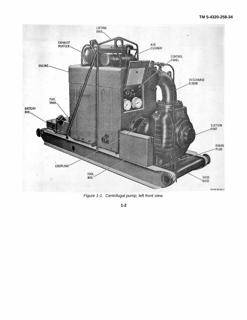
1-4.Descriptiona. Centrifugal Pump, Model US67CCG,
consists primarily of a gasoline engine and a centrifugal
pump mounted on a welded skid base. The torque fromthe engine is transferred to the pump through a flexiblecoupling.
1-1
TM 5-4320-258-34
Figure 1-1. Centrifugal pump, left front view.
1-2

TM 5-4320-258-34
Figure 1-2. Centrifugal pump, right rear view.
b. The centrifugal pump has a 6-inch suctionflange (7, fig. 5-1) secured to the front of the pumpbody and a 6-inch discharge elbow secured to the top ofthe pump body. The bearing housing (40, fig. 5-2)joins the flywheel housing of the engine with the pumpbody, providing correct spacing and proper alinement ofthe parts. The bearing housing also provides thebearing seats for the ball bearings that support theimpeller shaft. The impeller is keyed to the end of theimpeller shaft and is secured with nuts. The impeller isenclosed in a close-fitting volute to provide efficientpumping operation. A replaceable wear plate at thefront of the impeller takes most of the internal pumpwear.
c. The engine is a six-cylinder, water-cooled,pressure-lubricated, four-stroke-cycle, L-head type.Engine speed is governed by a flyball-type governor andis protected by an overspeed governor that shuts off the
engine when the engine speed reaches the presetspeed. The engine is enclosed in a housing that hascoolant and oil drains ported to the outside of thehousing for easy access. The engine uses an electricalstarting motor, has magneto ignition, and uses analternator to maintain the charge of the battery which isdepleted by operation of the starting motor. Theconventional radiator-type cooling system uses apusher-type cooling fan which forces cooling air throughthe radiator from the inside out. It also maintains a flowof air around the engine to provide proper cooling.1-5. Differences Between ModelsThis technical manual covers only the Barnes ModelUS67CCG. No known changes exist in the equipmentprocured under this model number.
1-3

TM 5-4320-258-34
1-6. Identification and Tabulated Dataa. Identification. The centrifugal pump has
three identification plates.(1) US data plate. The US data plate is
located on front of the pump above the suction flange.It indicates the pump identification number, serialnumber, dimensions, weight, and shipping information.
(2) Engine plate. The engine data plate islocated on alternator side of the engine block. Itindicates engine identification numbers, serial number,valve tappet clearance information, and patentinformation.
(3) Instruction plate. The pumpinstruction plate is located in the cover of the controlpanel. It identifies the controls and provides basicoperating instructions.
b. Tabulated Data.(1) Pump.
Manufacturer.......................Barnes ManufacturingCompany
Part number ........................US67CCGSerial number range............37628-001 thru 37628
047Type....................................CentrifugalPumping medium................Petroleum productsOutput (at maximum rated
speed) ...........................245 gpm at 205 feethead 1120 gpm at 100feet head
Maximum rated driven speed 2450 rpmSuction port size .................6 in.Discharge port size..............6 in.
(2) Engine.Manufacturer.......................Continental Motors
CorporationModel.................................. FS244-06097PType.................................... Four-stroke-cycleNumber of cylinders ............6Displacement ......................244Compression ratio ..............6.9:1Cooling ...............................LiquidCooling system capacity......18 qtsCrankcase oil capacity ........5 qtsValve clearance (warm)
Intake .............................0.014 in.Exhaust ..........................0.016 in.
Spark plug gap....................0.025 in.Breaker point gap................0.020 in.Firing order .........................1-5-3-6-2-4Governed speed..................2450 rpmOverspeed cutout................2700 rpm
(3) Engine accessories.(a) Alternator.
Manufacturer.......................Motorola
Part number ........................MA24-900GVoltage ..............................24Amperage output.................35
(b) Voltage regulator.Manufacturer.......................MotorolaPart number ........................70C44707B
(c) Starter.Manufacturer.......................Delco-RemyPart number ........................1108271Voltage ...............................24
(d) Magneto.Manufacturer.......................SlickModel No. ...........................625
(e) Fuel pump.Manufacturer.......................AC Spark PlugPart number ........................5594228
(f) Air cleaner.Manufacturer.......................DonaldsonPart number ........................FWG06-5032
(g) Oil filter.Manufacturer.......................FramPart number ........................ C7407
(4) Overall dimensions and weight.Overall length .....................111 in.Overall width.......................31 in.Overall height .....................55 in.Overall weight .....................4000 lbShipping weight...................4270 lbShipping volume .................201 cu ft
(5) Engine torque specifications.Item Torque (ft-lb)
Cylinder head bolts ............. 35-40Main bearing cap bolts ........ 85-95Flywheel nuts ...................... 35-40Manifold nuts ...................... 25-30Gear cover bolts and nuts
5/16 in ........................... 15-203/8 in .............................. 25-30
Oil pan bolts........................ 12-16Flywheel housing bolts ....... 50-55Filler block bolts ................. 15-20Front end plate bolts ........... 25-30Camshaft thrust plate bolts.. 15-20Water pump bolts ............... 25-30Magneto bolts ..................... 25-30Governor bolts .................... 25-30
(6) Wiring diagram. See figure 1-3.
1-4

TM 5-4320-258-34
Figure 1-3. Wiring diagram.
1-5

TM 5-4320-258-34
CHAPTER 2
DIRECT SUPPORT AND GENERAL SUPPORT MAINTENANCE
SECTION I. REPAIR PARTS, SPECIAL TOOLS, AND EQUIPMENT
2-1. Special Tools and EquipmentNo special tools and equipment are required for thedirect support and general support maintenance of thecentrifugal pump.2-2. Maintenance Repair PartsRepair parts and equipment are listed and illustrated in
the repair parts and special tools list covering directsupport and general support maintenance for thiscentrifugal pump. Refer to TM 5-4320-258-35P (whenprinted).
SECTION II. TROUBLESHOOTING2-3. GeneralThis section describes troubles which might occur duringoperation of the centrifugal pump, along with theprobable causes and corrective actions relating to thetroubles. Only those functions which are solely withinthe scope of direct and general support maintenance arelisted. For trouble shooting procedures which are within
the scope of operator/crew and organizationalmaintenance, refer to TM 5-4320-258-12.2-4. Direct Support and General SupportMaintenance TroubleshootingRefer to table 2-1 for troubleshooting which is allocatedto direct support and general support maintenancelevels.
Table 2-1. Troubleshooting
Malfunction Probable Cause Corrective Action1. Engine will not crank. a. Impeller binding in volute. a. Disassemble pump and free
impeller (para 5-4).b. Impeller bearings binding in b. Disassemble pump and replace
bearing housing. Bearings (para 5-4).c. Engine seized. c. Remove engine (para 2-10).
Repair engine as necessary (para4-3 through 4-13).
2. Engine cranks but will not start. a. Carburetor defective. a. Repair carburetor (para 3-3).b. Engine compression too low. b. Test engine to determine fault
(TM 5-4320-258-12). Repairengine as necessary (para 4-3through 4-13).
3. Water temperature safety switch a. Radiator clogged, causing engine a. Clean radiator (para 3-7).Stops engine operation. Overheating.
b. Cylinder head or block badly b. Clean cylinder head (Para 4-3) orscaled. Block (para 4-13).
c. Safety switch improperly adjusted. c. Adjust safety switch (para 3-9).d. Water pump defective. d. Repair water pump (para 3-8).
4. Oil pressure safety switch stops a. Oil pressure regulator valve im- a. Adjust regulator valve (para 3-engine operation. Properly adjusted. 13).
b. Oil pump defective. b. Repair oil pump (para 4-7).c. Safety switch improperly adjusted. c. Adjust safety switch (para 3-12).
5. Engine overspeed governor trips. a. Overspeed governor not properly a. Adjusted overspeed governor (paraadjusted. 3-5).
b. Overspeed governor defective. b. Replace overspeed governor (para3-5).
6. Engine lacks power, smokes, or a. Carburetor float level incorrect. a. Adjust carburetor float level (paraoperates erratically. 3-3).
b. Carburetor defective. b. Repair carburetor (para 3-3).
2-1
TM 5-4320-258-34
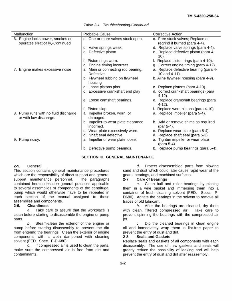
Table 2-1. Troubleshooting-Continued
Malfunction Probable Cause Corrective Action6. Engine lacks power, smokes or
operates erratically,-Continuedc. One or more valves stuck open. c. Free stuck valves; Replace or
regrind if burned (para 4-4).d. Valve springs weak. d. Replace valve springs (para 4-4).e. Defective piston e. Replace defective piston (para 4-
10).f. Piston rings worn. f. Replace piston rings (para 4-10).g. Engine timing incorrect. g. Correct engine timing (parp 4-12).
7. Engine makes excessive noise a. Main or connecting rod bearing.Defective.
a. Replace defective bearing (para 4-10 and 4-11).
b. Flywheel rubbing on flywheelhousing
b. Aline flywheel housing (para 4-9).
c. Loose pistons pins c. Replace pistons (para 4-10).d. Excessive crankshaft end play d. correct crankshaft bearings (para
4-12).e. Loose camshaft bearings. e. Replace cramshaft bearings (para
4-12).f. Piston slap. f. Replace worn pistons (para 4-10).
8. Pump runs with no fluid dischargeor with low discharge.
a. Impeller broken, worn, ordamaged.
a. Replace impeller (para 5-4).
b. Impeller-to-wear plate clearanceincorrect.
b. Add or remove shims as required(par 5-4).
c. Wear plate excessively worn. c. Replace wear plate (para 5-4).d. Shaft seal defective. d. Replace shaft seal (para 5-3).
9. Pump noisy. a. Impeller or wear plate loose. a. Tighten impeller or wear plate(para 5-4).
b. Defective pump bearings. b. Replace pump bearings (para 5-4).
SECTION III. GENERAL MAINTENANCE
2-5. GeneralThis section contains general maintenance procedureswhich are the responsibility of direct support and generalsupport maintenance personnel. The paragraphscontained herein describe general practices applicableto several assemblies or components of the centrifugalpump which would otherwise have to be repeated ineach section of the manual assigned to thoseassemblies and components.2-6. Cleanliness
a. Take care to assure that the workplace isclean before starting to disassemble the engine or pumpparts.
b. Steam-clean the exterior of the engine orpump before starting disassembly to prevent the dirtfrom entering the bearings. Clean the exterior of enginecomponents with a cloth dampened with cleaningsolvent (FED. Spec. P-D-680).
c. If compressed air is used to clean the parts,make sure the compressed air is free from dirt andcontaminants.
d. Protect disassembled parts from blowingsand and dust which could later cause rapid wear of thegears, bearings, and machined surfaces.2-7. Care of Bearings
a. Clean ball and roller bearings by placingthem in a wire basket and immersing them into acontainer of fresh cleaning solvent (FED. Spec. P-D680). Agitate the bearings in the solvent to remove alltraces of old lubricant.
b. After the bearings are cleaned, dry themwith clean, filtered compressed air. Take care toprevent spinning the bearings with the compressed airjet.
c. Dip the cleaned bearings in clean engineoil and immediately wrap them in lint-free paper toprevent the entry of dust and dirt.2-8. Seals and GasketsReplace seals and gaskets of all components with eachdisassembly. The use of new gaskets and seals willgreatly reduce the possibility of leaking and will helpprevent the entry of dust and dirt after reassembly.
2-2

TM 5-4320-258-34
SECTION IV. REMOVAL AND INSTALLATION OF MAJORCOMPONENTS AND AUXILIARIES
2-9. Centrifugal Pump,Removal and installation. of :the centrifugal pump aredescribed in2-10. Engine
a. Removal. Remove the engine from thecentrifugal pump as follows:
(1) Remove the. centrifugal pump (TM 5-4320-258-12).
(2) Disconnect the fuel lines connecting theengine to the fuel tank.
Caution: Though, thisengineis equippedwith a reverse polarity protector to protect thealternator'aigainst damage due to reverse-polarityconnectioi6ns, it is good practice to take specialprecaut-ions, when connecting and disconnectingelectrical leads and cables. Do not ground the fieldterminal between the iS alternator and regulator. Do
not operate the alternator in an open circuit with therotor winding energized. Do not ground the alter-nator output circuit. Take care to prevent reversingpolarity of the electrical system. When using abattery booster or fast charger, make sure the leadsare connected with the correct polarity. Failure tofollow these in- structions may damage therectifiers, voltage regulator, and wiring.
(3) Disconnect the battery cables at thebattery, taking care to prevent shorting, grounding, orreverse-polarizing the electrical system. Disconnect thebattery cable from the engine.
(4) Remove the nuts (1, fig. 2-1) and bevelwashers (2) that secure the lifting bail (4) to the skidbase (11); remove the lifting bail.
2-3

TM 5-4320-258-34
Figure 2-1. Engine removal.
(5) Remove the bolts (5 and 6), flatwashers (7), nuts (8), and lock washers (9) that securethe engine to the skid base. Use a suitable lift truck tolift the engine from the skid base, taking care to insertthe forks under structural members only.
b. Installation.(1) Use a lift truck to position the engine on
the skid base (11). Take care to insert the forks understructural members only. Secure the engine to the skidbase with bolts (5 and 6), nuts (8), lock washers (9), andflat washers (7).
(2) Connect the battery cables to thebattery and to the engine. Review the caution insubparagraph a above to prevent damage to thecomponents of the electrical system while connectingthe battery cables.
(3) Install the fuel lines connecting theengine to the fuel tank.
(4) Position the lifting bail (4) on the skidbase; secure with nuts (1) and bevel washers (2).
(5) Install the centrifugal pump TM 5-4320-258-12)
2-4

TM 5-4320-258-34
CHAPTER 3
REPAIR OF ENGINE COMPONENTS
SECTION I. REPAIR OF FUEL SYSTEM COMPONENTS
3-1. Description of Fuel Systema. The fuel tank is bolted to the skid at the
radiator end of the engine. It is narrow enough to ridebetween the longitudinal frame members of the skid. Ithas an offset to permit part of the tank to slide under theradiator end of the engine. The tank capacity is 30gallons.
b. Fuel from the fuel tank is pumped to thecarburetor by a fuel pump mounted on and driven by theengine. The updraft-type carburetor controls the fuel-airmixture which is fed to the engine to meet the needs ofthe engine power requirements. A float system controlsthe level of the fuel in the carburetor float bowl.Adjustment screws are provided to permit regulation ofthe high-speed operation fuel mixture, the idle mixture,and the idle speed. Choking is controlled manually.
c. Engine speed control is done by theinteroperation of the governor and the carburetor. Thegovernor is a variable-speed type and is driven by thetiming gear on the end of the camshaft. The driver onthe drive shaft of the centrifugal flyball governorengages four hardened steel balls. As the engine runs,centrifugal force tends to throw the balls outward. Asthe engine speed increases, the centrifugal forceincreases. This causes the balls to exert pressure
against a dished race, forcing the race to move , axiallyaway from the rotating balls. The movement of thedished race is transferred to a drive fork through a thrustbearing. The fork is pinned to the governing shaft whichpivots as the drive fork moves. An external governing.lever on the end of the control shaft is connected to thethrottle control onthe carburetor and as the enginespeed tends to increase, the throttle is closed slightly,resulting in a decrease in engine speed. The decreasein engine speed decreases the centrifugal force of theballs, and the dished race moves axially toward theballs. This movement is sensed by the fork which, inturn, transfers the movement to the external governinglever. The governing lever opens the carburetorthrottle, tending to speed up the engine. In this manner,a balanced condition is reached and the engine speedremains constant, keeping the engine speed at the leveldetermined by the throttle control setting. Adjustment ofthe governor'is made by changing the tension of thespring which applies tension to the external governinglever and which tends to keep the dished race againstthe flyballs. Tightening the spring tends to raise enginespeed at any particular throttle control setting.Decreasing spring tension lowers the speed.
3-1

TM 5-4320-258-34
Figure 3-1. Operation of engine speed regulating system.
d. The engine is protected from overspeedsby the overspeed governor (fig. 3-6). The overspeedgovernor is mounted on an adapter on the top center ofthe cylinder head. It is driven by a shaft which engagesthe top of the oil pump drive shaft which is, in turn,driven by a geared portion of the camshaft. Theoverspeed governor is adjusted to stop the engine ifcrankshaft speed exceeds 2700 rpm. The stopping isaccomplished by grounding the magneto primarythrough a switch which closes in the governormechanism. A reset button at the top of the overspeed
governor must be 'pressed to reset the switch if the unitit tripped by an overspeed condition.3-2. Fuel Tank
a. Removal and Disassembly.(1) Disconnect the fuel lines and fittings
from the fuel tank (TM 5-4320-258-12)(2) Remove the battery box from the skid
base.(3) Remove the drain plug (1, fig. 3-2)
from the bottom of the fuel tank and catch the fuel in asuitable container.
KEY to fig. 3-2:
1. Drain plug2. Cap screw3. Lock washer4. Fuel tank cap5. Chain6. Screen7. Nut8. Lock washer9. Fill plate10. Gasket11. Suction pipe12. Pipe plug13. Nut 114. Autofill float valve15. Fuel level gage16. Fuel tank
3-2

TM 5-4320-258-34
Figure 3-2. Fuel tank, exploded view.
3-3
TM 5-4320-258-34
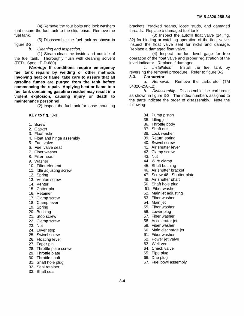
(4) Remove the four bolts and lock washersthat secure the fuel tank to the skid 'base. Remove thefuel tank.
(5) Disassemble the fuel tank as shown infigure 3-2.
b. Cleaning and Inspection.(1) Steam-clean the inside and outside of
the fuel tank. Thoroughly flush with cleaning solvent(FED. Spec. P-D-680).
Warning: If conditions require emergencyfuel tank repairs by welding or other methodsinvolving heat or flame, take care to assure that allgasoline fumes are purged from the tank beforecommencing the repair. Applying heat or flame to afuel tank containing gasoline residue may result in aviolent explosion, causing injury or death tomaintenance personnel.
(2) Inspect the fuel tank for loose mounting
brackets, cracked seams, loose studs, and damagedthreads. Replace a damaged fuel tank.
(3) Inspect the autofill float valve (14, fig.32) for binding or catching operation of the float valve.Inspect the float valve seat for nicks and damage.Replace a damaged float valve.
(4) Inspect the fuel level gage for freeoperation of the float valve and proper registration of thelevel indicator. Replace if damaged.
c. Installation. Install the fuel tank byreversing the removal procedure. Refer to figure 3-2.3-3. Carburetor
a. Removal. Remove the carburetor (TM54320-258-12).
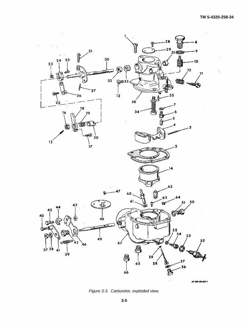
b. Disassembly. Disassemble the carburetoras shown in figure 3-3. The index numbers assigned tothe parts indicate the order of disassembly. Note thefollowing:
KEY to fig. 3-3:
1. Screw2. Gasket3. Float axle4. Float and hinge assembly5. Fuel valve6. Fuel valve seat7. Fiber washer8. Filter head9. Washer10. Filter element11. Idle adjusting screw12. Spring13. Venturi screw14. Venturi15. Cotter pin16. Retainer17. Clamp screw18. Clamp lever19. Spring20. Bushing21. Stop screw22. Clamp screw23. Nut24. Lever stop25. Swivel screw26. Floating lever27. Taper pin28. Throttle plate screw29. Throttle plate30. Throttle shaft31. Shaft hole plug32. Seal retainer33. Shaft seal
34. Pump piston35. Idling jet36. Throttle body37. Shaft nut38. Lock washer39. Return spring40. Swivel screw41. Air shutter lever42. Clamp screw43. Nut44. Wire clamp45. Shaft bushing46. Air shutter bracket47. Screw 48. Shutter plate49. Air shutter shaft50. Shaft hole plug 51. Fiber washer52. Main jet adjusting53. Fiber washer54. Main jet55. Fiber washer56. Lower plug57. Fiber washer58. Accelerator jet59. Fiber washer60. Main discharge jet61. Fiber washer62. Power jet valve63. Well vent64. Check valve65. Pipe plug66. Drip plug67. Fuel bowl assembly
3-4
TM 5-4320-258-34
Figure 3-3. Carburetor, exploded view.
3-5

TM 5-4320-258-34
(1) To remove the float axle (3), press ascrewdriver against the float axle at the slotted side ofthe float hinge bracket. Remove the axle from theopposite side and remove the float (4).
(2) After the float is removed, take carethat the fuel valve (5) does not drop from the valve seat(6).
(3) Use a file to match-mark the throttlelever (on the throttle shaft (30)) and the throttle body(36). These marks will serve as a guide to assure thatthe parts will be reassembled in the proper manner.
(4) Use a file to match-mark the air shutterbracket (46), air shutter lever (41), and the boss on thefuel bowl (67). These marks will serve as a guide toassure proper reassembly.
(5) To remove the plug (31), insert a 1/4-inch rod, 6 inches long, through the opposite side of thethrottle body (36) and drive out the shaft hole plug (31).
c. Cleaning and Inspection.(1) Clean all parts in an approved
carburetor cleaner. Wash with cleaning solvent (FED.Spec. P-D-680). Dry thoroughly with compressed air.Caution: Do not clean by inserting a wire or drill into anyopenings or passages as this will destroy their finecalibration.
(2) Blow out all passages in the air intake,fuel bowl, and throttle body with compressed air. (3)Inspect the float for cracks, worn float axle bearing,wear in the needle valve contact area, and other visibledamage. Replace the float if it is damaged or if it isloaded with gasoline.
(4) Inspect the float axle for wear on thebearing surface. Replace if any wear can bedetected.
(5) Inspect the needle valve and needlevalve seat for wear or damage. Both parts must bereplaced as an assembly if either is damaged.
(6) Inspect the idle adjusting screw fordamaged threads and for a worn needle point. Thepoint must be sharp and free from ridges of the taperedarea.
(7) Inspect the throttle plate for burrs ordamaged edges. Clean with crocus cloth to removelight burrs. Do not use a buffing wheel on the throttleplate. Replace if edges are damaged.
(8) Inspect the throttle shaft for wear of thebearing areas. Replace the shaft if visible wear isnoted.
(9) Inspect the pump lever for distortion
and for wear of the pump link hole. Replace ifdamaged.
(10) Inspect the air shutter plate fordistortion, burrs, and damaged edges. Make sure thepoppet valve on the choke plate is free. Replace adamaged choke plate.
(11) Inspect the air shutter shaft for cracks,distortion, and for worn bearing surfaces. Replace ifdamaged.
(12) Inspect the fuel bowl assembly andthrottle body for cracks, distortion, damaged threads,and other damage. Inspect the bearing surfaces of thethrottle shaft and air shutter shaft bores for wear orscoring. Replace damaged housings.
(13) Inspect all other parts for cracks,distortion, and other damage; replace damaged parts.
d. Reassembly. Refer to figure 3-3 toreassemble the carburetor. Reassembly is the reverseof disassembly. Note the following:
(1) During reassembly, aline the matchmarks made during disassembly on the fuel bowl (67),air shutter bracket (46), air shutter shaft (49), and lever(41).
(2) Aline the match marks made atdisassembly on the throttle body (36) and lever of thethrottle shaft (30).
(3) Note that the screw holes in the throttleplate (29) are off-centered. Start the side of the throttleplate with the shortest distance between the screw holesand beveled edge into place first. The plates are madewith two opposite edges beveled to fit the throttle bodybore when the plate is closed. The throttle plate will notclose tightly if installed upside down. Pressure on theplate must be maintained with the finger until the screwsare tightened. When properly installed, the side of thethrottle plate farthest away from the mounting flange willbe alined with the idle discharge holes when the plate isclosed.
e. Installation. Install and adjust thecarburetor (TM 5-4320-258-12).3-4. Governor
a. Removal. Remove the governor from theengine (TM 5-4320-258-12).
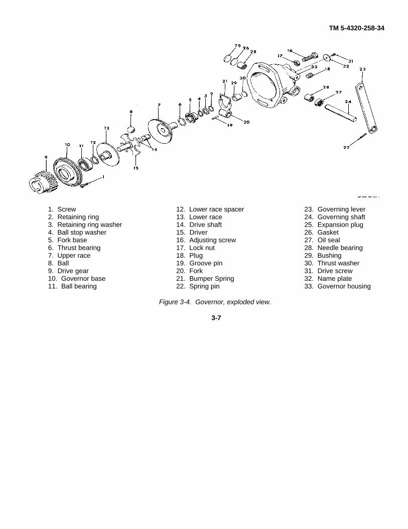
b. Disassembly. Disassemble the governor,following the sequence of numbers assigned to figure 3-4. Note the following
3-6
TM 5-4320-258-34
1. Screw2. Retaining ring3. Retaining ring washer4. Ball stop washer5. Fork base6. Thrust bearing7. Upper race8. Ball9. Drive gear10. Governor base11. Ball bearing
12. Lower race spacer13. Lower race14. Drive shaft15. Driver16. Adjusting screw17. Lock nut18. Plug19. Groove pin20. Fork21. Bumper Spring22. Spring pin
23. Governing lever24. Governing shaft25. Expansion plug26. Gasket27. Oil seal28. Needle bearing29. Bushing30. Thrust washer31. Drive screw32. Name plate33. Governor housing
Figure 3-4. Governor, exploded view.
3-7
TM 5-4320-258-34
(1) Remove the screw (1) to release thegovernor drive shaft assembly (items 2 through 15) fromthe governor housing (33).
(2) Slide the retaining ring washer (3)toward the upper race (7) on the drive shaft to exposethe retaining ring (2). Remove the retaining ring andslide the washer (3), ball stop washer (4), fork base (5),thrust bearing (6), and upper race (7) from the driveshaft assembly. This will release the four balls (8).
(3) -Support the drive gear (9) in a pressand press the drive shaft (14) from the gear. Removethe governor base (10) with the assembled bearing (11),lower race spacer (12), and the lower race (13) from theshaft.
(4) Press the ball bearing (11) from thegovernor base (10).
(5) Do not attempt to press the driver (15)from the drive shaft (14) unless either of the parts isdamaged.
(6) Drive out the groove pin (19) thatsecures the fork (20) to the governing shaft (24). Pullthe assembled governing lever (23) and shaft (24) fromthe governor housing (33) to release the fork. Removethe fork.
(7) Pierce the expansion plug (25) and pryit from the governor housing (33) along with the gasket(26).
(8) Insert a soft drift through the needlebearing (28) on the expansion plug side of the housing,and drive out the oil seal (27) and the needle bearing(28) from the housing. Insert the drift from the oppositeside and drive out the remaining needle bearing.
(9) If the bushing (29) is damaged, thread itwith a tap of suitable size and turn a bolt into thethreaded bore. Pull the assembled bolt and bushingfrom the housing (33).
c. Cleaning and Inspection.(1) Clean the bearings as directed in
paragraph 2-7.(2)'Clean all remaining parts by washing in
cleaning solvent (FED. Spec. P-D-680); dry thoroughly.(3) Inspect the bearings for rough, catching,
or binding operation. Check the balls or rollers forscoring and check the races for damage. Replacedamaged bearings.
(4). Inspect the upper race (7) and thelower race (13) for scoring, cracks, and distortion.Check the internal diameter of the bores for an out-of-round condition. Replace damaged races.
(5) Inspect the driver for scoring, cracks,wear in the ball pockets, and other damage; replace adamaged driver.
(6) Inspect the drive shaft for misalinementand for wear at the bushing end. Replace a damagedshaft.
(7) Inspect the balls (8)-for scoring, nicks,and other damage; replace damaged balls.
(8) Inspect the drive gear (9) for damagedgear teeth, worn or scored internal diameter, anddamaged drive notches; replace a damaged drive gear.
(9) Inspect the fork and bumper spring (21)for wear and distortion. Replace damaged parts.
(10) Inspect the governing shaft (24) andlever (23) for wear and distortion; replace damagedparts. (11) Inspect the governor housing (33) for cracks,damaged bores, distorted mounting flange, and otherdamage; replace a damaged body.
d. Reassembly. Reassemble the governor asshown in figure 3-4. Note the following:
(1) Lubricate all operating parts with cleanengine oil during reassembly.
(2) If the bushing (29) was removed fromthe bushing seat in the governor housing, place thethrust washer (30) in the seat and press the bushingsquarely into the seat, taking care not to damage thebushing end. Press it in until it is firmly seated againstthe thrust washer.
(3) When pressing the drive gear (9) ontothe end of the drive shaft (14), lubricate the end of theshaft with engine oil and press the gear squarely ontothe shaft. Take care to support the opposite end of theshaft in a manner which will prevent peening or burringthe shaft end.
(4) After installing the retaining ring (2), pullthe retaining ring washer (3) over the retaining ring tolock it in place.
(5) After reassembly, rotate the governorshaft. It must turn freely without binding, scraping, orcatching.
e. Installation. Install and adjust the governoron the engine (TM 5-4320-258-12).3-5. Engine Overspeed Governor
a. Testing and Adjustment. The engine over-speed governor must shut off the engine when enginespeed reaches or exceeds 2700 rpm. Test and adjustas follows:
(1) Start the. engine and allow it to warmto operating temperature, then shut it off.
(2) Disconnect the linkage from the enginespeed governor (TM 5-4320-258-12) so that the enginespeed can be controlled by manually manipulating thecarburetor throttle lever. Caution: Do not operate theengine at speeds greater than 2750 rpm. Engine over-speed can result in severe engine damage.
(3) Restart the engine and have anassistant watch the tachometer. Slowly increase enginespeed with no load until the engine stops as the result ofthe operation of the overspeed governor or until thetachometer indicates 2750 rpm.
3-8

TM 5-4320-258-34
(4) If the engine did not shut off as theresult of the tripping of the overspeed governor, theoverspeed governor requires adjustment. If the enginestopped before the tachometer indicated 2650 rpm, theengine overspeed governor must be adjusted.
(5) To adjust the engine overspeedgovernor, loosen the lock screw (3, fig. 3-5) thatsecures the cap (2) in position. To decrease the engineshutoff speed, rotate the cap clockwise. To raise theengine shutoff speed, turn the cap counterclockwise.Tighten the lock screw.
1. Reset button2. Cap3. Lock screw
Figure 3-5. Engine overspeed governor, showingadjusting points.
(6) Recheck the speed at which theoverspeed governor stops the engine as directed insteps (1) through (3) above. Readjust until the engineshuts off at 2700 rpm. Replace the engine overspeedgovernor if it cannot be adjusted.
(7) Reconnect the engine speed governor.b. Removal.
(1) Remove the tachometer drive from thegovernor arm (TM 5-4320-258-12)
(2) Disconnect the electrical leads from theterminals at the top of engine overspeed governor. Tagleads to facilitate reassembly.
(3) Remove and disassemble theoverspeed governor and related parts as shown in figure3-6.
1. Cap screw2. Lock washer3. Overspeed governor4. Cap screw5. Lock washer6. Governor arm7. Nut8. Lock washer9. Cap screw10. Adapter11. Governor drive shaft
Figure 3-6. Engine overspeed governor and relatedparts, exploded view.
c. Cleaning and Inspection.(1) Wipe the exterior of the engine
overspeed governor with a cloth dampened withcleaning solvent (FED. Spec. P-D-680); dry thoroughly.Take care to prevent solvent from entering the interiorof the unit.
(2) Wash all remaining parts with cleaningsolvent (FED. Spec. P-D-680). Remove the grease
3-9

TM 5-4320-258-34
cup from the governor arm and carefully remove allgrease from the cup and from the interior of the arm.
(3) Remove all grease from the toothedportion of the governor drive shaft. Use a soft- bristledbrush, if necessary, to remove the grease.
(4) Inspect the engine overspeed governorfor cracks, loose or damaged terminals, and damagedcoupling at the end of the shaft. Rotate the shaft tocheck for rough, catching, or binding operation.Replace a damaged overspeed governor.
(5) Inspect the governor drive shaft forcracks, damaged teeth, distortion and other damage;replace a damaged drive shaft.
(6) Inspect all other parts for cracks,
distortion, damaged threads, and other damage; replacedamaged parts.
d. Reassembly and Installation.(1) Reassemble and install the engine
overspeed governor and related parts as shown 'infigure 3-6.
(2) Reconnect the electrical leads to theterminals at the top of the overspeed governor.
(3) Reconnect the tachometer drive andtachometer shaft to the governor arm, and lubricate thetachometer drive and overspeed governor (TM 5-4320-258-12).
(4) Check and, if necessary, adjust theengine overspeed governor (subparagraph a above).
SECTION II. REPAIR OF COOLING SYSTEM COMPONENTS
3-6. Description of Cooling Systema. Liquid coolant is pumped around the
cylinder walls and valve guides in the cylinder block andaround the tops of the cylinders in the cylinder head toremove the heat of combustion from the engine. This isnecessary to prevent the excessive heat from damagingthe engine.
b. As the hot coolant is pumped from theengine, it enters the radiator consisting of tubes and finswhich dissipate the heat to the atmosphere. The fluidpasses into the top of the radiator and out through thebottom. The cooling fan maintains a blast of air throughthe radiator to help dissipate the heat.
c. The coolant from the radiator enters thewater pump which is V-belt driven by the engine tocirculate the coolant through the block and cylinder headto complete the cycle. The centrifugal water pump ismounted on the cylinder block.
d. The engine is protected from overheatingby coolant temperature safety switch (2, fig. 3-7)mounted on the control panel. This switch closes a setof contacts to stop the engine by grounding the magnetoprimary before engine coolant tem- perature reaches thepoint that engine damage can occur. The switch trippoint is adjustable.
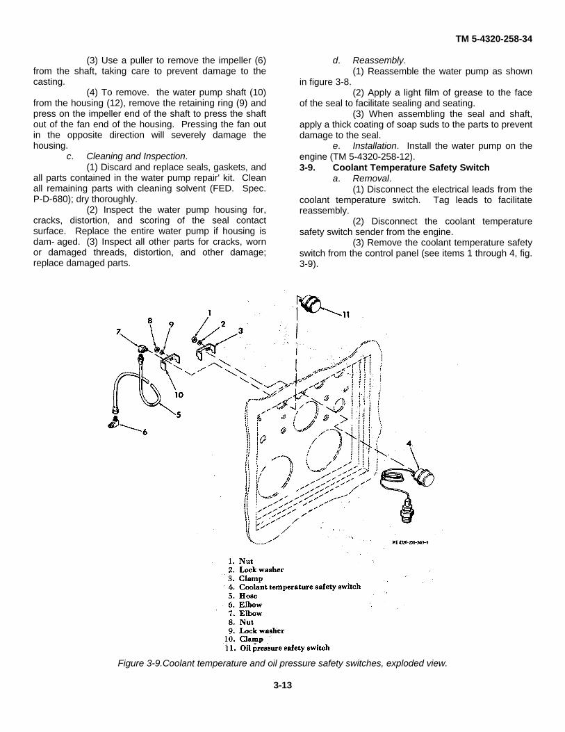
1. Oil pressure safety switch2. Coolant temperature safety switch3. Temperature switch adjusting screw4. Oil pressure switch adjusting screw5. Oil safety switch pushbutton
Figure 3-7. Coolant temperature and oil pressure safetyswitches.
3-10

TM 5-4320-258-34
3-7. Radiatora. Removal. Remove the radiator (TM 5-
4320- 258-12).b. Cleaning.
(1) Clean the exterior of the radiator byflushing in a reverse-flow direction with stream of waterto remove all bugs and debris. Remove any greasy oroily deposits with cleaning solvent (FED. Spec. P-D-680).
(2) Reverse-flush the interior of theradiator, using a flushing gun.
c. Inspection and Testing.(1) Inspect all parts for cracks, signs of
leaking tubes or gaskets, damaged thread's, or otherobvious damage.
Caution: Do not exceed 10 psi air pressurefor radiator testing. Excess pressure will damagethe radiator. Be sure' the radiator core iscompletely drained before testing. When testing atlow pressure, it is possible that water within thecore could prevent air from passing out of smallholes, and the leak could pass undetected.
(2) Make sure the radiator is completelydrained of coolant. Plug all openings, except onethrough which compressed air can be applied. Immerse
the radiator in a tank of water and apply 10 psi airpressure to the interior of the radiator. Check for airbubbles that could indicate a leak. If a leak is found,mark the area for repair.
(3) Inspect all hardware for cracks and forworn or stripped threads.
(4) Replace all parts damaged beyondrepair.
d. Repair.(1) Repair leaks by soldering. Be sure that
the repair does not block or retard circulation throughany tubes. There shall be no blocked tubes.
(2) Straighten any bent or damaged fins.Replace any damaged parts.
e. Installation. Install the radiator (TM 5-4320-258-12).3-8. Water Pump
a. Removal. Remove the water pump fromthe engine (TM 5-4320-258-12).
b. Disassembly.(1) Disassemble the water pump only if the
shaft binds, the seal leaks, the housing is cracked ordamaged, or there are other signs of faulty operation.
(2) Use a puller to pull the drive pulley (2,fig. 3-8) from the water pump
3-11

TM 5-4320-258-34
Figure 3-8. Water pump, exploded view
3-12
TM 5-4320-258-34
(3) Use a puller to remove the impeller (6)from the shaft, taking care to prevent damage to thecasting.
(4) To remove. the water pump shaft (10)from the housing (12), remove the retaining ring (9) andpress on the impeller end of the shaft to press the shaftout of the fan end of the housing. Pressing the fan outin the opposite direction will severely damage thehousing.
c. Cleaning and Inspection.(1) Discard and replace seals, gaskets, and
all parts contained in the water pump repair' kit. Cleanall remaining parts with cleaning solvent (FED. Spec.P-D-680); dry thoroughly.
(2) Inspect the water pump housing for,cracks, distortion, and scoring of the seal contactsurface. Replace the entire water pump if housing isdam- aged. (3) Inspect all other parts for cracks, wornor damaged threads, distortion, and other damage;replace damaged parts.
d. Reassembly.(1) Reassemble the water pump as shown
in figure 3-8.(2) Apply a light film of grease to the face
of the seal to facilitate sealing and seating.(3) When assembling the seal and shaft,
apply a thick coating of soap suds to the parts to preventdamage to the seal.
e. Installation. Install the water pump on theengine (TM 5-4320-258-12).3-9. Coolant Temperature Safety Switch
a. Removal.(1) Disconnect the electrical leads from the
coolant temperature switch. Tag leads to facilitatereassembly.
(2) Disconnect the coolant temperaturesafety switch sender from the engine.
(3) Remove the coolant temperature safetyswitch from the control panel (see items 1 through 4, fig.3-9).
Figure 3-9.Coolant temperature and oil pressure safety switches, exploded view.
3-13

TM 5-4320-258-34
b. Cleaning and Inspection.(1) Wipe the coolant temperature safety
switch with a cloth dampened with cleaning solvent(FED. Spec. P-D-680); dry thoroughly.
(2) Inspect the coolant temperature safetyswitch for broken, loose, or corroded terminals, severedents, and other obvious damage. Check and adjust theswitch as directed in subparagraph c below.
c. Testing and Adjustment.(1) Suspend the sender of the coolant
temperature safety switch and a thermometer in acontainer so that neither the sender nor the thermometertouches the sides or bottom of the container. Connect amultimeter, set to read continuity, across the terminals
of the switch. No continuity should be indicated atnormal temperatures.
(2) Heat the container while watching thethermometer and the multimeter. As the watertemperature reaches approximately 2100F, themultimeter should indicate continuity through the switch.
(3) If the switch remains open, or closes attoo low a temperature, loosen the lock nut on theadjusting screw (3, fig. 3-7) and adjust the switch sothat it just closes at 2100F. Lock the lock nut to securethe adjustment.
d. Installation. Installation is the reverse ofremoval. Refer to items I through 4 in figure 3-9. Ifnecessary, refer to the wiring diagram, figure 1-3, forwiring connection information.
SECTION III. REPAIR OF OIL SYSTEM COMPONENTS
3-10. Description of Engine Oil Systema. The engine oil system provides lubrication
for the working surfaces within the engine. The oil isretained in the oil pan under the engine and is circulatedthrough the engine by the oil pump mounted on one ofthe main bearing caps of the engine. Internalcomponents of the engine lubrication system arecovered in chapter 4, which describes basic engineoverhaul. Oil pressure ad- justment is described inparagraph 3-13.
b. An oil filter with its related piping ismounted on the exterior of the engine to remove fromthe engine oil impurities and particles that could causeengine wear. This filter has a replaceable-typecartridge.
c. The engine is protected from a low oilpressure condition by an oil pressure safety switch (1,fig. 3- 7) mounted on the engine control panel. Thisswitch is adjustable and provides a reset push- button toreset the device for starting.3-11. Engine Oil Filter
a. Removal.(1) Drain the oil from the engine (TM 5-
4320-258-12).(2) Disconnect the electrical lead from the
oil pressure sender on the filter piping.(3) Remove the oil filter and related parts
from the engine as shown in figure 3-10
3-14

TM 5-4320-258-34
Figure 3-10. Engine oil filter mounting, exploded view.
3-15


TM 5-4320-258-34
Blow through the hose with compressed air to makesure it is not clogged.
(3) Inspect the, :oil pressure safety switchfor cracks, dents, damaged threads, and loose orcorroded electrical terminals; replace if damaged.
(4) Inspect the hose for abrasions,deterioration, and damaged threads; replace a damagedhose.
(5) Inspect the remaining parts for cracks,damaged threads, distortion, and other damage; replacedamaged parts.
c. Adjustment and Testing.(1) Connect the pressure inlet of the oil
pressure safety switch/ to an adjustable and calibratedair pressure source. Connect a multimeter, adjustedto read continuity, across the electrical terminals.
(2) Under a no-pressure condition, pressand release the oil safety switch pushbutton (5, fig. 3-7)while watching the multimeter. It must indicate nocontinuity after the safety switch pushbutton is pressed.
(3) With the safety switch pushbutton re- leased,slowly apply pressure to the oil pressure safety switchwhile watching the multimeter. Continue to increasepressure to approximately 60 psi and then slowlydecrease pressure while noting the indication of themultimeter. As pressure is decreased to between 5 and6 psi, continuity must be made through the switch.Continuity must be broken as the oil pressure safetyswitch pushbutton is pressed.
(4) If the switch fails to close between 5and 6 psi, turn the adjusting screw (4, fig. 3-7) on theswitch to adjust the switch closing to the required level.
(5) Recheck the adjustment and, ifnecessary, repeat until the proper closing point isattained.
d. Installation. Installation of the oil pressuresafety switch is the reverse of removal. Refer to items 6through 11 of figure 3-9. If necessary, refer to the wiringdiagram (fig. 1-3) for wire connection information.3-13. Engine Oil Pressure Adjustment
a. Description. The engine oil pressure isregulated by a relief valve mounted in the enginecylinder block. It consists mainly of a spring- loaded,spool-type valve which seats in a bore in the block. Thegreater the spring pressure which loads the valve, thegreater is the oil pressure in the system. The pressureis increased by adding pressure-adjusting washersbetween the spring and the valve to increase springforce against the valve.
b. Adjustment.(1) Start the engine and allow it to warm to
operating temperature. Check the engine oil pressureindicated on the oil pressure gage. At idle speed, thepressure must exceed 7 psi; at governed speed it mustbe between 20 and 30 psi.
(2) If the engine oil pressure is not withinthe required range, shut off the engine and remove theplug (23, fig. 4-22) from the carburetor side of theengine block. Remove the relieve valve spring (25) andpressure adjusting washers (26).
(3) To increase oil pressure, add a washerbetween the spring and valve. Not more than fourwashers are allowed. If four washers fail to bring it intothe required range, the spring is faulty or other enginetroubles exist.
(4) After adjustment, check that the oilpressure remains in the required ranges duringoperation.
SECTION IV. REPAIR OF ENGINE MOUNTING
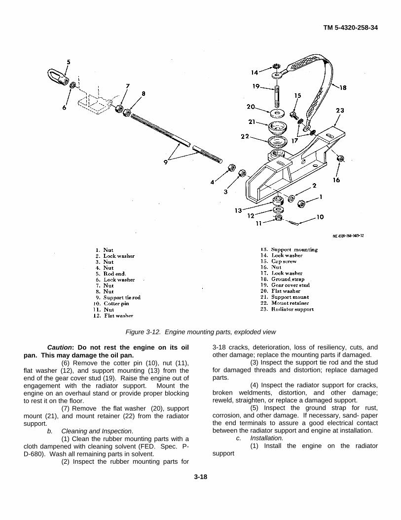
3-14. DescriptionThe engine is mounted on the radiator support assemblyat the front, and on the feet of the flywheel housing atthe rear. The resilient support at the front of the enginehelps cushion the engine vibration, preventing it frombeing transmitted to the associated equipment. Theradiator support is connected to the flywheel housing byadjustable tie rods.3-15. Engine Support
a. Removal.
(1) Remove the engine from the centrifugalpump assembly (para 2-10).
(2) Remove the engine housing from theengine (TM 5-4320-258-12).
(3) Remove the radiator (TM 5-4320-258--12).
(4) Support the engine with a hoist engagedin the lifting eye at the top of the engine.
(5) Remove the tie rods and related parts(items 1 through 9, fig. 3-12) that connect the radiatorsupport (23) with the flywheel housing
3-17
TM 5-4320-258-34
Figure 3-12. Engine mounting parts, exploded view
Caution: Do not rest the engine on its oilpan. This may damage the oil pan.
(6) Remove the cotter pin (10), nut (11),flat washer (12), and support mounting (13) from theend of the gear cover stud (19). Raise the engine out ofengagement with the radiator support. Mount theengine on an overhaul stand or provide proper blockingto rest it on the floor.
(7) Remove the flat washer (20), supportmount (21), and mount retainer (22) from the radiatorsupport.
b. Cleaning and Inspection.(1) Clean the rubber mounting parts with a
cloth dampened with cleaning solvent (FED. Spec. P-D-680). Wash all remaining parts in solvent.
(2) Inspect the rubber mounting parts for
3-18 cracks, deterioration, loss of resiliency, cuts, andother damage; replace the mounting parts if damaged.
(3) Inspect the support tie rod and the studfor damaged threads and distortion; replace damagedparts.
(4) Inspect the radiator support for cracks,broken weldments, distortion, and other damage;reweld, straighten, or replace a damaged support.
(5) Inspect the ground strap for rust,corrosion, and other damage. If necessary, sand- paperthe end terminals to assure a good electrical contactbetween the radiator support and engine at installation.
c. Installation.(1) Install the engine on the radiator
support
3-18

TM 5-4320-258-34
as shown in figure 3-12. Make sure the ground strap(18) is making good electrical contact between parts.
(2) When installing the tie rods (9) thatconnect the radiator support with the flywheel housing,position the inner nuts so that they prevent excessivestrain on the radiator support when the outer nuts aretightened. The bottom of the radiator support must be
horizontal when the tie rods are installed..(3) Install the radiator (TM 5-4320-258-12).(4) Install the engine housing (TM 5-4320-
258-12).(5) Install the engine on the centrifugal
pump assembly (para 2-10).
3-19

TM 5-4320-258-34
CHAPTER 4
BASIC ENGINE OVERHAUL
SECTION I. INTRODUCTION AND FITS, TOLERANCES,AND WEAR LIMITS
4-1. IntroductionThis chapter provides instructions relating to enginerepair and overhaul. It includes information regardingdisassembly, inspection of parts to determine if theircontinued serviceability is possible or if they should bereplaced, instructions covering repair techniques suchas valve grinding and cylinder honing, reassembly andtolerance checking to assure proper fits and clearances,and all other information relating to engine overhaul.
Paragraph 4-2 provides the fits, tolerances, andallowable wear limits which are useful in determining ifparts replacement is necessary.
4-2. Fits, Tolerances, and Wear LimitsTable 4-1 lists the fits and tolerances applicable to theengine. Refer to the table to determine if partsreplacement is required or if containued serviceability ofthe parts is possible.
4-1

TM 5-4320-258-34
Table 4-1. Engine Fits, Tolerances, and Wear Limits
Manufacturer's dimensions Design clearances AllowableComponent points of measurement and tolerances in inches in inches wear or
Minimum Maximum, Minimum Maximum clearance
Valve and valve guidesIntake valves
Cylinder block face-to-guide distance 115/32Outside diameter 0.6565 0.6575Inside diameter 0.3422 0.3432 0.3447Valve stem diameter 0.3406 0.3414 0.3386Stem-to-guide clearance 0.0008 0.0026 0.0046Valve tappet clearance 0.0140
Exhaust valvesCylinder block face-to-guide distance 115/32Outside diameter 0.6565 0.6575Inside diameter 0.3422 0.3432 0.3447Valve stem diameter 0.3377 0.3385 0.3357Stem-to-guide clearance 0.0037 0.0055 0.0075Valve tappet clearance 0.0160 (Hot)
0.0170 (Cold}Valve tappets
Outside diameter 0.9990Tappet bore diameter 1.0000Maximum bore-to-tappet clearance 0.0050
Camshaft and bushingsBearing journal diameter
No. 1 1.8715 1.8725 1.8705No. 2 1.8085 1.8095 1.8075No. 3 1.7457 1.7465 1.7447No. 4 1.2465 1.2475 1.2455
Camshaft bushing diameterNo. 1 1.8745 1.8755No. 2 1.8115 1.8125No. 3 1.7495 1.7502No. 4 1.2495 1.2505
Journal-to-bushing clearanceNo. 1 0.0020 0.0040No. 2 0.0020 0.0040No. 3 0.0020 0.0040No. 4 0.0020 0.0040
Camshaft end play 0.0050 0.0090Connecting rod
Bushing hole diameter 0.9130 0.9140Bearing hole diameter 2.1865 2.1870Side play 0/0060 0.0100
Connecting rod bearingBearing hole diameter 2.1865 2.1870Bearing thickness 0.0613 0.0616 0.0608Crankpin diameter 2.0619 2.0627 2.0609Bearing to crankshaft clearance 0.0032
CrankshaftEnd thrust 0.0030 0.0080Main bearing journal diameter 2.3744 2.3752 2.3734Crankpin diameter 2.0619 2.0627 2.0609
Main bearingsCase hole 2.5615 2.5622Bearing thickness 0.0925 0.0928 0.0920Crankshaft journal diameter 2.3744 2.3752 2.3734Journal-to-bearing clearance 0.0007 0.0028
PistonRing groove width
1st 0.1270 0.1290 0.13052nd and 3rd 0.1275 0.1285 0.13054th 0.2520 0.2530 0.2550
Cylinder bore diameter 3.4375 3.4395 3.4475Piston fit in bore. Check by pull on 1/ 3-inch 5-10 lb
wide-0.003-inch feeler gage
4-2

TM 5-4320-258-34
Manufacturer's
dimensions
Design clearances
Allowable
Component points of measurement andtolerances
in inches in inches wear or
Minimum Maximum,
Minimum
Maximum
clearance
Piston ringsWidth
No. 1 0.1230 0.1240 0.1210No. 2 and 3 0.1235 0.1240 0.1215No. 4 0.2485 0.2490 0.2465
GapNo. 1 0.0070 0.0170No. 2 and 3 0.0070 0.0170No. 4 0.0070 0.0170
Side clearanceNo. 1 0.0035 0.0050No. 2 and 3 0.0035 0.0055No. 4 0.0030 0.0045
Piston pinLength 2.8050 2.8150Pin diameter 0.8591 0.8593 0.8607Piston pin bushing diameter 0.8595 0.8597 0.8067Piston pin fit in piston Light PushPiston pin fit in rod 0.0002 0.0006
Valve spring (intake and exhaust)Weight required to compress to 145/64 in.
47 lb 53 lb 42 lb
Weight required to compress to 127/64 in.
96 lb 104 lb 86 lb
4-3
TM 5-4320-258-34
SECTION II. ENGINE OVERHAUL
Note. Some engine repair can be done with theengine in the engine housing. More extensive repair willrequire removal of the engine from the housing. Majorrepair or overhaul requires that the engine be mountedon an engine overhaul stand. Remove the enginehousing (TM 5-4320-258-12). Remove the engine fromits mounting parts if necessary (para 3-15). Remove
accessories from the engine as required. Refer to TM5-4320-258-12.
4-3. Cylinder Heada. Removal. Remove the cylinder head and
gasket as shown in figure 4-1.
4-4

TM 5-4320-258-34
Figure 4-1. Cylinder head, exploded view.
4-5
TM 5-4320-258-34
b. Cleaning and Inspection.(1) Remove all carbon from combustion
areas with a scraper and wire brush. Clean allremaining residue from the cylinder head with cleaningsolvent (FED. Spec. P-D-680). Dry with clean, drycompressed air.
(2) Clean the top of the cylinder block witha scraper and a cloth dampened in cleaning solvent(FED. Spec. P-D-680). Be very careful not to get dirtin the cylinders or water jacket.
(3) Inspect the cylinder head for cracks,corrosion, damaged threads, plugged water ports, orother defects.
(4) Check flatness lengthwise with astraightedge and feeler gage. The maximum,permissible low spot is 0.012 inch in the center,
gradually decreasing toward the ends. Check flatnesslengthwise at each edge and in the middle of the head.
(5) Check flatness crosswise with astraightedge and a feeler gage. The maximumpermissible low spot is 0.003 inch in localized areas.Check flatness crosswise at each end and between eachcombustion chamber.
(6) Inspect cylinder head studs forlooseness or damaged threads.
(7) Replace the gasket, hoses, anddefective parts.
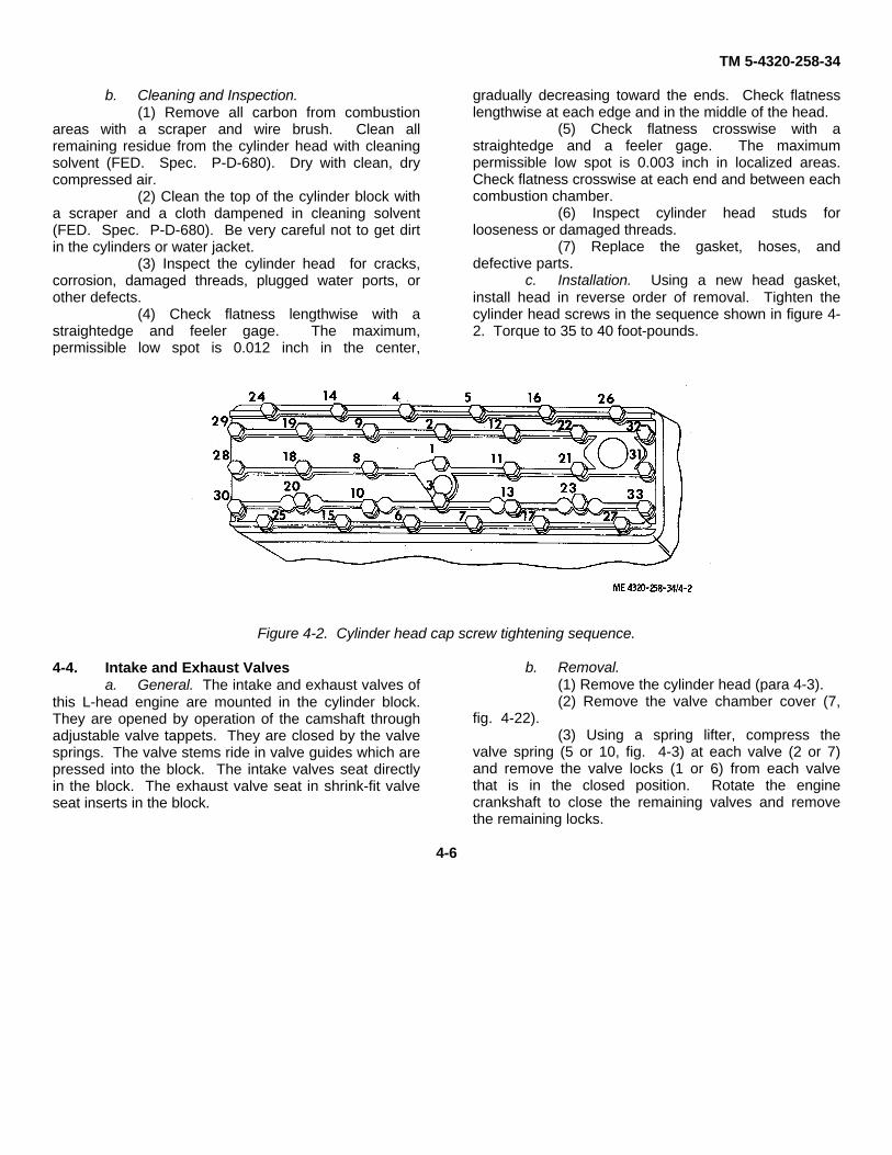
c. Installation. Using a new head gasket,install head in reverse order of removal. Tighten thecylinder head screws in the sequence shown in figure 4-2. Torque to 35 to 40 foot-pounds.
Figure 4-2. Cylinder head cap screw tightening sequence.
4-4. Intake and Exhaust Valvesa. General. The intake and exhaust valves of
this L-head engine are mounted in the cylinder block.They are opened by operation of the camshaft throughadjustable valve tappets. They are closed by the valvesprings. The valve stems ride in valve guides which arepressed into the block. The intake valves seat directlyin the block. The exhaust valve seat in shrink-fit valveseat inserts in the block.
b. Removal.(1) Remove the cylinder head (para 4-3).(2) Remove the valve chamber cover (7,
fig. 4-22).(3) Using a spring lifter, compress the
valve spring (5 or 10, fig. 4-3) at each valve (2 or 7)and remove the valve locks (1 or 6) from each valvethat is in the closed position. Rotate the enginecrankshaft to close the remaining valves and removethe remaining locks.
4-6
TM 5-4320-258-34
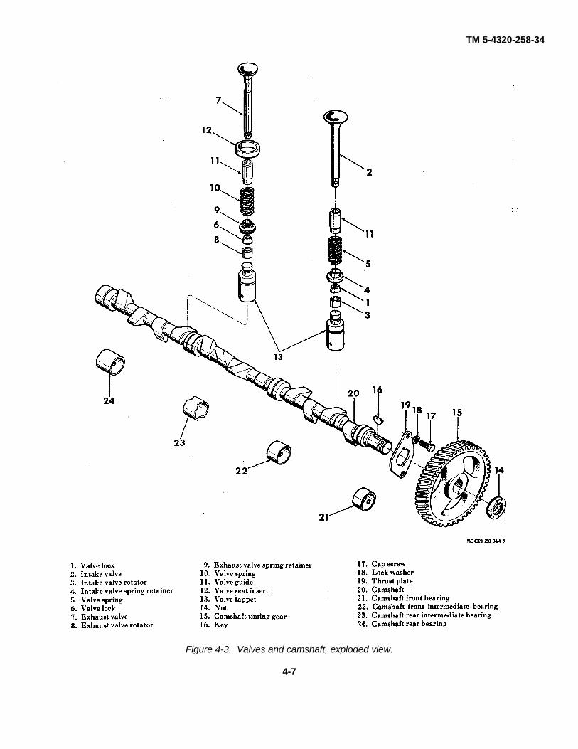
Figure 4-3. Valves and camshaft, exploded view.
4-7

TM 5-4320-258-34
(4) Lift each valve from the top of theblock. Place valves in order in a rack to assure thateach will be reassembled in the same valve guide fromwhich it was removed.
(5) Remove the valve rotators (3 or 8),spring retainers (4 or 9), and valve springs (5 or 10).Remove the valve tappet assemblies (13).
(6) Do not remove the valve guides (11) orvalve seat inserts (12) unless inspection indicates thatthey are faulty.
c. Cleaning, Inspection, and Repair.(1) Clean the valves, valve springs, and
valve tappet assemblies with cleaning solvent (FED.Spec. P-D-680); dry thoroughly. Remove carbondeposits with a wire brush.
(2) Clean the valve guides installed in theblock with a valve guide cleaner or wire brush. Removeall lacquer and other deposits.
(3) Clean the valve seats with a wire brush.(4) Inspect the valves for cracks, bent
stems, distortion, and wear (table 4-1). If the valves arenot seriously damaged, regrind them. After grinding, thevalve head thickness must be at least 50 percent thethickness of a new valve. Replace the valves if they areground to less than this amount. Check the regroundvalves on V-blocks with an indicator. The contact facemust be true with the stem to within 0.002 inch.
(5) Check for loose or worn valve guides.Check the internal diameter of the valve guide with atelescope gage and a micrometer. Replace guides thatare worn to a bell-mouthed shape or guides that have amaximum diameter of more than 0.3447 inch.
Caution: Do not attempt to ream the valveguides after seating them. Guides are pre reamedand coated. Further reaming will remove thecoating.
(6) If the valve guides are worn ordamaged, press out the guides from the combustionside, using a driver that is slightly smaller than theexternal diameter of the guide. With the driver, press innew guides from the combustion side. When properlyseated, valve guide tops will be 1 13 / 32 inches fromthe top of the block (fig. 4-4).
Figure 4-4. Valve guide installation dimensions.
(7) Check the exhaust valve seat insertsfor cracks or loose mounting. Pull out faulty valve seatinserts. Replace original valve seats with new 0.010-inch oversized valve seats. Counterbore the originalvalve seats to a diameter of 1.3535 to 1.3545 inches.This will provide the required press fit. If valve seatshave been counterbored previously, rebore to 0.01 inchoversize to provide an 0.003- to 0.005-inch press fit.Counterbore deeply enough so that the boring tool willclean up the bottom of the bore to assure proper heatconduction from the valve insert. Chill the valve seatsin dry ice for 20 minutes. Install the valve seat in placewith a piloted driver, using an arbor press or by applyinglight blows with a hammer until the valve seat is restingagainst the bottom of the bore. Roll or peen the valveseat in place.
(8) Check the valve springs for cracks anddistortion. Intake and exhaust valve springs areidentical. Test compression strength with a springtester. Compression strength must be as follows:
4-8
TM 5-4320-258-34
Length Load (minimum)1-45 / 64 inches (closed) 42 pounds1-27 / 64 inches (open) 86 pounds
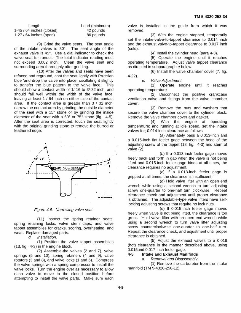
(9) Grind the valve seats. The seat angleof the intake valves is 30°. The seat angle of theexhaust valve is 45°. Use a dial indicator to check thevalve seat for runout. The total indicator reading mustnot exceed 0.002 inch. Clean the valve seat andsurrounding area thoroughly after grinding.
(10) After the valves and seats have beenrefaced and reground, coat the seat lightly with Prussianblue 'and drop the valve into place, oscillating it slightlyto transfer the blue pattern to the valve face. Thisshould show a contact width of 1/ 16 to 3/ 32 inch, andshould fall well within the width of the valve face,leaving at least 1 / 64 inch on either side of the contactarea. If the contact area is greater than 3 / 32 inch,narrow the contact area by grinding the outside diameterof the seal with a 15° stone or by grinding the insidediameter of the seat with a 60° or 75° stone (fig. 4-5).After the seat area is corrected, touch the seat lightlywith the original grinding stone to remove the burred orfeathered edge.
Figure 4-5. Narrowing valve seat.
(11) Inspect the spring retainer seats,spring retaining locks, valve stem caps, and valvetappet assemblies for cracks, scoring, overheating, andwear. Replace damaged parts.
d. Installation.(1) Position the valve tappet assemblies
(13, fig. 4-3) in the engine block.(2) Assemble-the valves (2 and 7), valve
springs (5 and 10), spring retainers (4 and 9), valverotators (3 and 8), and valve locks (1 and 6). Compressthe valve springs with a spring compressor to install thevalve locks. Turn the engine over as necessary to alloweach valve to move to the closed position beforeattempting to install the valve parts. Make sure each
valve is installed in the guide from which it wasremoved.
(3) With the engine stopped, temporarilyset the intake-valve-to-tappet clearance to 0.014 inchand the exhaust valve-to-tappet clearance to 0.017 inch(cold).
(4) Install the cylinder head (para 4-3).(5) Operate the engine until it reaches
operating temperature. Adjust valve tappet clearanceas directed in subparagraph e below.
(6) Install the valve chamber cover (7, fig.4-22).
e. Valve Adjustment.(1) Operate engine until it reaches
operating temperature.(2) Disconnect the positive crankcase
ventilation valve and fittings from the valve chambercover.
(3) Remove the nuts and washers thatsecure the valve chamber cover to the cylinder block.Remove the valve chamber cover and gasket.
(4) With the engine at operatingtemperature: and running at idle speed, set the intakevalves for; 0.014-inch clearance as follows:
(a) Alternately pass a 0.013-inch anda 0.015-inch flat feeler gage between the head of theadjusting screw of the tappet (13, fig. 4-3) and stem ofvalve (2).
(b) If a 0.013-inch feeler gage movesfreely back and forth in gap when the valve is not beinglifted and 0.015-inch feeler gage binds at all times, theclearance requires no adjustment.
(c) If a 0.013-inch feeler gage isgripped at all times, the clearance is insufficient.
(d) Hold valve lifter with an open endwrench while using a second wrench to turn adjustingscrew one-quarter to one-half turn clockwise. Repeatclearance check and adjustment until proper clearanceis obtained. The adjustable-type valve lifters have self-locking adjusting screws that require no lock nuts.
(e) If 0.015-inch feeler gage movesfreely when valve is not being lifted, the clearance is toogreat. 'Hold valve lifter with an open end wrench whileusing a second wrench to turn valve lifter adjustingscrew counterclockwise one-quarter to one-half turn.Repeat the clearance check, and adjustment until properclearance is obtained.
(5) Adjust the exhaust valves to a 0.016(hot) clearance in the manner described above, using0.015and 0.017-inch feeler gage.4-5. Intake and Exhaust Manifolds
a. Removal and Disassembly.(1) Remove the carburetor from the intake
manifold (TM 5-4320-258-12).
4-9
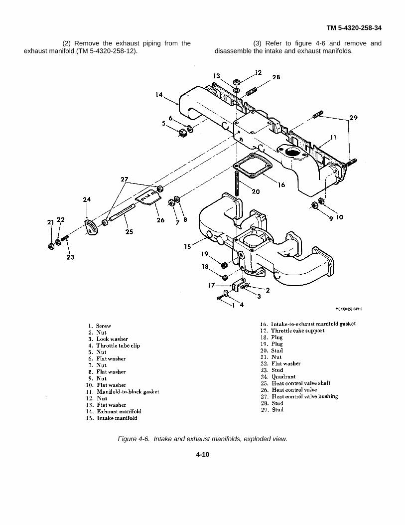
TM 5-4320-258-34
(2) Remove the exhaust piping from theexhaust manifold (TM 5-4320-258-12).
(3) Refer to figure 4-6 and remove anddisassemble the intake and exhaust manifolds.
Figure 4-6. Intake and exhaust manifolds, exploded view.
4-10

TM 5-4320-258-34
b. Cleaning and Inspection.(1) Discard and replace all gaskets.(2) Clean the intake manifold and heat
control valve and related parts with cleaning solvent(FED. Spec. P-D-680). Dry thoroughly.
(3) Clean the exhaust manifold with a wirebrush. Remove greasy or gummy deposits withcleaning solvent.
(4) Inspect the intake and exhaustmanifolds for cracks, distortion, broken mountingflanges, damaged threads, and other damage; replacedamaged manifolds.
(5) Inspect the heat control valve parts forcorrosion and burning. Check the fit of the heat controlvalve shaft in the bushings. There shall be no binding,nor shall there be excessive bushing-to-shaft play.Replace bushings or shaft if necessary to correctdefects.
(6) Remove and replace any damagedstuds.
c. Reassembly and Installation.(1) Reassembly is the reverse of
disassembly. Use new gaskets. Refer to figure 4-6.When tightening the manifold mounting nuts, torquethem to 25 to 30 foot-pounds.
(2) Install the exhaust piping and muffler(TM 5-4320-258-12).
(3) Install the carburetor (TM 5-4320-258-12).
(4) After the engine has been run atoperating temperature and has cooled, recheck thetorque of the mounting nuts. If necessary, retightenthem to 25 to 30 foot-pounds torque.4-6. Oil Pan and Filler Blocks
a. Removal.(1) Remove the drain plug (1, fig. 4-7) and
drain the engine oil into a suitable container. Removethe oil drain piping (items 2 through 5).
KEY to fig. 4-7:
1. Oil drain plug2. Gasket3. Coupling4. Nipple5. Elbow6. Cap screw7. Lock washer8. Oil pan9. Oil pan gasket
10. Cap screw11. Lock washer12. Front filler block seal13. Front filler block14. Cap screw15. Lock washer16. Rear filler block seal17. Rear filler block18. Oil guard seal19. Rear oil guard
4-11

TM 5-4320-258-34
Figure 4-7. Oil pan and filler blocks, exploded view.
4-12

TM 5-4320-258-34
(2) Remove the 18 screws (6) and lockwashers (7) that secure the oil pan (8) to the block;remove the oil pan and gaskets (9).
(3) Remove the two cap screws (10) andlock washers (11) that secure the front filler block (13) tothe block; remove the filler block and seal (12).
(4) Remove the two cap screws (14) andlock washers (15) that secure the rear filler block (17) tothe block; remove the filler block and seal (16), oil guardseal (18), and oil guard (19).
b. Cleaning and Inspection.(1) Discard and replace gaskets and seals.(2) Clean all remaining parts with cleaning
solvent (FED. Spec. P-D-680); dry thoroughly.(3) Inspect the oil pan for cracks, severe
dents, holes, damaged threads, and other damage;replace a damaged oil pan.
(4) Inspect the filler blocks for cracks,distortion, and other damage; replace damaged fillerblocks.
c. Installation.(1) Install the seal (18, fig. 4-7) in the rear
filler block (17) and oil guard (19) as follows:(a) Flatten the jute seal in a vise or
with a hammer until the seal fits into the groove in thefiller block or oil guard.
(b) Roll the seal into the oil guard orfiller block groove with a round object.
(c) Trim the seal 0.020 to 0.030 inchabove the flat surface of the oil guard or filler block,using a sharp knife or razor blade. Make sure the cut is
parallel to the flat surface of the casting.(2) To replace the neoprene seals (12 and
16) on the filler blocks (13 and 17), make sure thecontact surface is free of cement, dirt, and oil. To holdthe seal in place for assembly, use a small spot ofnonhardening cement in the center of the contactingsurface before inserting the seal in the groove. No othercement is required.
(3) Lubricate all seals with engine oil. Withthe crankshaft in place, the assembled rear oil guard(19) and jute seal (18) can be rolled into place aroundthe crankshaft. Position the assembled rear filler block(17) and seal (16) on the engine block; secure with thetwo cap screws (14) and lock washers (15). Tighten thecap screws to 15 to 20 foot-pounds torque.
(4) Position the front filler block (13) andseal (12) on the engine block; secure with the two capscrews (10) and lock washers (11). Tighten the bolts to15 to 20 foot-pounds torque.
(5) Position the gaskets (9) on the oil pan(8). Install the oil pan and gaskets on the engine block;secure with the 18 cap screws (6) and lock washers (7).Tighten the screws to 15 to 20 foot-pounds torque.4-7. Engine Oil Pump
a. Removal and Disassembly.(1) Remove the engine oil pan (para 4-6).(2) Remove the nut (1, fig. 4-8) and lock
washer (2) that secure the engine oil pump to thebearing cap; remove the oil pump and flat washer (3).
(3) Disassemble the oil pump as shown infigure 4-8.
KEY to fig. 4-8:1. Nut2. Lock washer3. Flat washer4. Screen5. Cap Screw 6. Lock Washer7. Spacer8. Strainer frame9. Frame-to-cover gasket
10. Cap screw11. Lock washer12. Cover13. Cover gasket14. Pin15. Drive gear16. Retaining ring17. Driver gear18. Key19. Drive shaft20. Idler gear21. Idler gear stud22. Body bushing23. Oil pump body24. Stud25. Crankshaft bushing
4-13

TM 5-4320-258-34
Figure 4-8. Engine oil pump, exploded view.
4-14

TM 5-4320-258-34
b. Cleaning and Inspection.(1) Discard and replace all gaskets.(2) Clean all parts with cleaning solvent
(FED. Spec. P-D-680); dry thoroughly.(3) Inspect the strainer screen for holes,
clogging, and distortion; replace a damaged strainerscreen.
(4) Inspect the gears for chipped or brokenteeth, scoring, and wear. With the gears mounted ontheir respective shafts, there shall be no contactbetween the gears and the pump body. Clearancebetween gears shall be 0.001 inch minimum to 0.003inch maximum. Replace parts if they fail to meet theserequirements.
(5) With the gears positioned in the bodyand a new gasket positioned on the face of the pumpbody, place a straightedge across the open face of thebody and, with a feeler gage, check the possible endplay of the gears. It shall be 0.0015 to 0.006 inch. Ifclearance is not within this range, replace parts asrequired.
(6) Check the fit of the drive shaft in thepump body. There shall be no excessive play. Replacethe body bushing if play is excessive.
(7) Inspect the gear pockets of the body. Ifthey are scored, or excessively worn, replace the pump.
(8) Inspect all remaining parts for cracks,distortion, damaged threads, wear, and other damage;replace damaged parts.
c. Reassembly and Installation.(1) Refer to figure 4-8 and reassemble the
engine oil pump. Check that the drive shaft turns easilywithout binding when assembled.
(2) Position the washer (3, fig. 4-8) and oilpump on the main bearing so that the drive gearengages the toothed portion of the camshaft; secure thepump with a nut (1) and lock washer (2).
(3) Install the oil pan (para 4-6).4-8. Gear Cover
a. Removal and Disassembly.(1) Remove the governor from the engine
(TM 5-4320-258-12).(2) Remove the water pump from the
engine TM 5-4320-258-12).(3) Remove the starting jaw (1, fig. 4-14)
and collar (2) that secure the pulley (3) to the front endof the crankshaft; remove the pulley and key (4) fromthe crankshaft.
(4) Remove the cap screws (1, 3, 6, 8, and11, fig. 4-9), assembled washer screw (5), nuts (10, 13,and 14), lock washers (2, 9, 12, and 15), and copperwashers (4 and 7) that secure the gear cover (17) to theengine block; remove the gear cover from the engineblock.
(5) Press the seal (16) from the gear cover.
4-15

TM 5-4320-258-34
Figure 4-9. Gear cover and front end plate, exploded view.
b. Cleaning and Inspection.(1) Discard and replace all gaskets and
seals.(2) Clean all parts with cleaning solvent
(FED. Spec. P-D-680); dry thoroughly.(3) Inspect the gear cover for cracks,
distortion, damaged sealing surfaces, and otherdamage; replace a damaged gear cover.
(4) Inspect all other parts for cracks,distortion, worn or damaged threads, and other damage:replace damaged parts.
c. Reassembly and Installation.(1) Refer to figure 4-9, items 1 through 18,
and install the gear cover.(2) Secure the crankshaft pulley (3, fig. 4-
14)
4-16

TM 5-4320-258-34
to the crankshaft, using the starting jaw (1) and collar(2).
(3) Install the governor on the engine (TM5-4320-258-12). Time the magneto (TM 5-4320-258-12).4-9. Flywheel and Flywheel Housing
a. Removal. Remove the flywheel andflywheel housing as follows:
(1) Remove the six nuts (5, fig. 4-14) andlock washers (6) that secure the flywheel (7) and ringgear (8) to the crankshaft (40); remove the flywheel.
(2) Remove the cap screws (11, fig. 4-22),shoulder screws (13), and lock washers (12 and 14) thatsecure the flywheel housing (15) to the block (35);remove the flywheel housing and gasket.
b. Cleaning, Inspection, and Repair.(1) Clean the flywheel and flywheel
housing with cleaning solvent (FED. Spec. P-D-680);dry thoroughly.
(2) Inspect the flywheel housing for cracks,distortion, and damaged threads; replace a damagedflywheel housing.
(3) Inspect the flywheel for chipped,cracked, or broken teeth on the ring gear, distortion,worn or out-of-round bolt holes, and other damage. Ifthe ring gear is damaged, replace as follows:
Caution: When cutting the ring gear, beextremely careful not to damage the flywheel.
(a) Cut the ring gear with a torch orhack saw and remove the ring gear from the flywheel.
(b) Heat the replacement ring gear inan oven and cool the flywheel in water or in arefrigerator.
(c) Position the replacement ring gearon the flywheel. As the ring gear and flywheel approachthe same temperature, the ring gear will contract to atight fit on the flywheel.
c. Installation.(1) Position the flywheel housing (15, fig.
4-22) on the block (35); secure with shoulder screws(13), cap screws (11), and lock washers (12 and 14).
(2) Position the flywheel (7, fig. 4-14) onthe crankshaft (40); secure with six bolts (9), lockwashers (6), and nuts (5). Tighten the nuts to 35 to 40foot-pounds torque.
(3) Check flywheel runout by mounting adial indicator so that it indicates the flat vertical surfaceof the flywheel (figure 4-10); rotate the crankshaftthrough one full revolution. Hold pressure against theflywheel to eliminate crankshaft end play. If flywheelrunout exceeds 0.008 inch, remove the flywheel andclean the crankshaft flange and flywheel seat. Installthe flywheel and recheck runout. If runout still exceeds0.008 inch, replace the flywheel.
Figure 4-10. Checking flywheel runout.
(4) Check flywheel eccentricity bymounting a dial indicator so that it indicates the insidediameter of the flywheel counterbore (fig. 4-11); rotatethe crankshaft through one revolution. If the flywheel iseccentric more than 0.008 inch, loosen and retighten theflywheel mounting bolts and recheck eccentricity. Ifeccentricity still exceeds 0.008 inch, replace theflywheel.
Figure 4-11. Checking flywheel eccentricity.
(5) Check runout of the flywheel housingface by mounting a dial indicator so that it indicates thehousing face (fig. 4-12); rotate the crankshaft throughone revolution. Hold pressure against the flywheel toeliminate end play. If runout exceeds
4-17

TM 5-4320-258-34
0.008 inch, clean the mounting surfaces of the flywheelhousing and the block. Recheck flywheel housingrunout. If the runout is still not within limits, replace theflywheel housing.
Figure 4-12. Checking flywheel housing runout.
(6) Check eccentricity of the flywheelhousing bore by mounting a dial indicator so that itindicates the bore (fig. 4-13); rotate the engine throughone revolution. If the housing bore is eccentric morethan 0.008 inch, loosen the flywheel housing mountingbolts and tap the housing into its proper position with asoft hammer. Tighten the bolts and recheck eccentricityof the housing bore. If the housing cannot be broughtinto true position, replace the housing.
Figure 4-13. Checking flywheel housing eccentricity.
4-10. Pistons and Connecting Rodsa. Removal and Disassembly. With the
engine mounted on an engine overhaul stand, proceedas follows:
(1) Remove the cylinder head (para 4-3).(2) Remove the engine oil pan (para 4-6)
and oil pump (para 4-7).(3) Ream the ridge of the top of each
cylinder bore with a standard ridge reamer. Blow metalfragments from the cylinder with compressed air.
(4) Remove the two cotter pins (10, fig. 4-14) and nuts (11) that secure a bearing cap (13) to aconnecting rod (20); remove the cap and bearing shells(14).
Caution: While pushing the piston and rodfrom the block, be very careful the connecting roddoes not scratch the cylinder wall.
(5) Push assembled piston (18), rings (17),and connecting rod (20) up through the top of the block.
(6) Refer to figure 4-14 (items 15 through20) and disassemble the piston and connecting rod.
Note. Disassemble the pistons and pistonrods in sets, and keep the sets together. Also, be sureeach piston and piston rod set is installed in the cylinderfrom which it was removed.
4-18

TM 5-4320-258-34
Figure 4-14. Piston, crankshaft, and flywheel, exploded view.
4-19

TM 5-4320-258-34
KEY to fig. 4-14:
1. Starting jaw2. Collar3. Pulley4. Key5. Nut6. Lock washer7. Flywheel8. Ring gear9. Flywheel bolt
10. Cotter pin11. Nut12. Connecting rod bolt13. Bearing cap14. Connecting rod bearing shell15. Retaining ring16. Piston pin17. Piston ring set18. Piston19. Sleeve bearing20. Connecting rod21. Oil thrower22. Crankshaft gear23. Key24. Thrust plate25. Lock wire26. Intermediate bearing capbolt27. Intermediate bearing cap28. Ring dowel29. Intermediate main bearing30. Bearing cap bolt31. Flat washer32. Rear bearing cap33. Rear main bearing34. Front bearing cap35. Dowel36. Front main bearing37. Front intermediate main bearing cap38. Dowel39. Front intermediate main bearing40. Crankshaft
b. Cleaning and Inspection.(1) Discard and replace the piston rings.(2) Clean all parts with cleaning solvent
(FED. Spec. P-D-680); dry thoroughly.(3) Inspect the pistons for cracks,
distortion, broken ring bands and distorted grooves,
loose piston pin-to-piston fit, and other damage; replacedamaged pistons. Refer to table 4-1 for wear limits.
(4) Check the piston ring groove sideclearance, using new piston rings. If side clearanceexceeds the limits cited in table 4-1, replace the piston.
Note: Pistons and bearings are individuallychecked and fitted to the cylinders at reassembly.Before reassembly, the cylinder bores must be checkedas directed in paragraph 413c.
(5) Inspect the connecting rods for cracks,distortion, and other damage: replace damagedconnecting rods. Refer to table 4-1 for wear limits.
(6) Inspect the bearing shells for scoring,wear, cracks, and other damage. Check bearingthickness, using a ball micrometer. Thickness must notbe less than 0.0608 in all areas.
Note: New bearing shells are smooth andhighly polished. After a few hours of operation, thebearing surface becomes a leaden grey and developsminute craters so that the bearing surface has an almostcellular appearance. This is normal, and is not anindication of impending bearing failure.
(7) Inspect all other parts for cracks,scoring, damaged threads, and other damage; replacedamaged parts.
c. Reassembly and Installation.(1) Check piston fit in the cylinder bore (fig.
4-15), using a piece of 0.003-inch feeler stock cut 1/2inch wide. Dress the edges of the feeler stock with astone to remove burrs and feathered edges. The blockand pistons must be at room temperature when piston fitis tested. Position the feeler stock midway between thepiston pin bosses. With the piston inserted about 2inches into the block, the feeler stock must pull from theblock with 5 to 10 pounds pull. If the feeler stock doesnot offer enough resistance, perform the same test witha new standard size piston. If sufficient resistance is stillnot obtained, rebore the cylinders (para 4-13) and installoversize pistons.
4-20

TM 5-4320-258-34
Figure 4-15. Checking piston fit in cylinder bore.
(2) If new pistons (18, fig. 4-14) and pistonpins (16) are being used, press a new sleeve bearing(19) into each connecting rod (20). Ream and hone thesleeve bearings to 0.8595- to 0.8597-inch diameter.Make sure the final operation is done with a hone so that75 percent of more of bearing surface contacts thepiston pin.
(3) If the pistons and pins are not beingreplaced, check the clearance between the piston pinsand the sleeve bearings. Clearance must be between0.0002 and 0.0006 inch. If clearance is not within thistolerance, press new sleeve bearings into theconnecting rods and ream and hone to provide theproper clearance. After honing, 75 percent of the sleevebearing surface must contact the piston pin.
(4) When pins, bushings, and pistons of theproper size have been found, assemble the pistons tothe connecting rods as follows:
(a) Heat the pistons and connectingrods in an oven or in water to a minimum of 160°F.
(b) Position a connecting rod in itspiston. Install the piston pin; secure with the piston pinretaining ring (15, fig. 4-14).
(5) Slide the piston rings (17) squarely intothe cylinders in which they will be used. Check the ringgap with feeler gage. If the ring gap is not at least 0.007inch, file the rings to provide a larger gap. If the ringgap exceeds 0.017 inch, rebore the cylinders (para 4-13)and install oversize pistons and rings.
(6) Install the oil ring in the bottom ringgroove of each piston as follows:
(a) Place stainless steel expanderspacer in groove with ends butted.
(b) Install steel segment on top side ofexpander spacer with gap of segment approximately 90°beyond gap of stainless steel expander spacer, makingcertain that the expander spacer ends are still in abutted position.
(c) Install second segment on bottomside of the expander spacer with segment gapapproximately 90° from the expander gap in oppositedirection from which the top segment has been installed.
(d) Recheck assembly. Rings shouldbe free to move in the groove; however, a slight dragwill be evident because of the side sealing action of thering assembly. Be sure expander spacer ends remainbutted.
(7) Install the remaining piston rings on thepiston with a standard ring expander tool.
(8) Assemble the remaining pistons,connecting rods, and piston rings.
(9) Install the assembled pistons andconnecting rods in the same cylinders from which theywere originally removed. Use a ring compressor tocompress the piston rings. Lubricate the pistons andcylinder walls with engine oil before installing thepistons. Wrap the bottom end of the connecting rodswith a cloth to prevent damage to the cylinder wallsduring installation.
4-21

TM 5-4320-258-34
(10) Check the crank pin bearing journal-to-connecting rod bearing clearance with plastigage.Lay a piece of plastigage material on the crankshaftjournal and install the connecting rod bearing cap.Torque the nuts to 35 to 40 foot-pounds. Remove thebearing cap and compare the width of the flattenedplastigage material with the scale markings on theplastigage package to determine the clearance. Thebearing-to-journal clearance shall be 0.0006 to 0.0022inch. If clearance is beyond these limits, replace thebearing and/or the crankshaft as required.
(11) As an alternate method of checkingcrank pin bearing journal-to-connecting rod bearingclearance, install a 1/2-inch piece of 0.0022-inch-thickfeeler stock between the bearing and journal, and installthe bearing cap. Tighten the connecting rod cap bolts to35 to 40 foot-pounds torque. Rotate the crankshaft todetect drag. If clearance is within tolerance, a definitedrag will be felt. Disassemble the rod cap and removethe shim stock. If clearance is not within tolerance,replace the connecting rod bearings and recheck theclearance. If clearance is still not within tolerance,replace the crankshaft.
(12) Lubricate the crank pin bearingjournals and the sleeve bearings with engine oil. Installthe cap (13, fig. 4-14) on its connecting rod (20) andcrank pin bearing journal; secure with the two bolts (12)and nuts (11). Tighten the nuts to 35 to 40 foot-poundstorque. Install the cotter pins (10).
(13) Secure the remaining connecting rodsto !the crank pin bearing journals.
(14) Install the engine oil pan (para 4-6c).(15) Install the cylinder head (para 4-3 c).
4-11. Main Bearings and Crankshaft.a. Removal and Disassembly. With the
engine mounted on an engine overhaul stand, proceedas follows:
(1) Remove the cylinder head (para 4-3 a).(2) Remove the oil pan (para 4-6 a) and oil
pump (para 4-7 a).(3) Remove the gear cover (para 4-8a).(4) Remove the flywheel and flywheel
housing (para 4-9 a).(5) Remove the pistons and connecting
rods (para 4-10 a).(6) Remove the bolts (26 and 30, fig. 4-14)
and flat washers (31 ) that secure the main bearing caps(27, 32, 34, and 37) to the cylinder block. Loosen thebearing caps by tapping them with a plastic hammer.Remove the bearing caps and lower bearings (29, 33,36, and 39).
Note: Upper main bearing shells can beremoved without removing the crankshaft. To removethe upper shell, remove the main bearing cap at thedefective bearing and remove the lower bearing shell.Insert a pin with an angular head in the oil hole of thecrankshaft as shown in figure 4-16.
Rotate the crankshaft and roll the bearing shell from thecylinder block.
Figure 4-16. Removing upper bearing shell with angularpin.
(7) Pull the oil thrower (21, fig. 4-14) andgear (22) from the crankshaft (40). Remove the key(23) and remove the thrust plate (24).
b. Cleaning and Inspection.(1) Clean all parts with cleaning solvent
(FED. Spec. P-D-680). Clean oil passages in thecrankshaft with a rifle cleaning brush. Make sure allpassages are open.
(2) Inspect the crankshaft for cracks, wornor scored journals, damaged threads, and burredkeyways. Refer to table 4-1 for wear limits. If magneticparticle inspection equipment is available, use it tocheck the crankshaft for hidden flaws. Replace adamaged crankshaft.
(3) Inspect the gear for cracked, chippedand broken teeth; replace a damaged gear.
(4) Inspect the bearing shells for cracksand scoring. New bearings are smooth and highlypolished. After a few hours of operation, the bearingsurfaces become leaden grey in color and developminute craters which give the bearing surfaces analmost cellular appearance. This is a naturalcharacteristic of the bearing and does not indicatebearing failure. Replace bearings if they are scored ordamaged. Check the bearing thickness with a ballmicrometer. Check several locations on the bearing. Ifthickness is less than 0.920 inch, replace the bearing.
(5) Inspect the bearing caps for cracks anddistortion and for burrs and gouges of the seatingsurfaces. Clean up any burrs with a fine stone to assureproper seating of the bearing cap on the block.
4-22
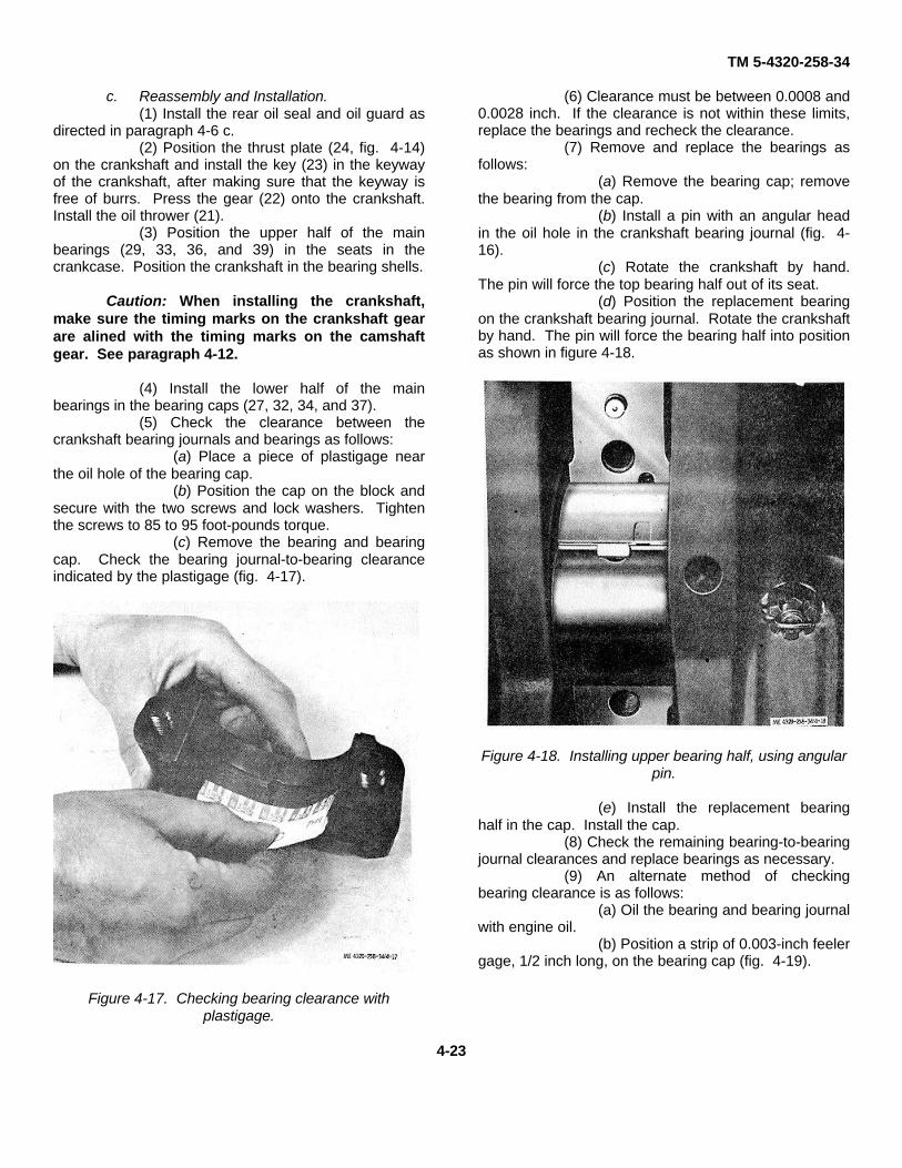
TM 5-4320-258-34
c. Reassembly and Installation.(1) Install the rear oil seal and oil guard as
directed in paragraph 4-6 c.(2) Position the thrust plate (24, fig. 4-14)
on the crankshaft and install the key (23) in the keywayof the crankshaft, after making sure that the keyway isfree of burrs. Press the gear (22) onto the crankshaft.Install the oil thrower (21).
(3) Position the upper half of the mainbearings (29, 33, 36, and 39) in the seats in thecrankcase. Position the crankshaft in the bearing shells.
Caution: When installing the crankshaft,make sure the timing marks on the crankshaft gearare alined with the timing marks on the camshaftgear. See paragraph 4-12.
(4) Install the lower half of the mainbearings in the bearing caps (27, 32, 34, and 37).
(5) Check the clearance between thecrankshaft bearing journals and bearings as follows:
(a) Place a piece of plastigage nearthe oil hole of the bearing cap.
(b) Position the cap on the block andsecure with the two screws and lock washers. Tightenthe screws to 85 to 95 foot-pounds torque.
(c) Remove the bearing and bearingcap. Check the bearing journal-to-bearing clearanceindicated by the plastigage (fig. 4-17).
Figure 4-17. Checking bearing clearance withplastigage.
(6) Clearance must be between 0.0008 and0.0028 inch. If the clearance is not within these limits,replace the bearings and recheck the clearance.
(7) Remove and replace the bearings asfollows:
(a) Remove the bearing cap; removethe bearing from the cap.
(b) Install a pin with an angular headin the oil hole in the crankshaft bearing journal (fig. 4-16).
(c) Rotate the crankshaft by hand.The pin will force the top bearing half out of its seat.
(d) Position the replacement bearingon the crankshaft bearing journal. Rotate the crankshaftby hand. The pin will force the bearing half into positionas shown in figure 4-18.
Figure 4-18. Installing upper bearing half, using angularpin.
(e) Install the replacement bearinghalf in the cap. Install the cap.
(8) Check the remaining bearing-to-bearingjournal clearances and replace bearings as necessary.
(9) An alternate method of checkingbearing clearance is as follows:
(a) Oil the bearing and bearing journalwith engine oil.
(b) Position a strip of 0.003-inch feelergage, 1/2 inch long, on the bearing cap (fig. 4-19).
4-23

TM 5-4320-258-34
Figure 4-19. Checking bearing clearance with shimstock.
(c) Install the cap on the block; securewith the screws and lock washers. Tighten the screws to85 to 95 foot-pounds torque.
(d) Try to turn the crankshaft by hand.If the crankshaft will not turn or a very definite drag isfelt, bearing-to-bearing journal clearance is withintolerance. Remove the shim stock and reinstall thebearing caps.
(10) After all main bearings have beeninstalled, use a dial indicator to check crankshaft endplay. If end play is not between 0.003 and 0.008 inch,replace the thrust plate (24) which controls the shaft endplay..
(11) Install the pistons and connecting rods(para 4-10c).
(12) Install the flywheel housing andflywheel (para 4-9c).
(13) Install the gear cover (para 4-8c).(14) Install the oil pan (para 4-6c) and oil
pump (para 4-7c).(15) Install the cylinder head (para 4-3c).
4-12. Camshafta. Removal. With the engine removed from
the pump assembly and mounted on an engine stand,proceed as follows:
(1) Remove the cylinder head (para 4-3a).(2) Remove the valves and valve tappets
(para 4-4b).(3) Remove the gear cover (para 4-8a).(4) Remove the nut (14, fig. 4-3) from the
camshaft (20) and pull the gear (15) from the cam shaft.(5) Remove the two cap screws (17) and
lock washers (18) that secure the thrust plate (19) to theblock; remove the thrust plate.
(6) Pull the camshaft (20) from the block.
b. Cleaning and Inspection.(1) Clean all parts with cleaning solvent
(FED. Spec. P-D-680); dry thoroughly.(2) Inspect the camshaft for cracks, worn or
scored cams worn or scored bearing surfaces, chipped,cracked, or broken gear teeth, and clogged oilpassages. Refer to table 4-1 for wear limits.Replace a damaged camshaft.
(3) Inspect the thrust washer for scoringand wear. Replace the thrust washer if any signs ofwear are evident.
(4) Inspect the cam gear for cracked,chipped, or broken gear teeth, damaged shaft bore, orworn thrust surface. The cam gear and the mating gearon the crankshaft must be replaced as a pair. Do notattempt to replace these gears singly.
(5) Inspect the plug (33, fig. 4-22) in thecylinder block. Replace if any leaking is evident fromthe circumference of the plug.
(6) Inspect the camshaft bearings in thecylinder block for scoring or visible damage; replacedamaged bearings if necessary. Check the camshaft-to-bearing clearance and, if necessary, replace bearings asfollows:
Caution: Do not insert the camshaft too farinto the block. If the camshaft bumps theexpansion plug on the drive end of the engine, anoil leak could result.
(a) Temporarily insert the camshaft(20, fig. 4-3) in the block. Check the clearance betweenthe camshaft bearing journals and camshaft bearings(21, 22, 23, and 24) with feeler stock cut in strips 1/4inch wide. Dress the feeler stock with a stone toeliminate burrs or feathered edges. Clearance betweenbearings and journals must be between 0.002 and 0.004inch.
(b) If clearance exceeds tolerances,remove the camshaft and remove the camshaftbearings. New bearings are pre-reamed. Install newbearings, taking care to aline the oil holes with thepassages in the block. Use caution to prevent damageto the bearings during installation.
c. Installation.(1) Lubricate the camshaft bearings with
engine oil and install the camshaft in the block. Positionthe thrust plate (19, fig. 4-3) on the camshaft; securewith two cap screws (17) and lock washers (18).
Caution: When installing the camshaft gear,do not attempt to seat the gear by tightening theretaining nut. This may break threads on thecamshaft, requiring camshaft replacement.
(2) Hold the camshaft toward the front ofthe engine with a bar inserted into the fuel pump hole.Aline the timing marks on the camshaft and crankshaftgears (fig. 4-20) and drive the gear (15, fig. 4-3) ontothe camshaft.
4-24
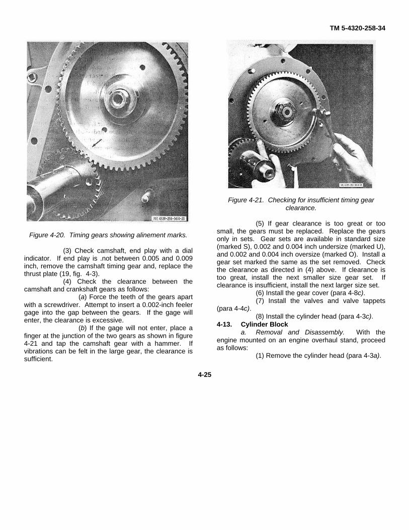
TM 5-4320-258-34
Figure 4-20. Timing gears showing alinement marks.
(3) Check camshaft, end play with a dialindicator. If end play is .not between 0.005 and 0.009inch, remove the camshaft timing gear and, replace thethrust plate (19, fig. 4-3).
(4) Check the clearance between thecamshaft and crankshaft gears as follows:
(a) Force the teeth of the gears apartwith a screwdriver. Attempt to insert a 0.002-inch feelergage into the gap between the gears. If the gage willenter, the clearance is excessive.
(b) If the gage will not enter, place afinger at the junction of the two gears as shown in figure4-21 and tap the camshaft gear with a hammer. Ifvibrations can be felt in the large gear, the clearance issufficient.
Figure 4-21. Checking for insufficient timing gearclearance.
(5) If gear clearance is too great or toosmall, the gears must be replaced. Replace the gearsonly in sets. Gear sets are available in standard size(marked S), 0.002 and 0.004 inch undersize (marked U),and 0.002 and 0.004 inch oversize (marked O). Install agear set marked the same as the set removed. Checkthe clearance as directed in (4) above. If clearance istoo great, install the next smaller size gear set. Ifclearance is insufficient, install the next larger size set.
(6) Install the gear cover (para 4-8c).(7) Install the valves and valve tappets
(para 4-4c).(8) Install the cylinder head (para 4-3c).
4-13. Cylinder Blocka. Removal and Disassembly. With the
engine mounted on an engine overhaul stand, proceedas follows:
(1) Remove the cylinder head (para 4-3a).
4-25

TM 5-4320-258-34
(2) Remove the intake and exhaust valves(para 4-4b) and intake and exhaust manifolds (para 4-5a).
(3) Remove the oil pan (para 4-6a) and oilpump (para 4-7a).
(4) Remove the gear cover (para 4-8a).(5) Remove the flywheel and flywheel
housing (para 4-9a).(6) Remove the pistons and connecting
rods (para 4-10a).
(7) Remove the crankshaft and mainbearings (para 4-11a).
(8) Remove the camshaft (para 4-12a).(9) Remove the assembled washer screw
(19, fig. 4-9), cap screws (20), and flat washers (21)that secure the front end plate (22) to the cylinder block;remove the backing plate and gasket (23).
(10) Remove the plug (33, fig. 4-22) andgasket (24); remove the spring (25), washers (26), andoil pressure relief valve (27).
4-26

TM 5-4320-258-34
Figure 4-22. Cylinder block and flywheel housing, exploded view.
4-27

TM 5-4320-258-34
KEY to fig. 4-22:
1. Oil gage rod2. Oil gage rod support3. Oil filler cap4. Oil filler nipple5. Nut6. Gasket7. Valve chamber cover8. Gasket9. Stud
10. Stud11. Cap screw12. Lock washer13. Shoulder screw14. Lock washer15. Flywheel housing16. Screw17. Timing hole cover18. Felt19. Drive screw pointer20. Housing plug21. Lock washer22. Ring dowel23. Plug24. Gasket25. Relief valve spring26. Pressure adjusting washer27. Oil pressure relief valve28. Ring dowel29. Ring dowel30. Oil header plug31. Core hole plug32. Core hole plug33. Core hole plug34. Baffle35. Cylinder block
b. Cleaning.(1) Remove dirt and grease deposits from
the block with a putty knife. Steam-clean the block.Remove greasy or gummy deposits with a clothdampened in cleaning solvent (FED. Spec. P-D-680).Clean the oil and water passages in the block withcompressed air. Remove varnish deposits with a wirebrush.
(2) Clean the mounting plate and all otherparts with cleaning solvent (FED. Spec. P-D-680); drythoroughly.
c. Inspection.(1) Inspect the block for cracks, damaged
sealing surfaces, scored or damaged bearing seats,scored or scratched cylinder walls, damaged threads,loose or damaged studs, corrosion in the water jacket, orother defects.
(2) Check piston fit in the cylinder bores(para 4-10c).
(3) Check cylinder bore wear with an insidemicrometer. Measure the cylinder bore at 45° intervalsbelow the travel of the lowest piston ring where thecylinder is not worn. Compare this measurement with ameasurement taken about 1/4 inch below the top of thecylinder. The maximum allowable cylinder wear (thedifference between these two measurements),is 0.008inch.
(4) Replace the block if, it is cracked, or ifdefects cannot be repaired. Replace loose or damagedstuds. Retap damaged threads. If a proper piston fitcannot be attained, (para 4-10 c), the cylinders arescratched or scored, or, cylinder wear exceeds 0.008inch, rebore the cylinders as directed in d below.
(5) Inspect the backing plate for cracks anddistortion. Remove any burrs with a fine stone.
(6) Inspect the oil pressure relief valve forscoring, wear, and other damage. Inspect the spring forcracks and misalined coils. Replace damaged oilpressure regulator parts.
d. Reboring. Rebore the cylinders to 3.4575-to 3.4595-inch diameter (0.020 inch oversize). If this isnot sufficient to eliminate cylinder wear or damage,rebore the cylinders to 3.4775- to 3.4795-inch diameter(0.040 inch oversize). Maximum allowable overbore is0.040 inch.
e. Reassembly and Installation.(1) Reassembly and installation is the
reverse of removal and disassembly. Refer to figure 4-22.
(2) When installing the front end plate (22,fig. 4-9), tighten the 5/16-inch bolts to 15 to 20 foot-pounds torque and tighten the 3 / 8-inch bolts to 25 to 30foot-pounds torque.
(3) Install the camshaft (para 4-12c).(4) Install the crankshaft and main bearings
(para 4-11c).(5) Install the pistons and connecting rods
(para 4-10c).(6) Install the flywheel and flywheel
housing (para 4-9c).(7) Install the gear cover (para 4-8c).(8) Install the oil pump (para 4-7c) and oil
pan (para 4-6c).(9) Install the intake and exhaust valves
(para 4-4 d), and intake and exhaust manifolds (para45c).
(10) Install the cylinder head (para 4-3c).(11) See paragraph 3-13 for oil pressure
adjustment procedure.
4-28

TM 5-4320-258-34
CHAPTER 5
REPAIR OF CENTRIFUGAL PUMP
5-1. GeneralThis chapter covers repair and overhaul of thecentrifugal pump. Repair includes seal replacement andcheck valve replacement. Overhaul consists ofcomplete teardown to allow inspection and, if necessary,replacement of all operating parts, including bearings,impeller, and wear plate. Repair can be done withoutremoval of the entire pump assembly from the engine
and skid. Overhaul requires removal of the unit to aworkbench.
5-2. Check Valve ReplacementReplace the check valve as follows:
a. Remove the nuts (6, fig. 5-1) that securethe suction flange (7) to the pump body; remove thesuction flange and gasket (8).
5-1

TM 5-4320-258-34
Figure 5-1. Suction and discharge assemblies, exploded view.
5-2

TM 5-4320-258-34
b. Remove the check valve seat (9) and thecheck valve assembly consisting of the large weight(13), small weight (14), and gasket (15). Remove thescrew (10), nut (11), and lock washer (12) to separatethe check valve parts.
c. Clean all parts with cleaning solvent (FED.Spec. P-D-680); dry thoroughly.
d. Inspect the gasket for wear, cracks, tears,and damaged seating surfaces. Replace a damagedgasket.
e. Inspect the check valve seat for cracks andfor a damaged seating surface. Replace if damaged.
f. Reassemble the parts by reversing theremoval procedure. Make sure the small weight isassembled to face outward. Tighten the nuts evenlyand alternately in increments to prevent distortion of thecheck valve gasket.
g. After assembly, operate the check valve byhand to assure that it operates freely, and that it seatsfirmly against the valve seat.
5-3. Shaft Seal Replacement Replacea. leaking shaft seal as follows: a. Remove
the tool box from the centrifugal pump assembly (TM 5-4320-258-12).
b. Remove the drain plug (1, fig. 5-1) anddrain all fluid from the pump body.
c. Use a hoist or other lifting device tosupport the weight of the pump body (3, fig. 5-2).Remove the bolts, nuts, and lock washers that securethe feet of the pump body to the skid base.
5-3
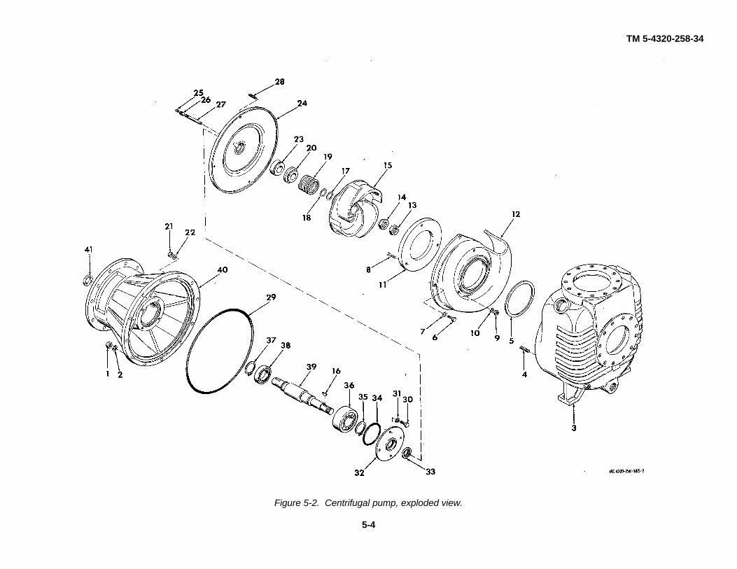
TM 5-4320-258-34
Figure 5-2. Centrifugal pump, exploded view.
5-4

TM 5-4320-258-34
KEY to fig. 5-2:1. Nut2. Lock washer3. Pump body4. Stud5. Volute gasket6. Cap screw7. Lock washer8. Flat head screw9. Nut
10. Lock washer11. Wear plate12. Volute13. Lock nut14. Impeller nut15. Impeller16. Woodruff key17. Shim18. Shim19. Seal spring20. Seal rotating member21. Nut22. Lock washer23. Seal stationary member24. Seal plate25. Pipe plug26. Coupling27. Pipe nipple28. Stud29. Preformed packing30. Cap screw31. Lock washer32. Bearing cap33. Grease seal34. Preformed packing35. Retaining ring36. Ball bearing37. Retaining ring38. Ball bearing39. Impeller shaft40. Bearing housing41. Grease seal
d. Remove the nuts (1) and lock washers (2) thatsecure the pump body (3) to the bearing housing (40); slidethe pump body straight out to disengage it from the remainderof the pump which is secured to the engine.
e. Remove the cap screws (6) and lock washers(7) that secure the assembled volute (12) and wear plate (11)to the seal plate (24); remove the assembled parts.
f. Remove the nuts (13 and 14) that secure theimpeller (15) to the impeller shaft (39). Pull the impeller fromthe shaft and remove the key (16). Remove the shims (17and 18), seal spring (19), and seal rotating member (20) fromthe shaft.
g. Remove the nuts (21) and lock washers (22)that secure the seal plate (24) to the bearing housing (40);remove the seal plate with the assembled seal stationary
member (23). Remove the seal stationary member from theseal plate.
Note: The seal members are not replaceableindividually. When replacing the seal, be sure to replace allparts that are provided in the seal kit.
h. Install the seal stationary member (23) in theseal plate (24); install the seal plate on the bearing housing(40) with nuts (21) and lock washers (22).
i. Lubricate the inside diameter of the sealrotating member (20). Install the rotating member on theshaft, and install the seal spring (19). Take care to preventdamage to the interior of the seal member during assembly orpremature failure will result. Also use extreme care to preventdamage to the contact faces, both the stationary and rotatingseal members.
j. When installing the impeller (15), be sure toinstall the same thickness of shims (17 and 18) that wasremoved.
k. Reassemble the remainder of the pump byreversing the disassembly procedure.5-4. Centrifugal Pump Overhaul
a. Disassembly. Remove the pump from theengine and skid (TM 5-4320-258-12). Disassemble in thesequence indicated in figures 5-1 and 5-2. Note the following:
(1) Press the impeller shaft (39, fig. 5-2) andbearings (36 and 38) from the bearing housing (40) as anassembly.
(2) Remove the retaining rings (35 and 37) andpress the ball bearings (36 and 38) from-the shaft.
b. Cleaning and Inspection.(1) Discard and replace all seals, gaskets, and
packings.(2) Clean the ball bearings as directed in
paragraph 2-7.(3) Clean all remaining parts with cleaning
solvent (FED. Spec. P-D-680); wipe dry.(4) Inspect the check valve seat for cracks,
chipped edges, and other damage; replace a damaged checkvalve seat.
(5) Inspect the suction flange and dischargeelbow for distortion, cracks, and damaged connector grooves.Remove nicks and burrs from the connector grooves with afine stone. Replace if damaged beyond repair.
(6) Inspect the pump body for cracks, loose ordamaged studs, and for damaged threads. Clean updamaged threads with a thread die. Replace any damagedstuds. Replace the housing if worn beyond repair.
(7) Inspect the wear plate for damage or wear.If the wear is perceptible, replace the plate.
(8) Inspect the volute for cracks, distortion, andwear. Replace if damaged.
(9) Inspect the impeller for cracked, chipped,worn or broken vanes, damaged or distorted bore or keyway,and other damage; replace a damaged impeller.
(10) Inspect the ball bearings for scored balls orraces, cracked races, signs of overheating, or
5-5

TM 5-4320-258-34
rough, catching, or binding operation; replace damagedbearings.
(11) Inspect the impeller shaft for distortionand damaged retaining ring grooves, keyways, andthreads. Clean up damaged retaining ring grooves orkeyways with a fine stone. Repair damaged threadswith a thread chaser. Replace the shaft if it is damagedbeyond repair.
(12) Inspect the bearing housing for cracks,distortion, or scored or burred bearing seats. Removenicks or burrs from the bearing seats with a fine stone.Clean up damaged threads with a thread die. Replace adamaged bearing housing.
c. Reassembly. Reassemble the pump byreversing the disassembly sequence. Refer to figures 5-1 and 5-2. Note the following:
(1) Press bearings (36 and 38, fig. 5-2)onto the impeller shaft (39). If bearings slide onto theshaft by hand, they are too loose and the bearings and /or shaft must be replaced. Secure bearings to the shaftwith retaining rings (35 and 37).
(2) Pack the bearings, bearing cap, and thearea between the bearings in the bearing housing withMIL-G-10924 grease.
(3) Press grease seal (41) into the bearinghousing (40) and grease seal (33) into the bearing cap(32) before installing the shaft and bearings in thebearing housing.
(4) Press the seal stationary member (23)into seal plate (24) before installing the plate. Lubricate
the shaft lightly with oil and slide the seal rotatingmember (20) in place on the shaft.
(5) If the same impeller (15) and wear plate(11) are reassembled and no clearance change isindicated, make sure that the same thickness of shims '(17 and 18) is used. If a new impeller and / or wearplate is to be installed, or if the impeller clearance is tobe changed, determine the shim thickness required toobtain a clearance of 0.010 to 0.020 inch between theimpeller and wear plate as follows:
(a) Install impeller (15) on shaft (39)without shims. Be sure that it is seated firmly againstthe shaft shoulder.
(b) Install volute (12), with wear plate( 11 ) assembled, and secure with screws (6) and lockwashers (7).
(c) Measure from the face of theimpeller (15) to the face of the wear plate ( 11) using afeeler gage.
(d) Select shims (17 and 18) to equalthe dimension obtained less 0.010 to 0.020 inch forclearance.
(6) After assembly, check the impellershaft for free rotation. It must turn freely withoutcatching or binding. If binding is evident, disassembleand correct the condition upon reassembly.
(7) Install the pump on the engine and skid(TM 5-4320-258-12).
5-6

TM 5-4320-258-34
APPENDIX A
REFERENCES
A-1. Fire ProtectionTB 5-4200-200-10 Hand Portable Fire Extinguishers Approved for
Army UsersA-2. Lubrication
C9100-IL Identification List for Fuels, Lubricants, Oils andWaxes
LO 5-4320-258-12 Lubrication Order for Pump, Centrifugal, BarnesModel US67CCG
A-3. PaintingTM 9-213 Painting Instructions for Field Use
A-4. Radio SuppressionTM 11-483 Radio Interference Suppression
A-5. MaintenanceFed. Spec. P-D-680 Dry Cleaning Metal PartsTB 750-651 Use of Antifreeze Solutions and Cleaning Com-
pounds in Engine Cooling SystemsTM 38-750 The Army Maintenance Management SystemTM 4320-258-34 DS, GS, and Depot Maintenance Manual for
Pump, Centrifugal, Barnes Model US67CCGTM 5-4320-258-20P Organizational Maintenance Repair Parts Manual
for Pump, Centrifugal, Barnes Model US67CCGTM 5-4320-258-34P DS, GS, and Depot Maintenance Repair Parts List
for Pump, Centrifugal, Barnres Model US67CCGTM 9-6140-200-15 Operation and Organizational Field and Depot
Maintenance Storage Batteries, Lead Acid TypeTM 5-764 Electric Motor and Generator RepairTM 5-4320-258-12 Operator and Organizational Maintenance Manual
for Pump, Centrifugal, Barnes Model US67CCG
A-6. Shipment and StorageTB 740-93-2 Preservation of USAMEC Mechanical Equipment
for Shipment and StorageTM 740-90-1 Administrative Storage of Equipment
A-7. Destruction of Army Materiel to PreventEnemy UseTM 750-244-3 Procedures for Destruction of Equipment to
Prevent Enemy Use (Mobility EquipmentCommand)
A-1

TM 5-4320-258-34
By Order of the Secretary of the Army:
W. C. WESTMORELAND,General, United States Army,
Official: Chief of Staff.
VERNE L. BOWERS,Major General, United States Army,The Adjutant General.
Distribution:
To be distributed in accordance with DA Form 12-25 (qty rqr Block No. 155), Direct/ General Support requirements forPetroleum Distribution.
* U.S. GOVERNMENT PRINTING OFFICE: 1971-769-158/83


PIN: 008489-000

This fine document...
Was brought to you by me:
Liberated Manuals -- free army and government manuals
Why do I do it? I am tired of sleazy CD-ROM sellers, who take publicly available information, slap “watermarks” and other junk on it, and sell it. Those masters of search engine manipulation make sure that their sites that sell free information, come up first in search engines. They did not create it... They did not even scan it... Why should they get your money? Why are not letting you give those free manuals to your friends?
I am setting this document FREE. This document was made by the US Government and is NOT protected by Copyright. Feel free to share, republish, sell and so on.
I am not asking you for donations, fees or handouts. If you can, please provide a link to liberatedmanuals.com, so that free manuals come up first in search engines:
<A HREF=http://www.liberatedmanuals.com/>Free Military and Government Manuals</A>
– SincerelyIgor Chudovhttp://igor.chudov.com/
– Chicago Machinery Movers