Department of Roads
162
Government of Nepal Ministry of Physical Infrastructure and Transport Department of Roads Maintenance Branch Manual for Dense Graded Bituminous Mixes (DBM/BC) (Final) 2018
Transcript of Department of Roads

Government of Nepal
Ministry of Physical Infrastructure and Transport
Department of Roads
Maintenance Branch
Manual for Dense Graded Bituminous Mixes (DBM/BC) (Final)
2018
Forward
Several major construction factors directly affect the ultimate performance of an HMA
pavement; the structural design of the pavement layers; the asphalt-aggregate mix design; the
construction procedures used to produce, place, and compact the mix; and the workmanship or
quality of construction. Poor workmanship can be one of the most significant factors leading to
premature distress of an asphalt pavement.
Highway construction specifications are a means to an end. Their objective is to provide the
traveling public with an adequate and economical pavement on which vehicles can move easily
and safely from point to point. A practical specification is one that is designed to ensure
adequate performance at minimum cost; a realistic specification takes account of variations in
materials and construction that are inevitable and characteristic of the best construction
possible today.
The HMA plant is one of the major component in the process of achieving quality DBM/AC.
The aggregate used can be a single material, such as a crusher run aggregate, or it can be a
combination of coarse and fine aggregates, with mineral filler. The binder material used is
normally asphalt cement but may be an asphalt emulsion or one of a variety of modified
materials. There are two basic types of HMA plants currently in use in the Nepal: batch and
parallel-flow drum-mix. All two types serve the same ultimate purpose, and the asphalt
mixture should be essentially similar regardless of the type of plant used to manufacture it.
Therefore, “Manual for Dense Graded Bituminous Mixes (DBM/BC)” has been approved and
has been recommended to follow, to address these issues/scenarios. The contribution of Er.
Prabhat Kumar Jha, Senior Divisional Engineer and; suggestions and experience shared by
peer review team for finalization of the manual; is highly appreciated.
I hope the manual will lead the Department of Roads to achieve higher level of quality for
Asphalt concrete pavement.
Thank You
……………………
Er. Rabindra Nath Shrestha Director General Department of Roads
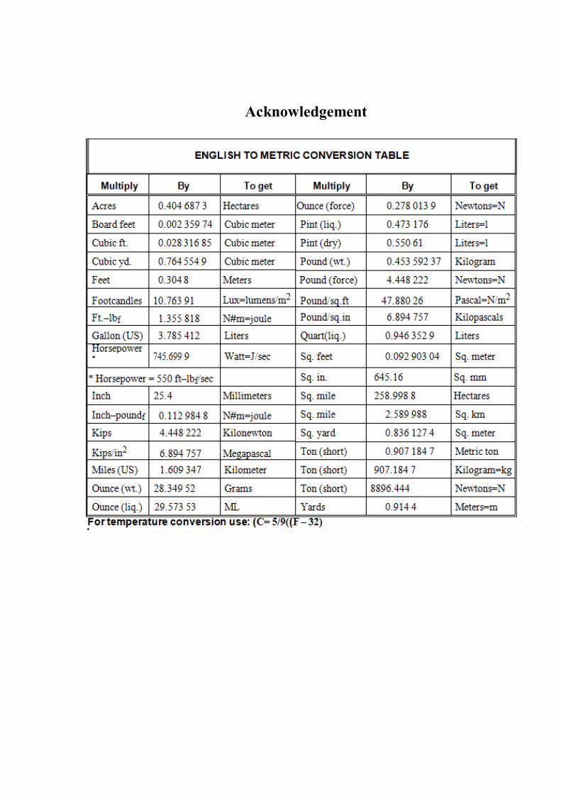
Acknowledgement
The Manual for Dense Graded Bituminous Mixes (DBM/BC) has been prepared with reference
to Standard Specifications for Road and Bridge Works,2073 of DOR,MS-2 Asphalt Mix
Design Methods, 7th Edition,IRC 111-2009, Specification for Dense Graded Bituminous
Mixes, Hot-Mix Asphalt Paving Handbook, Part I-III, US Army Corps of Engineers, HOT
MIX ASPHALT (HMA) TECHNICIAN TRAINING MANUAL, FHWA Multi-Regional
Asphalt Training and Certification Group, 1999, and relevant IS/IRC Codes.
The Manual has covered the Flow Chart for DBM/AC Application, Material Selection,
Marshall Method of HMA Mix Design, Hot-Mix Asphalt Plant Operations, Field Operation,
Field Verification of Bituminous Mixtures, Bailey Method, Best Practices of HMA. It is
believed that the Manual will boost the quality management during the construction of
DBM/AC pavement under DOR.
The effort and dedication of Er.Prabhat Kumar Jha,(SDE); is highly appreciable. The support
of review team members Er. Shiv Raj Adhakari(SDE), Er. Binod Sapkota (SDE), Er. Narayan
Pd. Lamichhane, & Er. Rajib Shrestha, is also acknowledged by the department.
And, also the department is grateful to Road Board Nepal for kind funding support for the
manual preparation.
……………………
Er. Shiv Prasad Nepal Deputy Director General Maintenance Branch Department of Roads
Acknowledgement
Acknowledgement
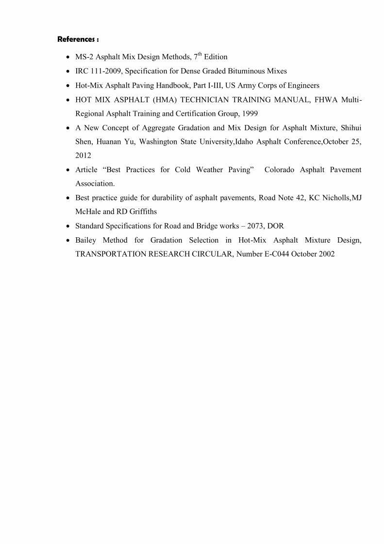
References :
MS-2 Asphalt Mix Design Methods, 7th Edition
IRC 111-2009, Specification for Dense Graded Bituminous Mixes
Hot-Mix Asphalt Paving Handbook, Part I-III, US Army Corps of Engineers
HOT MIX ASPHALT (HMA) TECHNICIAN TRAINING MANUAL, FHWA Multi-
Regional Asphalt Training and Certification Group, 1999
A New Concept of Aggregate Gradation and Mix Design for Asphalt Mixture, Shihui
Shen, Huanan Yu, Washington State University,Idaho Asphalt Conference,October 25,
2012
Article “Best Practices for Cold Weather Paving” Colorado Asphalt Pavement
Association.
Best practice guide for durability of asphalt pavements, Road Note 42, KC Nicholls,MJ
McHale and RD Griffiths
Standard Specifications for Road and Bridge works – 2073, DOR
Bailey Method for Gradation Selection in Hot-Mix Asphalt Mixture Design,
TRANSPORTATION RESEARCH CIRCULAR, Number E-C044 October 2002

Chapter 1 Introductory
Manual for Dense Graded Bituminous Mixes (DBM/BC)
C1:
C1.1 Dense-Graded Bituminous Mixes
A dense-graded mix is a well-graded HMA mixture intended for general use. When properly designed and constructed, a dense-graded mix is relatively impermeable. Dense-graded mixes are generally referred to by their nominal maximum aggregate size. They can further be classified as either fine-graded or coarse-graded. Fine-graded mixes have more fine and sand sized particles than coarse-graded mixes (Table 1.1 for definitions of fine- and coarse-graded mixes).
Dense-graded mixes are suitable for all pavement layers and for all traffic conditions. They work well for structural, friction, leveling and patching needs.
Table 1.1 Fine- and Coarse-Graded Definitions for Dense-Graded HMA (.Re NAPA_USA, 2001)
Mixture Nominal Maximum
Aggregate Size # Coarse-Graded Mix Fine-Graded Mix
35.5 mm < 35 % passing the 4.75 mm (No. 4 Sieve)
> 35 % passing the 4.75 mm (No. 4 Sieve)
26.5 mm < 40 % passing the 4.75 mm (No. 4 Sieve)
> 40 % passing the 4.75 mm (No. 4 Sieve)
19.0 mm < 35 % passing the 2.36 mm (No. 8 Sieve)
> 35 % passing the 2.36 mm (No. 8 Sieve)
13.2 mm < 40 % passing the 2.36 mm (No. 8 Sieve)
>40 % passing the 2.36 mm (No. 8 Sieve)
Pictorial Example
# The nominal maximum aggregate size is one size larger than the first sieve to retain more than 10 percent of the material. Maximum aggregate size (MAS) is one size larger than nominal maximum’s size. It is important to understand that the “nominal” top size aggregate does not refer to the maximum size of the aggregate in the mix, but to the sieve that retains 10 percent of the aggregate. Therefore a 19.0 mm nominal size mix could contain 10 percent of the aggregate larger than the 19.0 mm sieve.
Maximum Density Line
Chapter 1 Introductory
Manual for Dense Graded Bituminous Mixes (DBM/BC)
C1:
HMA consists of two basic ingredients: aggregate and asphalt binder. HMA mix design is the process of determining what aggregate to use, what asphalt binder to use and what the optimum combination of these two ingredients ought to be.
By manipulating the variables of aggregate, asphalt binder and the ratio between the two, mix design seeks to achieve the following qualities in the final HMA product (Roberts et al., 1996):
Deformation resistance: HMA should not distort (rut) or deform (shove) under traffic loading. HMA deformation is related to aggregate surface and abrasion characteristics, aggregate gradation, asphalt binder content and asphalt binder viscosity at high temperatures.
Fatigue resistance: HMA should not crack when subjected to repeated loads over time. HMA fatigue cracking is related to asphalt binder content and stiffness.
Low temperature cracking resistance: HMA should not crack when subjected to low ambient temperatures. Low temperature cracking is primarily a function of the asphalt binder low temperature stiffness.
Durability: HMA should not age excessively during production and service life. HMA durability is related to air voids as well as the asphalt binder film thickness around each aggregate particle.
Moisture damage resistance: HMA should not degrade substantially from moisture penetration into the mix. Moisture damage resistance is related to air voids as well as aggregate mineral and chemical properties.
Skid resistance: HMA placed as a surface course should provide sufficient friction when in contact with a vehicle's tire. Low skid resistance is generally related to aggregate characteristics or high asphalt binder content.
Workability: HMA must be capable of being placed and compacted with reasonable effort. Workability is generally related to aggregate texture/shape/size/gradation, asphalt binder content and asphalt binder viscosity at mixing and placement temperatures.
C1.2 Aggregate Packing
Aggregate particles cannot be packed together to fill a volume completely. There will always be space between the aggregate particles. The degree of packing depends on:
• Type and amount of compactive energy. Several types of compactive force can be used, including static pressure, impact (e.g., Marshall hammer), or shearing (e.g., gyratory shear compactor or California kneading compactor). Higher density can be achieved by increasing the compactive effort (i.e., higher static pressure, more blows of the hammer, or more tamps or gyrations).
• Shape of the particles. Flat and elongated particles tend to resist packing in a dense configuration. Cubical particles tend to arrange in dense configurations.
• Surface texture of the particles. Particles with smooth textures will re-orient more easily into denser configurations. Particles with rough surfaces will resist sliding against one another.
• Size distribution (gradation) of the particles. Single-sized particles will not pack as densely as a mixture of particle sizes.
• Strength of the particles. Strength of the aggregate particles directly affects the amount of degradation that occurs in a compactor or under rollers. Softer aggregates typically degrade more than strong aggregates and allow denser aggregate packing to be achieved.
The properties listed above can be used to characterize both coarse and fine aggregates. The individual characteristics of a given aggregate, along with the amount used in the blend, has a direct impact on the resulting mix properties. When comparing different sources of comparably sized aggregates, the designer should consider these individual characteristics. Even though an aggregate may have acceptable characteristics, it may not combine well with the other proposed aggregates for use in the design. The final combination of coarse and fine aggregates, and their corresponding individual properties, determines the packing characteristics of the overall blend for a given type and amount of compaction. Therefore, aggregate source selection is an important part of the asphalt mix design process.

Chapter 1 Introductory
Manual for Dense Graded Bituminous Mixes (DBM/BC)
C1:
C1.3 Defining Coarse and Fine Aggregate
The traditional definition of coarse aggregate is any particle that is retained by the 4.75-sieve. Fine aggregate is defined as any aggregate that passes the 4.75-mm sieve (sand, silt, and clay size material). The same sieve is used for 13.2-mm mixtures as 26.5-mm mixtures.
According to the Bailey Method, the definition of coarse and fine is more specific in order to determine the packing and aggregate interlock provided by the combination of aggregates in various sized mixtures. The Bailey Method definitions are:
• Coarse Aggregate: Large aggregate particles that when placed in a unit volume create voids.
• Fine Aggregate: Aggregate particles that can fill the voids created by the coarse aggregate in the mixture.
From these definitions, more than a single aggregate size is needed to define coarse or fine. The definition of coarse and fine depends on the nominal maximum aggregate size (NMAS) of the mixture. In a dense-graded blend of aggregate with a NMAS of 37.5 mm, the 37.5- mm particles come together to make voids. Those voids are large enough to be filled with 9.5-aggregate particles, making the 9.5-mm particles fine aggregate. Now consider a typical surface mix with a NMPS of 9.5 mm. In this blend of aggregates, the 9.5-mm particles are considered coarse aggregate. In the Bailey Method, the sieve which defines coarse and fine aggregate is known as the primary control sieve (PCS), and the PCS is based on the NMPS of the aggregate blend.The PCS is defined as the closest sized sieve to the result of the PCS formula.
PCS for the overall blend = NMAS × 0.22
It is important to remember that the fine aggregate is small enough to fit into the void spaces created by material retained on the PCS. The interesting thing to keep in mind is that the largest fine particles also create void spaces that smaller fine aggregate particles occupy. The critical size of the fine fraction is defined as 0.22 × PCS which creates a Secondary Control Sieve (SCS).
SCS for the overall blend = PCS × 0.22
The fine sand is further evaluated by determining the Tertiary Control Sieve (TCS), which is determined by multiplying the SCS by the 0.22 factor
Table 1.2 PSC SCS & TCS for various NMAS
NMAS,mm For Coarse-Graded Mix For Fine-Graded Mix
Half Sieve,mm
PCS,mm
SCS,mm
TCS,mm
Half Sieve,mm
PCS,mm
SCS,mm
TCS,mm
35.5 19.0 4.75 2.36 0.60 4.75 2.36 0.60 0.15
26.5 13.2 4.75 1.18 0.30 2.36 1.18 0.30 0.075 19 9.5 4.75 1.18 0.30 2.36 1.18 0.30 0.075
13.2 4.75 2.36 0.6 0.15 1.18 0.60 0.150 -
C1.4 Loose and Rodded Unit Weight of Coarse Aggregate
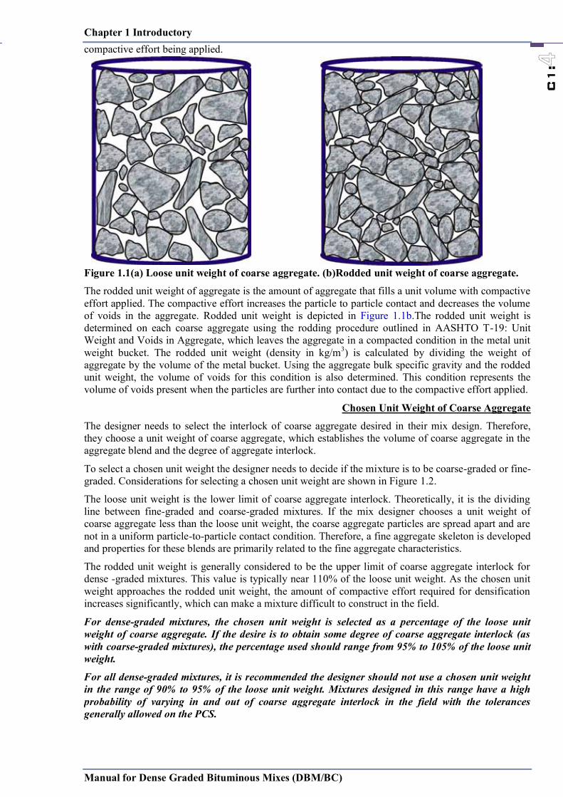
The loose unit weight of an aggregate is the amount of aggregate that fills a unit volume without any compactive effort applied. This condition represents the beginning of coarse aggregate interlock (i.e., particle-to-particle contact) without any compactive effort applied. The loose unit weight is depicted in Figure 1.1a).
The loose unit weight is determined on each coarse aggregate using the shoveling procedure outlined in AASHTO T-19: Unit Weight and Voids in Aggregate, which leaves the aggregate in a loose ondition in the metal unit weight bucket. The loose unit weight (density in kg/m3) is calculated by dividing the weight of aggregate by the volume of the metal bucket. Using the aggregate bulk specific gravity and the loose unit weight, the volume of voids for this condition is also determined. This condition represents the volume of voids present when the particles are just into contact without any outside
Chapter 1 Introductory
Manual for Dense Graded Bituminous Mixes (DBM/BC)
C1:
C1.3 Defining Coarse and Fine Aggregate
The traditional definition of coarse aggregate is any particle that is retained by the 4.75-sieve. Fine aggregate is defined as any aggregate that passes the 4.75-mm sieve (sand, silt, and clay size material). The same sieve is used for 13.2-mm mixtures as 26.5-mm mixtures.
According to the Bailey Method, the definition of coarse and fine is more specific in order to determine the packing and aggregate interlock provided by the combination of aggregates in various sized mixtures. The Bailey Method definitions are:
• Coarse Aggregate: Large aggregate particles that when placed in a unit volume create voids.
• Fine Aggregate: Aggregate particles that can fill the voids created by the coarse aggregate in the mixture.
From these definitions, more than a single aggregate size is needed to define coarse or fine. The definition of coarse and fine depends on the nominal maximum aggregate size (NMAS) of the mixture. In a dense-graded blend of aggregate with a NMAS of 37.5 mm, the 37.5- mm particles come together to make voids. Those voids are large enough to be filled with 9.5-aggregate particles, making the 9.5-mm particles fine aggregate. Now consider a typical surface mix with a NMPS of 9.5 mm. In this blend of aggregates, the 9.5-mm particles are considered coarse aggregate. In the Bailey Method, the sieve which defines coarse and fine aggregate is known as the primary control sieve (PCS), and the PCS is based on the NMPS of the aggregate blend.The PCS is defined as the closest sized sieve to the result of the PCS formula.
PCS for the overall blend = NMAS × 0.22
It is important to remember that the fine aggregate is small enough to fit into the void spaces created by material retained on the PCS. The interesting thing to keep in mind is that the largest fine particles also create void spaces that smaller fine aggregate particles occupy. The critical size of the fine fraction is defined as 0.22 × PCS which creates a Secondary Control Sieve (SCS).
SCS for the overall blend = PCS × 0.22
The fine sand is further evaluated by determining the Tertiary Control Sieve (TCS), which is determined by multiplying the SCS by the 0.22 factor
Table 1.2 PSC SCS & TCS for various NMAS
NMAS,mm For Coarse-Graded Mix For Fine-Graded Mix
Half Sieve,mm
PCS,mm
SCS,mm
TCS,mm
Half Sieve,mm
PCS,mm
SCS,mm
TCS,mm
35.5 19.0 4.75 2.36 0.60 4.75 2.36 0.60 0.15
26.5 13.2 4.75 1.18 0.30 2.36 1.18 0.30 0.075 19 9.5 4.75 1.18 0.30 2.36 1.18 0.30 0.075
13.2 4.75 2.36 0.6 0.15 1.18 0.60 0.150 -
C1.4 Loose and Rodded Unit Weight of Coarse Aggregate
The loose unit weight of an aggregate is the amount of aggregate that fills a unit volume without any compactive effort applied. This condition represents the beginning of coarse aggregate interlock (i.e., particle-to-particle contact) without any compactive effort applied. The loose unit weight is depicted in Figure 1.1a).
The loose unit weight is determined on each coarse aggregate using the shoveling procedure outlined in AASHTO T-19: Unit Weight and Voids in Aggregate, which leaves the aggregate in a loose ondition in the metal unit weight bucket. The loose unit weight (density in kg/m3) is calculated by dividing the weight of aggregate by the volume of the metal bucket. Using the aggregate bulk specific gravity and the loose unit weight, the volume of voids for this condition is also determined. This condition represents the volume of voids present when the particles are just into contact without any outside
Chapter 1 Introductory
Manual for Dense Graded Bituminous Mixes (DBM/BC)
C1:
compactive effort being applied.
Figure 1.1(a) Loose unit weight of coarse aggregate. (b)Rodded unit weight of coarse aggregate.
The rodded unit weight of aggregate is the amount of aggregate that fills a unit volume with compactive effort applied. The compactive effort increases the particle to particle contact and decreases the volume of voids in the aggregate. Rodded unit weight is depicted in Figure 1.1b.The rodded unit weight is determined on each coarse aggregate using the rodding procedure outlined in AASHTO T-19: Unit Weight and Voids in Aggregate, which leaves the aggregate in a compacted condition in the metal unit weight bucket. The rodded unit weight (density in kg/m3) is calculated by dividing the weight of aggregate by the volume of the metal bucket. Using the aggregate bulk specific gravity and the rodded unit weight, the volume of voids for this condition is also determined. This condition represents the volume of voids present when the particles are further into contact due to the compactive effort applied.
Chosen Unit Weight of Coarse Aggregate
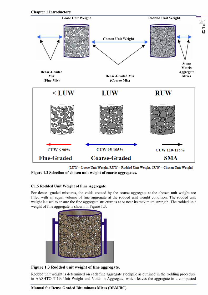
The designer needs to select the interlock of coarse aggregate desired in their mix design. Therefore, they choose a unit weight of coarse aggregate, which establishes the volume of coarse aggregate in the aggregate blend and the degree of aggregate interlock.
To select a chosen unit weight the designer needs to decide if the mixture is to be coarse-graded or fine-graded. Considerations for selecting a chosen unit weight are shown in Figure 1.2.
The loose unit weight is the lower limit of coarse aggregate interlock. Theoretically, it is the dividing line between fine-graded and coarse-graded mixtures. If the mix designer chooses a unit weight of coarse aggregate less than the loose unit weight, the coarse aggregate particles are spread apart and are not in a uniform particle-to-particle contact condition. Therefore, a fine aggregate skeleton is developed and properties for these blends are primarily related to the fine aggregate characteristics.
The rodded unit weight is generally considered to be the upper limit of coarse aggregate interlock for dense -graded mixtures. This value is typically near 110% of the loose unit weight. As the chosen unit weight approaches the rodded unit weight, the amount of compactive effort required for densification increases significantly, which can make a mixture difficult to construct in the field.
For dense-graded mixtures, the chosen unit weight is selected as a percentage of the loose unit weight of coarse aggregate. If the desire is to obtain some degree of coarse aggregate interlock (as with coarse-graded mixtures), the percentage used should range from 95% to 105% of the loose unit weight.
For all dense-graded mixtures, it is recommended the designer should not use a chosen unit weight in the range of 90% to 95% of the loose unit weight. Mixtures designed in this range have a high probability of varying in and out of coarse aggregate interlock in the field with the tolerances generally allowed on the PCS.
Chapter 1 Introductory
Manual for Dense Graded Bituminous Mixes (DBM/BC)
C1:
Loose Unit Weight Rodded Unit Weight
Chosen Unit Weight
Dense-Graded Mix Dense-Graded Mix
Stone Matrix
Aggregate Mixes
(Fine Mix) (Coarse Mix)
Figure 1.2 Selection of chosen unit weight of coarse aggregates.
C1.5 Rodded Unit Weight of Fine Aggregate
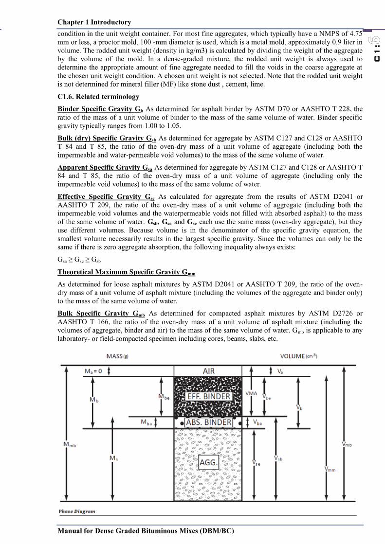
For dense- graded mixtures, the voids created by the coarse aggregate at the chosen unit weight are filled with an equal volume of fine aggregate at the rodded unit weight condition. The rodded unit weight is used to ensure the fine aggregate structure is at or near its maximum strength. The rodded unit weight of fine aggregate is shown in Figure 1.3.
Figure 1.3 Rodded unit weight of fine aggregate. Rodded unit weight is determined on each fine aggregate stockpile as outlined in the rodding procedure in AASHTO T-19: Unit Weight and Voids in Aggregate, which leaves the aggregate in a compacted
Chapter 1 Introductory
Manual for Dense Graded Bituminous Mixes (DBM/BC)
C1:
Loose Unit Weight Rodded Unit Weight
Chosen Unit Weight
Dense-Graded Mix Dense-Graded Mix
Stone Matrix
Aggregate Mixes
(Fine Mix) (Coarse Mix)
Figure 1.2 Selection of chosen unit weight of coarse aggregates.
C1.5 Rodded Unit Weight of Fine Aggregate
For dense- graded mixtures, the voids created by the coarse aggregate at the chosen unit weight are filled with an equal volume of fine aggregate at the rodded unit weight condition. The rodded unit weight is used to ensure the fine aggregate structure is at or near its maximum strength. The rodded unit weight of fine aggregate is shown in Figure 1.3.
Figure 1.3 Rodded unit weight of fine aggregate. Rodded unit weight is determined on each fine aggregate stockpile as outlined in the rodding procedure in AASHTO T-19: Unit Weight and Voids in Aggregate, which leaves the aggregate in a compacted
Chapter 1 Introductory
Manual for Dense Graded Bituminous Mixes (DBM/BC)
C1:
condition in the unit weight container. For most fine aggregates, which typically have a NMPS of 4.75 mm or less, a proctor mold, 100 -mm diameter is used, which is a metal mold, approximately 0.9 liter in volume. The rodded unit weight (density in kg/m3) is calculated by dividing the weight of the aggregate by the volume of the mold. In a dense-graded mixture, the rodded unit weight is always used to determine the appropriate amount of fine aggregate needed to fill the voids in the coarse aggregate at the chosen unit weight condition. A chosen unit weight is not selected. Note that the rodded unit weight is not determined for mineral filler (MF) like stone dust , cement, lime.
C1.6. Related terminology
Binder Specific Gravity Gb As determined for asphalt binder by ASTM D70 or AASHTO T 228, the ratio of the mass of a unit volume of binder to the mass of the same volume of water. Binder specific gravity typically ranges from 1.00 to 1.05.
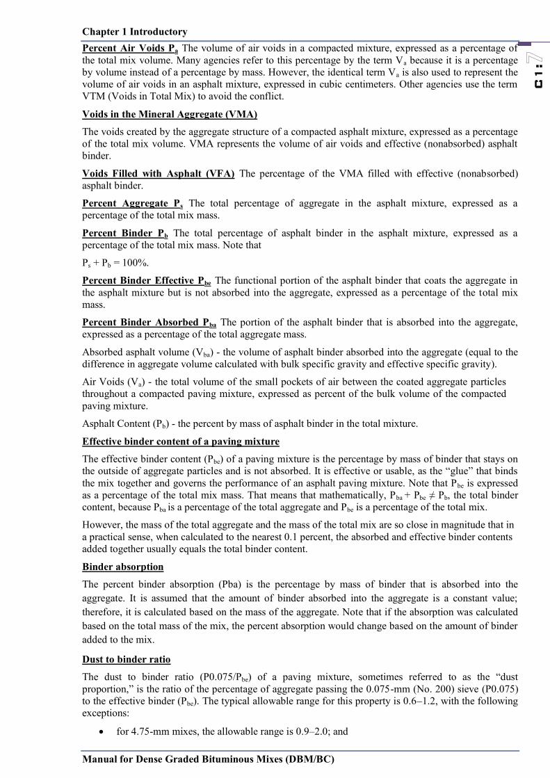
Bulk (dry) Specific Gravity Gsb As determined for aggregate by ASTM C127 and C128 or AASHTO T 84 and T 85, the ratio of the oven-dry mass of a unit volume of aggregate (including both the impermeable and water-permeable void volumes) to the mass of the same volume of water.
Apparent Specific Gravity Gsa As determined for aggregate by ASTM C127 and C128 or AASHTO T 84 and T 85, the ratio of the oven-dry mass of a unit volume of aggregate (including only the impermeable void volumes) to the mass of the same volume of water.
Effective Specific Gravity Gse As calculated for aggregate from the results of ASTM D2041 or AASHTO T 209, the ratio of the oven-dry mass of a unit volume of aggregate (including both the impermeable void volumes and the waterpermeable voids not filled with absorbed asphalt) to the mass of the same volume of water. Gsb, Gsa and Gse each use the same mass (oven-dry aggregate), but they use different volumes. Because volume is in the denominator of the specific gravity equation, the smallest volume necessarily results in the largest specific gravity. Since the volumes can only be the same if there is zero aggregate absorption, the following inequality always exists:
Gsa ≥ Gse ≥ Gsb
Theoretical Maximum Specific Gravity Gmm
As determined for loose asphalt mixtures by ASTM D2041 or AASHTO T 209, the ratio of the oven-dry mass of a unit volume of asphalt mixture (including the volumes of the aggregate and binder only) to the mass of the same volume of water.
Bulk Specific Gravity Gmb As determined for compacted asphalt mixtures by ASTM D2726 or AASHTO T 166, the ratio of the oven-dry mass of a unit volume of asphalt mixture (including the volumes of aggregate, binder and air) to the mass of the same volume of water. Gmb is applicable to any laboratory- or field-compacted specimen including cores, beams, slabs, etc.
Chapter 1 Introductory
Manual for Dense Graded Bituminous Mixes (DBM/BC)
C1:
Percent Air Voids Pa The volume of air voids in a compacted mixture, expressed as a percentage of the total mix volume. Many agencies refer to this percentage by the term Va because it is a percentage by volume instead of a percentage by mass. However, the identical term Va is also used to represent the volume of air voids in an asphalt mixture, expressed in cubic centimeters. Other agencies use the term VTM (Voids in Total Mix) to avoid the conflict.
Voids in the Mineral Aggregate (VMA)
The voids created by the aggregate structure of a compacted asphalt mixture, expressed as a percentage of the total mix volume. VMA represents the volume of air voids and effective (nonabsorbed) asphalt binder.
Voids Filled with Asphalt (VFA) The percentage of the VMA filled with effective (nonabsorbed) asphalt binder.
Percent Aggregate Ps The total percentage of aggregate in the asphalt mixture, expressed as a percentage of the total mix mass.
Percent Binder Pb The total percentage of asphalt binder in the asphalt mixture, expressed as a percentage of the total mix mass. Note that
Ps + Pb = 100%.
Percent Binder Effective Pbe The functional portion of the asphalt binder that coats the aggregate in the asphalt mixture but is not absorbed into the aggregate, expressed as a percentage of the total mix mass.
Percent Binder Absorbed Pba The portion of the asphalt binder that is absorbed into the aggregate, expressed as a percentage of the total aggregate mass.
Absorbed asphalt volume (Vba) - the volume of asphalt binder absorbed into the aggregate (equal to the difference in aggregate volume calculated with bulk specific gravity and effective specific gravity).
Air Voids (Va) - the total volume of the small pockets of air between the coated aggregate particles throughout a compacted paving mixture, expressed as percent of the bulk volume of the compacted paving mixture.
Asphalt Content (Pb) - the percent by mass of asphalt binder in the total mixture.
Effective binder content of a paving mixture
The effective binder content (Pbe) of a paving mixture is the percentage by mass of binder that stays on the outside of aggregate particles and is not absorbed. It is effective or usable, as the ―glue‖ that binds the mix together and governs the performance of an asphalt paving mixture. Note that Pbe is expressed as a percentage of the total mix mass. That means that mathematically, Pba + Pbe ≠ Pb, the total binder content, because Pba is a percentage of the total aggregate and Pbe is a percentage of the total mix.
However, the mass of the total aggregate and the mass of the total mix are so close in magnitude that in a practical sense, when calculated to the nearest 0.1 percent, the absorbed and effective binder contents added together usually equals the total binder content.
Binder absorption
The percent binder absorption (Pba) is the percentage by mass of binder that is absorbed into the aggregate. It is assumed that the amount of binder absorbed into the aggregate is a constant value; therefore, it is calculated based on the mass of the aggregate. Note that if the absorption was calculated based on the total mass of the mix, the percent absorption would change based on the amount of binder added to the mix.
Dust to binder ratio
The dust to binder ratio (P0.075/Pbe) of a paving mixture, sometimes referred to as the ―dust proportion,‖ is the ratio of the percentage of aggregate passing the 0.075-mm (No. 200) sieve (P0.075) to the effective binder (Pbe). The typical allowable range for this property is 0.6–1.2, with the following exceptions:
for 4.75-mm mixes, the allowable range is 0.9–2.0; and
Chapter 1 Introductory
Manual for Dense Graded Bituminous Mixes (DBM/BC)
C1:
for coarse-graded mixes whose gradation plots below the Primary Control Sieve (PCS) on a 0.45 power chart, the allowable range may be increased to 0.8–1.6.
In general, this property addresses the workability of asphalt mixtures. A low P0.075/Pbe often results in a tender mix, which lacks cohesion and is difficult to compact in the field because it tends to move laterally under the roller. Mixes tend to stiffen as the P0.075 increases, but too much will also result in a tender mix. A mix with a high P0.075/Pbe will often exhibit a multitude of small stress cracks during the compaction process, called check cracking. This property is usually calculated for dense-graded mixes only.
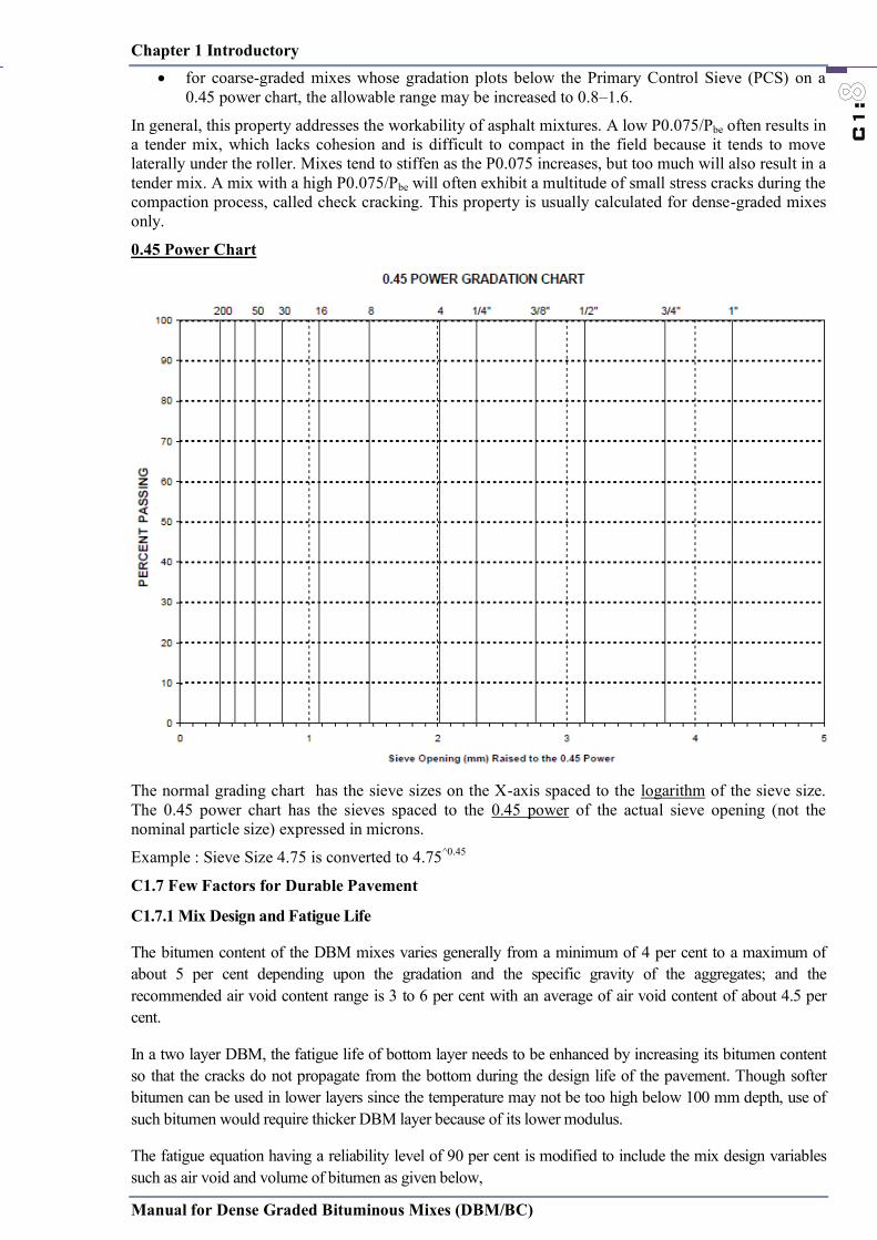
0.45 Power Chart
The normal grading chart has the sieve sizes on the X-axis spaced to the logarithm of the sieve size. The 0.45 power chart has the sieves spaced to the 0.45 power of the actual sieve opening (not the nominal particle size) expressed in microns.
Example : Sieve Size 4.75 is converted to 4.75^0.45
C1.7 Few Factors for Durable Pavement
C1.7.1 Mix Design and Fatigue Life
The bitumen content of the DBM mixes varies generally from a minimum of 4 per cent to a maximum of about 5 per cent depending upon the gradation and the specific gravity of the aggregates; and the recommended air void content range is 3 to 6 per cent with an average of air void content of about 4.5 per cent.
In a two layer DBM, the fatigue life of bottom layer needs to be enhanced by increasing its bitumen content so that the cracks do not propagate from the bottom during the design life of the pavement. Though softer bitumen can be used in lower layers since the temperature may not be too high below 100 mm depth, use of such bitumen would require thicker DBM layer because of its lower modulus.
The fatigue equation having a reliability level of 90 per cent is modified to include the mix design variables such as air void and volume of bitumen as given below,

Chapter 1 Introductory
Manual for Dense Graded Bituminous Mixes (DBM/BC)
C1:
Nf = 0.5161 * C * 10-04 x [1 /t ] 3.89 * [1 /MR]0.854
Where, C = 10M, M = 4.84 [ (Vb/(Va+Vb) - 0.69 ]
Va = per cent volume of air void and Vb = per cent volume of bitumen in a given volume of bituminous mix.
Nf = fatigue life, t = maximum tensile strain at the bottom of DBM, MR = Resilient modulus of bituminous mix.
Figure 1.4 Effect of Air Void and Volume of Bitumen on Fatigue Life Bituminous Layer (IRC 37-2012,Fig.1-2)
C1.7.2 Flexural Fatigue of Thin Wearing Course
When a thin wearing course of bituminous layer is provided over a granular layer, there is compressive bending strain due to a wheel load at the bottom of the bituminous layer which decreases with increasing thickness and becomes tensile with higher thickness as can be seen from Fig. l.5. Only when thickness reaches to about 50 mm, there is reduction in tensile strain with further increase in thickness of the bituminous layer.
Figure 1.5 Pavement thickness and strain relation
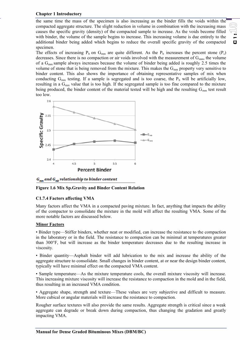
C1.7.3 Effect of binder content on Gmb and Gmm
The effects of asphalt binder content (Pb) on Gmb and Gmm are illustrated in Figure 1.6. It is important to remember that Gmb is measured on a compacted mixture sample. As Pb increases, more lubricity is added to the mixture which allows the specimen to compact and slightly reduce the volume, while at
( + )
( - )
Tens
ile S
trai
n
Thickness of Bituminous Layers
Chapter 1 Introductory
Manual for Dense Graded Bituminous Mixes (DBM/BC)
C1:
Nf = 0.5161 * C * 10-04 x [1 /t ] 3.89 * [1 /MR]0.854
Where, C = 10M, M = 4.84 [ (Vb/(Va+Vb) - 0.69 ]
Va = per cent volume of air void and Vb = per cent volume of bitumen in a given volume of bituminous mix.
Nf = fatigue life, t = maximum tensile strain at the bottom of DBM, MR = Resilient modulus of bituminous mix.
Figure 1.4 Effect of Air Void and Volume of Bitumen on Fatigue Life Bituminous Layer (IRC 37-2012,Fig.1-2)
C1.7.2 Flexural Fatigue of Thin Wearing Course
When a thin wearing course of bituminous layer is provided over a granular layer, there is compressive bending strain due to a wheel load at the bottom of the bituminous layer which decreases with increasing thickness and becomes tensile with higher thickness as can be seen from Fig. l.5. Only when thickness reaches to about 50 mm, there is reduction in tensile strain with further increase in thickness of the bituminous layer.
Figure 1.5 Pavement thickness and strain relation
C1.7.3 Effect of binder content on Gmb and Gmm
The effects of asphalt binder content (Pb) on Gmb and Gmm are illustrated in Figure 1.6. It is important to remember that Gmb is measured on a compacted mixture sample. As Pb increases, more lubricity is added to the mixture which allows the specimen to compact and slightly reduce the volume, while at
( + )
( - )
Tens
ile S
trai
n
Thickness of Bituminous Layers
Chapter 1 Introductory
Manual for Dense Graded Bituminous Mixes (DBM/BC)
C1:
the same time the mass of the specimen is also increasing as the binder fills the voids within the compacted aggregate structure. The slight reduction in volume in combination with the increasing mass causes the specific gravity (density) of the compacted sample to increase. As the voids become filled with binder, the volume of the sample begins to increase. This increasing volume is due entirely to the additional binder being added which begins to reduce the overall specific gravity of the compacted specimen. The effects of increasing Pb on Gmm are quite different. As the Pb increases the percent stone (Ps) decreases. Since there is no compaction or air voids involved with the measurement of Gmm, the volume of a Gmm sample always increases because the volume of binder being added is roughly 2.5 times the volume of stone that is being removed from the mixture. This makes the Gmm property very sensitive to binder content. This also shows the importance of obtaining representative samples of mix when conducting Gmm testing. If a sample is segregated and is too coarse, the Pb will be artificially low, resulting in a Gmm value that is too high. If the segregated sample is too fine compared to the mixture being produced, the binder content of the material tested will be high and the resulting Gmm test result too low.
Figure 1.6 Mix Sp.Gravity and Binder Content Relation C1.7.4 Factors affecting VMA
Many factors affect the VMA in a compacted paving mixture. In fact, anything that impacts the ability of the compactor to consolidate the mixture in the mold will affect the resulting VMA. Some of the more notable factors are discussed below.
Minor Factors
• Binder type—Stiffer binders, whether neat or modified, can increase the resistance to the compaction in the laboratory or in the field. The resistance to compaction can be minimal at temperatures greater than 300°F, but will increase as the binder temperature decreases due to the resulting increase in viscosity.
• Binder quantity—Asphalt binder will add lubrication to the mix and increase the ability of the aggregate structure to consolidate. Small changes in binder content, at or near the design binder content, typically will have minimal effect on the compacted VMA content.
• Sample temperature—As the mixture temperature cools, the overall mixture viscosity will increase. This increasing mixture viscosity will increase the resistance to compaction in the mold and in the field, thus resulting in an increased VMA condition.
• Aggregate shape, strength and texture—These values are very subjective and difficult to measure. More cubical or angular materials will increase the resistance to compaction.
Rougher surface textures will also provide the same results. Aggregate strength is critical since a weak aggregate can degrade or break down during compaction, thus changing the gradation and greatly impacting VMA.
Chapter 1 Introductory
Manual for Dense Graded Bituminous Mixes (DBM/BC)
C1:
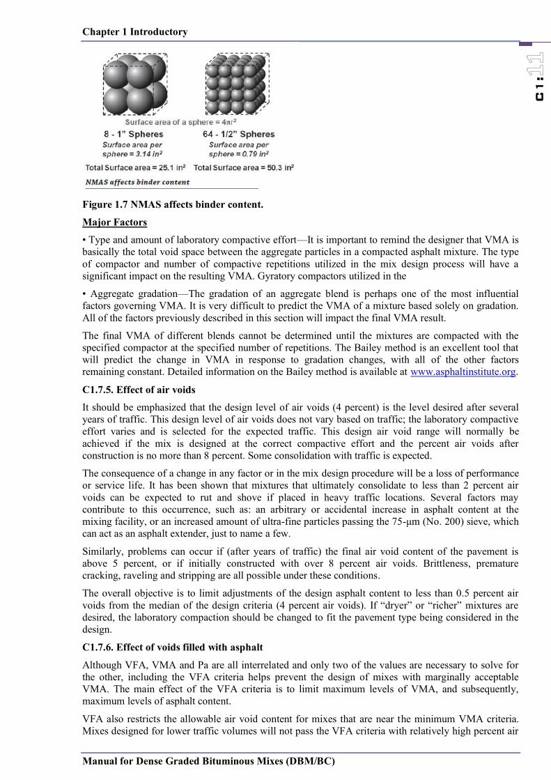
Figure 1.7 NMAS affects binder content.
Major Factors
• Type and amount of laboratory compactive effort—It is important to remind the designer that VMA is basically the total void space between the aggregate particles in a compacted asphalt mixture. The type of compactor and number of compactive repetitions utilized in the mix design process will have a significant impact on the resulting VMA. Gyratory compactors utilized in the
• Aggregate gradation—The gradation of an aggregate blend is perhaps one of the most influential factors governing VMA. It is very difficult to predict the VMA of a mixture based solely on gradation. All of the factors previously described in this section will impact the final VMA result.
The final VMA of different blends cannot be determined until the mixtures are compacted with the specified compactor at the specified number of repetitions. The Bailey method is an excellent tool that will predict the change in VMA in response to gradation changes, with all of the other factors remaining constant. Detailed information on the Bailey method is available at www.asphaltinstitute.org.
C1.7.5. Effect of air voids
It should be emphasized that the design level of air voids (4 percent) is the level desired after several years of traffic. This design level of air voids does not vary based on traffic; the laboratory compactive effort varies and is selected for the expected traffic. This design air void range will normally be achieved if the mix is designed at the correct compactive effort and the percent air voids after construction is no more than 8 percent. Some consolidation with traffic is expected.
The consequence of a change in any factor or in the mix design procedure will be a loss of performance or service life. It has been shown that mixtures that ultimately consolidate to less than 2 percent air voids can be expected to rut and shove if placed in heavy traffic locations. Several factors may contribute to this occurrence, such as: an arbitrary or accidental increase in asphalt content at the mixing facility, or an increased amount of ultra-fine particles passing the 75-μm (No. 200) sieve, which can act as an asphalt extender, just to name a few.
Similarly, problems can occur if (after years of traffic) the final air void content of the pavement is above 5 percent, or if initially constructed with over 8 percent air voids. Brittleness, premature cracking, raveling and stripping are all possible under these conditions.
The overall objective is to limit adjustments of the design asphalt content to less than 0.5 percent air voids from the median of the design criteria (4 percent air voids). If ―dryer‖ or ―richer‖ mixtures are desired, the laboratory compaction should be changed to fit the pavement type being considered in the design.
C1.7.6. Effect of voids filled with asphalt
Although VFA, VMA and Pa are all interrelated and only two of the values are necessary to solve for the other, including the VFA criteria helps prevent the design of mixes with marginally acceptable VMA. The main effect of the VFA criteria is to limit maximum levels of VMA, and subsequently, maximum levels of asphalt content.
VFA also restricts the allowable air void content for mixes that are near the minimum VMA criteria. Mixes designed for lower traffic volumes will not pass the VFA criteria with relatively high percent air

Chapter 1 Introductory
Manual for Dense Graded Bituminous Mixes (DBM/BC)
C1:
Figure 1.7 NMAS affects binder content.
Major Factors
• Type and amount of laboratory compactive effort—It is important to remind the designer that VMA is basically the total void space between the aggregate particles in a compacted asphalt mixture. The type of compactor and number of compactive repetitions utilized in the mix design process will have a significant impact on the resulting VMA. Gyratory compactors utilized in the
• Aggregate gradation—The gradation of an aggregate blend is perhaps one of the most influential factors governing VMA. It is very difficult to predict the VMA of a mixture based solely on gradation. All of the factors previously described in this section will impact the final VMA result.
The final VMA of different blends cannot be determined until the mixtures are compacted with the specified compactor at the specified number of repetitions. The Bailey method is an excellent tool that will predict the change in VMA in response to gradation changes, with all of the other factors remaining constant. Detailed information on the Bailey method is available at www.asphaltinstitute.org.
C1.7.5. Effect of air voids
It should be emphasized that the design level of air voids (4 percent) is the level desired after several years of traffic. This design level of air voids does not vary based on traffic; the laboratory compactive effort varies and is selected for the expected traffic. This design air void range will normally be achieved if the mix is designed at the correct compactive effort and the percent air voids after construction is no more than 8 percent. Some consolidation with traffic is expected.
The consequence of a change in any factor or in the mix design procedure will be a loss of performance or service life. It has been shown that mixtures that ultimately consolidate to less than 2 percent air voids can be expected to rut and shove if placed in heavy traffic locations. Several factors may contribute to this occurrence, such as: an arbitrary or accidental increase in asphalt content at the mixing facility, or an increased amount of ultra-fine particles passing the 75-μm (No. 200) sieve, which can act as an asphalt extender, just to name a few.
Similarly, problems can occur if (after years of traffic) the final air void content of the pavement is above 5 percent, or if initially constructed with over 8 percent air voids. Brittleness, premature cracking, raveling and stripping are all possible under these conditions.
The overall objective is to limit adjustments of the design asphalt content to less than 0.5 percent air voids from the median of the design criteria (4 percent air voids). If ―dryer‖ or ―richer‖ mixtures are desired, the laboratory compaction should be changed to fit the pavement type being considered in the design.
C1.7.6. Effect of voids filled with asphalt
Although VFA, VMA and Pa are all interrelated and only two of the values are necessary to solve for the other, including the VFA criteria helps prevent the design of mixes with marginally acceptable VMA. The main effect of the VFA criteria is to limit maximum levels of VMA, and subsequently, maximum levels of asphalt content.
VFA also restricts the allowable air void content for mixes that are near the minimum VMA criteria. Mixes designed for lower traffic volumes will not pass the VFA criteria with relatively high percent air
Chapter 1 Introductory
Manual for Dense Graded Bituminous Mixes (DBM/BC)
C1:
voids (5 percent) even though the air void criteria range are met. The purpose is to avoid less durable mixes in light traffic situations.
Mixes designed for heavy traffic will not pass the VFA criteria with relatively low percent air voids (less than 3.5 percent) even though that amount of air voids is within the acceptable range. Because low air void contents can be very critical in terms of permanent deformation (as discussed previously), the VFA criteria help to avoid those mixes that would be susceptible to rutting in heavy traffic situations.
The VFA criteria provide an additional factor of safety in the design and construction process in terms of performance. Since changes can occur between the design stage and actual construction, an increased margin for safety is desirable.

Chapter 1 Introductory
Manual for Dense Graded Bituminous Mixes (DBM/BC)
C1:
C1.8. Flow Chart for DBM/AC Application
Design Thickness
Checking the Design Thickness, meeting minimum thickness
requirement, Table 2.2
Selection of NMAS
Aggregate Source Selection
Bitumen Selection, as per “C.2.8.1 Choice of Bitumen Binder”
Verifying Aggregate as per
Table 2.3: Aggregate Consensus Properties Requirements
Table 2.4: Aggregate Source Properties for DBM/BC
Verifying Bitumen as per
Table : 2.10 : Bitumen property requirements
Mineral Filler selection as per Table
2.6: Requirement
Mix Design (Chapter 3)
For 25mm NMAS : Marshall Method for OBC Determination
For >25mm NMAS : Modified Marshall Method for OBC Determination
Outputs of Mix Design
Aggregate Proportion meeting Table 2.5 requirements; and C1.4 & C1.5 Binder / Dust Ration Optimum Binder Content, not less than value mention in Table 3.9 % of Air Void in Total Mix
Plant Calibration and Plant Trails (Chapter 4)
Field Trails (Chapter 5)
Field Operation and Verification (Chapter 5 & 6)
Chapter 2. Material Selection
Manual for Dense Graded Bituminous Mixes (DBM/BC)
C2:
C2.1 General
Regardless of the mixture classification, the same degree of design, production and construction control procedures should be used to ensure proper performance of the pavement. All quality pavements should be engineered to contain requirements for the following items:
properly selected asphalt binder grades for the climate and traffic; aggregate characteristics including material quality and gradation; HMA volumetric requirements; and HMA performance criteria, if warranted.
The amount of aggregates for asphalt concrete mixtures is generally 90 to 95 percent by weight and 75 to 85 percent by volume. Aggregates are primarily responsible for the load supporting capacity of a pavement. Aggregate has been defined as any inert mineral material used for mixing in graduated particles or fragments. It includes sand, gravel, crushed stone, slag, screenings, and mineral filler. Selecting an aggregate material for use in an asphalt concrete depends upon the availability, cost, and quality of the material, as well as the type of construction that is intended.
C2.2 Materials
(a) Bitumen
The bitumen should be viscosity grade paving bitumen complying with the Indian Standard Specification IS: 73, Table 2.10. Table 2.1 : Viscosity Grade and their general applications
Viscosity Grade )VG) General Applications VG -40 (40-60 Penetration ) Use of Highly Stressed Areas like intersection, toll both, truck
parking VG -30 (50-60 Penetration ) Use for paving mostly VG -20 (60-80 Penetration ) Use for paving in cold climate, high altitude region, hilly terrain VG -10 (80-100 Penetration ) Use in spraying applications and for paving in very cold regions
(b) Coarse Aggregates
The coarse aggregates should consist of crushed rock, crushed gravel or other hard material retained on the 4.75 mm sieve(for NMAS 35.5mm, 26.5mm & 19mm) or 2.36mm sieve(for NMAS 13.2mm). They should be clean, hard, and durable, of cubical shape, free from dust and soft or friable matter, organic or other deleterious substances. Where crushed gravel is proposed for use as aggregate, not less than 90 percent by weight of the crushed material retained on the 4.75 mm sieve should have at least two fractured faces.(Ref. Table 1.2.)
(c) Fine Aggregates
Fine aggregates should consist of crushed or naturally occurring mineral material, or a combination of the two, passing the 4.75 mm sieve(for NMAS 35.5mm, 26.5mm & 19mm) or 2.36mm sieve(for NMAS 13.2mm) and retained on the 75-micron sieve. These should be clean, hard, durable, dry and free from dust, and soft or friable matter, organic or other deleterious matter. Natural sand should not be allowed in binder courses. However, natural sand up to 50 percent of the fine aggregate may be allowed in base courses.(Ref. Table 1.2.)
(d) Filler
Filler should consist of finely divided mineral matter such as rock dust, hydrated lime or cement. The filler should be free from organic impurities and have a plasticity Index not greater than 4. The Plasticity index requirement should not apply if filler is cement or lime. Where the aggregates fail to

Chapter 2. Material Selection
Manual for Dense Graded Bituminous Mixes (DBM/BC)
C2:
meet the requirements of the water sensitivity test(80% as min. retained tensile strength, AASHTO T283) , then 2 percent by total weight of aggregate, of hydrated lime should be used and percentage of fine aggregate reduced accordingly.
C2.3 Lift thickness and aggregate size
Nominal aggregate size dictates lift thickness, so minimum lift thickness and aggregate size should always be considered together. Minimum lift thickness should be at least 3 times the nominal maximum aggregate size to ensure aggregate can align themselves during compaction to achieve required density and also to ensure mix is impermeable. Therefore, the desired lift thickness can direct the decision on nominal aggregate size to use.
The maximum lift thickness is dependent also upon the type of compaction equipment that is being used. When static steel-wheeled rollers are used, the maximum lift thickness that can be properly compacted is 75mm. When pneumatic or vibratory rollers are used, the maximum thickness of lift that can be compacted is almost unlimited. Generally, lift thicknesses are limited to 150 or 200 mm. Proper placement becomes a problem in lifts thicker than 150 or 200 mm.
MS-2 : Asphalt Mix Design Method, 7th Edition,Asphalt Institute has recommendations on the minimum thickness for a single lift of dense-graded asphalt mixtures are four times the nominal maximum aggregate size (NMAS) for all mixtures with the exception of “fine” graded mixtures that may be placed at three times the NMAS. Historical pavement thickness guidelines of two times the “top size” are inappropriate for NMAS-defined gradations and are susceptible to poor pavement performance.
Thickness of uncompacted asphalt = designed lift thickness x target density /mix loose density
Table 2.2: The limits on permissible lift thickness with reference of IRC :111:2009, Specification for Dense Graded Bituminous Mixes and the New York State Highway Design Manual
Specification Purpose No. of Layers Minimum lift thickness
Maximum lift thickness
DBM Base/Binder Course. Overlay for Strengthening
Single or Multiple
For NMAS 35.5mm : 100mm For NMAS 26.5mm: 75mm
For NMAS 35.5mm : 150mm For NMAS 26.5mm: 150mm
Bituminous Concrete(BC)/
Wearing Course Single For NMAS 19mm : 60mm For NMAS 13.2 mm: 40mm
For NMAS 19mm : 75mm For NMAS 13.2 mm: 50mm
C2.4 Consensus Aggregate Properties
Asphalt Institute_MS2_7th Edition_Asphalt Institute Mix Design Statement : ―Certain aggregate characteristics are critical to well-performing HMA and have been widely acknowledged by a wide range of industry experts.‖
These characteristics are called the “consensus” properties and are as follows: coarse aggregate angularity (CAA), fine aggregate angularity (FAA), flat and elongated particles (F&E), and clay content (SE value).
C.2.4.1 Coarse aggregate angularity
Coarse aggregate angularity (CAA) ensures a high degree of aggregate internal friction for rutting resistance by specifying a minimum percentage of angular particles in the asphalt mixture. The test method is ASTM D 5821, ―Determining the Percentage of Fractured Particles in Coarse Aggregate.‖
Chapter 2. Material Selection
Manual for Dense Graded Bituminous Mixes (DBM/BC)
C2:
The test method determines the percentage of aggregate pieces larger than the #4 sieve (4.75 mm) meeting specified angularity criteria, either by mass or particle count. The reporting format gives both the percentage of aggregate with one or more fractured faces and with two or more fractured faces. For example, a reported value of ―85/80‖ indicates that 85 percent of the sample has one or more fractured faces and 80 percent has two or more fractured faces. Table 2.3 gives the required minimum values for coarse aggregate angularity as a function of traffic level and position within the pavement.
C.2.4.2 Fine aggregate angularity
Fine aggregate angularity (FAA) ensures a high degree of fine aggregate internal friction and rutting resistance. It is defined as the percent of air voids present in loosely compacted aggregates smaller than the #8 sieve (2.36 mm). The test method specified is AASHTO T 304, ―Uncompacted Void Content of Fine Aggregate.‖ This property is influenced by particle shape, surface texture and grading. Higher void contents typically mean more fractured faces. In the test procedure, a sample of fine, washed and dried aggregate is poured into a small calibrated cylinder through a standard funnel (Figure 2.1).
Figure 2.1 : Fine Aggregate Angularity Apparatus
By measuring the mass of fine aggregate (F) in the filled cylinder of known volume (V), the void content can be calculated as the difference between the cylinder volume and fine aggregate volume collected in the cylinder. The fine aggregate bulk (dry) specific gravity (Gsb) is used to compute the fine aggregate volume. Table 2.3 gives the required minimum values for fine aggregate angularity (Uncompacted Void Content of Fine Aggregate) as a function of traffic level and position within the pavement.
C.2.4.3 Flat and elongated particles
Figure 2.2 Measuring Flat and Elongated Particles

Chapter 2. Material Selection
Manual for Dense Graded Bituminous Mixes (DBM/BC)
C2:
Flat and elongated particles (F&E) is the percentage by mass or by particle count of coarse aggregates that have a maximum-to-minimum dimension ratio greater than 5:1 (or other ratio, depending on the agency specification). Flat and elongated particles are undesirable because they have a tendency to break during construction and under traffic and they tend to reduce VMA. The test procedure used is ASTM D4791, which deals with flat and elongated particles, and is performed on coarse aggregate larger than the #4 sieve (4.75 mm). The procedure uses a proportional caliper device (Figure 2.2) to measure the dimensional ratio of a representative sample of aggregate particles. In Figure 2.2, the aggregate particle is first placed with its largest dimension between the swinging arm and fixed post at position (A). The swinging arm then remains stationary while the aggregate is placed between the swinging arm and the fixed post at position (B). If the aggregate passes through this gap, then it is counted as a flat and elongated particle. Maximum values for flat and elongated particles specified in AASHTO M 323 are given in Table 2.3.
The criteria for these consensus aggregate properties are based on traffic level and position within the pavement structure. Materials near the pavement surface subjected to high traffic levels require more stringent consensus properties. The criteria are intended to be applied to a proposed aggregate blend rather than individual components.
Table 2.3: Aggregate Consensus Properties Requirements
Design ESALs1
(In Millions)
Coarse Aggregate Angularity
(CAA) (Percent), minimum
Un-compacted Void Content of Fine
Aggregate Angularity (FAA) (Percent),
minimum
Sand Equivalent
(SE) (Percent), minimum
Flat and Elongated3'
(F&E) (Percent), maximum ≤100 mm > 100 mm ≤100 mm > 100 mm
< 0.3 55/- -/- - - 40 -
0.3 to < 3 75/- 50/- 40 40 40 10
3 to < 10 85/802 60/- 45 40 45 10
10 to < 30 95/90 80/75 45 40 45 10
≥30 100/100 100/100 45 45 50 10
NOTES:
1. Design ESALs are the anticipated traffic level expected on the design lane over a 20-year period. Regardless of the actual design life of the roadway, determine the design ESALs for 20 years to choose the appropriate aggregate criteria.
2. 85/80 denotes that 85 percent of the coarse aggregate has one or more fractured faces and 80 percent has two or more fractured faces.
3. Criterion based upon a 5:1 maximum-to-minimum ratio.
C.2.4.4 Clay content (sand equivalent)
Clay content, more commonly described as sand equivalent (SE), is a percentage of clay material measured on the aggregate fraction that is finer than a #4 sieve (4.75 mm). It is measured by AASHTO T 176, ―Plastic Fines in Graded Aggregates and Soils by Use of the Sand Equivalent Test (ASTM D2419).‖ or IS 2720 Part 37. A sample of fine aggregate is mixed with a flocculating solution in a graduated cylinder and agitated to loosen clayey fines present in and coating the aggregate (Figure 2.3). The flocculating solution forces the clay material into suspension above the granular aggregate. After a settling period, the cylinder height of suspended clay and settled sand is measured. The sand equivalent
Chapter 2. Material Selection
Manual for Dense Graded Bituminous Mixes (DBM/BC)
C2:
value is computed as the ratio of the sand to clay height readings, expressed as percentage. In essence, this determines how sandy the fine aggregate fraction is.
Figure 2.3 Sand Equivalent Test
C2.5 Source aggregate properties
In addition to the consensus aggregate properties, certain other aggregate characteristics are critical. However, critical values of these properties could not be reached by consensus because needed values are source specific. Consequently, a set of source properties is recommended. Specified values are established by local agencies. While these properties are relevant during the mix design process, they may also be used for source acceptance control. Those properties are toughness, soundness and deleterious materials.
C2.5.1 Toughness
Toughness tests estimate the resistance of coarse aggregate to abrasion and mechanical degradation during handling, construction and in-service. The most common toughness test is the Los Angeles Abrasion test IS:2386 Part IV which measures the percent loss of material from the coarse aggregate fraction of a standardized test sample. It is performed by subjecting the coarse aggregate, usually larger than the #8 sieve (2.36 mm), to tumbling and the impact and grinding by steel spheres. The test result is the mass percentage of coarse material lost during the test due to the mechanical degradation. The maximum allowable loss value is Table 2.4. The higher the value, the more friable the coarse aggregate, and the greater the breakdown (degradation) of the aggregate from quarrying through stockpiling, HMA manufacturing and under the rollers. The lower the value, the better the skid resistance and tire chain wear resistance of the pavement.
C2.5.2 Soundness
Soundness tests estimate the resistance of aggregates to in-service weathering. The most common test is Soundness of Aggregate By Use of Sodium Sulfate or Magnesium Sulfate (IS:2386 Part V) which measures the percent loss of material from an aggregate blend. It can be performed on both coarse and fine aggregate. The test is performed by exposing an aggregate sample to repeated immersions in saturated solutions of sodium or magnesium sulfate followed by oven drying. One immersion and drying is considered one soundness cycle. During the drying phase, salts precipitate in the permeable void space of the aggregate. Upon re-immersion, the salt rehydrates and exerts internal expansive forces that simulate the expansive forces of freezing water. The test result is total percent loss over various

Chapter 2. Material Selection
Manual for Dense Graded Bituminous Mixes (DBM/BC)
C2:
sieve intervals for a required number of cycles. The maximum allowable loss value is Table 2.4 for five cycles. Magnesium sulfate testing is typically more aggressive than sodium sulfate testing. It is typical for magnesium sulfate loss to be greater than sodium sulfate loss on the same aggregate.
C2.5.3 Deleterious materials
Deleterious materials are defined as the mass percentage of contaminants such as clay lumps, shale, wood, mica and coal in the blended aggregate. The most common deleterious materials test is Clay Lumps and Friable Particles in Aggregate (IS:2386 Part I). The analysis can be performed on both coarse and fine aggregate. The test is performed by wet sieving aggregate size fractions over specified sieves. The mass percentage of material lost as a result of wet sieving is reported as the percent of clay lumps and friable particles. A wide range of criteria for maximum allowable percentage of deleterious particles exists. The maximum allowable value is Table 2.4.
Table 2.4: Aggregate Source Properties for DBM/BC
Property Test Specification Method of Test
Deleterious materials:
Cleanliness (dust)
Grain size analysis Max 5% passing 0.075 mm sieve
IS:2386 Part I
Toughness/Strength Los Angeles Abrasion Value or
Aggregate Impact Value
DBM : Max 35%
BC : Max. 30%
DBM: Max 27%
BC : Max. 24%
IS:2386 Part IV
Durability Soundness either: Sodium Sulphate or
Magnesium Sulphate
Max 12%
Max 18%
IS:2386 Part V
Polishing Polished Stone Value Min 55 BS:812-114
Water Sensitivity Retained Tensile Strength*
Min 80% AASHTO 283
Water Absorption Water Absorption Max 2% IS:2386.Part Ill
Stripping Coating and Stripping of Bitumen Aggregate Mix
Minimum retained coating 95%
IS: 6241
*If the minimum retained tensile test strength falls below 80 percent, use of anti-stripping agent is recommended to meet the requirement.
C2.6 Gradation
It has long been established that the gradation of the aggregate is one of the factors that must be carefully considered in the design of asphalt paving mixtures. The purpose for establishing and controlling aggregate gradation is to provide a sufficient volume of voids in the asphalt-aggregate mixture to accommodate the proper asphalt film thickness on each particle and provide the design air void system to allow for thermal expansion of the asphalt within the mix. Minimum voids in the mineral aggregate (VMA) requirements have been established that vary with the nominal maximum aggregate size to help assure the correct volume of effective binder exists for each mix type.
Chapter 2. Material Selection
Manual for Dense Graded Bituminous Mixes (DBM/BC)
C2:
The gradation of each aggregate material utilized in a mixture should be conducted using the washed sieve analysis procedures designated in IS:2386 Part I or ASTM C117 and C136 to properly account for the #200 material. The results should be reported as an accumulative percent passing each respective specified sieve size and reported to the nearest whole percent passing. The exception is the percent passing the #200 sieve (0.075 mm), which should always be calculated and reported to the nearest 0.1 percent passing.
Control points
The control points define the type of mix and act as master ranges between which gradations must pass. Control points are placed at the nominal maximum size, an intermediate size (2.36 mm), and the smallest size (0.075 mm). Control point limits vary depending on the nominal maximum aggregate size of the design mixture as shown in Table 2.5.
Table 2.5: Gradation requirement Composition for BC DBM
Nominal Maximum aggregate size(NMAS)
13.2 mm 19 mm 26.5 mm 35.5 mm
Gradation Type (Ref. Table1.1) IS Sieve (mm) Cumulative % by weight of total aggregate
passing 45 100
37.5 100 95-100 26.5 100 90-100 63-93 19 100 90-100 71-95 -
13.2 90-100 59-79 56-80 55-75 9.5 70-88 52-72 - - 4.75 53-71 35-55 38-54 38-54 2.36 42-58 28-44 28-42 28-42 1.18 34-48 20-34 - - 0.6 26-38 15-27 - - 0.3 18-28 10-20 7-21 7-21 0.15 12-20 5-13 - - 0.075 4-10 2-8 2-8 2-8
To avoid gap grading, the combined aggregate gradation should not vary from the lower limit on one sieve to higher limit on the adjacent sieve.
Typically, multiple stockpiles of aggregate are blended to meet the final specified requirements. A washed sieve analysis must be performed on every aggregate ingredient to be utilized in the mixture in order to calculate the final aggregate blend in the mixture to be designed. Most aggregate specifications are based on the final blend of the mixture.
Calculating a blended gradation, assuming all aggregate fractions have a similar Bulk Specific Gravity (Gsb):
P = (A × a) + (B × b) + (C × c) + . . .
where,
P = the blended percent passing for a given sieve
A, B, C, = the percent passing a sieve for an individual stockpile

Chapter 2. Material Selection
Manual for Dense Graded Bituminous Mixes (DBM/BC)
C2:
a,b,c, = proportion of stockpile to be added in the blend, where total = 1.00.
The above-mentioned gradation and blending operations result in an aggregate size distribution based on percentage of mass. Volumetric properties such as air voids and VMA are directly impacted by the amount and size of aggregate particles and the resulting packing characteristics in the final mixture. A gradation can give insight to the final volumetric properties in a particular mixture.
However, when the specific gravities of the individual aggregates differ or vary significantly (by 0.20 or more), the blended gradation, based on the mass of the aggregates, may have different volumetric characteristics when compared to an equivalent gradation of materials having similar specific gravities. Consider the following example where we are given two different mixtures to compare. They both have similar gradations by mass and equivalent aggregate shape, strength and texture. One mix contains aggregates of similar specific gravity and the other contains aggregates of widely differing specific gravity. Based on the gradation, it would be reasonable to assume that the resulting volumetric properties would be similar, but the actual number and sizes of particles in the mixture are not similar and the resulting volumetrics in the compacted mixture will be different. Table 2.6: Grading Requirements for Mineral Filler
IS sieve (mm) Cumulative Percent Passing by Weight of Total Aggregate
0.6 100 0.3 98-100
0.075 85.-100
Field-produced mixtures with significantly different aggregate specific gravities than those used in the mix design will also yield different hot mix volumetric properties. This is one of the reasons why most specifications require a new mix design when the source (and characteristics) of any of the mix ingredients are changed.
Cha
pter
2. M
ater
ial S
elec
tion
Man
ual f
or D
ense
Gra
ded
Bitu
min
ous M
ixes
(DB
M/B
C)
C2:
Figu
re 2
.4 :
Max
imum
Den
sity
line
and
Upp
er-L
ower
Lim
it of
Gra
datio
n as
per
spec
ifica
tion
in 0
.45
Pow
er C
hart
(13.
2mm
NM
AS
)
0102030405060708090100 0.
000.
501.
001.
502.
002.
503.
003.
504.
00
Percentage Passing
Seiv
ed R
aise
d to
the
0.45
Pow
er
Grad
iatio
n Ra
nge
for 1
3.2m
m N
MA
13.2
mm
NM
A (U
L)
13.2
mm
NM
A (L
L)
13.2
mm
NM
A G
radi
atio
n fo
r Max
. Den
sity

Cha
pter
2. M
ater
ial S
elec
tion
Man
ual f
or D
ense
Gra
ded
Bitu
min
ous M
ixes
(DB
M/B
C)
C2:
Figu
re 2
.5 :
Max
imum
Den
sity
line
and
Upp
er-L
ower
Lim
it of
Gra
datio
n as
per
spec
ifica
tion
in 0
.45
Pow
er C
hart
(19
mm
NM
AS
)
0102030405060708090100 0.
000.
501.
001.
502.
002.
503.
003.
504.
00
Percentage Passing
Seiv
ed R
aise
d to
the
0.45
Pow
er
Grad
iatio
n Ra
nge
for 1
9mm
NM
A
19m
m N
MA
(UL)
19m
m N
MA(
LL)
19m
mN
MA
Gra
diat
ion
for M
ax. D
ensit
y

Cha
pter
2. M
ater
ial S
elec
tion
Man
ual f
or D
ense
Gra
ded
Bitu
min
ous M
ixes
(DB
M/B
C)
C2:
Figu
re 2
.6 :
Max
imum
Den
sity
line
and
Upp
er-L
ower
Lim
it of
Gra
datio
n as
per
spec
ifica
tion
in 0
.45
Pow
er C
hart
(26.
5mm
NM
AS
)
0102030405060708090100 0.
001.
002.
003.
004.
005.
006.
00
Percentage Passing
Seiv
ed R
aise
d to
the
0.45
Pow
er
Grad
iatio
n Ra
nge
for 2
6.5m
m N
MA
26.5
mm
NM
A (U
L)
26.5
mm
NM
A (L
L)
26.5
mm
NM
A G
radi
atio
n fo
r Max
. Den
sity
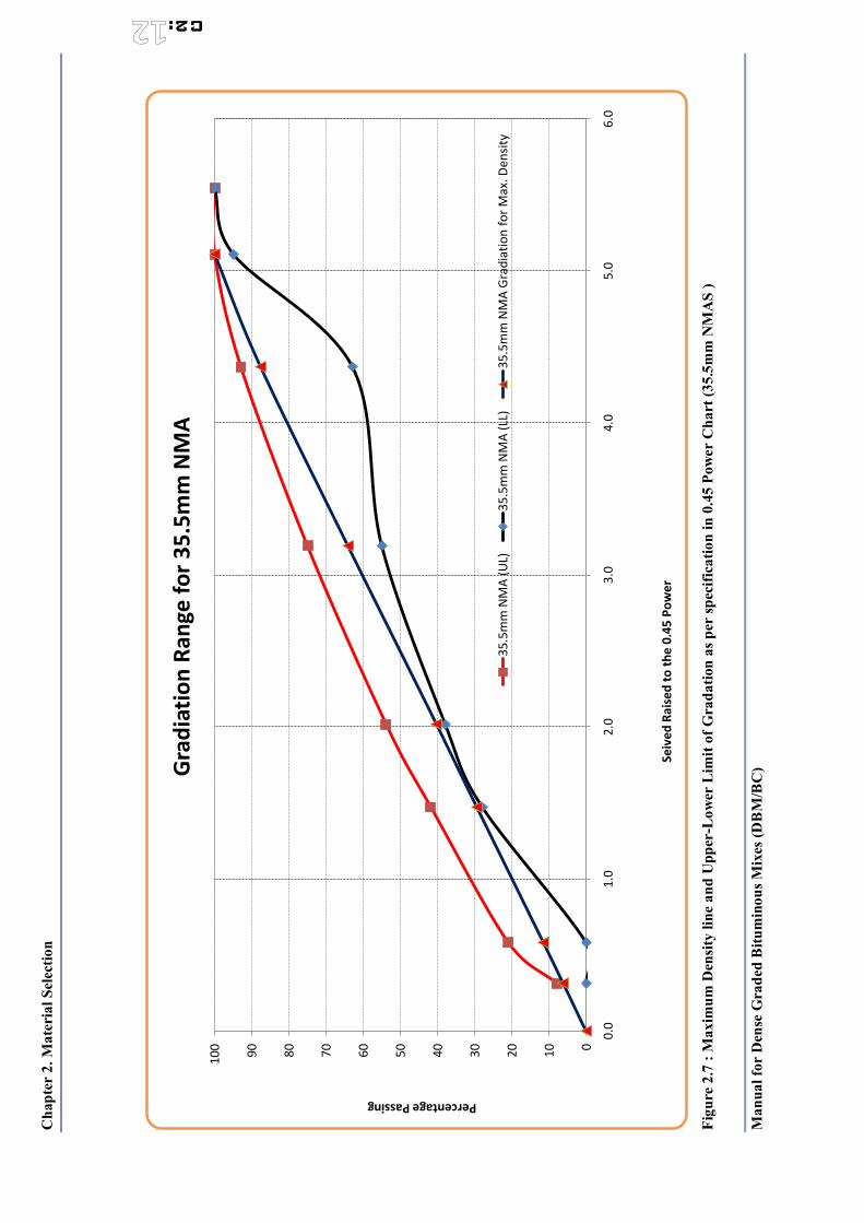
Cha
pter
2. M
ater
ial S
elec
tion
Man
ual f
or D
ense
Gra
ded
Bitu
min
ous M
ixes
(DB
M/B
C)
C2:
Figu
re 2
.7 :
Max
imum
Den
sity
line
and
Upp
er-L
ower
Lim
it of
Gra
datio
n as
per
spec
ifica
tion
in 0
.45
Pow
er C
hart
(35.
5mm
NM
AS
)
0102030405060708090100
0.0
1.0
2.0
3.0
4.0
5.0
6.0
Percentage Passing
Seiv
ed R
aise
d to
the
0.45
Pow
er
Grad
iatio
n Ra
nge
for 3
5.5m
m N
MA
35.5
mm
NM
A (U
L)35
.5m
m N
MA
(LL)
35.5
mm
NM
A G
radi
atio
n fo
r Max
. Den
sity
Chapter 2. Material Selection
Manual for Dense Graded Bituminous Mixes (DBM/BC)
C2:
C2.7 Specific gravity
The specific gravity of an aggregate is the ratio of the weight of a unit volume of material to the weight of the same volume of water at 73.4°F (23.0°C). This property is used in mix volumetric calculations for voids determination. Also, bulk specific gravities are used in the computations for adjusting quantities of the aggregate components that are to be used in an HMA mix because of the differing specific gravities of various aggregates.
The three generally accepted types of specific gravities for aggregate use in hot mix asphalt are the following:
• apparent specific gravity (Gsa);
• bulk (dry) specific gravity (Gsb); and
• effective specific gravity (Gse).
Apparent specific gravity considers the volume as being the volume of the aggregate itself. It does not include the volume of any pores or capillaries that become filled with water after a 15- to 19-hour soaking. Bulk (dry) specific gravity considers the overall volume of the aggregate particle, including the pores that become filled with water after a 15- to 19-hour soaking.
The effective specific gravity considers the overall volume of the aggregate excluding the volume of pores that absorb asphalt. Whereas bulk and apparent specific gravities can relate to individual aggregates or combined aggregates, effective specific gravity relates exclusively to the total combined aggregate structure in a mix of HMA.
The accuracy of specific gravity measurements for mix designs is important. Unless specific gravities are determined to four significant figures (three decimal places), an error in air voids value of as much as 0.8 percent can occur. The Asphalt Institute recommends the use of weigh scales whose sensitivity will allow a mix batch weighing 1,000 to 5,000 grams to be measured to an accuracy of 0.1 gram.
C2.7.1 Bulk (dry) specific gravity of aggregate
It is recommended that the bulk (dry) specific gravity (Gsb) of each aggregate be determined on samples submitted for mix design. Some stockpiles will be essentially coarse (retained on the No. 4 [4.75 mm] sieve), some will be fine (passing the No. 4 [4.75 mm] sieve) and some will have both coarse and fine portions.
Determining coarse aggregate Gsb
The coarse Gsb is determined using AASHTO T 85 or ASTM C127. The size of the test sample is specified and determined by the nominal maximum aggregate size. This procedure requires that the dry aggregate be saturated to determine the volume of the aggregate plus the water-permeable voids.
𝐺𝐺𝑠𝑠𝑏𝑏𝑚𝑚𝑣𝑣𝜌𝜌
𝑚𝑚𝑎𝑎𝑠𝑠𝑠𝑠 𝑜𝑜𝑓𝑓 𝑜𝑜𝑣𝑣𝑒𝑒𝑛𝑛 𝑑𝑑𝑟𝑟𝑦𝑦 𝑎𝑎𝑔𝑔𝑔𝑔𝑟𝑟𝑒𝑒𝑔𝑔𝑎𝑎𝑡𝑡𝑒𝑒 𝑣𝑣𝑜𝑜𝑙𝑙𝑢𝑢𝑚𝑚𝑒𝑒 𝑜𝑜𝑓𝑓 𝑎𝑎𝑔𝑔𝑔𝑔𝑟𝑟𝑒𝑒𝑔𝑔𝑎𝑎𝑡𝑡𝑒𝑒 𝑤𝑤𝑎𝑎𝑡𝑡𝑒𝑒𝑟𝑟 𝑝𝑝𝑒𝑒𝑟𝑟𝑚𝑚𝑒𝑒𝑎𝑎𝑏𝑏𝑙𝑙𝑒𝑒 𝑣𝑣𝑜𝑜𝑖𝑖𝑑𝑑𝑠𝑠 𝑥𝑥 𝜌𝜌
Notice that this equation mirrors the equation in the test procedure:
𝐺𝐺𝑠𝑠𝑏𝑏𝐴𝐴
𝐵𝐵 − 𝐶𝐶
where:
Gsb = bulk (dry) specific gravity of the aggregate
A = mass of the oven-dry test sample
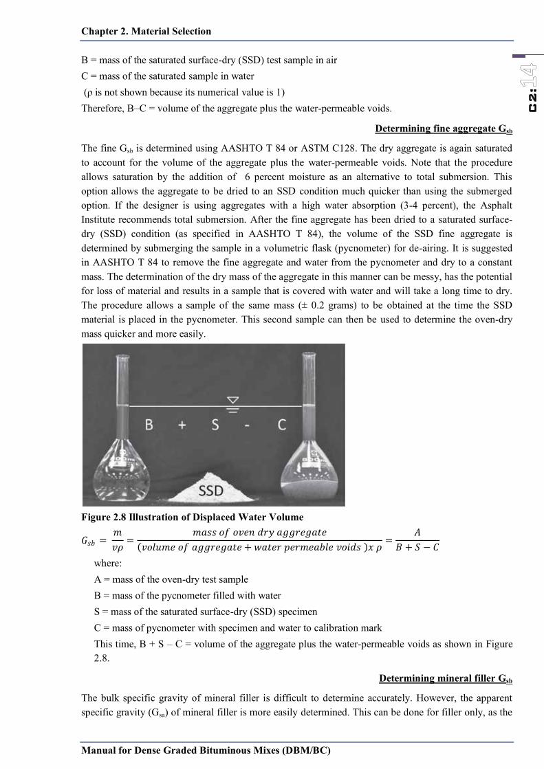
Chapter 2. Material Selection
Manual for Dense Graded Bituminous Mixes (DBM/BC)
C2:
B = mass of the saturated surface-dry (SSD) test sample in air C = mass of the saturated sample in water (ρ is not shown because its numerical value is 1) Therefore, B–C = volume of the aggregate plus the water-permeable voids.
Determining fine aggregate Gsb
The fine Gsb is determined using AASHTO T 84 or ASTM C128. The dry aggregate is again saturated to account for the volume of the aggregate plus the water-permeable voids. Note that the procedure allows saturation by the addition of 6 percent moisture as an alternative to total submersion. This option allows the aggregate to be dried to an SSD condition much quicker than using the submerged option. If the designer is using aggregates with a high water absorption (3-4 percent), the Asphalt Institute recommends total submersion. After the fine aggregate has been dried to a saturated surface-dry (SSD) condition (as specified in AASHTO T 84), the volume of the SSD fine aggregate is determined by submerging the sample in a volumetric flask (pycnometer) for de-airing. It is suggested in AASHTO T 84 to remove the fine aggregate and water from the pycnometer and dry to a constant mass. The determination of the dry mass of the aggregate in this manner can be messy, has the potential for loss of material and results in a sample that is covered with water and will take a long time to dry. The procedure allows a sample of the same mass (± 0.2 grams) to be obtained at the time the SSD material is placed in the pycnometer. This second sample can then be used to determine the oven-dry mass quicker and more easily.
Figure 2.8 Illustration of Displaced Water Volume
𝐺𝐺𝑠𝑠𝑏𝑏𝑚𝑚𝑣𝑣𝜌𝜌
𝑚𝑚𝑎𝑎𝑠𝑠𝑠𝑠 𝑜𝑜𝑓𝑓 𝑜𝑜𝑣𝑣𝑒𝑒𝑛𝑛 𝑑𝑑𝑟𝑟𝑦𝑦 𝑎𝑎𝑔𝑔𝑔𝑔𝑟𝑟𝑒𝑒𝑔𝑔𝑎𝑎𝑡𝑡𝑒𝑒 𝑣𝑣𝑜𝑜𝑙𝑙𝑢𝑢𝑚𝑚𝑒𝑒 𝑜𝑜𝑓𝑓 𝑎𝑎𝑔𝑔𝑔𝑔𝑟𝑟𝑒𝑒𝑔𝑔𝑎𝑎𝑡𝑡𝑒𝑒 𝑤𝑤𝑎𝑎𝑡𝑡𝑒𝑒𝑟𝑟 𝑝𝑝𝑒𝑒𝑟𝑟𝑚𝑚𝑒𝑒𝑎𝑎𝑏𝑏𝑙𝑙𝑒𝑒 𝑣𝑣𝑜𝑜𝑖𝑖𝑑𝑑𝑠𝑠 𝑥𝑥 𝜌𝜌
𝐴𝐴𝐵𝐵 𝑆𝑆 − 𝐶𝐶
where: A = mass of the oven-dry test sample B = mass of the pycnometer filled with water S = mass of the saturated surface-dry (SSD) specimen C = mass of pycnometer with specimen and water to calibration mark This time, B + S – C = volume of the aggregate plus the water-permeable voids as shown in Figure 2.8.
Determining mineral filler Gsb
The bulk specific gravity of mineral filler is difficult to determine accurately. However, the apparent specific gravity (Gsa) of mineral filler is more easily determined. This can be done for filler only, as the
Chapter 2. Material Selection
Manual for Dense Graded Bituminous Mixes (DBM/BC)
C2:
amount of mineral filler added is typically small and the difference between Gsb and Gsa is relatively small. DOR approval would be necessary for this substitution
Determining the composite Gsb for one stockpile For stockpiles that include both a coarse and fine fraction, one value must be determined for the stockpile. The average Gsb can be calculated as follows:
𝐺𝐺𝑠𝑠𝑏𝑏𝑃𝑃𝑐𝑐𝑜𝑜𝑎𝑎𝑟𝑟𝑠𝑠𝑒𝑒 𝑃𝑃𝑓𝑓𝑖𝑖𝑛𝑛𝑒𝑒𝑃𝑃𝑐𝑐𝑜𝑜𝑎𝑎𝑟𝑟𝑠𝑠𝑒𝑒𝐺𝐺𝑐𝑐𝑜𝑜𝑎𝑎𝑟𝑟𝑠𝑠𝑒𝑒
𝑃𝑃𝑓𝑓𝑖𝑖𝑛𝑛𝑒𝑒𝐺𝐺𝑓𝑓𝑖𝑖𝑛𝑛𝑒𝑒
where:
Gsb = bulk (dry) specific gravity of the aggregate
Pcoarse = percentage by weight retained on the No. 4 (4.75 mm) sieve
Pfine = percentage by weight passing the No. 4 (4.75 mm) sieve
Gcoarse = bulk (dry) specific gravity of the coarse fraction
Gfine = bulk (dry) specific gravity of the fine fraction
Determining the Gsb for the aggregate blend
Once the bulk (dry) specific gravity for each stockpile has been determined, the combined bulk (dry) specific gravity for the total aggregate blend is calculated as follows:
𝐺𝐺𝑠𝑠𝑏𝑏𝑃𝑃 𝑃𝑃 … 𝑃𝑃𝑛𝑛𝑃𝑃𝐺𝐺
𝑃𝑃𝐺𝐺 … 𝑃𝑃𝑛𝑛
𝐺𝐺𝑛𝑛
where:
Gsb = bulk (dry) specific gravity of the aggregate
P1, P2, Pn = percentages by weight of aggregates 1, 2, through n
G1, G2, Gn = bulk (dry) specific gravity of aggregates 1, 2, through n
This equation is useful for estimating Gsb during trials in the design process. The calculated coarse and fine Gsb can be verified by batching the combined aggregates, splitting them on the 4.75-mm sieve and determining the coarse and fine Gsb for the design. This process of splitting the aggregate blend on the 4.75- mm sieve and only running Gsb values on the coarse and fine fractions of the blend is often utilized for mix design verification and quality control testing on plant-produced mix in the field.
The equation format for calculating the combined bulk (dry) specific gravity uses the weighted harmonic mean. This method is necessary because the criteria being averaged involve a ratio. In this case, the percentages are all by weight, but the specific gravity is a ratio of the density of the material to the density of water. The equation for calculating the combined average absorption uses the weighted arithmetic mean, because each absorption is a percentage by weight, with no supplemental ratio involved.
Calculate the Gsa and absorption for the aggregate blend
Laboratory testing to determine the bulk specific gravity (Gsb) also provides data to easily determine two additional aggregate properties, the apparent specific gravity (Gsa) and the water absorption of the aggregate. These calculations are not required to determine mixture volumetric properties; however, they are valuable tools for the mix designer to monitor. The absorption of the aggregate indicates several characteristics of the final mixture. Highly absorptive aggregates will require additional binder to fill the permeable voids in the aggregate, which increases cost. It is not uncommon for aggregates to absorb a binder amount equal to 40–80 percent of the water-permeable voids.

Chapter 2. Material Selection
Manual for Dense Graded Bituminous Mixes (DBM/BC)
C2:
Gsa is the ratio of the mass of the oven-dry aggregate to the volume of the aggregate excluding the volume of the voids occupied by absorbed water. The Gsa volume is less than the volume used to calculate the Gsb; therefore, the Gsa value will always be larger than the Gsb value.
𝐺𝐺𝑠𝑠𝑎𝑎𝑚𝑚𝑣𝑣𝜌𝜌
𝑚𝑚𝑎𝑎𝑠𝑠𝑠𝑠 𝑜𝑜𝑓𝑓 𝑜𝑜𝑣𝑣𝑒𝑒𝑛𝑛 𝑑𝑑𝑟𝑟𝑦𝑦 𝑎𝑎𝑔𝑔𝑔𝑔𝑟𝑟𝑒𝑒𝑔𝑔𝑎𝑎𝑡𝑡𝑒𝑒 𝑏𝑏𝑢𝑢𝑙𝑙𝑘𝑘 𝑣𝑣𝑜𝑜𝑙𝑙𝑢𝑢𝑚𝑚𝑒𝑒 𝑜𝑜𝑓𝑓 𝑎𝑎𝑔𝑔𝑔𝑔𝑟𝑟𝑒𝑒𝑔𝑔𝑎𝑎𝑡𝑡𝑒𝑒 − 𝑣𝑣𝑜𝑜𝑙𝑙𝑢𝑢𝑚𝑚𝑒𝑒 𝑜𝑜𝑓𝑓 𝑤𝑤𝑎𝑎𝑡𝑡𝑒𝑒𝑟𝑟 − 𝑝𝑝𝑒𝑒𝑟𝑟𝑚𝑚𝑒𝑒𝑎𝑎𝑏𝑏𝑙𝑙𝑒𝑒 𝑣𝑣𝑜𝑜𝑖𝑖𝑑𝑑𝑠𝑠 𝑥𝑥 𝜌𝜌
Notice that this equation mirrors the equation in the test procedure:
𝐺𝐺𝑠𝑠𝑎𝑎𝐴𝐴
𝐴𝐴 − 𝐶𝐶
where: Gsa = apparent specific gravity of the aggregate A = mass of the oven-dry test sample C = mass of the saturated sample in water (ρ is not shown because its numerical value is 1) Therefore, A − C = apparent volume of the aggregate minus the water-permeable voids.
Water absorption (A) :The amount of water absorption is also easily determined from the Gsb test data. The absorptiveness of aggregate is of significant interest to the mixture designer and specifier. Absorption can be an indicator regarding aggregate quality along with increased binder demand. The binder absorption is typically 40–80 percent of the water absorption rate. The water absorption rate is calculated by the following equation as outlined in AASHTO T 85.
𝐴𝐴𝑑𝑑𝑠𝑠𝑜𝑜𝑟𝑟𝑝𝑝𝑡𝑡𝑖𝑖𝑜𝑜𝑛𝑛 𝐵𝐵 − 𝐴𝐴𝐴𝐴 𝑥𝑥
where: B = mass of the saturated surface-dry sample A = mass of the oven-dry test sample
In order to determine these values for the total blend of aggregate, the methodology used will depend on the manner in which the Gsb was determined. If Gsb testing was conducted on individual stockpiles, then the Gsa and absorption will need to be determined for each stockpile and then combined to determine the final values for the blend. If individual Gsb samples were determined for the coarse and fine fractions of any individual stockpile, then the below equation can be used to determine the Gsa and absorption values for blend.
𝐺𝐺𝑠𝑠𝑎𝑎𝑃𝑃 𝑃𝑃 … 𝑃𝑃𝑛𝑛
𝑃𝑃𝐺𝐺
𝑃𝑃𝐺𝐺 … 𝑃𝑃𝑛𝑛
𝐺𝐺𝑛𝑛
where: Gsa = apparent specific gravity of the aggregate blend P1, P2, Pn = percentages by weight of aggregates 1, 2, through n G1, G2, Gn = apparent specific gravity of aggregates 1, 2, through n
𝐴𝐴𝑏𝑏𝑃𝑃 𝐴𝐴 𝑃𝑃 𝐴𝐴 … 𝑃𝑃𝑛𝑛𝐴𝐴𝑛𝑛
where: Ab = Water absorption of the aggregate blend P1, P2, Pn = percentages by weight of aggregates 1, 2, through n A1, A2, An = absorption of aggregates 1, 2, through n
If Gsb data are determined directly from the blend (during a mixture verification or a field sample obtained from the belt carrying aggregate into the plant), the designer can simply use the below equation to directly determine the Gsb, Gsa and absorption data for the blend.
𝐺𝐺𝑠𝑠𝑏𝑏𝑃𝑃𝑐𝑐𝑜𝑜𝑎𝑎𝑟𝑟𝑠𝑠𝑒𝑒 𝑃𝑃𝑓𝑓𝑖𝑖𝑛𝑛𝑒𝑒𝑃𝑃𝑐𝑐𝑜𝑜𝑎𝑎𝑟𝑟𝑠𝑠𝑒𝑒𝐺𝐺𝑐𝑐𝑜𝑜𝑎𝑎𝑟𝑟𝑠𝑠𝑒𝑒
𝑃𝑃𝑓𝑓𝑖𝑖𝑛𝑛𝑒𝑒𝐺𝐺𝑓𝑓𝑖𝑖𝑛𝑛𝑒𝑒
Chapter 2. Material Selection
Manual for Dense Graded Bituminous Mixes (DBM/BC)
C2:
where: Gsb = apparent specific gravity of the aggregate blend Pcoarse = percentage by weight retained on the No. 4 (4.75 mm) sieve Pfine = percentage by weight passing the No. 4 (4.75 mm) sieve Gcoarse = apparent specific gravity of the coarse fraction of blend Gfine = apparent specific gravity of the fine fraction of blend
𝐺𝐺𝑠𝑠𝑎𝑎𝑃𝑃𝑐𝑐𝑜𝑜𝑎𝑎𝑟𝑟𝑠𝑠𝑒𝑒 𝑃𝑃𝑓𝑓𝑖𝑖𝑛𝑛𝑒𝑒𝑃𝑃𝑐𝑐𝑜𝑜𝑎𝑎𝑟𝑟𝑠𝑠𝑒𝑒𝐺𝐺𝑐𝑐𝑜𝑜𝑎𝑎𝑟𝑟𝑠𝑠𝑒𝑒
𝑃𝑃𝑓𝑓𝑖𝑖𝑛𝑛𝑒𝑒𝐺𝐺𝑓𝑓𝑖𝑖𝑛𝑛𝑒𝑒
where: Gsb = bulk (dry) specific gravity of the aggregate blend Pcoarse = percentage by weight retained on the No. 4 (4.75 mm) sieve Pfine = percentage by weight passing the No. 4 (4.75 mm) sieve Gcoarse = bulk (dry) specific gravity of the coarse fraction of blend Gfine = bulk (dry) specific gravity of the fine fraction of blend
𝐴𝐴𝑏𝑏𝑃𝑃𝐶𝐶𝑜𝑜𝑎𝑎𝑟𝑟𝑠𝑠𝑒𝑒 𝐴𝐴𝐶𝐶𝑜𝑜𝑎𝑎𝑟𝑟𝑠𝑠𝑒𝑒 𝑃𝑃𝐹𝐹𝑖𝑖𝑛𝑛𝑒𝑒 𝐴𝐴𝐹𝐹𝑖𝑖𝑛𝑛𝑒𝑒
where: Ab = Water absorption of the aggregate blend Pcoarse = percentage by weight retained on the No. 4 (4.75 mm) sieve Pfine = percentage by weight passing the No. 4 (4.75 mm) sieve Acoarse = absorption of aggregates of the coarse fraction of blend Afine = absorption of aggregates of the fine fraction of blend
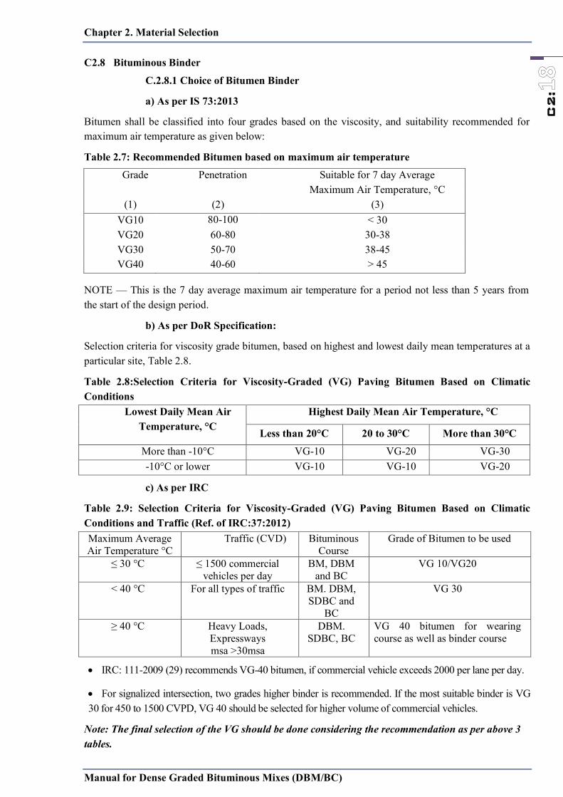
Chapter 2. Material Selection
Manual for Dense Graded Bituminous Mixes (DBM/BC)
C2:
C2.8 Bituminous Binder
C.2.8.1 Choice of Bitumen Binder
a) As per IS 73:2013
Bitumen shall be classified into four grades based on the viscosity, and suitability recommended for maximum air temperature as given below:
Table 2.7: Recommended Bitumen based on maximum air temperature
NOTE — This is the 7 day average maximum air temperature for a period not less than 5 years from the start of the design period.
b) As per DoR Specification:
Selection criteria for viscosity grade bitumen, based on highest and lowest daily mean temperatures at a particular site, Table 2.8.
Table 2.8:Selection Criteria for Viscosity-Graded (VG) Paving Bitumen Based on Climatic Conditions
Lowest Daily Mean Air Temperature, °C
Highest Daily Mean Air Temperature, °C
Less than 20°C 20 to 30°C More than 30°C More than -10°C VG-10 VG-20 VG-30 -10°C or lower VG-10 VG-10 VG-20
c) As per IRC
Table 2.9: Selection Criteria for Viscosity-Graded (VG) Paving Bitumen Based on Climatic Conditions and Traffic (Ref. of IRC:37:2012) Maximum Average Air Temperature °C
Traffic (CVD) Bituminous Course
Grade of Bitumen to be used
≤ 30 °C ≤ 1500 commercial vehicles per day
BM, DBM and BC
VG 10/VG20
< 40 °C For all types of traffic BM. DBM, SDBC and
BC
VG 30
≥ 40 °C Heavy Loads, Expressways msa >30msa
DBM. SDBC, BC
VG 40 bitumen for wearing course as well as binder course
IRC: 111-2009 (29) recommends VG-40 bitumen, if commercial vehicle exceeds 2000 per lane per day.
For signalized intersection, two grades higher binder is recommended. If the most suitable binder is VG 30 for 450 to 1500 CVPD, VG 40 should be selected for higher volume of commercial vehicles.
Note: The final selection of the VG should be done considering the recommendation as per above 3 tables.
Grade Penetration Suitable for 7 day Average Maximum Air Temperature, °C
(1) (2) (3) VG10 80-100 < 30 VG20 60-80 30-38 VG30 50-70 38-45 VG40 40-60 > 45
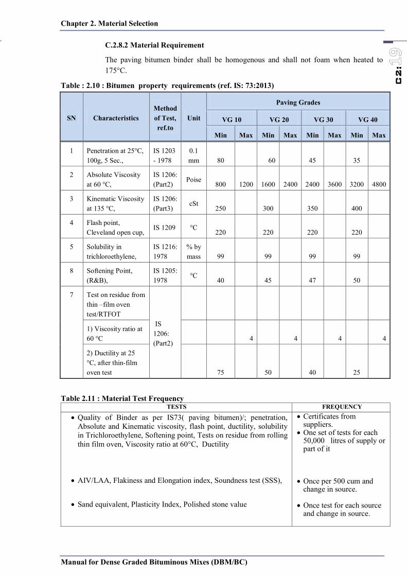
Chapter 2. Material Selection
Manual for Dense Graded Bituminous Mixes (DBM/BC)
C2:
C.2.8.2 Material Requirement
The paving bitumen binder shall be homogenous and shall not foam when heated to 175°C.
Table : 2.10 : Bitumen property requirements (ref. IS: 73:2013)
SN Characteristics Method of Test, ref.to
Unit
Paving Grades
VG 10 VG 20 VG 30 VG 40
Min Max Min Max Min Max Min Max
1 Penetration at 25°C, 100g, 5 Sec.,
IS 1203 - 1978
0.1 mm 80 60 45 35
2 Absolute Viscosity at 60 °C,
IS 1206: (Part2)
Poise 800 1200 1600 2400 2400 3600 3200 4800
3 Kinematic Viscosity at 135 °C,
IS 1206: (Part3)
cSt 250 300 350 400
4 Flash point, Cleveland open cup,
IS 1209 °C 220 220 220 220
5 Solubility in trichloroethylene,
IS 1216: 1978
% by mass 99 99 99 99
8 Softening Point, (R&B),
IS 1205: 1978
°C 40 45 47 50
7 Test on residue from thin –film oven test/RTFOT
IS 1206: (Part2)
1) Viscosity ratio at 60 °C
4 4 4 4
2) Ductility at 25 °C, after thin-film oven test
75 50 40 25
Table 2.11 : Material Test Frequency
TESTS FREQUENCY
Quality of Binder as per IS73( paving bitumen)/; penetration, Absolute and Kinematic viscosity, flash point, ductility, solubility in Trichloroethylene, Softening point, Tests on residue from rolling thin film oven, Viscosity ratio at 60°C, Ductility
AIV/LAA, Flakiness and Elongation index, Soundness test (SSS),
Sand equivalent, Plasticity Index, Polished stone value
Certificates from suppliers.
One set of tests for each 50,000 litres of supply or part of it
Once per 500 cum and
change in source.
Once test for each source and change in source.
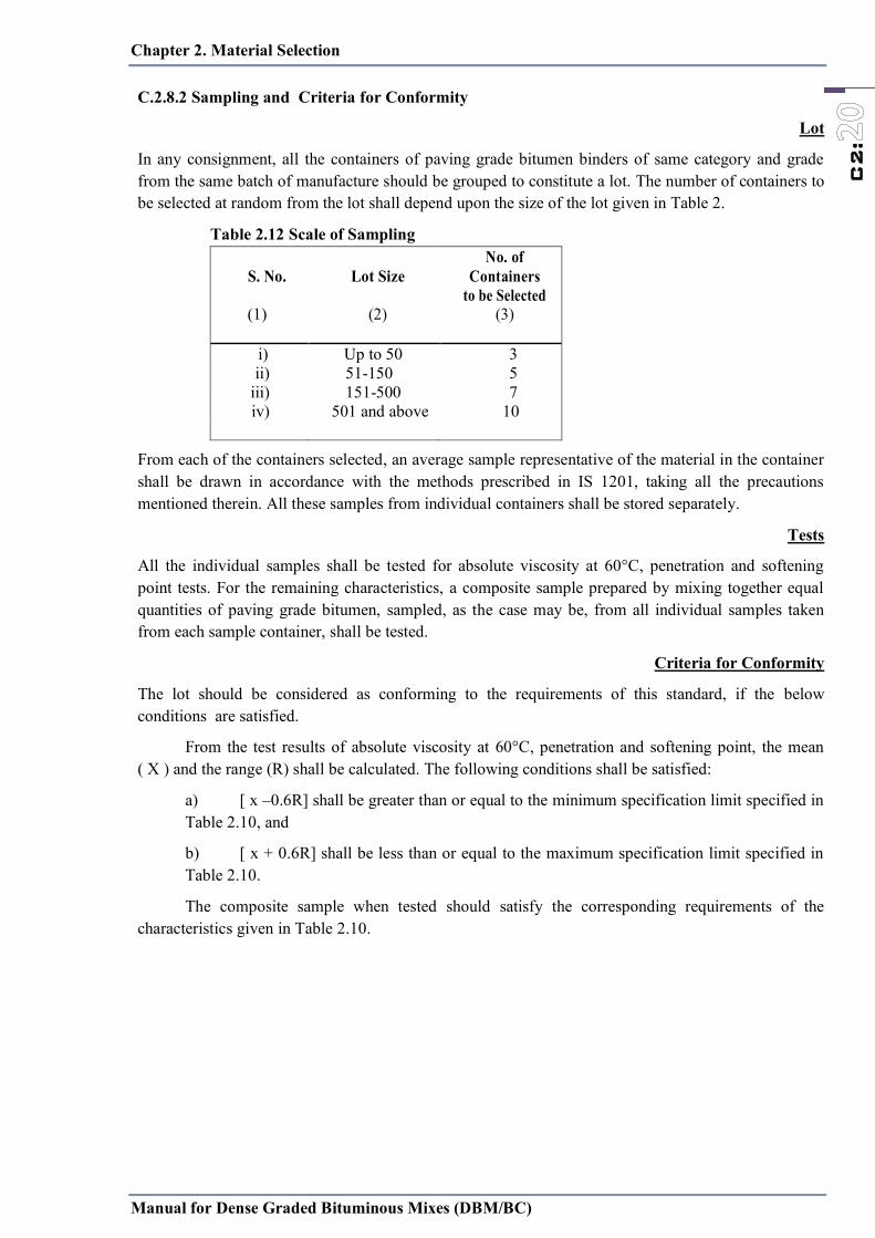
Chapter 2. Material Selection
Manual for Dense Graded Bituminous Mixes (DBM/BC)
C2:
C.2.8.2 Sampling and Criteria for Conformity
Lot
In any consignment, all the containers of paving grade bitumen binders of same category and grade from the same batch of manufacture should be grouped to constitute a lot. The number of containers to be selected at random from the lot shall depend upon the size of the lot given in Table 2.
Table 2.12 Scale of Sampling
S. No. Lot Size No. of
Containers to be Selected
(1) (2) (3)
i) Up to 50 3 ii) 51-150 5
iii) 151-500 7 iv) 501 and above 10
From each of the containers selected, an average sample representative of the material in the container shall be drawn in accordance with the methods prescribed in IS 1201, taking all the precautions mentioned therein. All these samples from individual containers shall be stored separately.
Tests
All the individual samples shall be tested for absolute viscosity at 60°C, penetration and softening point tests. For the remaining characteristics, a composite sample prepared by mixing together equal quantities of paving grade bitumen, sampled, as the case may be, from all individual samples taken from each sample container, shall be tested.
Criteria for Conformity
The lot should be considered as conforming to the requirements of this standard, if the below conditions are satisfied.
From the test results of absolute viscosity at 60°C, penetration and softening point, the mean ( X ) and the range (R) shall be calculated. The following conditions shall be satisfied:
a) [ x –0.6R] shall be greater than or equal to the minimum specification limit specified in Table 2.10, and
b) [ x + 0.6R] shall be less than or equal to the maximum specification limit specified in Table 2.10.
The composite sample when tested should satisfy the corresponding requirements of the characteristics given in Table 2.10.
Chapter 3 Marshall Method of HMA Mix Design
Manual for Dense Graded Bituminous Mixes (DBM/BC)
C3:
C3.1 General
The Marshall method of mix design is for dense graded HMA mixes(DBM/AC). For a single selected aggregate gradation, five different asphalt contents are tested for various volumetric and strength criteria to select the optimum binder content. The test results should always be reported as the average for three compacted, ―identical‖ specimens. The selection of the optimum binder content requires engineering judgment, depending on traffic, climate and experience with the local materials used. In most cases, the optimum binder content should be selected for which the compacted specimens have 4 percent air voids.
Steps for Marshall Method 1.Aggregate and Bitumen Evaluation (Chapter 2); and aggregate proportion by weight 2.Preparation of Marshall Specimens
3.Density and Voids Analysis
4.Marshall Stability and Flow Test
5.Tabulating and Plotting Test Results
6.Optimum Asphalt Content Determination
C3.2 Applicable standards
The Marshall test procedures have been standardized by the American Society for Testing and Materials (ASTM) and by the American Association of State Highway and Transportation Officials (AASHTO). Procedures are given by:
• ASTM D6926, ―Preparation of Bituminous Mixtures Using Marshall Apparatus‖;
• ASTM D6927, ―Standard Test Method for Marshall Stability and Flow of Bituminous Mixtures‖; and
• AASHTO T 245, ―Resistance to Plastic Flow of Bituminous Mixtures Using Marshall Apparatus.‖ AASHTO T 245 agrees with ASTM D6926 except for provisions for a mechanically operated hammer.
The original Marshall method is applicable only to hot mix asphalt paving mixtures containing aggregates with maximum sizes of 25 mm or less. A modified Marshall method has been developed for aggregates with maximum sizes up to 38 mm. Procedures for 6-inch diameter specimen are given by ASTM D5581.
The Marshall method is intended for laboratory design and field control of asphalt hot mix dense-graded paving mixtures. Because the Marshall stability test is empirical in nature, the meaning of the results in terms of estimating relative field behavior is lost when any modification is made to the standard procedures. An example of such modification is preparing specimens from reheated or remolded materials. If reheating cannot be avoided, a correlation should be made to adjust the compactive effort on the reheated mix to match the volumetric properties (such as VMA and % air voids) of the compacted mix which was not reheated.
C3.3 Outline of method
The procedure for the Marshall method starts with the preparation of test specimens. Steps preliminary to specimen preparation are:
• all materials proposed for use meet the physical requirements of the project specifications; • aggregate blend combinations meet the gradation requirements of the project specifications; and
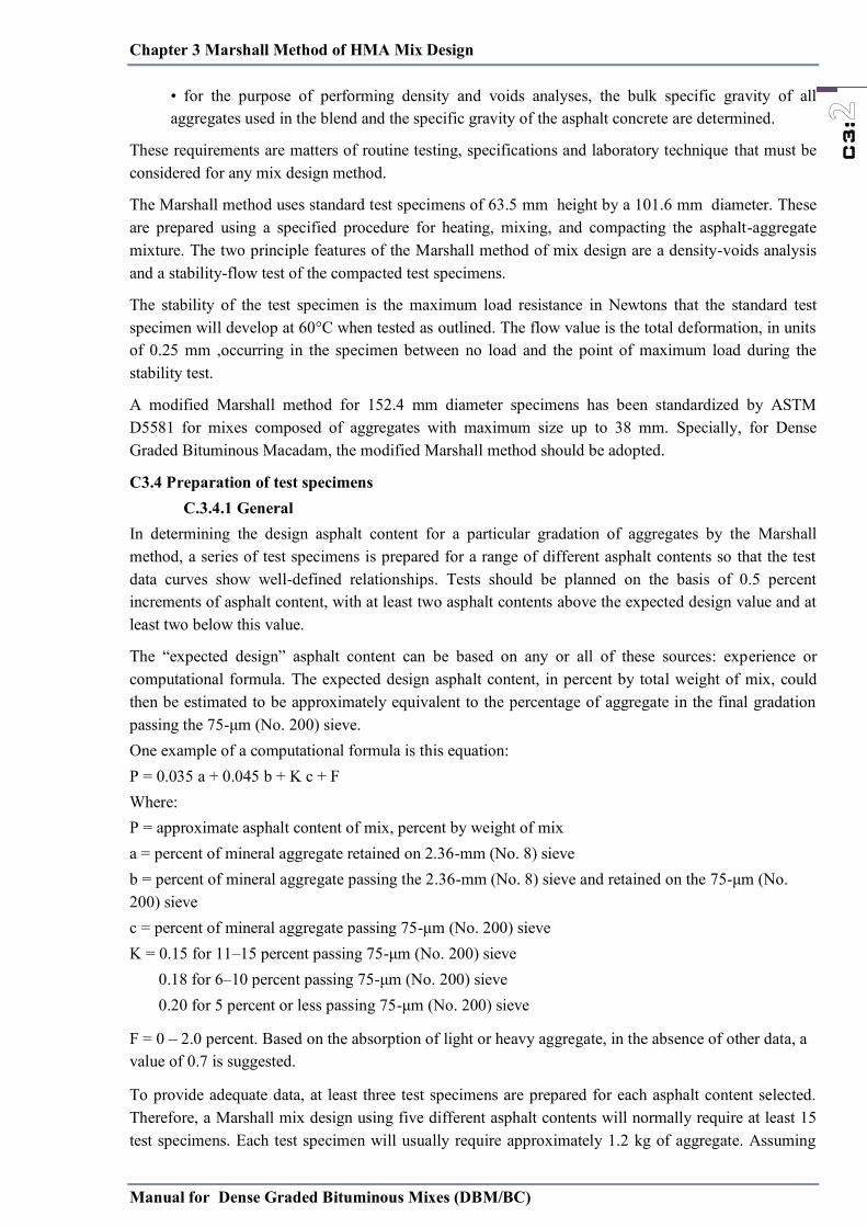
Chapter 3 Marshall Method of HMA Mix Design
Manual for Dense Graded Bituminous Mixes (DBM/BC)
C3:
• for the purpose of performing density and voids analyses, the bulk specific gravity of all aggregates used in the blend and the specific gravity of the asphalt concrete are determined.
These requirements are matters of routine testing, specifications and laboratory technique that must be considered for any mix design method.
The Marshall method uses standard test specimens of 63.5 mm height by a 101.6 mm diameter. These are prepared using a specified procedure for heating, mixing, and compacting the asphalt-aggregate mixture. The two principle features of the Marshall method of mix design are a density-voids analysis and a stability-flow test of the compacted test specimens.
The stability of the test specimen is the maximum load resistance in Newtons that the standard test specimen will develop at 60°C when tested as outlined. The flow value is the total deformation, in units of 0.25 mm ,occurring in the specimen between no load and the point of maximum load during the stability test.
A modified Marshall method for 152.4 mm diameter specimens has been standardized by ASTM D5581 for mixes composed of aggregates with maximum size up to 38 mm. Specially, for Dense Graded Bituminous Macadam, the modified Marshall method should be adopted.
C3.4 Preparation of test specimens C.3.4.1 General
In determining the design asphalt content for a particular gradation of aggregates by the Marshall method, a series of test specimens is prepared for a range of different asphalt contents so that the test data curves show well-defined relationships. Tests should be planned on the basis of 0.5 percent increments of asphalt content, with at least two asphalt contents above the expected design value and at least two below this value.
The ―expected design‖ asphalt content can be based on any or all of these sources: experience or computational formula. The expected design asphalt content, in percent by total weight of mix, could then be estimated to be approximately equivalent to the percentage of aggregate in the final gradation passing the 75-μm (No. 200) sieve. One example of a computational formula is this equation: P = 0.035 a + 0.045 b + K c + F Where: P = approximate asphalt content of mix, percent by weight of mix a = percent of mineral aggregate retained on 2.36-mm (No. 8) sieve b = percent of mineral aggregate passing the 2.36-mm (No. 8) sieve and retained on the 75-μm (No. 200) sieve c = percent of mineral aggregate passing 75-μm (No. 200) sieve K = 0.15 for 11–15 percent passing 75-μm (No. 200) sieve 0.18 for 6–10 percent passing 75-μm (No. 200) sieve 0.20 for 5 percent or less passing 75-μm (No. 200) sieve
F = 0 – 2.0 percent. Based on the absorption of light or heavy aggregate, in the absence of other data, a value of 0.7 is suggested.
To provide adequate data, at least three test specimens are prepared for each asphalt content selected. Therefore, a Marshall mix design using five different asphalt contents will normally require at least 15 test specimens. Each test specimen will usually require approximately 1.2 kg of aggregate. Assuming
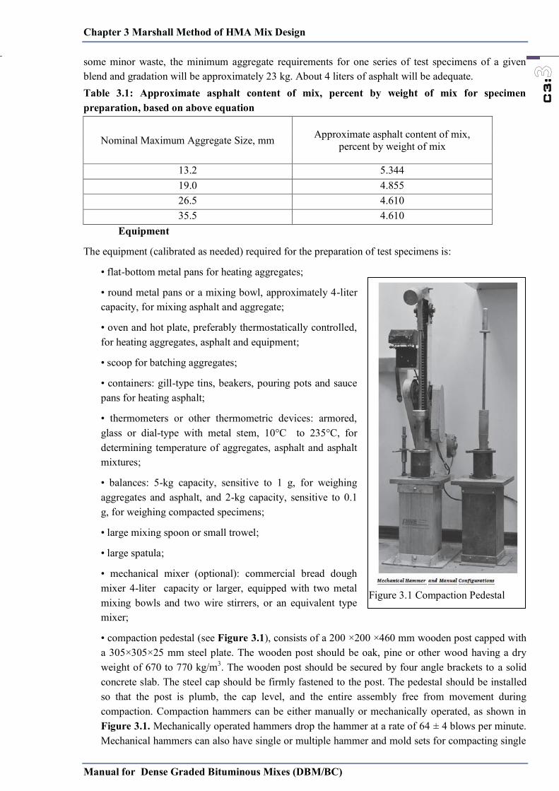
Chapter 3 Marshall Method of HMA Mix Design
Manual for Dense Graded Bituminous Mixes (DBM/BC)
C3:
some minor waste, the minimum aggregate requirements for one series of test specimens of a given blend and gradation will be approximately 23 kg. About 4 liters of asphalt will be adequate. Table 3.1: Approximate asphalt content of mix, percent by weight of mix for specimen preparation, based on above equation
Equipment
The equipment (calibrated as needed) required for the preparation of test specimens is:
• flat-bottom metal pans for heating aggregates;
• round metal pans or a mixing bowl, approximately 4-liter capacity, for mixing asphalt and aggregate;
• oven and hot plate, preferably thermostatically controlled, for heating aggregates, asphalt and equipment;
• scoop for batching aggregates;
• containers: gill-type tins, beakers, pouring pots and sauce pans for heating asphalt;
• thermometers or other thermometric devices: armored, glass or dial-type with metal stem, 10°C to 235°C, for determining temperature of aggregates, asphalt and asphalt mixtures;
• balances: 5-kg capacity, sensitive to 1 g, for weighing aggregates and asphalt, and 2-kg capacity, sensitive to 0.1 g, for weighing compacted specimens;
• large mixing spoon or small trowel;
• large spatula;
• mechanical mixer (optional): commercial bread dough mixer 4-liter capacity or larger, equipped with two metal mixing bowls and two wire stirrers, or an equivalent type mixer;
• compaction pedestal (see Figure 3.1), consists of a 200 ×200 ×460 mm wooden post capped with a 305×305×25 mm steel plate. The wooden post should be oak, pine or other wood having a dry weight of 670 to 770 kg/m3. The wooden post should be secured by four angle brackets to a solid concrete slab. The steel cap should be firmly fastened to the post. The pedestal should be installed so that the post is plumb, the cap level, and the entire assembly free from movement during compaction. Compaction hammers can be either manually or mechanically operated, as shown in Figure 3.1. Mechanically operated hammers drop the hammer at a rate of 64 ± 4 blows per minute. Mechanical hammers can also have single or multiple hammer and mold sets for compacting single
Nominal Maximum Aggregate Size, mm Approximate asphalt content of mix, percent by weight of mix
13.2 5.344 19.0 4.855 26.5 4.610 35.5 4.610
Figure 3.1 Compaction Pedestal
Chapter 3 Marshall Method of HMA Mix Design
Manual for Dense Graded Bituminous Mixes (DBM/BC)
C3:
or multiple specimens at a time. Some mechanically operated hammers are designed with a rotating base mechanism which rotates at 18 to 30 revolutions per minute;
• compaction mold, consisting of a base plate, forming mold and collar extension. The forming mold has an inside diameter of 101.6 mm and a height of approximately 75 mm; the base plate and collar extension are designed to be interchangeable with either end of the forming mold. ASTM D5581 references a 154.2-mm mold with a 114.3-mm height for use with aggregate up to 38mm NMAS (for modified Marshall Test) and should conform to requirements of ASTM D6926;
• compaction hammer, consisting of a flat, circular tamping face, 98.4 mm in diameter and equipped with a 4.5-kg weight constructed to obtain a specified 457 mm height of drop, should conform to requirements of ASTM D6926;
• mold holder, consisting of spring-tension device designed to hold compaction mold centered in place on the compaction pedestal, should conform to requirements of ASTM D6926;
• paper disks, 100 mm;
• steel specimen extractor, in the form of a jack and a disk with a diameter not less than 100 mm and 13 mm thick for extruding compacted specimen form mold.
The steel specimen extractor for the 6-inch mold is 151.5 to 152.5 mm (5.950 to 5.990 in.) in diameter and 13 mm (0.5 in.) thick;
• welders’ gloves, for handling hot equipment. Rubber gloves for removing specimens from water bath; and
• marking crayons, for identifying test specimens.
C3.5 Preparation of test specimens
These steps are recommended for preparing Marshall test specimens.
(a) Number of specimens—prepare at least three specimens for each combination of aggregates and binder content.
(b) Preparation of aggregates—dry aggregates to constant weight at 105°C to 110°C and separate the aggregates by dry sieving into the desired size fractions. These size fractions are recommended:
• 38.0-25.0 mm • 25.0 to 19.0 mm • 19.0 to 13.2 mm • 13.2 to 4.75 mm • 4.75 to 2.36 mm (No. 4 to No. 8) • Passing 2.36 mm (No. 8)
Aggregate batching and mix sample preparation
There are no AASHTO, ASTM or other widely accepted standards for the batching of aggregates for asphalt mix design. Many variations exist and are specified by some agencies. An important part of any batching procedure is to completely dry the aggregates before beginning. Aggregate samples from the plant or quarry may come to the lab saturated with moisture. Fine aggregate stockpiles tend to absorb a higher percentage of moisture than coarser aggregate. Without completely drying the aggregate first, the absorbed moisture will increase the aggregate weight, resulting in inaccurate material proportions in the batch.
Prior to batching samples for the mix design, gradations should be performed on each material submitted. Aggregate material submitted for mix design should be accompanied with production test results. Submitted materials should then be compared with production test results to assure the materials
Chapter 3 Marshall Method of HMA Mix Design
Manual for Dense Graded Bituminous Mixes (DBM/BC)
C3:
submitted for mix design are representative of the materials that will be used in the project. Softer aggregates tend to degrade more during the production process than harder aggregates, often resulting in a finer gradation than the aggregate sample used for mix design. It can be taken account by determining the extent of the additional fines created during production and making a corresponding adjustment to the aggregate batch for mix design. Performing this adjustment may help avoid the drop in air voids and VMA often seen in plant mixes versus laboratory mixes.
Therefore, a careful comparison of gradations and all other specified characteristics should be made prior to conducting a mix design. Conducting a mixture design using aggregate that does not meet a project specification or is not representative of field-produced material is of little use. There are many different methods that can be utilized to prepare aggregate samples for mixture testing. They can range from very accurate and time-consuming to relatively quick but with less accuracy. Accurately prepared specimens that are representative of the final aggregate blend produced by the mixing plant will give the most reliable mixture design data. The mix designer should use the most accurate method practical that obtains representative and reproducible results and specimen with minimal variability. Many agencies specify certain methodologies for specimen preparation.
The Asphalt Institute recommends that in order to achieve the highest level of accuracy and repeatability of laboratory-prepared specimens, individual samples should be batched rather than multiple specimens being batched, mixed and then divided into individual samples.
Method 1—Partial fractionation of individual stockpiles
The smallest practical sieve for a large capacity tray-type shaker is usually 0.15 or 0.075 mm. Fractionate each stockpile sample on each specified sieve, leaving the entire amount passing the smallest sieve as one fraction to be added during batching. The pan material using this method becomes all of the material that passes the 0.075 mm sieve (or whatever sieve is on the bottom of the stack). Large capacity, tray-type mechanical shakers have the capacity to fractionate samples up to 23 or more kg. Care should be taken to prevent overloading of sieve screens. The amount allowed on each sieve is dependent on the nominal maximum aggregate size (NMAS), as outlined in Table 2.5.
A typical batching sheet for one stockpile would appear as shown in Table 3.2 using the following equations, and must be repeated for each stockpile of aggregate to be used:
Determine the grams needed from each aggregate stockpile:
Stockpile grams needed = Total specimen size x bin split % / 100
Determine the percent retained on each sieve:
% Retained on a sieve = % Passing the next larger sieve − % Passing the sieve
Determine the amount to be contributed from each individual sieve fraction:
Grams of each fraction required = % Retained x Grams Needed / 100
Care must be taken to assure that the large amounts of pan material shown are uniformly blended and added to the batch sample.

Cha
pter
3 M
arsh
all M
etho
d of
HM
A M
ix D
esig
n M
anua
l for
Den
se G
rade
d B
itum
inou
s Mix
es (D
BM
/BC
)
C3:
Tab
le :
3.2
Sam
ple
of M
etho
d 1
Tota
l Spe
cim
en S
ize
= 50
00 g
ms
Size
19
-13.
2mm
13
.2-4
.75m
m
Fine
(pas
sing
2.3
6mm
)
Bin
Sp
lit %
25
45
30
G
ram
s ne
eded
12
50
2250
15
00
%
Pas
s %
R
etai
ned
Indi
vidu
al
Wt.,
gm
Cum
ulat
ive
% P
ass
%
Ret
aine
d In
divi
dual
W
t.,gm
C
umul
ativ
e %
Pas
s %
R
etai
ned
Indi
vidu
al
Wt.,
gm
Cum
ulat
ive
19
90
10
125.
0 12
5.0
100
0 0.
0 0.
0 10
0 0
0.0
0.0
13.2
40
50
62
5.0
750.
0 90
10
22
5.0
225.
0 10
0 0
0.0
0.0
9.5
25
15
187.
5 93
7.5
40
50
1125
.0
1350
.0
100
0 0.
0 0.
0 4.
75
0 25
31
2.5
1250
.0
0 40
90
0.0
2250
.0
90
10
150.
0 15
0.0
2.36
0
0 0.
0 12
50.0
0
0 0.
0 22
50.0
75
15
22
5.0
375.
0 1.
18
0 0
0.0
1250
.0
0 0
0.0
2250
.0
55
20
300.
0 67
5.0
Pan
0 0
0.0
1250
.0
0 0
0.0
2250
.0
0 55
82
5.0
1500
.0
# B
in S
plit
shou
ld b
e su
ch th
at th
e bl
ende
d m
ix o
f agg
rega
te sh
ould
satis
fy th
e gr
adia
tion
requ
irem
ent a
s per
Tab
le 2
.5.
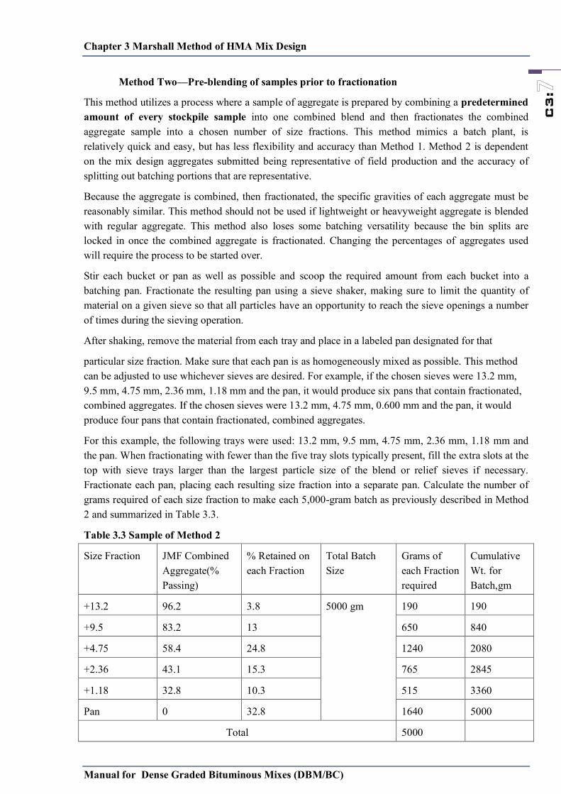
Chapter 3 Marshall Method of HMA Mix Design
Manual for Dense Graded Bituminous Mixes (DBM/BC)
C3:
Method Two—Pre-blending of samples prior to fractionation
This method utilizes a process where a sample of aggregate is prepared by combining a predetermined amount of every stockpile sample into one combined blend and then fractionates the combined aggregate sample into a chosen number of size fractions. This method mimics a batch plant, is relatively quick and easy, but has less flexibility and accuracy than Method 1. Method 2 is dependent on the mix design aggregates submitted being representative of field production and the accuracy of splitting out batching portions that are representative.
Because the aggregate is combined, then fractionated, the specific gravities of each aggregate must be reasonably similar. This method should not be used if lightweight or heavyweight aggregate is blended with regular aggregate. This method also loses some batching versatility because the bin splits are locked in once the combined aggregate is fractionated. Changing the percentages of aggregates used will require the process to be started over.
Stir each bucket or pan as well as possible and scoop the required amount from each bucket into a batching pan. Fractionate the resulting pan using a sieve shaker, making sure to limit the quantity of material on a given sieve so that all particles have an opportunity to reach the sieve openings a number of times during the sieving operation.
After shaking, remove the material from each tray and place in a labeled pan designated for that
particular size fraction. Make sure that each pan is as homogeneously mixed as possible. This method can be adjusted to use whichever sieves are desired. For example, if the chosen sieves were 13.2 mm, 9.5 mm, 4.75 mm, 2.36 mm, 1.18 mm and the pan, it would produce six pans that contain fractionated, combined aggregates. If the chosen sieves were 13.2 mm, 4.75 mm, 0.600 mm and the pan, it would produce four pans that contain fractionated, combined aggregates.
For this example, the following trays were used: 13.2 mm, 9.5 mm, 4.75 mm, 2.36 mm, 1.18 mm and the pan. When fractionating with fewer than the five tray slots typically present, fill the extra slots at the top with sieve trays larger than the largest particle size of the blend or relief sieves if necessary. Fractionate each pan, placing each resulting size fraction into a separate pan. Calculate the number of grams required of each size fraction to make each 5,000-gram batch as previously described in Method 2 and summarized in Table 3.3.
Table 3.3 Sample of Method 2
Size Fraction JMF Combined Aggregate(% Passing)
% Retained on each Fraction
Total Batch Size
Grams of each Fraction required
Cumulative Wt. for Batch,gm
+13.2 96.2 3.8 5000 gm 190 190
+9.5 83.2 13 650 840
+4.75 58.4 24.8 1240 2080
+2.36 43.1 15.3 765 2845
+1.18 32.8 10.3 515 3360
Pan 0 32.8 1640 5000
Total 5000
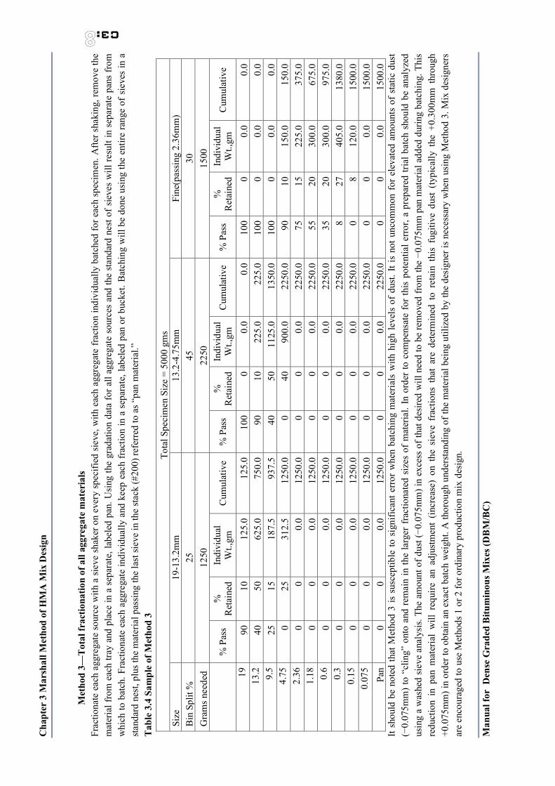
Cha
pter
3 M
arsh
all M
etho
d of
HM
A M
ix D
esig
n M
anua
l for
Den
se G
rade
d B
itum
inou
s Mix
es (D
BM
/BC
)
C3:
Met
hod
3—T
otal
frac
tiona
tion
of a
ll ag
greg
ate
mat
eria
ls
Frac
tiona
te e
ach
aggr
egat
e so
urce
with
a s
ieve
shak
er o
n ev
ery
spec
ified
siev
e, w
ith e
ach
aggr
egat
e fr
actio
n in
divi
dual
ly b
atch
ed fo
r eac
h sp
ecim
en. A
fter s
haki
ng, r
emov
e th
e m
ater
ial f
rom
eac
h tra
y an
d pl
ace
in a
sep
arat
e, la
bele
d pa
n. U
sing
the
grad
atio
n da
ta fo
r all
aggr
egat
e so
urce
s an
d th
e sta
ndar
d ne
st of
sie
ves
will
resu
lt in
sep
arat
e pa
ns fr
om
whi
ch to
bat
ch. F
ract
iona
te e
ach
aggr
egat
e in
divi
dual
ly a
nd k
eep
each
frac
tion
in a
sep
arat
e, la
bele
d pa
n or
buc
ket.
Bat
chin
g w
ill b
e do
ne u
sing
the
entir
e ra
nge
of s
ieve
s in
a
stand
ard
nest
, plu
s the
mat
eria
l pas
sing
the
last
siev
e in
the
stack
(#20
0) re
ferre
d to
as ―
pan
mat
eria
l.‖
Tab
le 3
.4 S
ampl
e of
Met
hod
3 To
tal S
peci
men
Siz
e =
5000
gm
s Si
ze
19-1
3.2m
m
13.2
-4.7
5mm
Fi
ne(p
assi
ng 2
.36m
m)
Bin
Spl
it %
25
45
30
G
ram
s nee
ded
1250
22
50
1500
%
Pas
s %
R
etai
ned
Indi
vidu
al
Wt.,
gm
Cum
ulat
ive
% P
ass
%
Ret
aine
d In
divi
dual
W
t.,gm
C
umul
ativ
e %
Pas
s %
R
etai
ned
Indi
vidu
al
Wt.,
gm
Cum
ulat
ive
19
90
10
125.
0 12
5.0
100
0 0.
0 0.
0 10
0 0
0.0
0.0
13.2
40
50
62
5.0
750.
0 90
10
22
5.0
225.
0 10
0 0
0.0
0.0
9.5
25
15
187.
5 93
7.5
40
50
1125
.0
1350
.0
100
0 0.
0 0.
0 4.
75
0 25
31
2.5
1250
.0
0 40
90
0.0
2250
.0
90
10
150.
0 15
0.0
2.36
0
0 0.
0 12
50.0
0
0 0.
0 22
50.0
75
15
22
5.0
375.
0 1.
18
0 0
0.0
1250
.0
0 0
0.0
2250
.0
55
20
300.
0 67
5.0
0.6
0 0
0.0
1250
.0
0 0
0.0
2250
.0
35
20
300.
0 97
5.0
0.3
0 0
0.0
1250
.0
0 0
0.0
2250
.0
8 27
40
5.0
1380
.0
0.15
0
0 0.
0 12
50.0
0
0 0.
0 22
50.0
0
8 12
0.0
1500
.0
0.07
5 0
0 0.
0 12
50.0
0
0 0.
0 22
50.0
0
0 0.
0 15
00.0
Pa
n 0
0 0.
0 12
50.0
0
0 0.
0 22
50.0
0
0 0.
0 15
00.0
It
shou
ld b
e no
ted
that
Met
hod
3 is
susc
eptib
le to
sig
nific
ant e
rror
whe
n ba
tchi
ng m
ater
ials
with
hig
h le
vels
of
dust.
It is
not
unc
omm
on f
or e
leva
ted
amou
nts
of s
tatic
dus
t (−
0.07
5mm
) to
―clin
g‖ o
nto
and
rem
ain
in th
e la
rger
fra
ctio
nate
d si
zes
of m
ater
ial.
In o
rder
to c
ompe
nsat
e fo
r thi
s po
tent
ial e
rror,
a pr
epar
ed tr
ial b
atch
sho
uld
be a
naly
zed
usin
g a
was
hed
sieve
ana
lysi
s. Th
e am
ount
of d
ust (
−0.0
75m
m) i
n ex
cess
of t
hat d
esire
d w
ill n
eed
to b
e re
mov
ed fr
om th
e −0
.075
mm
pan
mat
eria
l add
ed d
urin
g ba
tchi
ng. T
his
redu
ctio
n in
pan
mat
eria
l w
ill r
equi
re a
n ad
justm
ent
(incr
ease
) on
the
sie
ve f
ract
ions
tha
t ar
e de
term
ined
to
reta
in t
his
fugi
tive
dust
(typi
cally
the
+0.
300m
m t
hrou
gh
+0.0
75m
m) i
n or
der t
o ob
tain
an
exac
t bat
ch w
eigh
t. A
thor
ough
und
ersta
ndin
g of
the
mat
eria
l bei
ng u
tiliz
ed b
y th
e de
sign
er is
nec
essa
ry w
hen
usin
g M
etho
d 3.
Mix
des
igne
rs
are
enco
urag
ed to
use
Met
hods
1 o
r 2 fo
r ord
inar
y pr
oduc
tion
mix
des
ign.

Chapter 3 Marshall Method of HMA Mix Design
Manual for Dense Graded Bituminous Mixes (DBM/BC)
C3:
Table 3.5: Approximate Batching Proportion#
Nominal Maximum Aggregate Size,mm
Approximate Batching Proportion, %
Aggregate passing the size
38-25mm 25-19mm 19-13.2mm 13.2-4.75mm Fine(passing
2.36mm)
13.2 - - - 47-59 35-47
19 - - 16-32 45-56 22-28
26.5 - 16-27 24-33 16-33 22-27
35.5 11-22 27-43 - 16-27 27-32
# All individual case should be batched to meet the table 2.5
The typical allowable range for dust to binder ratio (P0.075/Pbe) is 0.6–1.2, with the following exceptions: for coarse-graded mixes whose gradation plots below the Primary Control Sieve (PCS) on a 0.45 power chart, the allowable range may be increased to 0.8–1.6.
In general, this property addresses the workability of asphalt mixtures. A low P0.075/Pbe often results in a tender mix, which lacks cohesion and is difficult to compact in the field because it tends to move laterally under the roller. Mixes tend to stiffen as the P0.075 increases, but too much will also result in a tender mix. A mix with a high P0.075/Pbe will often exhibit a multitude of small stress cracks during the compaction process, called check-cracking. This property is usually calculated for dense-graded mixes only.
(c) Determination of mixing and compaction temperature—the temperature to which the asphalt must be heated to produce viscosities of 170 ± 20 centistokes kinematic and 280 ± 30 centistokes kinematic should be established as the mixing temperature and compaction temperatures, respectively. These temperatures can be estimated from a plot of the viscosity (log-log centistokes scale) versus temperature relationship for the asphalt concrete to be used. An example plot is shown in Figure 3.2
Figure 3.2 Determination of Mixing and Compaction Temperatures
0.1
1
10
100 110 120 130 140 150 160 170 180 190 200
Visc
osity
,Pa-
s
Temperature, °C
Mixing and Compaction Temperature Chart
Compaction Range
Mixing Range
Mixing Temperature
Compaction Temperature
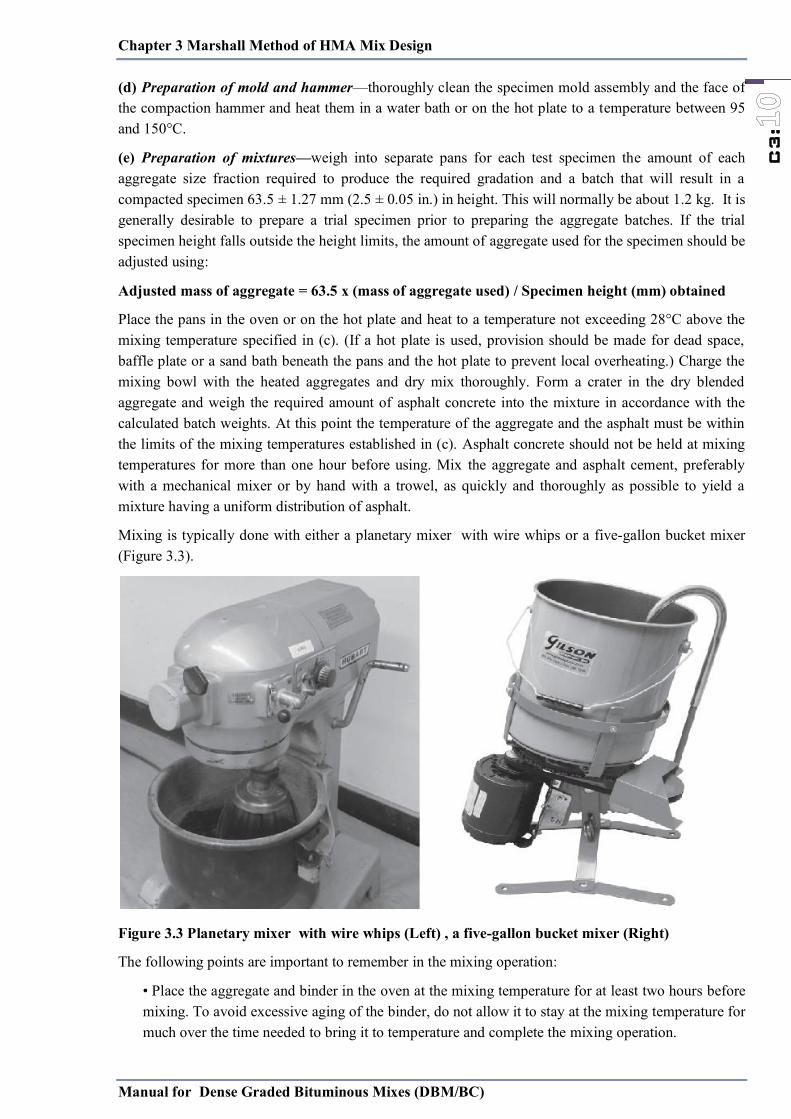
Chapter 3 Marshall Method of HMA Mix Design
Manual for Dense Graded Bituminous Mixes (DBM/BC)
C3:
(d) Preparation of mold and hammer—thoroughly clean the specimen mold assembly and the face of the compaction hammer and heat them in a water bath or on the hot plate to a temperature between 95 and 150°C.
(e) Preparation of mixtures—weigh into separate pans for each test specimen the amount of each aggregate size fraction required to produce the required gradation and a batch that will result in a compacted specimen 63.5 ± 1.27 mm (2.5 ± 0.05 in.) in height. This will normally be about 1.2 kg. It is generally desirable to prepare a trial specimen prior to preparing the aggregate batches. If the trial specimen height falls outside the height limits, the amount of aggregate used for the specimen should be adjusted using:
Adjusted mass of aggregate = 63.5 x (mass of aggregate used) / Specimen height (mm) obtained
Place the pans in the oven or on the hot plate and heat to a temperature not exceeding 28°C above the mixing temperature specified in (c). (If a hot plate is used, provision should be made for dead space, baffle plate or a sand bath beneath the pans and the hot plate to prevent local overheating.) Charge the mixing bowl with the heated aggregates and dry mix thoroughly. Form a crater in the dry blended aggregate and weigh the required amount of asphalt concrete into the mixture in accordance with the calculated batch weights. At this point the temperature of the aggregate and the asphalt must be within the limits of the mixing temperatures established in (c). Asphalt concrete should not be held at mixing temperatures for more than one hour before using. Mix the aggregate and asphalt cement, preferably with a mechanical mixer or by hand with a trowel, as quickly and thoroughly as possible to yield a mixture having a uniform distribution of asphalt.
Mixing is typically done with either a planetary mixer with wire whips or a five-gallon bucket mixer (Figure 3.3).
Figure 3.3 Planetary mixer with wire whips (Left) , a five-gallon bucket mixer (Right)
The following points are important to remember in the mixing operation:
• Place the aggregate and binder in the oven at the mixing temperature for at least two hours before mixing. To avoid excessive aging of the binder, do not allow it to stay at the mixing temperature for much over the time needed to bring it to temperature and complete the mixing operation.
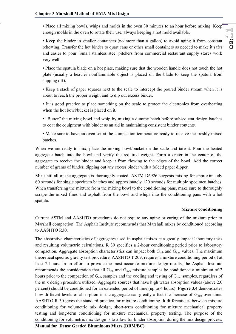
Chapter 3 Marshall Method of HMA Mix Design
Manual for Dense Graded Bituminous Mixes (DBM/BC)
C3:
• Place all mixing bowls, whips and molds in the oven 30 minutes to an hour before mixing. Keep enough molds in the oven to rotate their use, always keeping a hot mold available.
• Keep the binder in smaller containers (no more than a gallon) to avoid aging it from constant reheating. Transfer the hot binder to quart cans or other small containers as needed to make it safer and easier to pour. Small stainless steel pitchers from commercial restaurant supply stores work very well.
• Place the spatula blade on a hot plate, making sure that the wooden handle does not touch the hot plate (usually a heavier nonflammable object is placed on the blade to keep the spatula from slipping off).
• Keep a stack of paper squares next to the scale to intercept the poured binder stream when it is about to reach the proper weight and to dip out excess binder.
• It is good practice to place something on the scale to protect the electronics from overheating when the hot bowl/bucket is placed on it.
• ―Butter‖ the mixing bowl and whip by mixing a dummy batch before subsequent design batches to coat the equipment with binder as an aid in maintaining consistent binder contents.
• Make sure to have an oven set at the compaction temperature ready to receive the freshly mixed batches.
When we are ready to mix, place the mixing bowl/bucket on the scale and tare it. Pour the heated aggregate batch into the bowl and verify the required weight. Form a crater in the center of the aggregate to receive the binder and keep it from flowing to the edges of the bowl. Add the correct number of grams of binder, dipping out any excess binder with a folded paper dipper.
Mix until all of the aggregate is thoroughly coated. ASTM D6926 suggests mixing for approximately 60 seconds for single specimen batches and approximately 120 seconds for multiple specimen batches. When transferring the mixture from the mixing bowl to the conditioning pans, make sure to thoroughly scrape the mixed fines and asphalt from the bowl and whips into the conditioning pans with a hot spatula.
Mixture conditioning
Current ASTM and AASHTO procedures do not require any aging or curing of the mixture prior to Marshall compaction. The Asphalt Institute recommends that Marshall mixes be conditioned according to AASHTO R30.
The absorptive characteristics of aggregates used in asphalt mixes can greatly impact laboratory tests and resulting volumetric calculations. R 30 specifies a 2-hour conditioning period prior to laboratory compaction. Aggregate absorption characteristics can impact both Gmb and Gmm values. The maximum theoretical specific gravity test procedure, AASHTO T 209, requires a mixture conditioning period of at least 2 hours. In an effort to provide the most accurate mixture design results, the Asphalt Institute recommends the consideration that all Gmb and Gmm mixture samples be conditioned a minimum of 2 hours prior to the compaction of Gmb samples and the cooling and testing of Gmm samples, regardless of the mix design procedure utilized. Aggregate sources that have high water absorption values (above 2.0 percent) should be conditioned for an extended period of time (up to 4 hours). Figure 3.4 demonstrates how different levels of absorption in the aggregate can greatly affect the increase of Gmm over time. AASHTO R 30 gives the standard practice for mixture conditioning. It differentiates between mixture conditioning for volumetric mix design, short-term conditioning for mixture mechanical property testing and long-term conditioning for mixture mechanical property testing. The purpose of the conditioning for volumetric mix design is to allow for binder absorption during the mix design process.
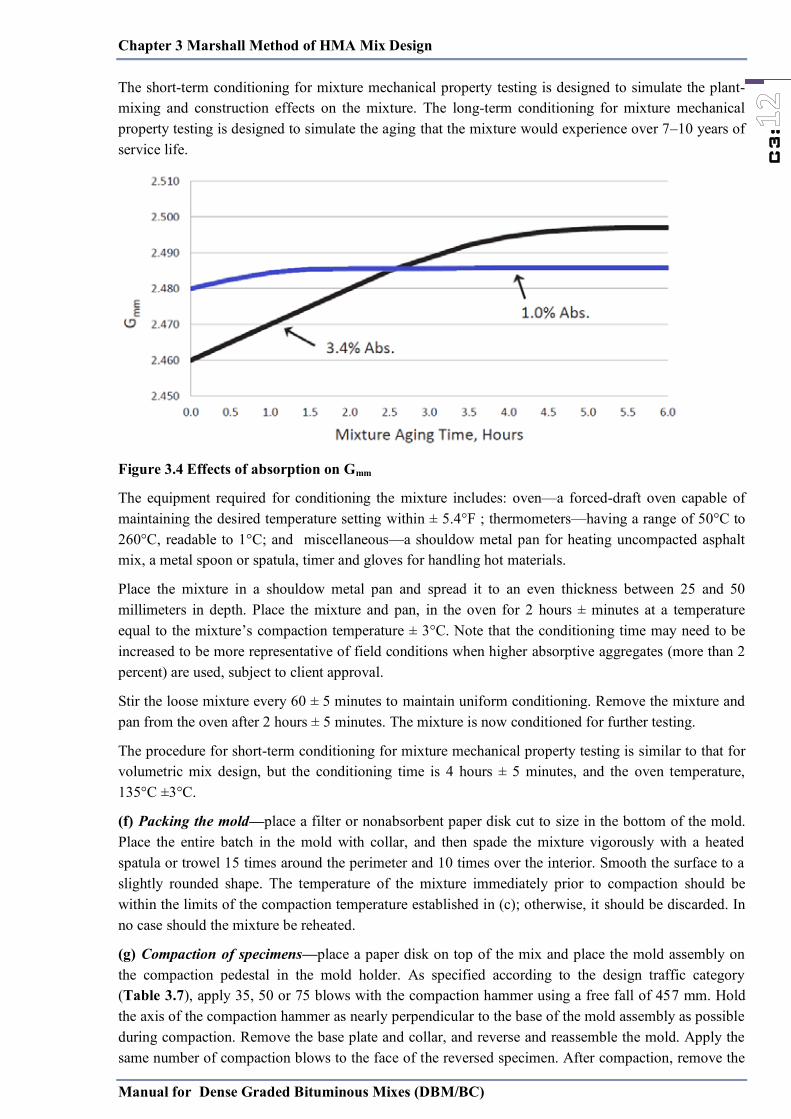
Chapter 3 Marshall Method of HMA Mix Design
Manual for Dense Graded Bituminous Mixes (DBM/BC)
C3:
The short-term conditioning for mixture mechanical property testing is designed to simulate the plant-mixing and construction effects on the mixture. The long-term conditioning for mixture mechanical property testing is designed to simulate the aging that the mixture would experience over 7–10 years of service life.
Figure 3.4 Effects of absorption on Gmm
The equipment required for conditioning the mixture includes: oven—a forced-draft oven capable of maintaining the desired temperature setting within ± 5.4°F ; thermometers—having a range of 50°C to 260°C, readable to 1°C; and miscellaneous—a shouldow metal pan for heating uncompacted asphalt mix, a metal spoon or spatula, timer and gloves for handling hot materials.
Place the mixture in a shouldow metal pan and spread it to an even thickness between 25 and 50 millimeters in depth. Place the mixture and pan, in the oven for 2 hours ± minutes at a temperature equal to the mixture’s compaction temperature ± 3°C. Note that the conditioning time may need to be increased to be more representative of field conditions when higher absorptive aggregates (more than 2 percent) are used, subject to client approval.
Stir the loose mixture every 60 ± 5 minutes to maintain uniform conditioning. Remove the mixture and pan from the oven after 2 hours ± 5 minutes. The mixture is now conditioned for further testing.
The procedure for short-term conditioning for mixture mechanical property testing is similar to that for volumetric mix design, but the conditioning time is 4 hours ± 5 minutes, and the oven temperature, 135°C ±3°C.
(f) Packing the mold—place a filter or nonabsorbent paper disk cut to size in the bottom of the mold. Place the entire batch in the mold with collar, and then spade the mixture vigorously with a heated spatula or trowel 15 times around the perimeter and 10 times over the interior. Smooth the surface to a slightly rounded shape. The temperature of the mixture immediately prior to compaction should be within the limits of the compaction temperature established in (c); otherwise, it should be discarded. In no case should the mixture be reheated.
(g) Compaction of specimens—place a paper disk on top of the mix and place the mold assembly on the compaction pedestal in the mold holder. As specified according to the design traffic category (Table 3.7), apply 35, 50 or 75 blows with the compaction hammer using a free fall of 457 mm. Hold the axis of the compaction hammer as nearly perpendicular to the base of the mold assembly as possible during compaction. Remove the base plate and collar, and reverse and reassemble the mold. Apply the same number of compaction blows to the face of the reversed specimen. After compaction, remove the
Chapter 3 Marshall Method of HMA Mix Design
Manual for Dense Graded Bituminous Mixes (DBM/BC)
C3:
base plate and the paper disks and allow the specimen to cool at room temperature until no deformation will result when removing it from the mold. When more rapid cooling is desired, electric fans may be used, but not water unless the specimen is in a plastic bag. Remove the specimen from the mold by means of an extrusion jack or other compression device, and then place on a smooth, level surface until ready for testing. Normally, specimens are allowed to cool overnight.
Correlation of the manually and mechanically operated hammers
There is a tendency for manually operated hammers to yield a higher specimen density than mechanically operated hammers. It has been theorized that a slight kneading effect takes place when the manually operated hammer is dropped at a slight angle from the true-vertical action of the automated hammers. If variations of the standard manual Marshall hammer (e.g., mechanical lift, slanted face and rotating base) are used, correlations with the standard Marshall compaction procedure must be made. This is equally the case if mix samples are reheated before compaction.
The Asphalt Institute recommends using only mechanical hammers for mix design and field verification. The Asphalt Institute also recommends that the asphalt pavement owner establish a governing compactor which establishes the job mix formula parameters and resulting construction tolerances.
The Asphalt Institute further recommends that all laboratory compactors utilized in the quality control, acceptance or assurance of field constructed pavements be correlated to the governing compactor utilized in the mixture design approved by the pavement owner.
An example of such a correlation is adjusting the number of blows to result in the same volumetric properties. Using the same mix and compaction temperature as in the mix design, compact triplicate specimens at five different blow counts.
As a minimum, specimens should be compacted at the mix design number of blows, ± 5 blows and ± 10 blows. Draw a ―number of blows vs. Gmb curve‖ and determine the number of blows required to get the same Gmb obtained by the governing compactor used in the mix design. This new correlated blow count should be used for all further testing when utilizing this correlated compactor. The range of blow counts must be large enough to include the results of the governing compactor without extrapolation of the correlation curve. An example of a correlation curve is shown below in Figure 3.5.
Figure 3.5 Compactor correlation curve
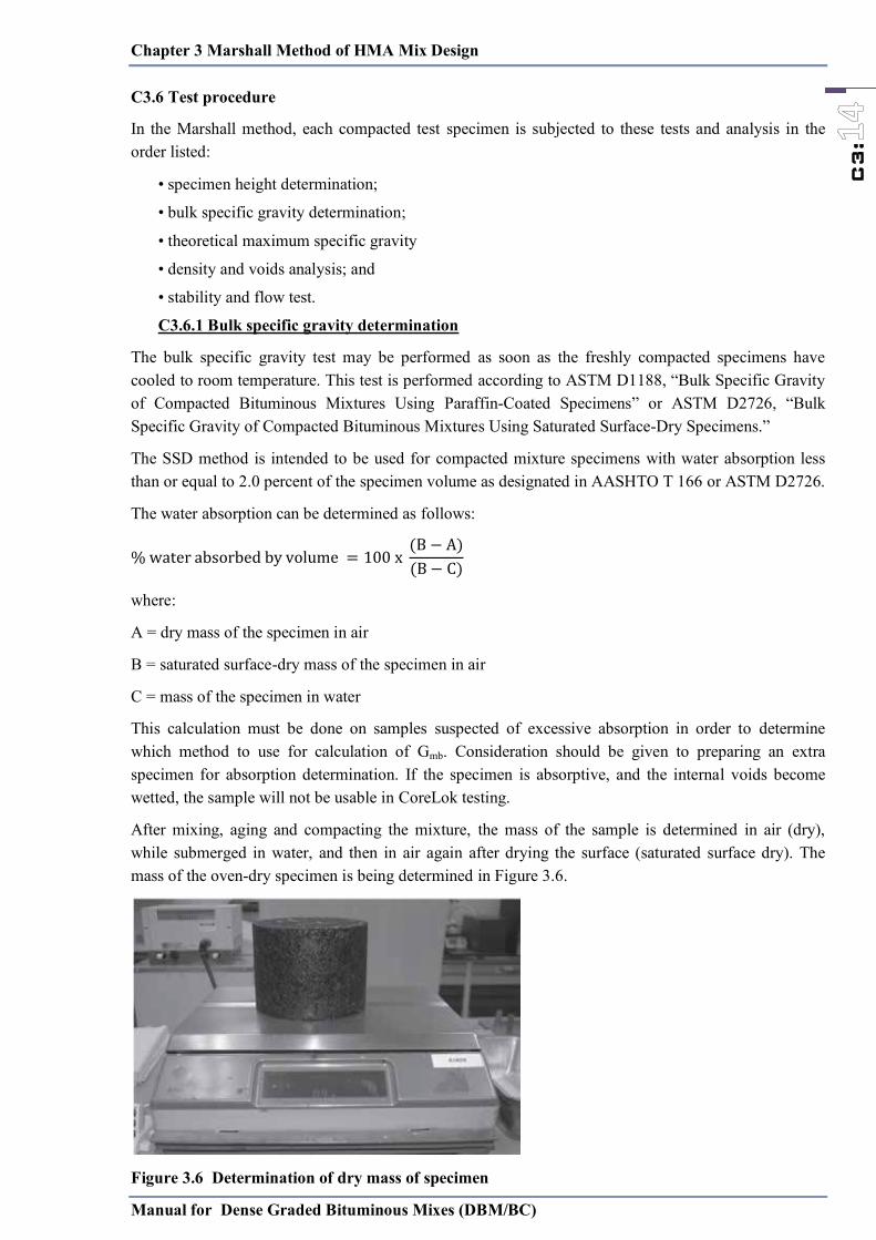
Chapter 3 Marshall Method of HMA Mix Design
Manual for Dense Graded Bituminous Mixes (DBM/BC)
C3:
C3.6 Test procedure
In the Marshall method, each compacted test specimen is subjected to these tests and analysis in the order listed:
• specimen height determination;
• bulk specific gravity determination;
• theoretical maximum specific gravity
• density and voids analysis; and
• stability and flow test.
C3.6.1 Bulk specific gravity determination
The bulk specific gravity test may be performed as soon as the freshly compacted specimens have cooled to room temperature. This test is performed according to ASTM D1188, ―Bulk Specific Gravity of Compacted Bituminous Mixtures Using Paraffin-Coated Specimens‖ or ASTM D2726, ―Bulk Specific Gravity of Compacted Bituminous Mixtures Using Saturated Surface-Dry Specimens.‖
The SSD method is intended to be used for compacted mixture specimens with water absorption less than or equal to 2.0 percent of the specimen volume as designated in AASHTO T 166 or ASTM D2726.
The water absorption can be determined as follows:
−−
where:
A = dry mass of the specimen in air
B = saturated surface-dry mass of the specimen in air
C = mass of the specimen in water
This calculation must be done on samples suspected of excessive absorption in order to determine which method to use for calculation of Gmb. Consideration should be given to preparing an extra specimen for absorption determination. If the specimen is absorptive, and the internal voids become wetted, the sample will not be usable in CoreLok testing.
After mixing, aging and compacting the mixture, the mass of the sample is determined in air (dry), while submerged in water, and then in air again after drying the surface (saturated surface dry). The mass of the oven-dry specimen is being determined in Figure 3.6.
Figure 3.6 Determination of dry mass of specimen
Chapter 3 Marshall Method of HMA Mix Design
Manual for Dense Graded Bituminous Mixes (DBM/BC)
C3:
The next step is to place the specimen in the water bath directly below the scale (not shown) and determine its mass under water. The last step is to determine the mass of the saturated surface dry specimen in air. The saturated surface dry (SSD) mass is obtained by quickly blotting the sample so that the surface is not shiny (Figure 3.7). The bulk specific gravity is the mass of the sample divided by the mass (volume) of water it displaces.
Figure 3.7 Determination of SSD mass of specimen
−
where:
A = dry mass of the specimen in air
B = saturated surface-dry (SSD) mass of the specimen in air
C = mass of the specimen in water at 25°C
The ―mass‖ part of the standard specific gravity formula is the dry mass of the specimen in air. The ―volume‖ part of the formula is determined in the denominator of the above formula, ―(B – C).‖ The surface of the specimen has thousands of small irregularities, so the volume cannot be accurately computed by the standard formula for the volume of a cylinder. Archimedes’ Principle is used in this method to determine the volume. It says that the buoyant force on an object is equal to the mass of the water it displaces. The buoyant force plus the immersed mass equals the SSD mass in air. When tested at 25°C, the mass of displaced water in grams is equal to the volume of water in cubic centimeters, therefore the formula ―(B–C)‖ accurately represents the volume of the specimen.
C3.6.2 Theoretical specific gravity determination
The theoretical maximum specific gravity of an asphalt mixture (Gmm), is the specific gravity of the binder coated aggregate only, with no air voids. Determining the theoretical maximum specific gravity (Gmm) of loose asphalt mixtures is another fundamental component of asphalt mix design and testing that involves a mass divided by a volume multiplied by the unit mass of water. In this case, the mass includes both the mass of the aggregate and the mass of the binder. The volume includes only the effective volume of the aggregate and the volume of the binder. If Gmb and Gmm samples had the same dry weight in air, the numerators of the specific gravity equation would be the same for Gmb and Gmm, but the denominator of the Gmm calculation is smaller because it does not include the volume of air.

Chapter 3 Marshall Method of HMA Mix Design
Manual for Dense Graded Bituminous Mixes (DBM/BC)
C3:
Therefore, Gmm must always be a larger number than Gmb. Theoretically, if a Gmb sample could be compacted until 0 percent air voids remain, the Gmb and Gmm would be equal.
The most commonly used practice for determining the theoretical maximum specific gravity is standardized in the following ASTM and AASHTO test methods:
• ASTM D2041 Theoretical Maximum Specific Gravity and Density of Bituminous Paving Mixtures; and
• AASHTO T 209 Theoretical Maximum Specific Gravity and Density of Hot Mix Asphalt (HMA).
There are three basic steps in determining the theoretical maximum specific gravity. The loose mix is warmed and separated into loose, individually coated aggregates. A minimum mass, specified in T 209, of the dry loose mix is split out and placed in a metal bowl or calibrated pycnometer and covered with water.
A vacuum lid is fitted and secured to the bowl or pycnometer and placed on a vibratory shaker table. A vacuum pump is started and the manometer or absolute pressure gauge reading is used to determine the proper vacuum adjustment. Once the proper (almost absolute, 27.5 mm Hg) vacuum is obtained, the shaker table is started. This provides gentle agitation to help in the removal of any air between particles. The agitation ensures that the air in the mixture is as close as possible to zero. The theoretical maximum specific gravity is calculated using the equation for the specific procedure utilized. Gmm is the mass of the coated aggregate divided by the volume of coated aggregate. Air voids are calculated from the bulk and maximum specific gravities (Gmb and Gmm). The ratio of these two specific gravities is actually the percent by volume of solids (in decimal form).
A common source of error with this test is that technicians do not calibrate (verify) the mass of the vacuum container filled with water often enough. This is not usually a problem in labs where only distilled water is used for the test, but field labs often have water tanks that serve the entire lab and are refilled periodically, sometimes from different sources. Because it only takes a few minutes to calibrate, more consistent results will be generated if the vacuum containers are calibrated daily or even before each test.
In order to calculate the volumetric properties of a mixture, a Gmb and Gmm must be determined at each trial binder percentage utilized in the mix design.
Compaction procedures provide the Gmb values for each sample, which are then averaged for each trial binder content. The appropriate Gmm value must also be determined at each trial binder percentage. Some designers elect to prepare samples and conduct Gmm testing at each trial binder percentage. As previously discussed, the Gmm directly accounts for the volume of asphalt binder absorbed by the aggregate. The Asphalt Institute considers the asphalt absorption constant and not dependent on the amount of binder added to the mix, as long as the binder content added to the mixture exceeds the absorption value of the aggregate. This position allows the designer to prepare and determine the Gmm at one laboratory trial binder content. The Gmm values for the remaining trial binder contents, or at any binder content, can then be calculated by computing an effective specific gravity of the aggregate, Gse. Gse is a constant that can be used to back-calculate Gmm at any asphalt binder content.
Determining the Gse — effective specific gravity of the aggregate
The effective specific gravity is the ratio of the oven dry mass of a unit volume of aggregate (including both the solid volume of the aggregate and the water permeable voids not filled with absorbed asphalt as shown in Figure 3.8) to the mass of the same volume of water. When only one Gmm is conducted in the laboratory, the designer should select a binder content that is equal to or greater than the anticipated design binder content in order to assure thorough coating and minimize water intrusion into the
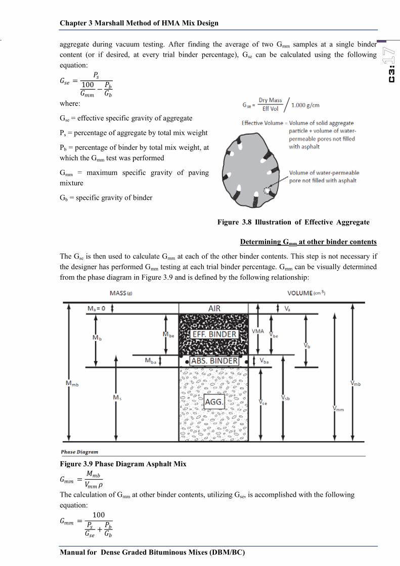
Chapter 3 Marshall Method of HMA Mix Design
Manual for Dense Graded Bituminous Mixes (DBM/BC)
C3:
aggregate during vacuum testing. After finding the average of two Gmm samples at a single binder content (or if desired, at every trial binder percentage), Gse can be calculated using the following equation:
𝐺𝐺𝑠𝑠𝑒𝑒𝑃𝑃𝑠𝑠
𝐺𝐺𝑚𝑚𝑚𝑚 − 𝑃𝑃𝑏𝑏𝐺𝐺𝑏𝑏
where:
Gse = effective specific gravity of aggregate
Ps = percentage of aggregate by total mix weight
Pb = percentage of binder by total mix weight, at which the Gmm test was performed
Gmm = maximum specific gravity of paving mixture
Gb = specific gravity of binder
Determining Gmm at other binder contents
The Gse is then used to calculate Gmm at each of the other binder contents. This step is not necessary if the designer has performed Gmm testing at each trial binder percentage. Gmm can be visually determined from the phase diagram in Figure 3.9 and is defined by the following relationship:
Figure 3.9 Phase Diagram Asphalt Mix
𝐺𝐺𝑚𝑚𝑚𝑚𝑀𝑀𝑚𝑚𝑏𝑏𝑉𝑉𝑚𝑚𝑚𝑚 𝜌𝜌
The calculation of Gmm at other binder contents, utilizing Gse, is accomplished with the following equation:
𝐺𝐺𝑚𝑚𝑚𝑚 𝑃𝑃𝑠𝑠𝐺𝐺𝑠𝑠𝑒𝑒
𝑃𝑃𝑏𝑏𝐺𝐺𝑏𝑏
Figure 3.8 Illustration of Effective Aggregate
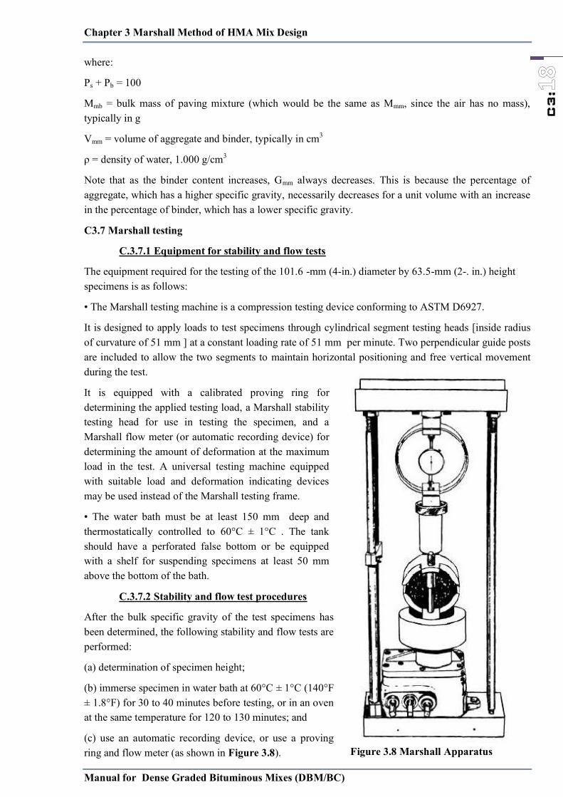
Chapter 3 Marshall Method of HMA Mix Design
Manual for Dense Graded Bituminous Mixes (DBM/BC)
C3:
where:
Ps + Pb = 100
Mmb = bulk mass of paving mixture (which would be the same as Mmm, since the air has no mass), typically in g
Vmm = volume of aggregate and binder, typically in cm3
ρ = density of water, 1.000 g/cm3
Note that as the binder content increases, Gmm always decreases. This is because the percentage of aggregate, which has a higher specific gravity, necessarily decreases for a unit volume with an increase in the percentage of binder, which has a lower specific gravity.
C3.7 Marshall testing
C.3.7.1 Equipment for stability and flow tests
The equipment required for the testing of the 101.6 -mm (4-in.) diameter by 63.5-mm (2-. in.) height specimens is as follows:
• The Marshall testing machine is a compression testing device conforming to ASTM D6927.
It is designed to apply loads to test specimens through cylindrical segment testing heads [inside radius of curvature of 51 mm ] at a constant loading rate of 51 mm per minute. Two perpendicular guide posts are included to allow the two segments to maintain horizontal positioning and free vertical movement during the test.
It is equipped with a calibrated proving ring for determining the applied testing load, a Marshall stability testing head for use in testing the specimen, and a Marshall flow meter (or automatic recording device) for determining the amount of deformation at the maximum load in the test. A universal testing machine equipped with suitable load and deformation indicating devices may be used instead of the Marshall testing frame.
• The water bath must be at least 150 mm deep and thermostatically controlled to 60°C ± 1°C . The tank should have a perforated false bottom or be equipped with a shelf for suspending specimens at least 50 mm above the bottom of the bath.
C.3.7.2 Stability and flow test procedures
After the bulk specific gravity of the test specimens has been determined, the following stability and flow tests are performed:
(a) determination of specimen height;
(b) immerse specimen in water bath at 60°C ± 1°C (140°F ± 1.8°F) for 30 to 40 minutes before testing, or in an oven at the same temperature for 120 to 130 minutes; and
(c) use an automatic recording device, or use a proving ring and flow meter (as shown in Figure 3.8).
Figure 3.8 Marshall Apparatus
Chapter 3 Marshall Method of HMA Mix Design
Manual for Dense Graded Bituminous Mixes (DBM/BC)
C3:
Place the flow meter over the marked guide rod and ―zero‖ the flow meter while holding it firmly against the upper segment of the testing head while the load is being applied.
The same assembly of the testing head and flow meter must be used in testing all specimens. Specimens should be 101.6 ± 0.25 mm (4.00 ± 0.01 in.). Otherwise, an initial and final reading of the flow meter is required for the determination of the flow value.
(d) Thoroughly clean the inside surfaces of the testing heads. Temperature of heads should be maintained between 21.1 and 37.8°C using a water bath, when required.
Lubricate guide rods with a thin film of oil so that the upper test head will slide freely without binding. If a proving ring is used to measure applied load, check to see that the dial indicator is firmly fixed and ―zeroed‖ for the ―no-load‖ position.
(e) With the testing apparatus ready, remove the test specimen from water bath and carefully dry surface with a towel. Place specimen in lower testing head and center; then fit upper testing head into position and center complete assembly in loading device. Place flow meter over marked guide rod as noted in (c) above.
(f) Apply testing load to specimen at a constant rate of deformation, 51 mm per minute, until failure occurs. The point of failure is defined when the maximum load reading is obtained. The total force in Newtons (N) required to produce failure of the specimen should be recorded as its Marshall stability value.
(g) While the stability test is in progress (if not using an automatic recording device), hold the flow meter firmly in position over the guide rod and remove immediately when the load begins to decrease, take reading and record.
This reading is the flow value for the specimen, expressed in units of 0.25 mm. For example, if the specimen deformed 3.8 mm, the flow value is 15.
(h) The entire procedure for both the stability and flow measurements, starting with the removal of the specimen from the water bath, should be completed within a period of 30 seconds.
(i) The Marshall stability is corrected for specimens with a height different than 63.5 mm ( Table 3.6).
Table 3.6 Stability Correlation Ratios Volume of Specimen,
cm3 Approximate Thickness of
Specimen, mm Correlation Ratio 200 to 213 25.4 5.56 214 to 225 27 5 226 to 237 28.6 4.55 238 to 250 30.2 4.17 251 to 264 31.8 3.85 265 to 276 33.3 3.57 277 to 289 34.9 3.33 290 to 301 36.5 3.03 302 to 316 38.1 2.78 317 to 328 39.7 2.5 329 to 340 41.3 2.27 341 to 353 42.9 2.08 354 to 367 44.4 1.92 368 to 379 46 1.79 380 to 392 47.6 1.67

Chapter 3 Marshall Method of HMA Mix Design
Manual for Dense Graded Bituminous Mixes (DBM/BC)
C3:
Volume of Specimen, cm3
Approximate Thickness of Specimen, mm Correlation Ratio
393 to 405 49.2 1.56 406 to 420 50.8 1.47 421 to 431 52.4 1.39 432 to 443 54 1.32 444 to 456 55.6 1.25 457 to 470 57.2 1.19 471 to 482 58.7 1.14 483 to 495 60.3 1.09 496 to 508 61.9 1.04 509 to 522 63.5 1 523 to 535 65.1 0.96 536 to 546 66.7 0.93 547 to 559 68.3 0.89 560 to 573 69.8 0.86 574 to 585 71.4 0.83 586 to 598 73 0.81 599 to 610 74.6 0.78 611 to 625 76.2 0.76
Notes:
1. The measured stability of a specimen multiplied by the ratio for the thickness of the specimen equals the corrected stability for a 63.5-mm specimen.
2. Volume-thickness relationship is based on a specimen diameter of 101.6 mm.
C.3.7.3 Marshall stability and flow considerations
Marshall stability is the peak resistance load obtained during a constant rate of deformation. Marshall flow is a measure of the deformation (elastic plus plastic) of the specimen determined during the stability test. The determination of the Marshall flow with an automatic recording device will typically produce a plot comparable to the stylized Figure 3.9.
Figure 3.9 Determining Marshall Flow
The bottom portion of the Marshall stability versus Marshall flow curve shows the effects of irregularities on the specimen surface until full contact (seating) of the testing heads and the specimen surface is achieved. Therefore, when using an automatic recording device, the recorded Marshall flow
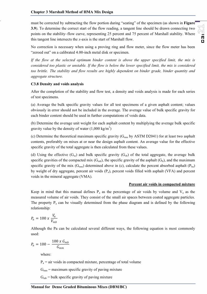
Chapter 3 Marshall Method of HMA Mix Design
Manual for Dense Graded Bituminous Mixes (DBM/BC)
C3:
must be corrected by subtracting the flow portion during ―seating‖ of the specimen (as shown in Figure 3.9). To determine the correct start of the flow reading, a tangent line should be drawn connecting two points on the stability–flow curve, representing 25 percent and 75 percent of Marshall stability. Where this tangent line intersects the x-axis is the start of Marshall flow.
No correction is necessary when using a proving ring and flow meter, since the flow meter has been ―zeroed out‖ on a calibrated 4.00-inch metal disk or specimen.
If the flow at the selected optimum binder content is above the upper specified limit, the mix is considered too plastic or unstable. If the flow is below the lower specified limit, the mix is considered too brittle. The stability and flow results are highly dependent on binder grade, binder quantity and aggregate structure.
C3.8 Density and voids analysis
After the completion of the stability and flow test, a density and voids analysis is made for each series of test specimens.
(a) Average the bulk specific gravity values for all test specimens of a given asphalt content; values obviously in error should not be included in the average. The average value of bulk specific gravity for each binder content should be used in further computations of voids data.
(b) Determine the average unit weight for each asphalt content by multiplying the average bulk specific gravity value by the density of water (1,000 kg/m3)
(c) Determine the theoretical maximum specific gravity (Gmm by ASTM D2041) for at least two asphalt contents, preferably on mixes at or near the design asphalt content. An average value for the effective specific gravity of the total aggregate is then calculated from these values.
(d) Using the effective (Gse) and bulk specific gravity (Gsb) of the total aggregate, the average bulk specific gravities of the compacted mix (Gmb), the specific gravity of the asphalt (Gb), and the maximum specific gravity of the mix (Gmm) determined above in (c), calculate the percent absorbed asphalt (Pba) by weight of dry aggregate, percent air voids (Pa), percent voids filled with asphalt (VFA) and percent voids in the mineral aggregate (VMA).
Percent air voids in compacted mixture
Keep in mind that this manual defines Pa as the percentage of air voids by volume and Va as the measured volume of air voids. They consist of the small air spaces between coated aggregate particles. The property Pa can be visually determined from the phase diagram and is defined by the following relationship:
𝑃𝑃𝑎𝑎 𝑥𝑥 𝑉𝑉𝑎𝑎𝑉𝑉𝑚𝑚𝑏𝑏
Although the Pa can be calculated several different ways, the following equation is most commonly used:
𝑃𝑃𝑎𝑎 − 𝑥𝑥 𝐺𝐺𝑚𝑚𝑏𝑏𝐺𝐺𝑚𝑚𝑚𝑚
where:
Pa = air voids in compacted mixture, percentage of total volume
Gmm = maximum specific gravity of paving mixture
Gmb = bulk specific gravity of paving mixture
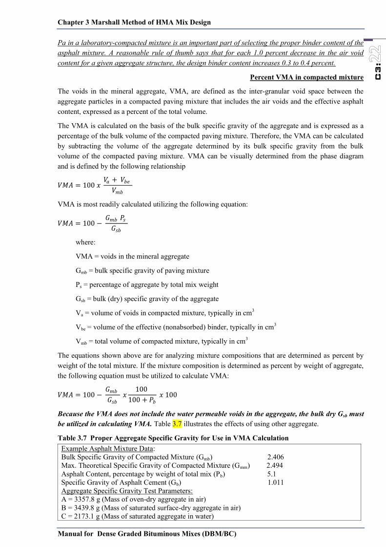
Chapter 3 Marshall Method of HMA Mix Design
Manual for Dense Graded Bituminous Mixes (DBM/BC)
C3:
Pa in a laboratory-compacted mixture is an important part of selecting the proper binder content of the asphalt mixture. A reasonable rule of thumb says that for each 1.0 percent decrease in the air void content for a given aggregate structure, the design binder content increases 0.3 to 0.4 percent.
Percent VMA in compacted mixture
The voids in the mineral aggregate, VMA, are defined as the inter-granular void space between the aggregate particles in a compacted paving mixture that includes the air voids and the effective asphalt content, expressed as a percent of the total volume.
The VMA is calculated on the basis of the bulk specific gravity of the aggregate and is expressed as a percentage of the bulk volume of the compacted paving mixture. Therefore, the VMA can be calculated by subtracting the volume of the aggregate determined by its bulk specific gravity from the bulk volume of the compacted paving mixture. VMA can be visually determined from the phase diagram and is defined by the following relationship
𝑉𝑉𝑀𝑀𝐴𝐴 𝑥𝑥 𝑉𝑉𝑎𝑎 𝑉𝑉𝑏𝑏𝑒𝑒𝑉𝑉𝑚𝑚𝑏𝑏
VMA is most readily calculated utilizing the following equation:
𝑉𝑉𝑀𝑀𝐴𝐴 − 𝐺𝐺𝑚𝑚𝑏𝑏 𝑃𝑃𝑠𝑠𝐺𝐺𝑠𝑠𝑏𝑏
where:
VMA = voids in the mineral aggregate
Gmb = bulk specific gravity of paving mixture
Ps = percentage of aggregate by total mix weight
Gsb = bulk (dry) specific gravity of the aggregate
Va = volume of voids in compacted mixture, typically in cm3
Vbe = volume of the effective (nonabsorbed) binder, typically in cm3
Vmb = total volume of compacted mixture, typically in cm3
The equations shown above are for analyzing mixture compositions that are determined as percent by weight of the total mixture. If the mixture composition is determined as percent by weight of aggregate, the following equation must be utilized to calculate VMA:
𝑉𝑉𝑀𝑀𝐴𝐴 − 𝐺𝐺𝑚𝑚𝑏𝑏𝐺𝐺𝑠𝑠𝑏𝑏
𝑥𝑥 𝑃𝑃𝑏𝑏𝑥𝑥
Because the VMA does not include the water permeable voids in the aggregate, the bulk dry Gsb must be utilized in calculating VMA. Table 3.7 illustrates the effects of using other aggregate.
Table 3.7 Proper Aggregate Specific Gravity for Use in VMA Calculation Example Asphalt Mixture Data: Bulk Specific Gravity of Compacted Mixture (Gmb) 2.406 Max. Theoretical Specific Gravity of Compacted Mixture (Gmm) 2.494 Asphalt Content, percentage by weight of total mix (Pb) 5.1 Specific Gravity of Asphalt Cement (Gb) 1.011 Aggregate Specific Gravity Test Parameters: A = 3357.8 g (Mass of oven-dry aggregate in air) B = 3439.8 g (Mass of saturated surface-dry aggregate in air) C = 2173.1 g (Mass of saturated aggregate in water)
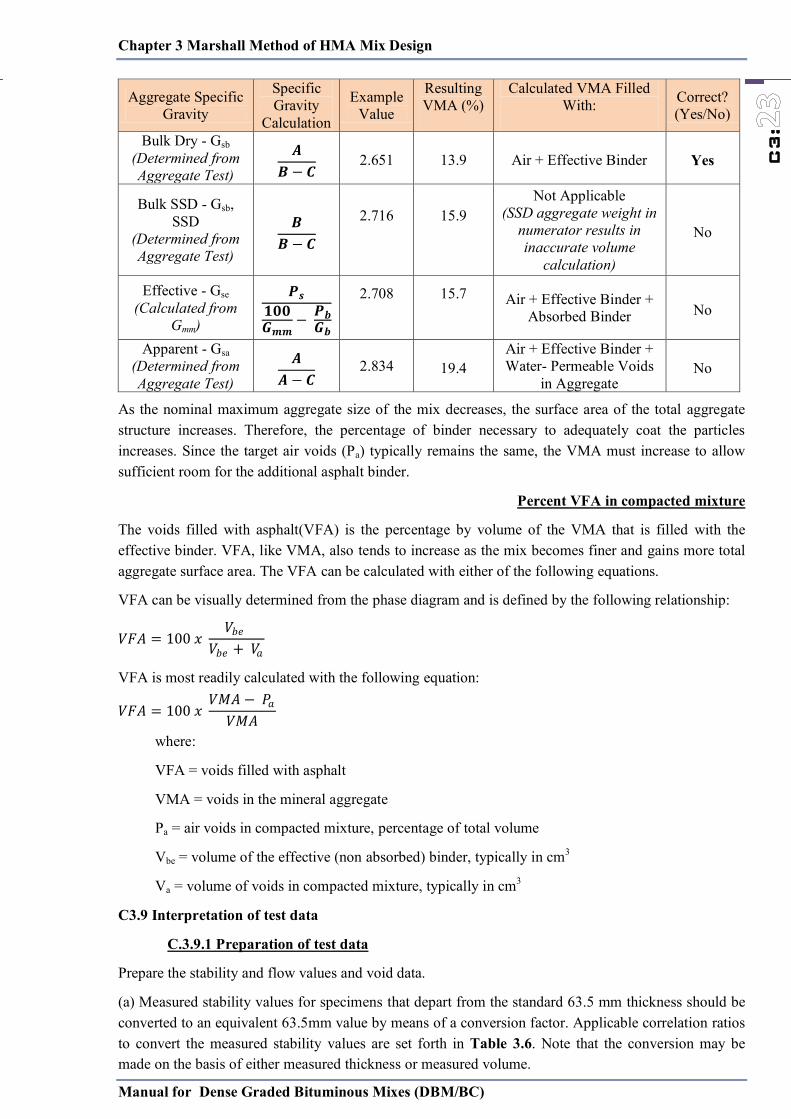
Chapter 3 Marshall Method of HMA Mix Design
Manual for Dense Graded Bituminous Mixes (DBM/BC)
C3:
Aggregate Specific Gravity
Specific Gravity
Calculation
Example Value
Resulting VMA (%)
Calculated VMA Filled With:
Correct? (Yes/No)
Bulk Dry - Gsb (Determined from Aggregate Test)
𝑨𝑨𝑩𝑩 − 𝑪𝑪 2.651 13.9 Air + Effective Binder Yes
Bulk SSD - Gsb, SSD
(Determined from Aggregate Test)
𝑩𝑩𝑩𝑩 − 𝑪𝑪
2.716
15.9
Not Applicable (SSD aggregate weight in
numerator results in inaccurate volume
calculation)
No
Effective - Gse (Calculated from
Gmm)
𝑷𝑷𝒔𝒔𝟏𝟏𝟎𝟎𝟎𝟎𝑮𝑮𝒎𝒎𝒎𝒎 − 𝑷𝑷𝒃𝒃
𝑮𝑮𝒃𝒃 2.708
15.7
Air + Effective Binder +
Absorbed Binder No
Apparent - Gsa (Determined from Aggregate Test)
𝑨𝑨𝑨𝑨 − 𝑪𝑪 2.834 19.4
Air + Effective Binder + Water- Permeable Voids
in Aggregate No
As the nominal maximum aggregate size of the mix decreases, the surface area of the total aggregate structure increases. Therefore, the percentage of binder necessary to adequately coat the particles increases. Since the target air voids (Pa) typically remains the same, the VMA must increase to allow sufficient room for the additional asphalt binder.
Percent VFA in compacted mixture
The voids filled with asphalt(VFA) is the percentage by volume of the VMA that is filled with the effective binder. VFA, like VMA, also tends to increase as the mix becomes finer and gains more total aggregate surface area. The VFA can be calculated with either of the following equations.
VFA can be visually determined from the phase diagram and is defined by the following relationship:
𝑉𝑉𝐹𝐹𝐴𝐴 𝑥𝑥 𝑉𝑉𝑏𝑏𝑒𝑒𝑉𝑉𝑏𝑏𝑒𝑒 𝑉𝑉𝑎𝑎
VFA is most readily calculated with the following equation:
𝑉𝑉𝐹𝐹𝐴𝐴 𝑥𝑥 𝑉𝑉𝑀𝑀𝐴𝐴 − 𝑃𝑃𝑎𝑎𝑉𝑉𝑀𝑀𝐴𝐴
where:
VFA = voids filled with asphalt
VMA = voids in the mineral aggregate
Pa = air voids in compacted mixture, percentage of total volume
Vbe = volume of the effective (non absorbed) binder, typically in cm3
Va = volume of voids in compacted mixture, typically in cm3
C3.9 Interpretation of test data
C.3.9.1 Preparation of test data
Prepare the stability and flow values and void data.
(a) Measured stability values for specimens that depart from the standard 63.5 mm thickness should be converted to an equivalent 63.5mm value by means of a conversion factor. Applicable correlation ratios to convert the measured stability values are set forth in Table 3.6. Note that the conversion may be made on the basis of either measured thickness or measured volume.

Chapter 3 Marshall Method of HMA Mix Design
Manual for Dense Graded Bituminous Mixes (DBM/BC)
C3:
(b) Average the flow values and the final converted stability values for all specimens of given asphalt content. Values that are obviously in error should not be included in the average.
(c) Prepare separate graphical plots for the following values and connect plotted points with a smooth curve that obtains the ―best fit‖ for all values, as illustrated in Figure 3.10
• percent air voids (Pa) versus asphalt content;
• percent voids in mineral aggregate (VMA) versus asphalt content;
• percent voids filled with asphalt (VFA) versus asphalt content;
• unit weight of total mix versus asphalt content;
• stability versus asphalt content; and
• flow versus asphalt content.
Figure 3.10 Test Property Curves for Hot Mix Design Data by the Marshall Method
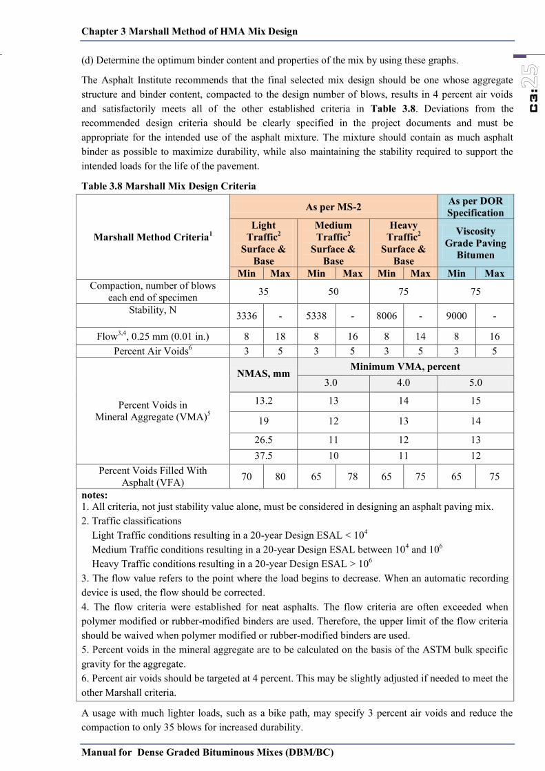
Chapter 3 Marshall Method of HMA Mix Design
Manual for Dense Graded Bituminous Mixes (DBM/BC)
C3:
(d) Determine the optimum binder content and properties of the mix by using these graphs.
The Asphalt Institute recommends that the final selected mix design should be one whose aggregate structure and binder content, compacted to the design number of blows, results in 4 percent air voids and satisfactorily meets all of the other established criteria in Table 3.8. Deviations from the recommended design criteria should be clearly specified in the project documents and must be appropriate for the intended use of the asphalt mixture. The mixture should contain as much asphalt binder as possible to maximize durability, while also maintaining the stability required to support the intended loads for the life of the pavement.
Table 3.8 Marshall Mix Design Criteria
Marshall Method Criteria1
As per MS-2 As per DOR Specification
Light Traffic2
Surface & Base
Medium Traffic2
Surface & Base
Heavy Traffic2
Surface & Base
Viscosity Grade Paving
Bitumen
Min Max Min Max Min Max Min Max Compaction, number of blows
each end of specimen 35 50 75 75
Stability, N 3336 - 5338 - 8006 - 9000 -
Flow3,4, 0.25 mm (0.01 in.) 8 18 8 16 8 14 8 16 Percent Air Voids6 3 5 3 5 3 5 3 5
Percent Voids in Mineral Aggregate (VMA)5
NMAS, mm Minimum VMA, percent
3.0 4.0 5.0
13.2 13 14 15
19 12 13 14
26.5 11 12 13 37.5 10 11 12
Percent Voids Filled With Asphalt (VFA) 70 80 65 78 65 75 65 75
notes: 1. All criteria, not just stability value alone, must be considered in designing an asphalt paving mix. 2. Traffic classifications Light Traffic conditions resulting in a 20-year Design ESAL < 104 Medium Traffic conditions resulting in a 20-year Design ESAL between 104 and 106 Heavy Traffic conditions resulting in a 20-year Design ESAL > 106 3. The flow value refers to the point where the load begins to decrease. When an automatic recording device is used, the flow should be corrected. 4. The flow criteria were established for neat asphalts. The flow criteria are often exceeded when polymer modified or rubber-modified binders are used. Therefore, the upper limit of the flow criteria should be waived when polymer modified or rubber-modified binders are used. 5. Percent voids in the mineral aggregate are to be calculated on the basis of the ASTM bulk specific gravity for the aggregate. 6. Percent air voids should be targeted at 4 percent. This may be slightly adjusted if needed to meet the other Marshall criteria.
A usage with much lighter loads, such as a bike path, may specify 3 percent air voids and reduce the compaction to only 35 blows for increased durability.

Chapter 3 Marshall Method of HMA Mix Design
Manual for Dense Graded Bituminous Mixes (DBM/BC)
C3:
C.3.9.2 Trends and relations of test data
By examining the test property curves plotted on Figure 3.10, information can be learned about the sensitivity of the mixture to asphalt content. The test property curves have been found to follow a reasonably consistent pattern for dense-graded asphalt paving mixes, but variations do and will occur. Trends generally noted are:
• The stability value increases with increasing asphalt content up to a maximum, after which the stability decreases.
• The flow value consistently increases with increasing asphalt content.
• The curve for unit weight of total mix follows the trend similar to the stability curve, except that the maximum unit weight normally (but not always) occurs at slightly higher asphalt content than the maximum stability.
• The percent of air voids, Pa, steadily decreases with increasing asphalt content, ultimately approaching a minimum void content.
• The percent voids in the mineral aggregate, VMA, generally decreases (because of better compaction) to a minimum value, and then increases with increasing asphalt content, because the aggregate is starting to be pushed apart by excessive binder in the mix.
• The percent voids filled with asphalt, VFA, steadily increases with increasing asphalt content because the VMA is being filled with asphalt.
C3.10 Selection of Design Binder Content (OBC)
The Asphalt Institute recommends that the final selected mix design should be one whose aggregate structure and binder content, compacted to the design number of blows, results in 4 percent air voids and satisfactorily meets all of the other established criteria in Table 3.8. Deviations from the recommended design criteria should be clearly specified in the project documents and must be appropriate for the intended use of the asphalt mixture. The mixture should contain as much asphalt binder as possible to maximize durability, while also maintaining the stability required to support the intended loads for the life of the pavement.
Table 3.9 Minimum Bitumen Content Composition for BC DBM
NMAS 19 mm 13.2 mm 26.5 mm 35.5 mm Bitumen content % by mass of total
mix Min 5.2 Min 5.4 Min 4.5 Min 4.0
Corresponds to specific gravity of aggregates being 2.7. In case aggregate have specific gravity more than 2. 7, the minimum bitumen content can be reduced proportionately. Further the region where highest daily mean air temperature is 30°C or lower and lowest daily air temperature is - 10°C or lower, the bitumen content may be increased by 0.5 percent.
C3.10 Modified Marshall method for large aggregate
The procedure is basically the same as the original Marshall mix design method except for these differences that are due to the larger specimen size:
• The hammer weighs 10.2 kg and has a 149.4-mm flat tamping face. Only a mechanically operated device is used for the same 457-mm drop height.
• The specimen has a 152.4-mm diameter by 95.2-mm height.
Chapter 3 Marshall Method of HMA Mix Design
Manual for Dense Graded Bituminous Mixes (DBM/BC)
C3:
• The batch weights are typically 4,050 g.
• The equipment for compacting and testing (molds and breaking heads) are proportionately larger to accommodate the larger specimens.
• The mix is placed in the mold in two approximately equal increments, with spading performed after each increment.
• The number of blows needed for the larger specimen is 1.5 times (75 or 112 blows) of that required for the smaller specimen (50 or 75 blows) to obtain equivalent compaction.
• The design criteria should be modified as well. The minimum stability should be 2.25 times, and the range of flow values should be 1.5 times the criteria listed in Table 3.8.
• The correction values as listed in Table 3.10 should be used to convert the measured stability values to an equivalent value for a specimen with a 95.2 thickness.
Table 3.10 Stability Corrections for Large Stone Marshall Mixes in 6" Molds
Approximate Height, mm Specimen Volume,(cc) Correlation Ratio
88.9 1608 to 1626 1.12
90.5 1637 to 1665 1.09
92.1 1666 to 1694 1.06
93.7 1695 to 1723 1.03
95.2 1724 to 1752 1.00
96.8 1753 to 1781 0.97
98.4 1782 to 1810 0.95
100 1811 to 1839 0.92
101.6 1840 to 1868 0.9

Cha
pter
3 M
arsh
all M
etho
d of
HM
A M
ix D
esig
n M
anua
l for
Den
se G
rade
d B
itum
inou
s Mix
es (D
BM
/BC
)
C3:
Tes
t Rep
ort S
how
ing
Typi
cal L
ab D
ata
for
Des
ign
by th
e M
arsh
all M
etho
d
Nam
e of
Pro
ject
:
Loc
atio
n:
Dat
e:
Prop
ortio
n o
f Agg
rega
te fr
actio
ns :
38.
0-25
.0 m
m :
:
2
5.0
to 1
9.0
mm
::
1
9.0
to 1
3.2
mm
::
13.2
to 4
.75
mm
::
4.75
to 2
.36
mm
::
Pa
ssin
g 2.
36 m
m :
Com
pact
ion
:
Bitu
men
Visc
osity
Gra
de:
S
p.G
ravi
ty o
f Bitu
men
(Gb)
:
Sp.
Gra
vity
of A
ggre
gate
ble
nd (G
sb)
The
oret
ical
max
. Sp.
Gra
vity
of
mix
(Gm
m) :
Eff
ectiv
e Sp
. Gra
vity
of A
ggre
gate
(Gse
):
Abs
orbe
d B
itum
en (P
ba) :
Sp
ecim
en D
iam
eter
(in
mm
) :
SN
Bitu
men
, %
(Pb)
Fille
r/ D
ust %
A
ggre
gate
M
ix, %
(Ps)
Spec
ifica
tion
Mas
s, gm
B
ulk
Vol
ume,
cm
3
Bul
k S.
G. o
f Sp
ecim
en
(Gm
b)
% A
ir V
oid
(Pa)
%
VM
A
%
VFA
St
abili
ty,N
Fl
ow
In a
ir In
w
ater
SS
D in
ai
r M
easu
red
Cor
rect
ed
Pb+
P s =
100
%
𝐺𝐺 𝑚𝑚𝑚𝑚
𝑃𝑃 𝑠𝑠 𝐺𝐺 𝑠𝑠𝑒𝑒
𝑃𝑃 𝑏𝑏 𝐺𝐺 𝑏𝑏
𝐺𝐺 𝑠𝑠𝑏𝑏
𝑃𝑃𝑃𝑃
…𝑃𝑃 𝑛𝑛
𝑃𝑃 𝐺𝐺𝑃𝑃 𝐺𝐺
…𝑃𝑃 𝑛𝑛 𝐺𝐺 𝑛𝑛
𝑃𝑃 𝑎𝑎−
𝑥𝑥𝐺𝐺𝑚𝑚𝑏𝑏
𝐺𝐺 𝑚𝑚𝑚𝑚
𝑉𝑉𝑀𝑀𝐴𝐴
−𝐺𝐺 𝑚𝑚
𝑏𝑏𝑃𝑃 𝑠𝑠
𝐺𝐺 𝑠𝑠𝑏𝑏
𝑉𝑉𝐹𝐹𝐴𝐴
𝑥𝑥𝑉𝑉𝑀𝑀
𝐴𝐴−𝑃𝑃 𝑎𝑎
𝑉𝑉𝑀𝑀𝐴𝐴

Chapter 4 Hot-Mix Asphalt Plant Operations
Manual for Dense Graded Bituminous Mixes (DBM/BC)
C4:
C4.1: General
The purpose of an HMA plant is to blend aggregate and asphalt together at an elevated temperature to produce a homogeneous asphalt paving mixture. There are three basic types of HMA plants in use: batch, parallel-flow drum-mix, and counter-flow drum-mix. All three types serve the same ultimate purpose, and the asphalt mixture should be essentially similar regardless of the type of plant used to manufacture it. The three types of plants differ, however, in operation and flow of materials, as described in the following sections.
C4.2 : Asphalt Plants C4.2.1 Batch Plant
The major components of a batch plant are the cold-feed system, asphalt supply system, aggregate dryer, mixing tower, and emission-control system. A typical batch plant is depicted in Figure 4.1 the major plant components are shown in Figure 4.2. The batch plant tower consists of a hot elevator, a screen deck, hot bins, a weigh hopper, an Bitumen weigh bucket, and a pugmill. The flow of materials in a batch tower is illustrated in Figure 4.3.
Figure 4.1 Typical Batch Plant
The aggregate used in the mix is removed from stockpiles and placed in individual cold-feed bins. Aggregates of different sizes are proportioned out of their bins by a combination of the size of the opening of the gate at the bottom of each bin and the speed of the conveyor belt under the bin. Generally, a feeder belt beneath each bin deposits the aggregate on a gathering conveyor located under all of the cold-feed bins. The aggregate is transported by the gathering conveyor and transferred to a charging conveyor. The material on the charging conveyor is then carried up to the aggregate dryer.
The dryer operates on a counter-flow basis. The aggregate is introduced into the dryer at the upper end and is moved down the drum by both the drum rotation (gravity flow) and the flight configuration inside the rotating dryer. The burner is located at the lower end of the dryer, and the exhaust gases from the combustion and drying process move toward the upper end of the dryer, against (counter to) the flow of the aggregate. As the aggregate is tumbled through the exhaust gases, the material is heated and dried. Moisture is removed and carried out of the dryer as part of the exhaust gas stream. The hot, dry aggregate is then discharged from the dryer at the lower end.
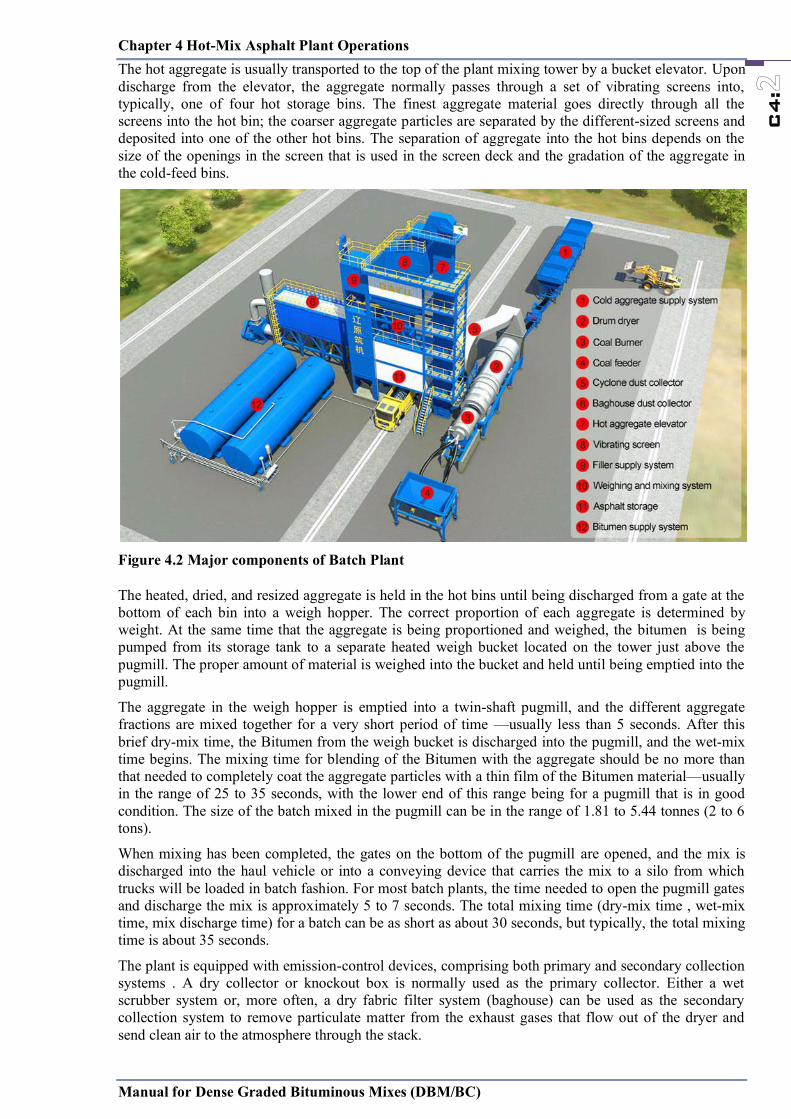
Chapter 4 Hot-Mix Asphalt Plant Operations
Manual for Dense Graded Bituminous Mixes (DBM/BC)
C4:
The hot aggregate is usually transported to the top of the plant mixing tower by a bucket elevator. Upon discharge from the elevator, the aggregate normally passes through a set of vibrating screens into, typically, one of four hot storage bins. The finest aggregate material goes directly through all the screens into the hot bin; the coarser aggregate particles are separated by the different-sized screens and deposited into one of the other hot bins. The separation of aggregate into the hot bins depends on the size of the openings in the screen that is used in the screen deck and the gradation of the aggregate in the cold-feed bins.
Figure 4.2 Major components of Batch Plant
The heated, dried, and resized aggregate is held in the hot bins until being discharged from a gate at the bottom of each bin into a weigh hopper. The correct proportion of each aggregate is determined by weight. At the same time that the aggregate is being proportioned and weighed, the bitumen is being pumped from its storage tank to a separate heated weigh bucket located on the tower just above the pugmill. The proper amount of material is weighed into the bucket and held until being emptied into the pugmill.
The aggregate in the weigh hopper is emptied into a twin-shaft pugmill, and the different aggregate fractions are mixed together for a very short period of time —usually less than 5 seconds. After this brief dry-mix time, the Bitumen from the weigh bucket is discharged into the pugmill, and the wet-mix time begins. The mixing time for blending of the Bitumen with the aggregate should be no more than that needed to completely coat the aggregate particles with a thin film of the Bitumen material—usually in the range of 25 to 35 seconds, with the lower end of this range being for a pugmill that is in good condition. The size of the batch mixed in the pugmill can be in the range of 1.81 to 5.44 tonnes (2 to 6 tons).
When mixing has been completed, the gates on the bottom of the pugmill are opened, and the mix is discharged into the haul vehicle or into a conveying device that carries the mix to a silo from which trucks will be loaded in batch fashion. For most batch plants, the time needed to open the pugmill gates and discharge the mix is approximately 5 to 7 seconds. The total mixing time (dry-mix time , wet-mix time, mix discharge time) for a batch can be as short as about 30 seconds, but typically, the total mixing time is about 35 seconds.
The plant is equipped with emission-control devices, comprising both primary and secondary collection systems . A dry collector or knockout box is normally used as the primary collector. Either a wet scrubber system or, more often, a dry fabric filter system (baghouse) can be used as the secondary collection system to remove particulate matter from the exhaust gases that flow out of the dryer and send clean air to the atmosphere through the stack.
Chapter 4 Hot-Mix Asphalt Plant Operations
Manual for Dense Graded Bituminous Mixes (DBM/BC)
C4:
Figure 4.3 Flow of materials in a batch tower
C4.2.2. Parallel-Flow Drum-Mix Plants
The parallel-flow drum-mix plant is a variation of the old-style continuous-mix plant. It consists of five major components: the cold-feed system, Bitumen supply system, drum mixer, surge or storage silos, and emission-control equipment. A typical parallel-flow drum-mix plant is depicted in Figure 4.4; the major plant components are shown in Figure 4.5.
The cold-feed bins are used to proportion the material to the plant. A variable-speed feeder belt is used under each bin. The amount of aggregate drawn from each bin can thus be controlled by both the size of the gate opening and the speed of the feeder belt to provide accurate delivery of the different-sized materials. The aggregate on each feeder belt is deposited onto a gathering conveyor that runs beneath all of the cold-feed bins. The combined material is normally passed through a scalping screen and then transferred to a charging conveyor for transport to the drum mixer.
The charging conveyor is equipped with two devices that are used to determine the amount of aggregate being delivered to the plant: a weigh bridge under the conveyor belt measures the weight of the aggregate passing over it, and a sensor determines the speed of the belt. These two values are used to compute the wet weight of aggregate, in tonnes (tons) per hour, entering the drum mixer. The plant computer, with the amount of moisture in the aggregate provided as an input value, converts the wet weight to dry weight in order to determine the correct amount of Bitumen needed in the mix.
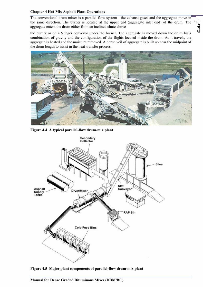
Chapter 4 Hot-Mix Asphalt Plant Operations
Manual for Dense Graded Bituminous Mixes (DBM/BC)
C4:
The conventional drum mixer is a parallel-flow system—the exhaust gases and the aggregate move in the same direction. The burner is located at the upper end (aggregate inlet end) of the drum. The aggregate enters the drum either from an inclined chute above
the burner or on a Slinger conveyor under the burner. The aggregate is moved down the drum by a combination of gravity and the configuration of the flights located inside the drum. As it travels, the aggregate is heated and the moisture removed. A dense veil of aggregate is built up near the midpoint of the drum length to assist in the heat-transfer process.
Figure 4.4 A typical parallel-flow drum-mix plant
Figure 4.5 Major plant components of parallel-flow drum-mix plant
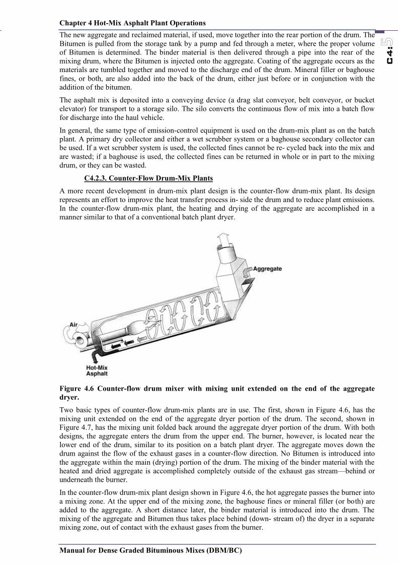
Chapter 4 Hot-Mix Asphalt Plant Operations
Manual for Dense Graded Bituminous Mixes (DBM/BC)
C4:
The new aggregate and reclaimed material, if used, move together into the rear portion of the drum. The Bitumen is pulled from the storage tank by a pump and fed through a meter, where the proper volume of Bitumen is determined. The binder material is then delivered through a pipe into the rear of the mixing drum, where the Bitumen is injected onto the aggregate. Coating of the aggregate occurs as the materials are tumbled together and moved to the discharge end of the drum. Mineral filler or baghouse fines, or both, are also added into the back of the drum, either just before or in conjunction with the addition of the bitumen.
The asphalt mix is deposited into a conveying device (a drag slat conveyor, belt conveyor, or bucket elevator) for transport to a storage silo. The silo converts the continuous flow of mix into a batch flow for discharge into the haul vehicle.
In general, the same type of emission-control equipment is used on the drum-mix plant as on the batch plant. A primary dry collector and either a wet scrubber system or a baghouse secondary collector can be used. If a wet scrubber system is used, the collected fines cannot be re- cycled back into the mix and are wasted; if a baghouse is used, the collected fines can be returned in whole or in part to the mixing drum, or they can be wasted.
C4.2.3. Counter-Flow Drum-Mix Plants
A more recent development in drum-mix plant design is the counter-flow drum-mix plant. Its design represents an effort to improve the heat transfer process in- side the drum and to reduce plant emissions. In the counter-flow drum-mix plant, the heating and drying of the aggregate are accomplished in a manner similar to that of a conventional batch plant dryer.
Figure 4.6 Counter-flow drum mixer with mixing unit extended on the end of the aggregate dryer.
Two basic types of counter-flow drum-mix plants are in use. The first, shown in Figure 4.6, has the mixing unit extended on the end of the aggregate dryer portion of the drum. The second, shown in Figure 4.7, has the mixing unit folded back around the aggregate dryer portion of the drum. With both designs, the aggregate enters the drum from the upper end. The burner, however, is located near the lower end of the drum, similar to its position on a batch plant dryer. The aggregate moves down the drum against the flow of the exhaust gases in a counter-flow direction. No Bitumen is introduced into the aggregate within the main (drying) portion of the drum. The mixing of the binder material with the heated and dried aggregate is accomplished completely outside of the exhaust gas stream—behind or underneath the burner.
In the counter-flow drum-mix plant design shown in Figure 4.6, the hot aggregate passes the burner into a mixing zone. At the upper end of the mixing zone, the baghouse fines or mineral filler (or both) are added to the aggregate. A short distance later, the binder material is introduced into the drum. The mixing of the aggregate and Bitumen thus takes place behind (down- stream of) the dryer in a separate mixing zone, out of contact with the exhaust gases from the burner.
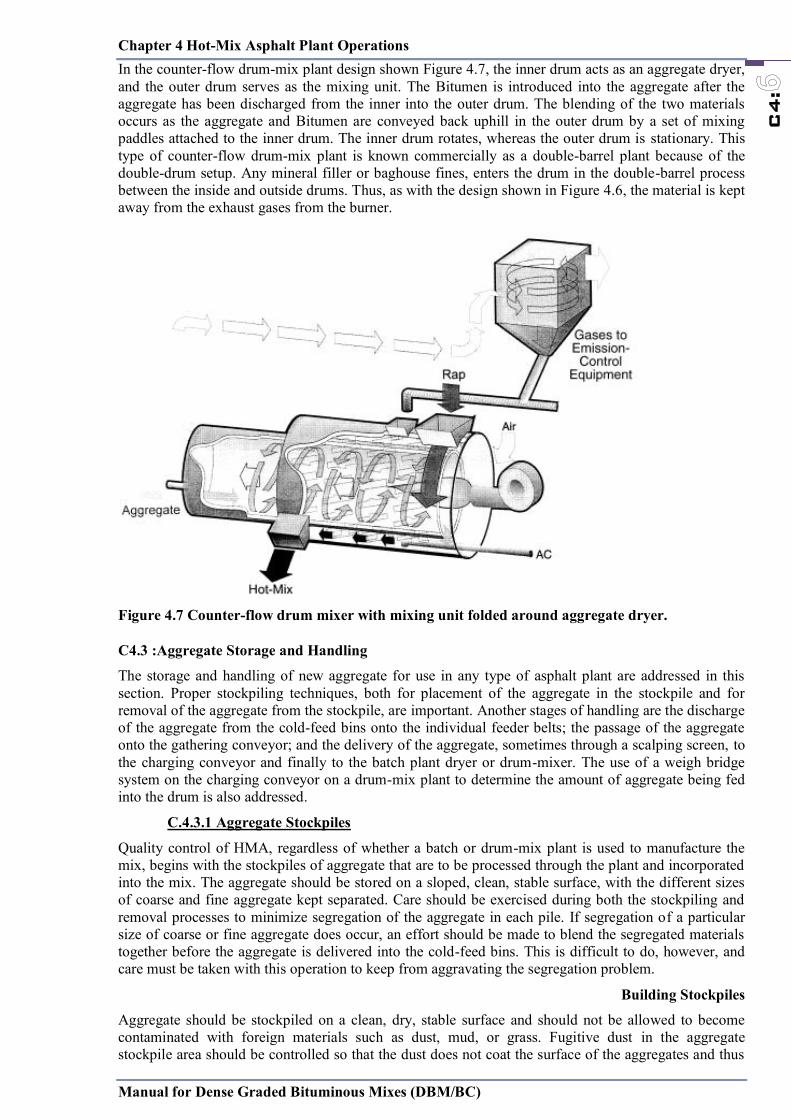
Chapter 4 Hot-Mix Asphalt Plant Operations
Manual for Dense Graded Bituminous Mixes (DBM/BC)
C4:
In the counter-flow drum-mix plant design shown Figure 4.7, the inner drum acts as an aggregate dryer, and the outer drum serves as the mixing unit. The Bitumen is introduced into the aggregate after the aggregate has been discharged from the inner into the outer drum. The blending of the two materials occurs as the aggregate and Bitumen are conveyed back uphill in the outer drum by a set of mixing paddles attached to the inner drum. The inner drum rotates, whereas the outer drum is stationary. This type of counter-flow drum-mix plant is known commercially as a double-barrel plant because of the double-drum setup. Any mineral filler or baghouse fines, enters the drum in the double-barrel process between the inside and outside drums. Thus, as with the design shown in Figure 4.6, the material is kept away from the exhaust gases from the burner.
Figure 4.7 Counter-flow drum mixer with mixing unit folded around aggregate dryer.
C4.3 :Aggregate Storage and Handling
The storage and handling of new aggregate for use in any type of asphalt plant are addressed in this section. Proper stockpiling techniques, both for placement of the aggregate in the stockpile and for removal of the aggregate from the stockpile, are important. Another stages of handling are the discharge of the aggregate from the cold-feed bins onto the individual feeder belts; the passage of the aggregate onto the gathering conveyor; and the delivery of the aggregate, sometimes through a scalping screen, to the charging conveyor and finally to the batch plant dryer or drum-mixer. The use of a weigh bridge system on the charging conveyor on a drum-mix plant to determine the amount of aggregate being fed into the drum is also addressed.
C.4.3.1 Aggregate Stockpiles
Quality control of HMA, regardless of whether a batch or drum-mix plant is used to manufacture the mix, begins with the stockpiles of aggregate that are to be processed through the plant and incorporated into the mix. The aggregate should be stored on a sloped, clean, stable surface, with the different sizes of coarse and fine aggregate kept separated. Care should be exercised during both the stockpiling and removal processes to minimize segregation of the aggregate in each pile. If segregation of a particular size of coarse or fine aggregate does occur, an effort should be made to blend the segregated materials together before the aggregate is delivered into the cold-feed bins. This is difficult to do, however, and care must be taken with this operation to keep from aggravating the segregation problem.
Building Stockpiles
Aggregate should be stockpiled on a clean, dry, stable surface and should not be allowed to become contaminated with foreign materials such as dust, mud, or grass. Fugitive dust in the aggregate stockpile area should be controlled so that the dust does not coat the surface of the aggregates and thus
Chapter 4 Hot-Mix Asphalt Plant Operations
Manual for Dense Graded Bituminous Mixes (DBM/BC)
C4:
does not alter the gradation of the material in each stockpile. The stockpiles should be constructed to be free draining to ensure that the moisture content of the aggregate is as low as possible. Paved stockpile pads should be used to facilitate drainage and provide a solid working platform. Excess moisture, particularly in the fine aggregates (sand), increases the cost of drying the aggregates and reduces the production capacity of the plant. When using a drum-mix plant, the moisture content of each aggregate size should be determined at least twice a day and the average moisture content of the combined aggregates entered into the plant computer system.
Figure 4.8 Covered aggregate stockpiles.
To reduce the amount of moisture that accumulates in the aggregate, especially from rain, it is often cost-effective to cover the aggregate stockpiles. The cover typically is in the form of a roof or a shed, as seen in Figure 4.8. A tarp placed directly on top of the aggregate should generally not be used since moisture will typically collect under the tarp instead of evaporating. If only one roof is used, it should be placed on top of the fine aggregate pile since this material will typically have a higher moisture content than that of the coarser aggregate. If multiple roofs are available, they should then be placed over the various coarse aggregate stockpiles.
As noted, the stockpiles of the various aggregate sizes should be kept separated—by physical barriers, if necessary—at all times. The cold-feed bins and feeders are calibrated to provide a specific amount of each size of aggregate from each bin. If the various materials are blended in the stockpiles, a combination of sizes will occur in each cold-feed bin. This blending of the aggregate will cause variations in the gradation of the HMA produced by a drum-mix plant and may cause problems with unbalanced hot bins in a batch plant.
Segregation is a major concern with stockpiled aggregate. Many aggregate problems are caused by mis-handling of the aggregate during stockpiling and load-out operations. Whenever possible, aggregate should be stockpiled by individual size fractions. A well-graded or continuously graded material should not be contained in one stockpile. Aggregate of larger sizes, particularly when combined with that of smaller sizes, has a tendency to roll down the face of a stockpile and collect at the bottom, leading to segregation.
Prevention of segregation begins with the construction of the stockpile. If possible, stockpiles should be constructed in horizontal or gently sloping layers. If trucks are used to carry the incoming aggregate to the plant site, each load should be dumped in a single pile, as seen in Figure 4.9. Any construction procedure that results in the aggregate being pushed or dumped over the side of the stockpile should be avoided because these practices may result in segregation. Trucks and loaders should be kept off the stockpiles since they can cause aggregate breakage, fines generation, and con- tamination of the stockpile.
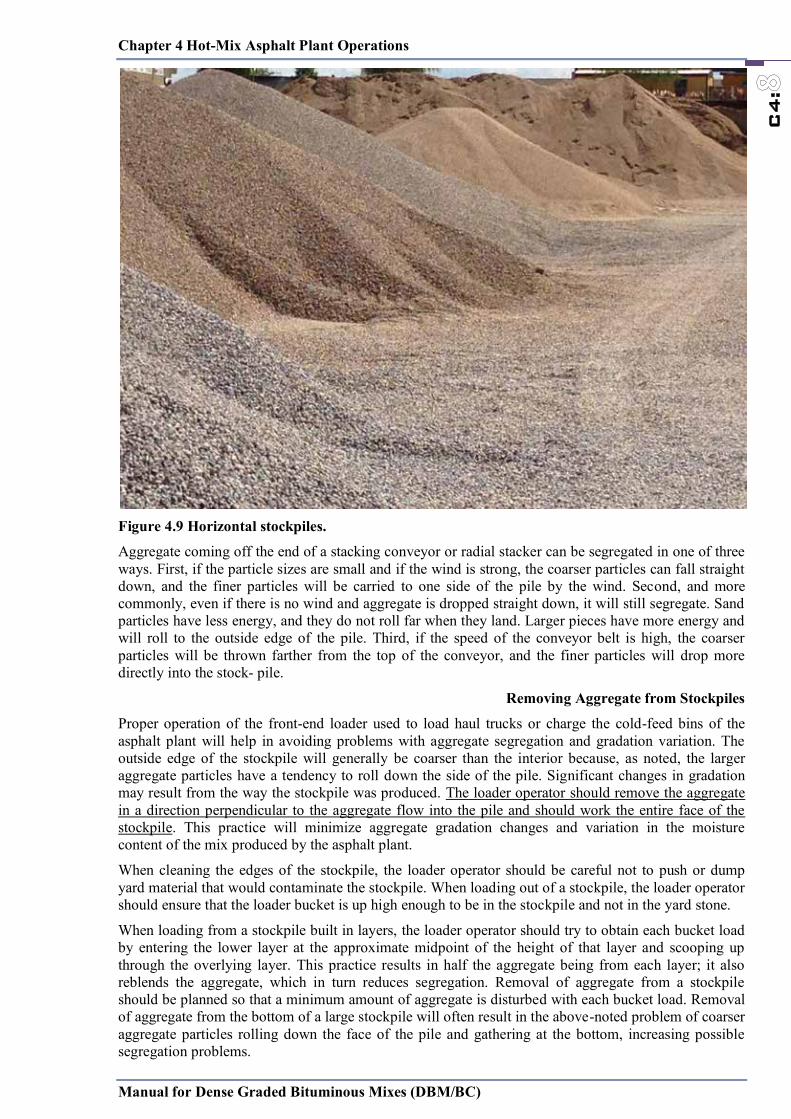
Chapter 4 Hot-Mix Asphalt Plant Operations
Manual for Dense Graded Bituminous Mixes (DBM/BC)
C4:
Figure 4.9 Horizontal stockpiles.
Aggregate coming off the end of a stacking conveyor or radial stacker can be segregated in one of three ways. First, if the particle sizes are small and if the wind is strong, the coarser particles can fall straight down, and the finer particles will be carried to one side of the pile by the wind. Second, and more commonly, even if there is no wind and aggregate is dropped straight down, it will still segregate. Sand particles have less energy, and they do not roll far when they land. Larger pieces have more energy and will roll to the outside edge of the pile. Third, if the speed of the conveyor belt is high, the coarser particles will be thrown farther from the top of the conveyor, and the finer particles will drop more directly into the stock- pile.
Removing Aggregate from Stockpiles
Proper operation of the front-end loader used to load haul trucks or charge the cold-feed bins of the asphalt plant will help in avoiding problems with aggregate segregation and gradation variation. The outside edge of the stockpile will generally be coarser than the interior because, as noted, the larger aggregate particles have a tendency to roll down the side of the pile. Significant changes in gradation may result from the way the stockpile was produced. The loader operator should remove the aggregate in a direction perpendicular to the aggregate flow into the pile and should work the entire face of the stockpile. This practice will minimize aggregate gradation changes and variation in the moisture content of the mix produced by the asphalt plant.
When cleaning the edges of the stockpile, the loader operator should be careful not to push or dump yard material that would contaminate the stockpile. When loading out of a stockpile, the loader operator should ensure that the loader bucket is up high enough to be in the stockpile and not in the yard stone.
When loading from a stockpile built in layers, the loader operator should try to obtain each bucket load by entering the lower layer at the approximate midpoint of the height of that layer and scooping up through the overlying layer. This practice results in half the aggregate being from each layer; it also reblends the aggregate, which in turn reduces segregation. Removal of aggregate from a stockpile should be planned so that a minimum amount of aggregate is disturbed with each bucket load. Removal of aggregate from the bottom of a large stockpile will often result in the above-noted problem of coarser aggregate particles rolling down the face of the pile and gathering at the bottom, increasing possible segregation problems.
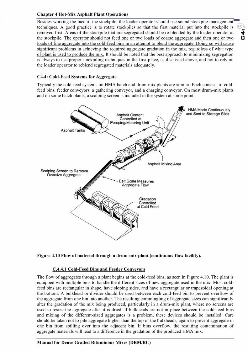
Chapter 4 Hot-Mix Asphalt Plant Operations
Manual for Dense Graded Bituminous Mixes (DBM/BC)
C4:
Besides working the face of the stockpile, the loader operator should use sound stockpile management techniques. A good practice is to rotate stockpiles so that the first material put into the stockpile is removed first. Areas of the stockpile that are segregated should be re-blended by the loader operator at the stockpile. The operator should not feed one or two loads of coarse aggregate and then one or two loads of fine aggregate into the cold-feed bins in an attempt to blend the aggregate. Doing so will cause significant problems in achieving the required aggregate gradation in the mix, regardless of what type of plant is used to produce the mix. It should be noted that the best approach to minimizing segregation is always to use proper stockpiling techniques in the first place, as discussed above, and not to rely on the loader operator to reblend segregated materials adequately.
C4.4: Cold-Feed Systems for Aggregate
Typically the cold-feed systems on HMA batch and drum-mix plants are similar. Each consists of cold-feed bins, feeder conveyors, a gathering conveyor, and a charging conveyor. On most drum-mix plants and on some batch plants, a scalping screen is included in the system at some point.
Figure 4.10 Flow of material through a drum-mix plant (continuous-flow facility).
C.4.4.1 Cold-Feed Bins and Feeder Conveyors
The flow of aggregates through a plant begins at the cold-feed bins, as seen in Figure 4.10. The plant is equipped with multiple bins to handle the different sizes of new aggregate used in the mix. Most cold-feed bins are rectangular in shape, have sloping sides, and have a rectangular or trapezoidal opening at the bottom. A bulkhead or divider should be used between each cold-feed bin to prevent overflow of the aggregate from one bin into another. The resulting commingling of aggregate sizes can significantly alter the gradation of the mix being produced, particularly in a drum-mix plant, where no screens are used to resize the aggregate after it is dried. If bulkheads are not in place between the cold-feed bins and mixing of the different-sized aggregates is a problem, these devices should be installed. Care should be taken not to pile aggregate higher than the top of the bulkheads, again to prevent aggregate in one bin from spilling over into the adjacent bin. If bins overflow, the resulting contamination of aggregate materials will lead to a difference in the gradation of the produced HMA mix.
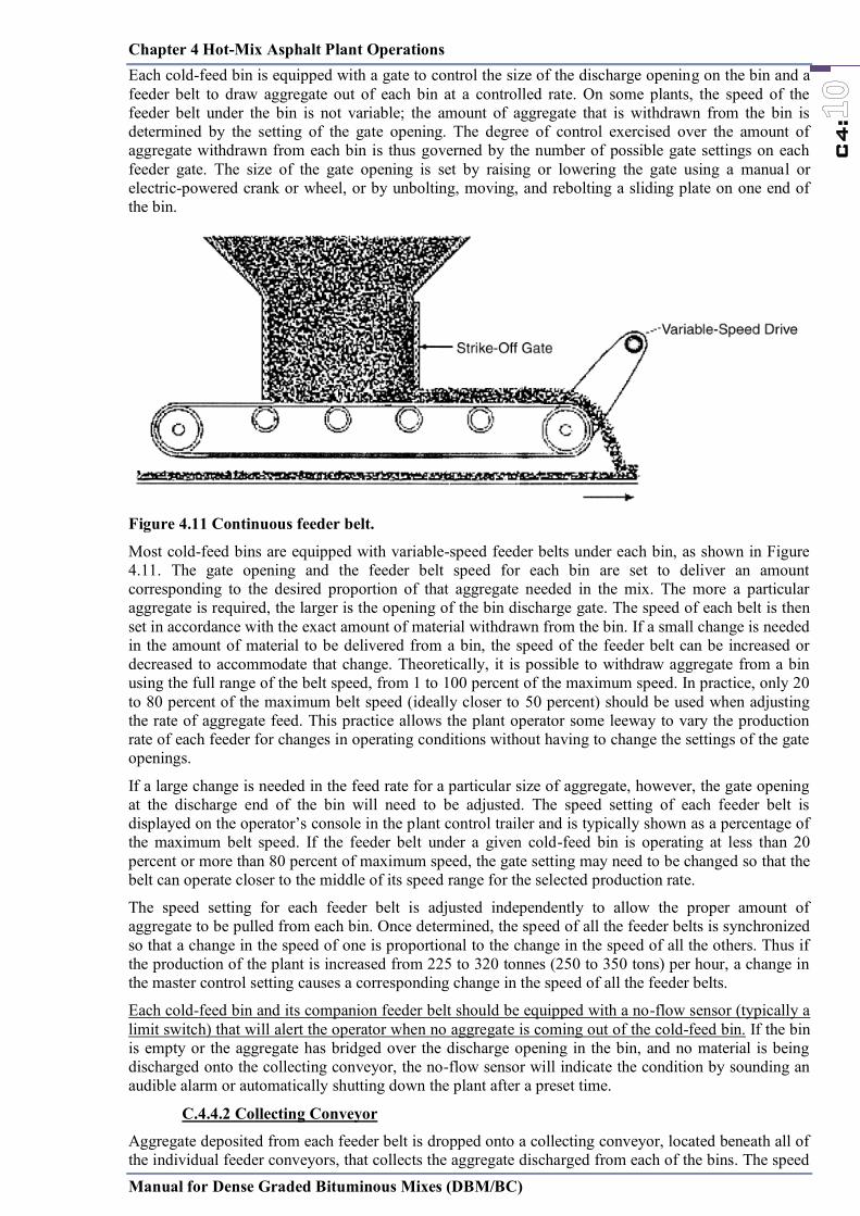
Chapter 4 Hot-Mix Asphalt Plant Operations
Manual for Dense Graded Bituminous Mixes (DBM/BC)
C4:
Each cold-feed bin is equipped with a gate to control the size of the discharge opening on the bin and a feeder belt to draw aggregate out of each bin at a controlled rate. On some plants, the speed of the feeder belt under the bin is not variable; the amount of aggregate that is withdrawn from the bin is determined by the setting of the gate opening. The degree of control exercised over the amount of aggregate withdrawn from each bin is thus governed by the number of possible gate settings on each feeder gate. The size of the gate opening is set by raising or lowering the gate using a manual or electric-powered crank or wheel, or by unbolting, moving, and rebolting a sliding plate on one end of the bin.
Figure 4.11 Continuous feeder belt.
Most cold-feed bins are equipped with variable-speed feeder belts under each bin, as shown in Figure 4.11. The gate opening and the feeder belt speed for each bin are set to deliver an amount corresponding to the desired proportion of that aggregate needed in the mix. The more a particular aggregate is required, the larger is the opening of the bin discharge gate. The speed of each belt is then set in accordance with the exact amount of material withdrawn from the bin. If a small change is needed in the amount of material to be delivered from a bin, the speed of the feeder belt can be increased or decreased to accommodate that change. Theoretically, it is possible to withdraw aggregate from a bin using the full range of the belt speed, from 1 to 100 percent of the maximum speed. In practice, only 20 to 80 percent of the maximum belt speed (ideally closer to 50 percent) should be used when adjusting the rate of aggregate feed. This practice allows the plant operator some leeway to vary the production rate of each feeder for changes in operating conditions without having to change the settings of the gate openings.
If a large change is needed in the feed rate for a particular size of aggregate, however, the gate opening at the discharge end of the bin will need to be adjusted. The speed setting of each feeder belt is displayed on the operator’s console in the plant control trailer and is typically shown as a percentage of the maximum belt speed. If the feeder belt under a given cold-feed bin is operating at less than 20 percent or more than 80 percent of maximum speed, the gate setting may need to be changed so that the belt can operate closer to the middle of its speed range for the selected production rate.
The speed setting for each feeder belt is adjusted independently to allow the proper amount of aggregate to be pulled from each bin. Once determined, the speed of all the feeder belts is synchronized so that a change in the speed of one is proportional to the change in the speed of all the others. Thus if the production of the plant is increased from 225 to 320 tonnes (250 to 350 tons) per hour, a change in the master control setting causes a corresponding change in the speed of all the feeder belts.
Each cold-feed bin and its companion feeder belt should be equipped with a no-flow sensor (typically a limit switch) that will alert the operator when no aggregate is coming out of the cold-feed bin. If the bin is empty or the aggregate has bridged over the discharge opening in the bin, and no material is being discharged onto the collecting conveyor, the no-flow sensor will indicate the condition by sounding an audible alarm or automatically shutting down the plant after a preset time.
C.4.4.2 Collecting Conveyor
Aggregate deposited from each feeder belt is dropped onto a collecting conveyor, located beneath all of the individual feeder conveyors, that collects the aggregate discharged from each of the bins. The speed
Chapter 4 Hot-Mix Asphalt Plant Operations
Manual for Dense Graded Bituminous Mixes (DBM/BC)
C4:
of the conveyor is constant. The amount of aggregate deposited on this conveyor is thus a function of the size of the gate opening and the speed of the feeder conveyor under each cold-feed bin.
To reduce the amount of buildup that may occur on this conveyor, particularly when the various aggregates are wet, the coarser aggregates should be placed on the belt first. The sand, which typically has the higher moisture content, may stick to the conveyor belt if placed on the belt first and may need to be continually removed. This may, in turn, affect the gradation of the aggregate in the mix.
C.4.4.3 Scalping Screens and Devices
On drum-mix plants it is desirable to insert a scalping screen into the cold-feed system to prevent oversized material from entering the mixer. Scalping can sometimes be accomplished by placing a screen over the top of the cold-feed bins. In many cases, however, this screen is only a grizzly type of device with relatively large openings. Because of the large volume of aggregate that is delivered at one time from the front-end loader to a cold-feed bin, a screen with small openings cannot properly handle the flow of aggregate from the loader bucket to the bin. Thus, scalping screens employed on top of the cold-feed bins are normally used only for the larger-sized coarse aggregate.
Figure 4.12 Typical arrangement of Scalping Screens and Devices
A scalping screen is used to remove larger-sized deleterious materials such as tree roots, vegetable matter, and clay lumps, as well as oversized aggregate, from the aggregate material. As shown in Figure 4.12, the scalping screen is most often placed somewhere between the end of the collecting conveyor and the drum. While it is not always necessary to pass quarry-processed aggregates through a scalping screen, it is good practice to do so to prevent any extraneous oversized material from entering the drum and thus the mix. A scalping screen should be used as part of the cold-feed system on a batch plant if the screens have been removed from the mixing tower or if the screens are bypassed. The openings in the scalping screen (the bottom screen if a double-deck screen is being used) are typically slightly larger than the maximum-sized aggregate used in the mix.
Scalping devices can be tailored to the needs of the individual plant. Typically only a single-deck scalping screen is used. Some plants, however, employ a double-deck scalping screen, which controls two different top-size aggregates without requiring changing of the screen. If both screens are being used, a flop gate at the lower end of the second screen is employed to redirect the aggregate caught on the bottom screen to the charging conveyor. The flop gate can be operated either manually or automatically. The openings in the screen can be either square or slotted. The advantage of the slotted screen is that a smaller screen area can be used to handle a given volume of material.
Collective Conveyor Scalping Screens
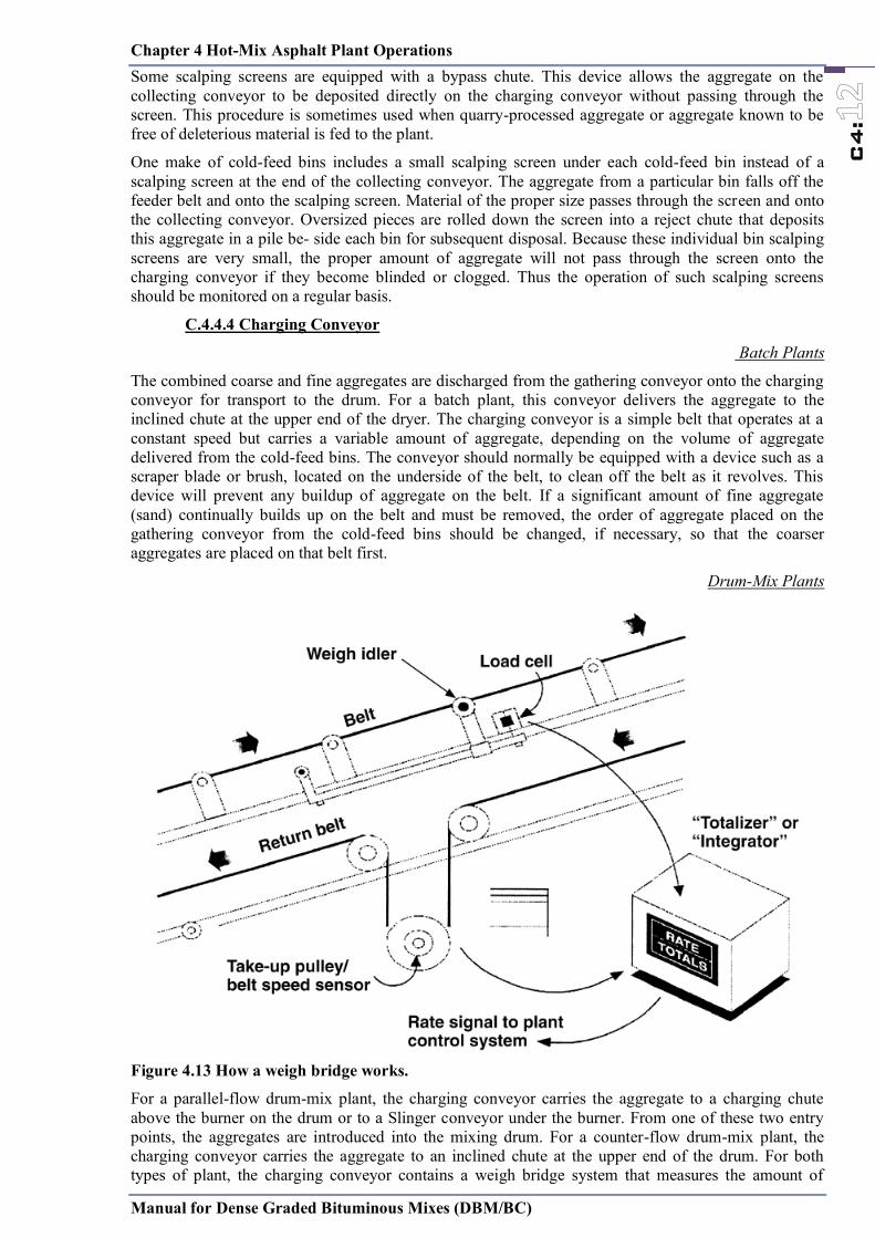
Chapter 4 Hot-Mix Asphalt Plant Operations
Manual for Dense Graded Bituminous Mixes (DBM/BC)
C4:
Some scalping screens are equipped with a bypass chute. This device allows the aggregate on the collecting conveyor to be deposited directly on the charging conveyor without passing through the screen. This procedure is sometimes used when quarry-processed aggregate or aggregate known to be free of deleterious material is fed to the plant.
One make of cold-feed bins includes a small scalping screen under each cold-feed bin instead of a scalping screen at the end of the collecting conveyor. The aggregate from a particular bin falls off the feeder belt and onto the scalping screen. Material of the proper size passes through the screen and onto the collecting conveyor. Oversized pieces are rolled down the screen into a reject chute that deposits this aggregate in a pile be- side each bin for subsequent disposal. Because these individual bin scalping screens are very small, the proper amount of aggregate will not pass through the screen onto the charging conveyor if they become blinded or clogged. Thus the operation of such scalping screens should be monitored on a regular basis.
C.4.4.4 Charging Conveyor
Batch Plants
The combined coarse and fine aggregates are discharged from the gathering conveyor onto the charging conveyor for transport to the drum. For a batch plant, this conveyor delivers the aggregate to the inclined chute at the upper end of the dryer. The charging conveyor is a simple belt that operates at a constant speed but carries a variable amount of aggregate, depending on the volume of aggregate delivered from the cold-feed bins. The conveyor should normally be equipped with a device such as a scraper blade or brush, located on the underside of the belt, to clean off the belt as it revolves. This device will prevent any buildup of aggregate on the belt. If a significant amount of fine aggregate (sand) continually builds up on the belt and must be removed, the order of aggregate placed on the gathering conveyor from the cold-feed bins should be changed, if necessary, so that the coarser aggregates are placed on that belt first.
Drum-Mix Plants
Figure 4.13 How a weigh bridge works.
For a parallel-flow drum-mix plant, the charging conveyor carries the aggregate to a charging chute above the burner on the drum or to a Slinger conveyor under the burner. From one of these two entry points, the aggregates are introduced into the mixing drum. For a counter-flow drum-mix plant, the charging conveyor carries the aggregate to an inclined chute at the upper end of the drum. For both types of plant, the charging conveyor contains a weigh bridge system that measures the amount of
Chapter 4 Hot-Mix Asphalt Plant Operations
Manual for Dense Graded Bituminous Mixes (DBM/BC)
C4:
aggregate, in tonnes (tons) per hour, being fed to the drum mixer. The weigh bridge, or belt scale, determines the weight of aggregate passing over the weigh idler. The charging conveyor operates at a constant speed that is independent of the speed of the other conveyors. The weigh bridge itself is located near the midpoint of the length of the charging conveyor.
A weigh idler, as shown in Figure 4.13, is the heart of the weigh bridge system. This idler is different from the fixed idlers on the conveyor frame. It is free to move and is attached to a load cell. As the aggregates pass over the weigh idler, the weight of the material is recorded as an electrical signal in the computer control system. The weight value by itself is meaningless, however, because it covers only an instant of time. Thus the charging conveyor is also equipped with a belt speed sensor, as shown in the figure. This device, usually located on the belt take up pulley, is a tachometer, which, coupled with the diameter of the pulley, is used to mea- sure the actual speed of the conveyor belt.
To obtain an accurate belt speed reading, it is essential that the charging conveyor belt be tight around the gravity takeup pulley, as shown in Figure 4.13. Any slippage of the belt over the speed sensor will result in an erroneous reading and an incorrect wet aggregate weight input to the drum mixer. Some conveyors are equipped with an air-actuated take up system, located on the tail shaft pulley, that operates in a manner similar to that of the gravity take up system. The purpose of this system is to keep the belt tight and eliminate the potential problem of inaccurate belt speed sensor readings.
The information from the weigh idler on the belt scale and from the belt speed sensor is combined to determine the actual weight of the aggregate in tonnes (tons) per hour. This value is the wet weight and includes the moisture in the aggregate. The wet weight is converted to dry weight by the plant computer so that the proper amount of Bitumen will be added to the mix. The average moisture content in the combined coarse and fine aggregates is input manually.
The moisture content of each of the aggregates being fed into the plant should be checked regularly and the average amount of moisture in the incoming aggregate determined. This determination should be made when- ever the moisture content of the aggregate stockpiles has changed, such as after it has rained, or a minimum of twice a day. This frequency can be reduced to a minimum of once a day during periods of consistent dry weather conditions. An erroneous moisture content input into the computer system will result in an inaccurate amount of binder material being added to the mix. If the actual moisture content of the incoming aggregate is higher than the value input to the computer, slightly less aggregate dry weight is actually being introduced into the drum, and a higher-than-desired amount of bitumen is being added to the aggregate. Conversely, if the actual moisture content of the incoming aggregate is lower than the value input to the computer, more aggregate is being introduced into the mixing drum, and a slightly lower binder content will result. The difference in the asphalt content, of course, will depend on the difference between the actual and input moisture values.
If the aggregates being carried on the belt are relatively dry, all the aggregates that pass over the weigh bridge will enter the drum. As discussed earlier, how- ever, if the moisture content of the aggregates is high, some of the fine aggregate may stick to the charging conveyor belt. This “extra” material will not be fed into the drum but will remain on the belt. If not removed by a scraper or brush, this material will continually be detected by the weigh bridge, and the plant computer will calculate a greater weight of aggregate entering the drum than is actually occurring. The computer will in turn signal the asphalt pump to deliver more Bitumen to the plant to allow for the additional aggregate. Thus the belt scraper or brush should be in place, continually cleaning the charging conveyor belt as it carries aggregate to the mixing drum. The amount and gradation of the fine aggregate removed by the scraper will change the gradation of HMA mix produced by the plant.
C.4.4.5 Mineral Feeding
The mineral filler can be added in one of several places. In some cases, it is placed in one of the plant cold feed bins and fed into the plant as an additional aggregate component. The filler can also be fed from a silo onto the aggregate gathering conveyor and then into the drum. In each case the material must be placed between the layers of other aggregates on the cold feed conveyors to prevent blowing or dusting of the mineral filler which would occur if the filler were spread on top of the coarse and fine aggregates.
Many drum mix plants are equipped to feed the mineral filler into the rear end of the plant through a filler feed line or auger system. A silo is employed to hold the filler and a vane feeder is used to proportion the material into the conveying pipe. An air or pneumatic system blows the filler into the drum where it is coated with the bitumen before it drops into the bottom of the drum.
Chapter 4 Hot-Mix Asphalt Plant Operations
Manual for Dense Graded Bituminous Mixes (DBM/BC)
C4:
C.4.4.6 Addition of Hydrated Lime
To reduce the occurrence of moisture damage in the HMA mix, hydrated lime is sometimes added to the mix at a rate of 1 to 2 percent by weight of aggregate. This material may be added in one of two different forms— as a dry powder or as a slurry. If a slurry is used, it is typically proportioned as one part hydrated lime to three parts water. The lime can be added by being mixed with the aggregate on the cold-feed belt or by being introduced into the rear of the drum, similar to what is done with a conventional mineral filler.
The dry lime or slurry is often added to the aggregate as it moves along the gathering conveyor or up the charging conveyor. The lime is normally placed on top of the aggregate and is then mixed with the aggregate either when the aggregate passes through the scalping screen, when it passes through a set of plows or mixing paddles on the belt, or in an in-line pugmill placed in the cold-feed system between the gathering conveyor and the charging conveyor. The amount of mixing of the lime that occurs as aggregate passes through the scalping screen, however, is normally not enough to ensure that all of the aggregate particles are adequately coated with lime. Therefore, this method should generally not be used. If the lime is to be mixed with the aggregate on the gathering or charging conveyor, a set of plow blades should be used to move the aggregate and the lime back and forth as the material moves up the belt. An even better way to ensure that the hydrated lime is properly mixed with the coarse and fine aggregate is to place a twin-shaft pugmill in the cold-feed system. This latter method distributes the lime more uniformly throughout the aggregate particles.
C.4.4.7 Calibration
The rate of aggregate flow from each cold-feed bin should be determined to ensure that the proper proportion of each aggregate is being delivered from the bin to the plant, so that the mix will have the proper gradation. The method used to calibrate the cold-feed bins depends on the type of plant being used and on the type of feeder belt under each bin.
Each cold-feed bin should be calibrated at a flow volume that will be within the range of material to be delivered from the bin during mix production. Ideally, the bin should be checked at rates that are approximately equal to 20, 50, and 80 percent of the estimated operational flow rate.
If a cold-feed bin is equipped with a constant-speed feeder belt, the only way to change the amount of aggregate delivered from the bin is to vary the size of the gate opening. In this case, the size of the gate opening at which the calibration procedure is conducted depends on the proportion of aggregate to be drawn out of the bin. If, according to the mix design information, 25 percent of the total amount of aggregate in the asphalt mix should come out of a given bin, that bin should be calibrated at the gate opening size that will typically provide this rate of flow. In addition, the calibration procedure should be completed at both the next-largest and next-smallest gate settings to allow for small changes in production rate. If significant changes in production rate are anticipated, the cold-feed bins should be calibrated at whatever gate openings are needed to provide the proper amount of that size of aggregate to the plant.
Many cold-feed bins on batch plants and the vast majority of the cold-feed bins on both parallel-flow and counter-flow drum-mix plants are equipped with a variable-speed feeder belt in addition to a means of changing the size of the gate opening under the bin. The gate opening on the cold-feed bin should be set at that level which will deliver the proper amount of aggregate for the desired plant production rate. In addition, the bin should be calibrated at three different feeder belt speeds: 20, 50, and 80 percent of the range of speed of the feeder belt. The optimum operating condition is for the cold-feed bin to provide the proper amount of aggregate from the preset gate opening with the feeder belt operating at approximately 50 percent of its maximum speed. Doing so allows the plant operator some latitude to increase or decrease the production rate of the plant without having to change the setting of the gate opening at the bottom of the cold-feed bins.
The calibration of each cold-feed bin is accomplished by drawing aggregate out of a bin for a specific period of time and determining the weight of the aggregate delivered during that time. In most cases, a truck’s empty (tare) weight is determined. Aggregate is withdrawn from the cold-feed bin and delivered, usually by means of a diverter chute on the charging conveyor, into the truck. After a set period of time, the flow of the aggregate is stopped, and the truck is weighed to determine the amount of aggregate delivered. For cold-feed bins equipped with only a constant-speed feeder belt, the weighing process is accomplished for a variety of gate opening settings. For cold-feed bins that are
Chapter 4 Hot-Mix Asphalt Plant Operations
Manual for Dense Graded Bituminous Mixes (DBM/BC)
C4:
equipped with variable-speed feeder belts, the calibration process may be repeated at different gate opening settings, with at least three different belt speeds per gate opening.
On a drum-mix plant, the weigh bridge must also be calibrated. This is accomplished by running aggregate over the charging conveyor and thus the weigh idler for a given period of time. Instead of being delivered to the drum mixer, the aggregate is diverted into an empty (tared) truck. After the selected time period has passed, the aggregate flow is terminated, and the truck is weighed to determine the amount of aggregate delivered. The weight thus determined is compared with the weight of aggregate calculated by the plant computer system. The two weights should be within the tolerance band set by the agency and typically within 1.0 percent of each other (assuming that the weigh bridge and the truck scale are both accurate to 0.5 percent). It must be noted that both methods used to weigh the material—the conveyor weigh bridge and the truck scale—must usually meet a tolerance of 0.5 percent of the true weight. Since one weight is being compared against the other and each has a tolerance of 0.5 percent, the two weights should be within 1.0 percent of each other.
For many drum-mix plants, the weigh bridge should be calibrated at a production rate that is near the estimated normal production rate for the plant. If the drum mixer is going to run at 90 percent of capacity, the calibration of the weigh bridge should be completed at three production rates: 70, 85, and 100 percent of capacity. This calibration, however, will probably not be correct if the plant is run at a much lower capacity, such as 60 percent. In this case, the calibration procedure should be repeated at the lower production rate (bracketing the estimated rate with one rate above and one rate below the most probable production level).
Because of the differences in the operating procedures of different makes and models of cold-feed bins and asphalt plants, it is difficult to generalize the exact calibration procedure to use. The calibration instructions provided with the plant should be followed.
C4.5: Bitumen Supply System
The Bitumen supply system consists of two major components. The first comprises one or more tanks used to store the Bitumen until it is needed by the mixing plant. The second is a pump and meter system used to draw Bitumen from the storage tank in proportion to the amount of aggregate being delivered to the batch plant pugmill or drum mixer.
C.4.5.1 Storage Tanks
All Bitumen storage tanks must be heated to maintain the correct temperature of the Bitumen so its viscosity will be low enough that it can be pumped and mixed with the heated and dried aggregate. Most Bitumen storage tanks are heated by a hot-oil system and are equipped with a small heater to heat and maintain the temperature of the oil. The hot oil is circulated through a series of coils inside the storage tank, and the heat is then transferred from the oil, through the coils, to the bitumen. This heat transfer process reduces the viscosity of the bitumen, causing it to flow upward and circulate or roll, and causing new, lower-temperature Bitumen to come in contact with the heating oils. Thus the hot-oil system, through a set of thermocouples and solenoid valves, maintains the proper temperature of the bitumen, generally in the range of 150°C to 180°C, depending on the grade and type of Bitumen being used.
Another common approach is to use electric heating elements to heat the asphalt tanks directly. Heating elements that can be removed for servicing are submerged directly into the tank. Scavenger coils may be installed in the asphalt tank to heat oil for asphalt lines and other parts of the plant requiring heat.
A less commonly used, much older style of Bitumen storage tank is the direct-fired tank. In this sys- tem, the Bitumen is heated by direct heat ex- change from the combustion source, through a series of heat tubes, to the bitumen. Care needs to be used with this type of tank to prevent overheating of the bitumen immediately adjacent to the heat tubes.
All storage tanks should be completely insulated and heated, and all the lines for both Bitumen and heating oil should be insulated to prevent loss of heat. Both the line used to fill the tank from the bitumen transport truck or railcar and the discharge line from the tank to the plant should be located near the bottom of the tank. The return line from the pump should be located so that the Bitumen enters the tank at a level beneath the surface of the Bitumen stored in the tank and does not fall through the air. This practice reduces the oxidation of the Bitumen during the circulation process.
Chapter 4 Hot-Mix Asphalt Plant Operations
Manual for Dense Graded Bituminous Mixes (DBM/BC)
C4:
On most asphalt storage tanks, the discharge line to the batch or drum-mix plant is located at a point closest to the plant to minimize the amount of pipe required. The return line for the Bitumen not used by the plant (depending on the particular plant pump and meter setup, as discussed below) is typically located on the same end of the storage tank. If it is desired to circulate the contents of the tank in order to keep the material blended, the return line should be relocated to the opposite end of the tank. Otherwise, only the material located at the end of the tank that contains the discharge and return lines will be circulated.
If the HMA plant is equipped with more than one bitumen storage tank, the capability should exist to pump material from one tank to another. It is important that the plant operator know from which tank material is being pulled, especially if different grades or types of Bitumen are being stored in different tanks. All Bitumen storage tanks contain a “heel” of material at the bottom of the tank. This material, located beneath the heating coils, usually does not circulate efficiently. The volume of material in the heel depends on the type and style of the storage tank, the location of the heating coils, and the amount of time since the tank was
last cleaned. It is recognized, however, that some as- phalt cement will typically remain in the bottom of an “empty” tank. Therefore, placing Bitumen of one type or grade into a tank that previously contained a dif- ferent type or grade can cause an alteration of the prop- erties of the Bitumen to the point that it no longer meets specifications.
The capacity of an Bitumen storage tank is a function of its diameter and length. The amount of material in the tank can be determined using a tank “stick.” The stick measures the distance from the top of the dome or the top of the tank down to the level of the bitumen in the tank (the point at which the tank stick just touches the top of the material). This distance is noted, and the amount of Bitumen in the tank below this level is determined from the tank manufacturer’s calibration chart.
When Bitumen is delivered from a transport vehicle into a storage tank, it is important to ensure either that the tank is clean or that it already contains the same type of material as that being pumped into the tank. If it is empty at the time the new material is being added, the tank should be checked to ensure that no water has accumulated in the bottom. If Bitumen is loaded on top of an asphalt emulsion or on top of a layer of water in the tank, violent foaming of the Bitumen may occur, creating a serious safety problem. Care should be taken to ensure that all valves are in the proper position to prevent pressure from building up in the lines and causing an explosion.
Most bitumen storage tanks are horizontal. Increasingly, however, vertical tanks are being used. Vertical tanks minimize separation of modifier in Bitumen and result in less overall area needed for storage.
C.4.5.2 Pump and Meter System
Batch Plants
Batch plants typically employ one of two systems to transfer Bitumen from the storage tank to the weigh bucket near the pugmill. The type of system used depends on the location of the return line whether one or two Bitumen lines are present from the pump to the weigh bucket.
In the single-line process, two lines extend from the storage tank to the pump, but only one line extends from the pump to the weigh bucket. The pump is a constant-volume, constant-speed unit that runs continuously. Bitumen is always being pulled from the storage tank through the pump and circulated back to the tank. When Bitumen is needed in the weigh bucket, a valve on the end of the line at the top of the weigh bucket opens, and material is discharged into that bucket. When the proper amount of Bitumen is in the bucket, as determined by weight, not volume, that valve is shut, and a pressure relief valve at the pump is opened. The Bitumen then passes through the pump, but is re-circulated back to the storage tank, in the second line, instead of being sent to the plant. A variation on this system allows the Bitumen to circulate through the pump itself in- stead of being returned back to the storage tank. In the dual-line process, one line is used to deliver bitumen to the weigh bucket, and the second line is used to return the “excess” Bitumen back to the storage tank. The Bitumen passes through the pump to a three-way valve at the weigh bucket. When bitumen is needed in the weigh bucket, the valve opens, and the material is discharged into the bucket. When the preselected weight is reached, the valve closes, and the bitumen is re-circulated in the second line back to the storage tank.
Because the amount of Bitumen used in almost all batch plants is measured by weight, no correction is needed for the temperature of the bitumen. On a few older batch plants, however, the amount of
Chapter 4 Hot-Mix Asphalt Plant Operations
Manual for Dense Graded Bituminous Mixes (DBM/BC)
C4:
Bitumen delivered is determined by volume. In this case, the amount of Bitumen delivered to the pugmill must be corrected in accordance with both the temperature and the specific gravity of the bitumen. This can be accomplished using the procedure given in ASTM Specification D4311.
Drum-Mix Plants
Most drum-mix plants employ one of three systems to pull the Bitumen from the storage tank, meter it, and pump it to the plant: (a) a variable-volume pump with a constant-speed motor, (b) a constant-volume pump with a variable-speed motor, or (c) a constant-volume pump with a constant-speed motor with a metering valve. The use of a particular pump and meter system is dependent on the make, model, and date of manufacture of the plant and the choice of the plant owner.
With a system that uses a variable-volume pump driven by a constant-speed motor, the amount of Bitumen pulled from the storage tank is controlled by changing the volume of Bitumen being pumped. The volume needed at the pump is determined by the plant computer in proportion to the amount of aggregate being fed into the plant. As the amount of aggregate entering the drum mixer increases, the volume of Bitumen pulled through the pump also increases. When the plant is not using bitumen, the material continually passes through the pump and meter and through a three-way valve that is set to circulate the bitumen back to the storage tank instead of to the plant.
A second system incorporates a fixed-displacement (constant-volume) pump driven by a variable-speed motor. The quantity of Bitumen delivered to the meter is varied by changing the speed of the motor. The amount of material sent to the plant is also dependent on the aggregate feed rate. A three-way valve in the system downstream of the meter allows the Bitumen to be re-circulated back to the tank when not needed by the plant.
The third system consists of a constant-volume pump driven by a constant-speed motor. In this arrangement, the same volume of Bitumen is pulled from the storage tank at all times. A proportioning valve is placed in the line between the pump and the Bitumen meter. The position of the valve determines the volume of material sent through the meter. The proportioning valve sends some of the Bitumen through the meter and the rest back through the re-circulating line to the storage tank. The system also has a valve downstream of the meter that allows the Bitumen sent through the meter to be re-circulated to the tank. This valve is used during the warm-up period for the meter and during the calibration process. Again, the position of the proportioning valve is determined by the rate of aggregate feed into the drum mixer, both of which are con- trolled by the plant computer.
With parallel-flow drum-mix plants, the bitumen line typically enters the drum from the rear, and the binder material is discharged into the drum at a point normally one-quarter to one-third the length of the drum, from the discharge end of the drum. With one type of counter flow drum-mix plant, the Bitumen pipe is placed in the mixing unit portion of the drum, behind or below the burner, and the binder material is added shortly after the aggregate passes out of the exhaust gas stream. In another type of counter-flow drum-mix plant, the bitumen is added to the heated aggregate in the outer drum away from the burner.
C.4.5.3. Temperature Compensation
Most bitumen meters measure the flow of bitumen by volume and convert this volume to weight using the specific gravity and temperature of the bitumen. Bitumen expands when heated. Thus the volume of Bitumen at 180 C will be somewhat greater than its volume at 150°C. This latter volume will be more than the volume at 15°C , which is the standard temperature for determining the volume of bitumen using conversion charts based on the specific gravity of the bitumen. If the specific gravity of the bitumen and its temperature are known, however, the volume measured at the elevated temperature can easily be converted to the standard volume at 15°C using the procedure given in ASTM Specification D4311.
The volume of Bitumen moving through the meter likewise changes with temperature. Some meters are set to measure the temperature of the Bitumen moving through the system and send that information, together with the volume data, to the plant computer. The specific gravity of the Bitumen is set manually on the controls. The computer then calculates the volume of Bitumen being fed into the plant at the standard temperature of 15°C and converts that amount to a weight that is displayed on the plant console.
On some meters, a temperature-compensating device is installed directly on the meter stand itself. As the temperature of the Bitumen changes, the meter senses the change and, on the basis of the specific

Chapter 4 Hot-Mix Asphalt Plant Operations
Manual for Dense Graded Bituminous Mixes (DBM/BC)
C4:
gravity of the bitumen, calculates the volume, at 15°C, passing through the meter. This corrected volume (and corresponding weight) is then sent to the plant console for display.
Regardless of the particular arrangement employed, the asphalt pump system must be capable of changing the volume of Bitumen passed through the meter in direct response to the demand of the aggregate supply. The response of the pump system must be directly related to the change in the amount of material mea- sured by the aggregate weigh bridge system. In addition, the volume of Bitumen measured at any given temperature must be converted to the volume at 15°C . At this standard reference temperature, the weight of the Bitumen can be determined in terms of tonnes (tons) of material per hour, as with the aggregate feed rate. The aggregate input and the weight of the bitumen provides the production rate for the drum mixer, in tonnes (tons) of HMA per hour. As production rates are adjusted, the asphalt pump system is timed so that the increase or decrease in Bitumen reaches the drum at the same time that the increased or decreased material flow reaches that point in the drum.
Another type of asphalt meter, called a “mass-flow meter,” measures the flow of bitumen by weight and, therefore, does not require temperature corrections
C.4.5.4. Calibration
The pump and meter system on a batch or drum-mix plant must be calibrated to ensure that the proper amount of Bitumen is being delivered to the mix. For a batch plant operation, the amount of Bitumen needed is measured by weight (although a few older batch plants measure the Bitumen by volume), with the Bitumen being placed in the plant weigh bucket. For a drum-mix plant, the amount of Bitumen is measured by volume as it is pumped through a meter into the rear of the drum.
For a drum mixer, the amount of Bitumen is calibrated by pumping the material into an empty container, the tare weight of which is known. Most often, an asphalt distributor truck is used for this purpose. The actual weight of the material delivered to the container is determined. The weight of the material indicated by the metering system as having been delivered is then determined by multiplying the corrected volume delivered from the meter totalizer by the specific gravity of the bitumen. With some systems, this calculation is done automatically. The actual weight is compared with that calculated by the metering system. To be in proper calibration, the values should be within the required tolerance band (typically 1.0 percent) for the bitumen supply system.
C.4.5.5. Antistrip materials
Where the proposed aggregate fails to pass the stripping test; and to improve the adhesion of the binder material to the surface of the aggregate and increase resistance to moisture damage, an approved anti-stripping agent (typically liquid antistrip additives) may be added to the binder in accordance with the manufacturer's instructions. The effectiveness of the proposed anti-stripping agent must be demonstrated by the Contractor, before approval by the Engineer
Table 4.1 Specification for Anti-stripping Agent Description Test method Requirements
Appearance Visual Dark Brown Liquid Specific Gravity at 270C IS 1448 0.85 ±0.1 Pour point IS 1448 Max 42 Flash point IS 1448 >1500C Moisture content IS 1448 Max 1.0 % Solubility in Diesel Oil in the Ratio 2:98 at 500 C
IS 6241 Min 95%
Stripping Value with Bitumen Containing 1 % Agent 400 C for 24 Hours
IS 6241 No Stripping
Under water coating test IS 6241 Min 95% Thermal stability at 1630C IS 6241 Stable
The Engineer may prescribe some additional periodic test such as “ under water coating test” stripping value for passive adhesive, Thermal stability, or solubility in high speed diesel” to confirm
Chapter 4 Hot-Mix Asphalt Plant Operations
Manual for Dense Graded Bituminous Mixes (DBM/BC)
C4:
that the adhesive agent being used is as claimed by the manufacture. The anti-stripping agent shall meet the requirements as given in Table 4.1;
Where required the adhesion agent should be of an approved type and should be used in accordance with the manufacturer’s instructions and as instructed by the Engineer.
The additive can be blended with the Bitumen at several different locations. It can be in-line mixed with the Bitumen as that material is pumped out of the tank truck or tank car and into the tank. It can also be added to the Bitumen in the tank, with the two different materials being circulated together before the treated Bitumen is sent to the drum mixer. The most common method, however is to add the liquid antistrip material to the bitumen, using an in-line blender, as the binder material is pumped from the storage tank to the rear of the drum-mix plant.
C4.6 Plant Trials
Once the laboratory job mix formula is approved, the Contractor should carry out plant trials to establish that the plant can produce a uniform mix conforming to the approved job mix formula. The permissible variations of the individual percentages of the various ingredients in the actual mix from the job mix formula to be used should be within the limits as specified in Table 6.1 and should remain within the gradation band. These variations are intended to apply to individual specimens taken for quality control tests.
Very few control tests for asphalt can be performed by the plant QC personnel. Penetration tests are sometimes performed in the plant laboratory to detect contamination during transport. It is good practice to randomly sample incoming loads of asphalt cement for future testing if necessary. The agency may also sample asphalt at the plant and run tests in the agency laboratory. In this case, samples stored on site are useful should any question arise about the quality of the asphalt.
Variations in the properties of asphalt are often missed because these properties are not frequently tested. This is a potential problem because if asphalt properties change from lot to lot, the mix properties and laydown characteristics of the hot mix may also change. These variations should be monitored if the plant QC technician reads and maintains a file of the certificates of tests submitted by the asphalt supplier.
The temperature of the produced asphalt must be closely monitored. Specifications set limits on the allowable temperature in the asphalt storage tanks. Overheating by the supplier or hauler should cause for rejection of the asphalt cement.

Chapter 5 Field Operation
Manual for Dense Graded Bituminous Mixes (DBM/BC)
C5:
C5.1 Paving equipment
Using proper equipment, placement techniques, and compaction in a hot mix asphalt paving project are critical to its success. A thorough understanding of proper paving practices is essential to the owner and agents in monitoring and inspecting the paving project.
C.5.1.1 Hauling equipment
Trucks used for hauling HMA should have clean, smooth, tight metal beds. It is important that the truck beds be relatively smooth without excessive indentations or depressions. These uneven areas provide areas for the truck bed release agent to accumulate and this could create problems with the placement of the HMA. Any debris from the previous load hauled should be removed.
Figure 5.1 Typical hauling unit
The inside of the truck box should be coated with an approved release agent. The minimum amount necessary should be used. Excessive release agent could create placement problems.
Petroleum products (fuel oil, diesel fuel, kerosene, gasoline) or solvents should not be used. These products can cause the PG binders to take on different and undesirable properties causing soft spots where potholes will occur. In addition, use of these petroleum products can contribute to environmental problems.
Trucks should be equipped with waterproof covers that totally cover the load of HMA. Flexible covers should overlap the sideboards and tailgate of the truck. The front of the tarp should be attached to prevent wind from getting under the tarp during the transport. Even for the shortest hauls and warmest days, tarps should be used.
C.5.1.2 HMA pavers
HMA pavers should be self–propelled with a receiving hopper, transfer system such as feed chains, and an activated screed. Skid boxes that are pulled by another piece of equipment, usually the truck loaded with the HMA, are not generally acceptable for highway paving. The paver should be able to spread the HMA in lane widths, to the proper grade and slope, and to the desired thickness. If it is necessary to extend the screed for main line placement, screed extensions should be of the same design as the main screed. The capacity of the receiving hopper shall be of sufficient capacity to allow a uniform layer to be placed. The paver should be equipped with automatic flow controls that will deposit the HMA mixture uniformly in front of the screed without segregation. The paving unit should be capable of moving ahead at a speed that will result in a smooth uniform placement of the HMA mixture.
Chapter 5 Field Operation
Manual for Dense Graded Bituminous Mixes (DBM/BC)
C5:
C.5.1.3. Rollers
There are three basic types of rollers used to compact HMA pavements: vibratory, static steel wheel, and pneumatic (rubber) tired rollers. It is important that all rollers are in good mechanical condition, free from oil leaks, and able to slow, stop, and reverse direction smoothly without backlash.
Vibratory rollers should be specifically designed for HMA compaction. They should be equipped with a speedometer to indicate the roller speed.
Static steel wheeled rollers should be self–propelled and generally about 8 to 10 tons in weight. Vibratory rollers run in a static mode and can be used as a static steel wheel roller.
Pneumatic (rubber) tired rollers should be self–propelled and consist of two axles on which multiple pneumatic tired wheels are mounted so that the front and rear wheels do not follow in the same tracks. The wheels should be mounted so that they oscillate, and the Figure 5.2 Vibratory roller tires must be smooth and the same size, have the same ply, and the same tire pressure.
Figure 5.2 Vibratory roller (Left) & Rubber tired roller(Right)
5.2 Site Trials
Before commencing execution and from time to time as may be considered necessary by the Engineer the Contractor should carry out trial sections at location instructed by the Engineer to demonstrate to the Engineer that this his surfacing operation is capable of executing the works in accordance with the Specification requirement.
Full scale laying and compacting site trials should be carried out by the Contractor on all asphalt pavement materials proposed for the works using the construction plant and methods proposed by the Contractor for construction the works.
The Contractor should allow in his/her program for conducting site trials and for carrying out the appropriate tests on them. The trial on any pavement layer should be undertaken at least 21 days ahead of the Contractor proposing to commence the full scale work on that layer.
The following listing of placement controls should be closely established during the trial by the contractor:
Application of tack coat Rate of HMA delivery Paver speed Paver adjustments Grade control Thickness control
Chapter 5 Field Operation
Manual for Dense Graded Bituminous Mixes (DBM/BC)
C5:
Density control Temperature of air and mixture Roller type Rolling pattern and coverage Roller speed Control of yield thickness Control of smoothness
Each trials area shall be at least 100 metres long to the full construction width and depth for the material. It may form part of the Works provided it complies with the Specification. Any areas which do not comply with this Specification shall be removed.
The Contractor shall compact each section of trial over the range of compact effort the Contractor is proposing. The following data shall be recorded for each level of compact effort at each site trial.
(i) The composition and grading of the material including the bitumen content and type and grade of bitumen used.
(ii) The moisture content of aggregate in the asphalt plant hot bins.
(iii) The temperature of bitumen and aggregate immediately prior to entering the mixer, the temperatures of the mix on discharge from the mixer and the temperature of the mix on commencement of laying, on commencement of compaction and on completion of compaction.
(iv) The type, size, mass, width of roll, number of wheels, wheel load, tyre pressures, frequency of vibration and the number of passes of the compaction equipment, as appropriate for the type of roller.
(v) The target voids and other target properties of the mix together with the results of the laboratory tests on the mix.
(vi) The density and voids achieved.
(vii) The compacted thickness of the layer.
(viii) Any other relevant information as directed by the Engineer.
At least eight sets of tests shall be made by the Contractor on each 100 metres of trial for each level of compact effort and provided all eight sets of results over the range of compact effort proposed by the Contractor meet the specified requirements for the material then the site trial shall be deemed successful. The above data recorded in the trial shall become the agreed basis on which the particular material shall be provided and processed to achieve the specified requirements.
The density of the finished paving layer should be determined by taking cores, no sooner than 24 hours after laying, or by other approved method. The compacted layers of Dense Graded Bituminous Macadam (DBM) /AC should have a minimum field density equal to or more than 92% of the density based on theoretical maximum specific gravity (Gmm) obtained on the day of compaction in accordance with ASTM D 2041.
Once the laying trials have been approved, the same plant and methodology should be applied to the laying of the material on the project, and no variation of either shall be acceptable, unless approved in writing by the Engineer, who may at his discretion require further laying trials.
5.3 Weather limitations
It is not desirable to place HMA on wet surfaces or in weather conditions that would inhibit the proper placement and compaction of the HMA mixture. In case of following situation , laying should be suspended:
i. In presence of standing water on the surface; ii. When rain is imminent, and during rains, fog or dust storm; iii. When the base/binder course is damp;
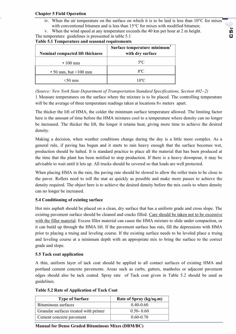
Chapter 5 Field Operation
Manual for Dense Graded Bituminous Mixes (DBM/BC)
C5:
iv. When the air temperature on the surface on which it is to be laid is less than 10°C for mixes with conventional bitumen and is less than 15°C for mixes with modified bitumen;
v. When the wind speed at any temperature exceeds the 40 km per hour at 2 m height. The temperature guidelines is pressented in table 5.1 Table 5.1 Temperature and seasonal requirements
Nominal compacted lift thickness Surface temperature minimum1
with dry surface
• 100 mm 5ºC
• 50 mm, but <100 mm 8ºC
<50 mm 10ºC (Source: New York State Department of Transportation Standard Specifications, Section 402–2) 1 Measure temperatures on the surface where the mixture is to be placed. The controlling temperature will be the average of three temperature readings taken at locations 8± meters apart.
The thicker the lift of HMA, the colder the minimum surface temperature allowed. The limiting factor here is the amount of time before the HMA mixtures cool to a temperature where density can no longer be increased. The thicker the lift, the longer it retains heat, giving more time to achieve the desired density.
Making a decision, when weather conditions change during the day is a little more complex. As a general rule, if paving has begun and it starts to rain heavy enough that the surface becomes wet, production should be halted. It is standard practice to place all the material that has been produced at the time that the plant has been notified to stop production. If there is a heavy downpour, it may be advisable to wait until it lets up. All trucks should be covered so that loads are well protected.
When placing HMA in the rain, the paving rate should be slowed to allow the roller train to be close to the paver. Rollers need to roll the mat as quickly as possible and make more passes to achieve the density required. The object here is to achieve the desired density before the mix cools to where density can no longer be increased.
5.4 Conditioning of existing surface
Hot mix asphalt should be placed on a clean, dry surface that has a uniform grade and cross slope. The existing pavement surface should be cleaned and cracks filled. Care should be taken not to be excessive with the filler material. Excess filler material can cause the HMA mixture to slide under compaction, or it can build up through the HMA lift. If the pavement surface has ruts, fill the depressions with HMA prior to placing a truing and leveling course. If the existing surface needs to be leveled place a truing and leveling course at a minimum depth with an appropriate mix to bring the surface to the correct grade and slope.
5.5 Tack coat application
A thin, uniform layer of tack coat should be applied to all contact surfaces of existing HMA and portland cement concrete pavements. Areas such as curbs, gutters, manholes or adjacent pavement edges should also be tack coated. Spray rate of Tack coat given in Table 5.2 should be used as guidelines.
Table 5.2 Rate of Application of Tack Coat
Type of Surface Rate of Spray (kg/sq.m) Bituminous surfaces 0.40-0.60 Granular surfaces treated with primer 0.50- 0.60 Cement concrete pavement 0.60-0.70
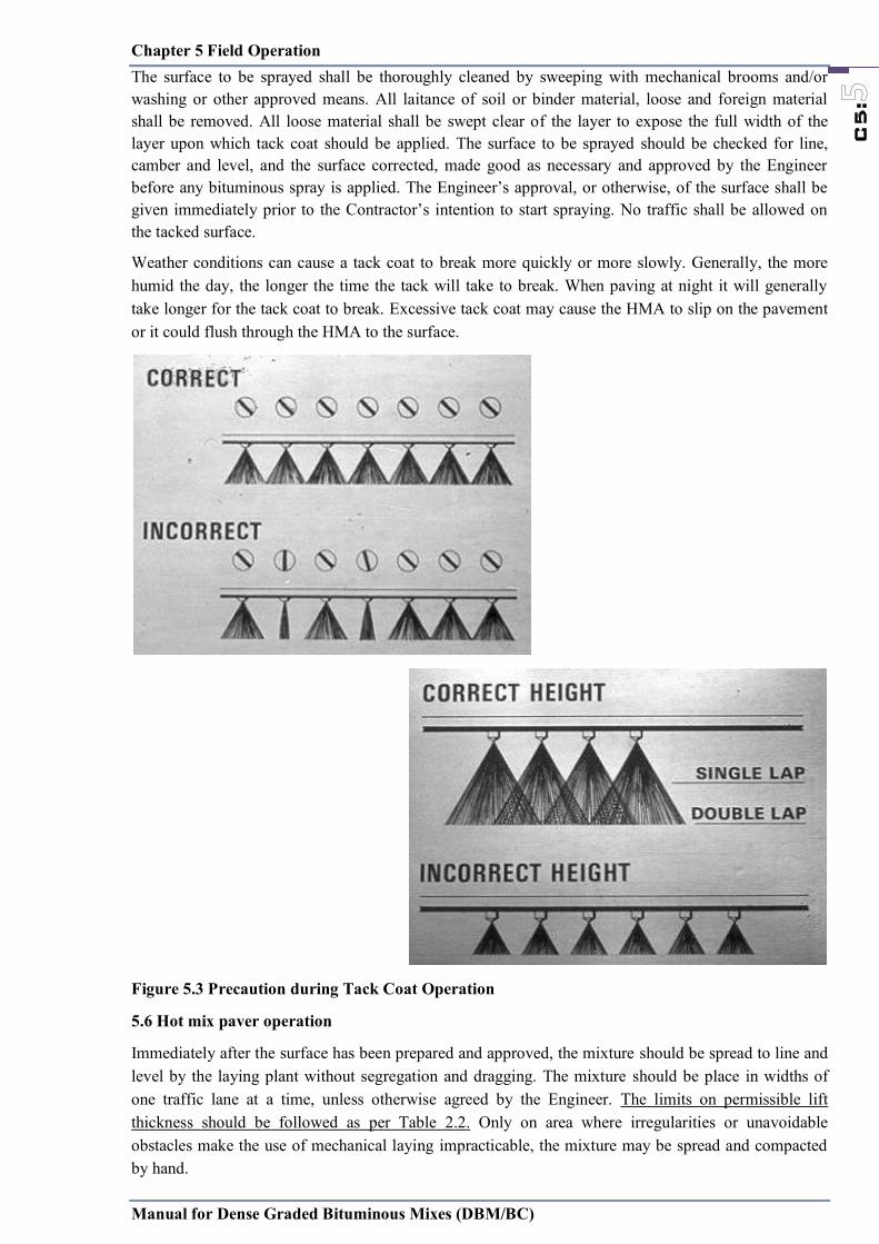
Chapter 5 Field Operation
Manual for Dense Graded Bituminous Mixes (DBM/BC)
C5:
The surface to be sprayed shall be thoroughly cleaned by sweeping with mechanical brooms and/or washing or other approved means. All laitance of soil or binder material, loose and foreign material shall be removed. All loose material shall be swept clear of the layer to expose the full width of the layer upon which tack coat should be applied. The surface to be sprayed should be checked for line, camber and level, and the surface corrected, made good as necessary and approved by the Engineer before any bituminous spray is applied. The Engineer’s approval, or otherwise, of the surface shall be given immediately prior to the Contractor’s intention to start spraying. No traffic shall be allowed on the tacked surface.
Weather conditions can cause a tack coat to break more quickly or more slowly. Generally, the more humid the day, the longer the time the tack will take to break. When paving at night it will generally take longer for the tack coat to break. Excessive tack coat may cause the HMA to slip on the pavement or it could flush through the HMA to the surface.
Figure 5.3 Precaution during Tack Coat Operation
5.6 Hot mix paver operation
Immediately after the surface has been prepared and approved, the mixture should be spread to line and level by the laying plant without segregation and dragging. The mixture should be place in widths of one traffic lane at a time, unless otherwise agreed by the Engineer. The limits on permissible lift thickness should be followed as per Table 2.2. Only on area where irregularities or unavoidable obstacles make the use of mechanical laying impracticable, the mixture may be spread and compacted by hand.
Chapter 5 Field Operation
Manual for Dense Graded Bituminous Mixes (DBM/BC)
C5:
The HMA is deposited directly into the paver hopper by the hauling unit. The truck driver should back his truck and stop just short of the paver. Once stopped, the brake should be released so that when the paver comes forward and picks up the truck, there is as little disturbance as possible.
When a tandem axle or tri–axle is used the box should be raised enough to “break” the load before the tailgate is released. This is done so that the mix slides from the truck to the paver hopper in a mass and avoids segregation. It is best to keep the hopper full and not let it run out of material. The less opportunity the HMA has to “break and run,” the less chance for segregation to occur. The same concept should be followed with live bottom trucks. Avoid dribbling the mix into the hopper.
The best way to end up with a high quality smooth pavement is to place the mat at a consistent rate, without stopping the paver. This is not always possible, but the closer you can come to this ideal, the better the end result.
Figure 5.4 Mass movement of hot mix asphalt
The tendency of most paving operations is to unload a truck of HMA as quickly as possible. It is much better to adjust the speed of the paver to try to allow for a truck to always be waiting to unload. To most paving crews this seems to be painfully slow. It will require discipline to maintain a consistent, steady pace.
The level of material in front of the screed should be kept at a constant temperature and level. The appropriate level should be about to the middle of the auger. Maintaining this constant head or level of material is a big factor in the resultant smoothness of the pavement.
The screed of the paver is used to strike off the HMA to the proper depth and grade. Most pavers today have screeds that can be controlled by automation as well as manually. Under manual control the thickness is controlled by cranks or screws. As the mix passes under the screed the operator can adjust the angle of attack of each side of the screed to change the depth of the mat. The most common mistake made by screed operators is to constantly adjust the screed angle causing the depth to change accordingly. Since it takes about the length of the paver for any change to show up at the screed, the operator tends to chase the screed changes up and down.
Automated operation of the screed eliminates this problem. Automated screed controls keep the elevation of the screed at a predetermined elevation relative to a reference such as a long “ski.” As the
Larger dumping angle ensures mass discharge
Mass movement

Chapter 5 Field Operation
Manual for Dense Graded Bituminous Mixes (DBM/BC)
C5:
ski moves over the existing grade, the deviations in the surface are averaged. The screed is adjusted based on this moving average.
Generally, automated control of the screed will produce a smoother pavement than manual control. However, because the automatic control levels out the pavement over the length of the ski, the thickness will vary. This almost always results in a higher yield than neat line calculation would indicate. If your project is restricted by a predetermined quantity of HMA, it is important to closely monitor the yield.
Segregation
HMA producers and contractors need to be especially vigilant in watching for segregation throughout the whole process of the project. Segregation can happen any time the HMA is moved from one place to another. This includes the manufacture and loading of the material at the plant. At the paving operation, segregation can occur in the paver hopper when the material is dumped into the paver, or at any location in the feed system, and in the augers.
Constant alertness to possible segregation by all members of the paving crew and the owners’ agents can help to overcome segregation problems. Even though material has been successfully processed through the cold feed bin, through the plant, through the surge or storage bin, then uniformly loaded on the truck, segregation can still occur in the paver. Improper operation of a paver can cause segregation in varying degrees. Here are suggestions that should be considered when segregation occurs at the paver.
a. Do not completely empty the hopper between each truck load. Coarse material tends to roll to each side of the truck bed and thus roll directly into the wings of the hopper. By leaving material in the hopper the coarse material has a better chance of being mixed with finer material before being placed on the road.
b. Dump hopper wings only as required to level the material load in the hopper. Dumping eliminates the valleys in the material bed, thereby minimizing rolling that occurs when unloading. It allows the truck tailgate to swing open fully to flood the hopper with mix.
c. Dump the truck so as to flood the hopper. With the hopper as full as possible, material tends to be conveyed out from under the truck and minimizes the tendency to roll as it is dumped into the hopper.
d. Open hopper gates as wide as possible to insure that the augers are full. By closing the gates and starving the augers for mix, fine material will drop directly on the ground causing coarse material to be augered to each side.
e. Run the paver as continuously as possible. Start and stop only as necessary. Adjust the paver speed to balance paver production with plant production.
f. Run augers continuously. Auger speed should be adjusted so that a continuous, slow only of material occurs. Augers that run at high speeds are cycling on and off continuously and contribute signicantly to segregation at the paver.
g. If augers are running too fast, the center of the mat will be decient of material and this will generally result in a coarse strip, Baffle plates, can also prevent coarse materials from rolling in front of the auger gear box and causing center line segregation. With the installation of the baffles, the augers then divert material uniformly to the center.
h. If the outer edges of the paver auger are decient of material, coarse strips along the outsides can occur as the coarse aggregate rolls to the outsides.
i. If possible, adjust paver extensions so that the paver pulls the same amount of material from each side of the hopper. If one side is pulling more material, a valley will form in that side of the paver hopper,
Chapter 5 Field Operation
Manual for Dense Graded Bituminous Mixes (DBM/BC)
C5:
causing segregation to occur in sensitive mixes. If correction cannot be made by adjusting the extension, offset the truck slightly towards the side requiring more material to even out the material bed in the hopper.
j. Pavers without auger extensions can cause outside edge segregation. A segregation prone mix can segregate without auger extensions as the mix piles up at the end of the auger and the larger aggregate rolls off toward the outside edge of the road.
5.7 Hot mix compaction
Without a doubt, compaction is the most critical element in the durability of the HMA pavement. The amount of material passing the 74 µm (#200) sieve can have a dramatic effect on the compaction of a mix. A higher percentage of minus 74 µm (#200) material will generally make a mix more difficult to compact.
Immediately after the bituminous mixture has been spread, it should be thoroughly and uniformly compacted by rolling. The layer should be rolled when the mixture is in such a condition that rolling does not cause undue displacement or shoving.
The number, weight and type of rollers furnished should be sufficient to obtain required compaction while the mixture is in a workable condition. Initial rolling with a steel tandem of three-wheeled roller should follow the laying plant as closely as possible. The rollers should be operated with the drive roll nearest the laying plant, at a slow and uniform speed (not exceeding 5 km/h).
Figure 5.5 Recommended rolling pattern
Intermediate rolling with a pneumatic tyre or vibratory roller should follow immediately. Final rolling with a steel wheeled roller should be used to eliminate marks from previous rolling. To prevent adhesion of the mixture to the rollers, the wheels should be kept lightly moistened with water. In areas too small for the roller, a vibrating rate plate compactor or a hand tamper should be used to achieve the specified compaction. The recommended rolling pattern is as per figure 5.5. Every pass of the roller should proceed straight into the compacted mix and return in the same path. After the required passes are completed, the roller should move to the outside of the pavement on cooled material and repeat the procedure.
Basis rules for rolling:
o Decelerate and accelerate slowly and smoothly whenever switching direction. This is to avoid shoving the mat.
o Shut off vibration when slowing the roller to a stop, and start it again when the roller is moving over 0.8 km/hr.
o For vibratory rollers, make sure to operate at a speed that will achieve at least 10 impacts per 300 mm (one foot) of travel.
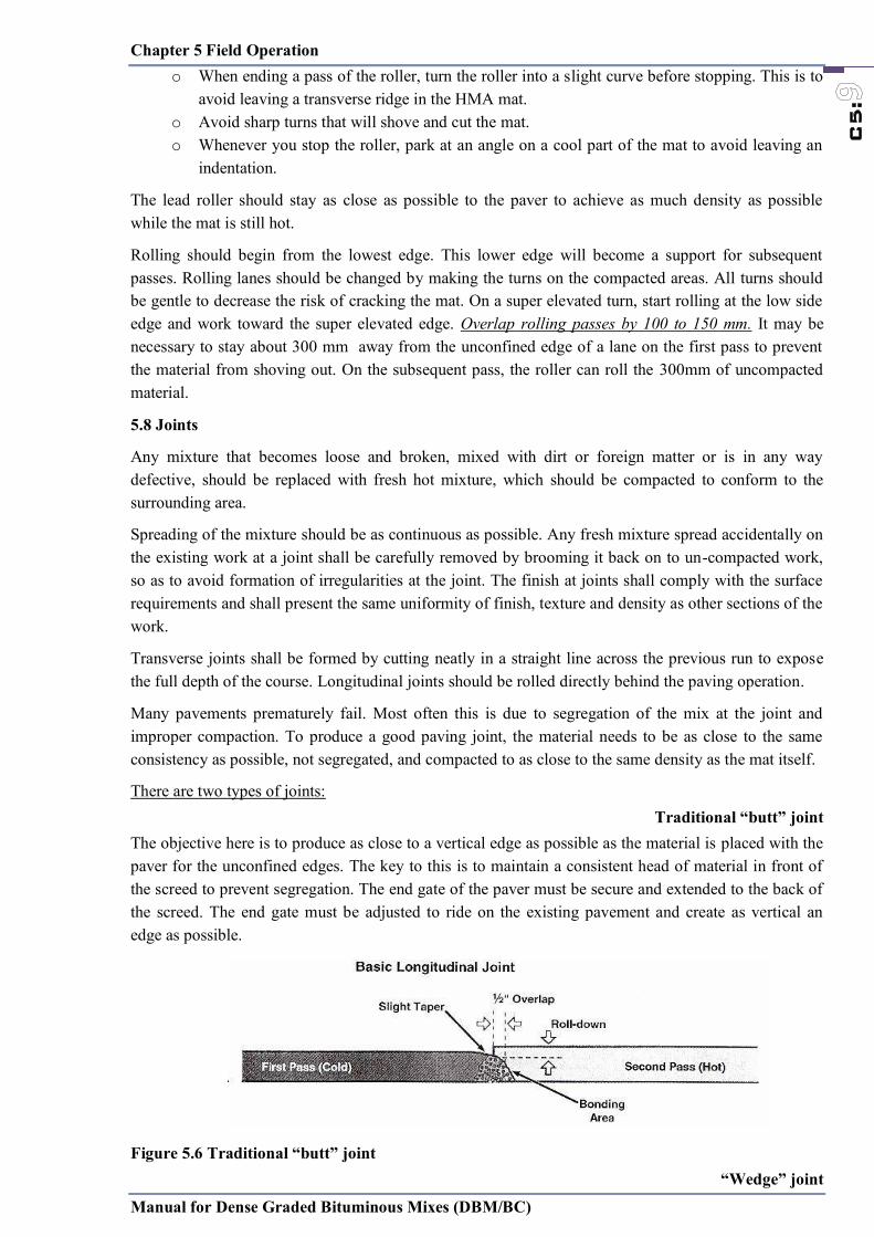
Chapter 5 Field Operation
Manual for Dense Graded Bituminous Mixes (DBM/BC)
C5:
o When ending a pass of the roller, turn the roller into a slight curve before stopping. This is to avoid leaving a transverse ridge in the HMA mat.
o Avoid sharp turns that will shove and cut the mat. o Whenever you stop the roller, park at an angle on a cool part of the mat to avoid leaving an
indentation.
The lead roller should stay as close as possible to the paver to achieve as much density as possible while the mat is still hot.
Rolling should begin from the lowest edge. This lower edge will become a support for subsequent passes. Rolling lanes should be changed by making the turns on the compacted areas. All turns should be gentle to decrease the risk of cracking the mat. On a super elevated turn, start rolling at the low side edge and work toward the super elevated edge. Overlap rolling passes by 100 to 150 mm. It may be necessary to stay about 300 mm away from the unconfined edge of a lane on the first pass to prevent the material from shoving out. On the subsequent pass, the roller can roll the 300mm of uncompacted material.
5.8 Joints
Any mixture that becomes loose and broken, mixed with dirt or foreign matter or is in any way defective, should be replaced with fresh hot mixture, which should be compacted to conform to the surrounding area.
Spreading of the mixture should be as continuous as possible. Any fresh mixture spread accidentally on the existing work at a joint shall be carefully removed by brooming it back on to un-compacted work, so as to avoid formation of irregularities at the joint. The finish at joints shall comply with the surface requirements and shall present the same uniformity of finish, texture and density as other sections of the work.
Transverse joints shall be formed by cutting neatly in a straight line across the previous run to expose the full depth of the course. Longitudinal joints should be rolled directly behind the paving operation.
Many pavements prematurely fail. Most often this is due to segregation of the mix at the joint and improper compaction. To produce a good paving joint, the material needs to be as close to the same consistency as possible, not segregated, and compacted to as close to the same density as the mat itself.
There are two types of joints: Traditional “butt” joint
The objective here is to produce as close to a vertical edge as possible as the material is placed with the paver for the unconfined edges. The key to this is to maintain a consistent head of material in front of the screed to prevent segregation. The end gate of the paver must be secure and extended to the back of the screed. The end gate must be adjusted to ride on the existing pavement and create as vertical an edge as possible.
Figure 5.6 Traditional “butt” joint “Wedge” joint
Chapter 5 Field Operation
Manual for Dense Graded Bituminous Mixes (DBM/BC)
C5:
In “wedge” joint, or tapered joint, the edge of the first pass is tapered over a 300mm width to produce the wedge. This is done by a tapered plate on the paver screed or with special screed extensions that extrudes the wedge and imparts some compaction to it. The second pass of the pavement extends slightly over the wedge. The heat of the overlying material helps to achieve the desired density at the joint. Figure 5.7 Notched wedge joint A modification of the wedge joint is the “notched” wedge joint. This technique leaves a vertical edge of about 25 mm at the top of the wedge. This gives the hot mat of the second pass a confining edge, and it also gives a vertical edge as a steering guide for the paver operator.
With both of these joint techniques the paver operator must steer a straight line while laying the first pass to make it easier to have the proper overlap and depth of material on the second pass. The joint face should be painted lightly with hot VG10 or similar grade bitumen just before the additional mixture is placed against it.
5.8.1 Joint compaction
There are two standard alternatives for joint compaction:
Figure 5.8 Rolling a longitudinal joint
Alternative A – The joint is compacted with the roller working on the cold lane and overlapping the hot lane by 100 to 200 mm . Vibration should not be used when most of the roller is on the cold lane. One of the disadvantages to this alternative is that the roller will be in the traffic lane when it makes its pass on the joint.
Alternative B – The joint is compacted with the roller working on the hot lane with a 100 to 200 mm overlap on the cold lane. When using this alternative, as the mat is rolled from the lower, outside first, a berm of uncompacted material about 150 mm wide can be left next to the cold mat. Then when the last pass is made, overlapping a few inches onto the cold mat, the berm material is compressed between the two compacted mats.
C5.9 Opening to Traffic
It should be ensured that the traffic is not allowed without the approval of the Engineer in writing, on the surface until the dense bituminous/AC layer has cooled to the ambient temperature.

Chapter 5 Field Operation
Manual for Dense Graded Bituminous Mixes (DBM/BC)
C5:
C5.1 Paving equipment
Using proper equipment, placement techniques, and compaction in a hot mix asphalt paving project are critical to its success. A thorough understanding of proper paving practices is essential to the owner and agents in monitoring and inspecting the paving project.
C.5.1.1 Hauling equipment
Trucks used for hauling HMA should have clean, smooth, tight metal beds. It is important that the truck beds be relatively smooth without excessive indentations or depressions. These uneven areas provide areas for the truck bed release agent to accumulate and this could create problems with the placement of the HMA. Any debris from the previous load hauled should be removed.
Figure 5.1 Typical hauling unit
The inside of the truck box should be coated with an approved release agent. The minimum amount necessary should be used. Excessive release agent could create placement problems.
Petroleum products (fuel oil, diesel fuel, kerosene, gasoline) or solvents should not be used. These products can cause the PG binders to take on different and undesirable properties causing soft spots where potholes will occur. In addition, use of these petroleum products can contribute to environmental problems.
Trucks should be equipped with waterproof covers that totally cover the load of HMA. Flexible covers should overlap the sideboards and tailgate of the truck. The front of the tarp should be attached to prevent wind from getting under the tarp during the transport. Even for the shortest hauls and warmest days, tarps should be used.
C.5.1.2 HMA pavers
HMA pavers should be self–propelled with a receiving hopper, transfer system such as feed chains, and an activated screed. Skid boxes that are pulled by another piece of equipment, usually the truck loaded with the HMA, are not generally acceptable for highway paving. The paver should be able to spread the HMA in lane widths, to the proper grade and slope, and to the desired thickness. If it is necessary to extend the screed for main line placement, screed extensions should be of the same design as the main screed. The capacity of the receiving hopper shall be of sufficient capacity to allow a uniform layer to be placed. The paver should be equipped with automatic flow controls that will deposit the HMA mixture uniformly in front of the screed without segregation. The paving unit should be capable of moving ahead at a speed that will result in a smooth uniform placement of the HMA mixture.
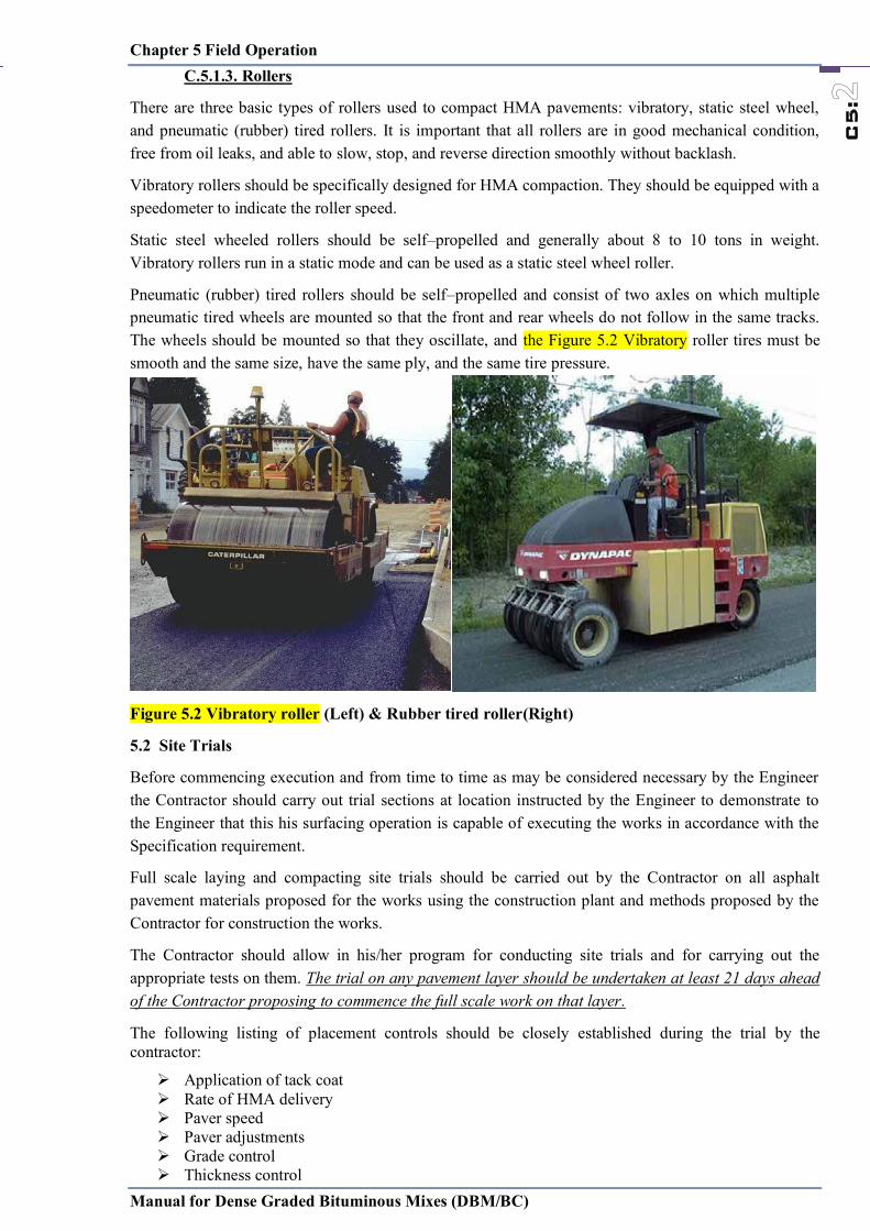
Chapter 5 Field Operation
Manual for Dense Graded Bituminous Mixes (DBM/BC)
C5:
C.5.1.3. Rollers
There are three basic types of rollers used to compact HMA pavements: vibratory, static steel wheel, and pneumatic (rubber) tired rollers. It is important that all rollers are in good mechanical condition, free from oil leaks, and able to slow, stop, and reverse direction smoothly without backlash.
Vibratory rollers should be specifically designed for HMA compaction. They should be equipped with a speedometer to indicate the roller speed.
Static steel wheeled rollers should be self–propelled and generally about 8 to 10 tons in weight. Vibratory rollers run in a static mode and can be used as a static steel wheel roller.
Pneumatic (rubber) tired rollers should be self–propelled and consist of two axles on which multiple pneumatic tired wheels are mounted so that the front and rear wheels do not follow in the same tracks. The wheels should be mounted so that they oscillate, and the Figure 5.2 Vibratory roller tires must be smooth and the same size, have the same ply, and the same tire pressure.
Figure 5.2 Vibratory roller (Left) & Rubber tired roller(Right)
5.2 Site Trials
Before commencing execution and from time to time as may be considered necessary by the Engineer the Contractor should carry out trial sections at location instructed by the Engineer to demonstrate to the Engineer that this his surfacing operation is capable of executing the works in accordance with the Specification requirement.
Full scale laying and compacting site trials should be carried out by the Contractor on all asphalt pavement materials proposed for the works using the construction plant and methods proposed by the Contractor for construction the works.
The Contractor should allow in his/her program for conducting site trials and for carrying out the appropriate tests on them. The trial on any pavement layer should be undertaken at least 21 days ahead of the Contractor proposing to commence the full scale work on that layer.
The following listing of placement controls should be closely established during the trial by the contractor:
Application of tack coat Rate of HMA delivery Paver speed Paver adjustments Grade control Thickness control

Chapter 5 Field Operation
Manual for Dense Graded Bituminous Mixes (DBM/BC)
C5:
Density control Temperature of air and mixture Roller type Rolling pattern and coverage Roller speed Control of yield thickness Control of smoothness
Each trials area shall be at least 100 metres long to the full construction width and depth for the material. It may form part of the Works provided it complies with the Specification. Any areas which do not comply with this Specification shall be removed.
The Contractor shall compact each section of trial over the range of compact effort the Contractor is proposing. The following data shall be recorded for each level of compact effort at each site trial.
(i) The composition and grading of the material including the bitumen content and type and grade of bitumen used.
(ii) The moisture content of aggregate in the asphalt plant hot bins.
(iii) The temperature of bitumen and aggregate immediately prior to entering the mixer, the temperatures of the mix on discharge from the mixer and the temperature of the mix on commencement of laying, on commencement of compaction and on completion of compaction.
(iv) The type, size, mass, width of roll, number of wheels, wheel load, tyre pressures, frequency of vibration and the number of passes of the compaction equipment, as appropriate for the type of roller.
(v) The target voids and other target properties of the mix together with the results of the laboratory tests on the mix.
(vi) The density and voids achieved.
(vii) The compacted thickness of the layer.
(viii) Any other relevant information as directed by the Engineer.
At least eight sets of tests shall be made by the Contractor on each 100 metres of trial for each level of compact effort and provided all eight sets of results over the range of compact effort proposed by the Contractor meet the specified requirements for the material then the site trial shall be deemed successful. The above data recorded in the trial shall become the agreed basis on which the particular material shall be provided and processed to achieve the specified requirements.
The density of the finished paving layer should be determined by taking cores, no sooner than 24 hours after laying, or by other approved method. The compacted layers of Dense Graded Bituminous Macadam (DBM) /AC should have a minimum field density equal to or more than 92% of the density based on theoretical maximum specific gravity (Gmm) obtained on the day of compaction in accordance with ASTM D 2041.
Once the laying trials have been approved, the same plant and methodology should be applied to the laying of the material on the project, and no variation of either shall be acceptable, unless approved in writing by the Engineer, who may at his discretion require further laying trials.
5.3 Weather limitations
It is not desirable to place HMA on wet surfaces or in weather conditions that would inhibit the proper placement and compaction of the HMA mixture. In case of following situation , laying should be suspended:
i. In presence of standing water on the surface; ii. When rain is imminent, and during rains, fog or dust storm; iii. When the base/binder course is damp;
Chapter 5 Field Operation
Manual for Dense Graded Bituminous Mixes (DBM/BC)
C5:
iv. When the air temperature on the surface on which it is to be laid is less than 10°C for mixes with conventional bitumen and is less than 15°C for mixes with modified bitumen;
v. When the wind speed at any temperature exceeds the 40 km per hour at 2 m height. The temperature guidelines is pressented in table 5.1 Table 5.1 Temperature and seasonal requirements
Nominal compacted lift thickness Surface temperature minimum1
with dry surface
• 100 mm 5ºC
• 50 mm, but <100 mm 8ºC
<50 mm 10ºC (Source: New York State Department of Transportation Standard Specifications, Section 402–2) 1 Measure temperatures on the surface where the mixture is to be placed. The controlling temperature will be the average of three temperature readings taken at locations 8± meters apart.
The thicker the lift of HMA, the colder the minimum surface temperature allowed. The limiting factor here is the amount of time before the HMA mixtures cool to a temperature where density can no longer be increased. The thicker the lift, the longer it retains heat, giving more time to achieve the desired density.
Making a decision, when weather conditions change during the day is a little more complex. As a general rule, if paving has begun and it starts to rain heavy enough that the surface becomes wet, production should be halted. It is standard practice to place all the material that has been produced at the time that the plant has been notified to stop production. If there is a heavy downpour, it may be advisable to wait until it lets up. All trucks should be covered so that loads are well protected.
When placing HMA in the rain, the paving rate should be slowed to allow the roller train to be close to the paver. Rollers need to roll the mat as quickly as possible and make more passes to achieve the density required. The object here is to achieve the desired density before the mix cools to where density can no longer be increased.
5.4 Conditioning of existing surface
Hot mix asphalt should be placed on a clean, dry surface that has a uniform grade and cross slope. The existing pavement surface should be cleaned and cracks filled. Care should be taken not to be excessive with the filler material. Excess filler material can cause the HMA mixture to slide under compaction, or it can build up through the HMA lift. If the pavement surface has ruts, fill the depressions with HMA prior to placing a truing and leveling course. If the existing surface needs to be leveled place a truing and leveling course at a minimum depth with an appropriate mix to bring the surface to the correct grade and slope.
5.5 Tack coat application
A thin, uniform layer of tack coat should be applied to all contact surfaces of existing HMA and portland cement concrete pavements. Areas such as curbs, gutters, manholes or adjacent pavement edges should also be tack coated. Spray rate of Tack coat given in Table 5.2 should be used as guidelines.
Table 5.2 Rate of Application of Tack Coat
Type of Surface Rate of Spray (kg/sq.m) Bituminous surfaces 0.40-0.60 Granular surfaces treated with primer 0.50- 0.60 Cement concrete pavement 0.60-0.70

Chapter 5 Field Operation
Manual for Dense Graded Bituminous Mixes (DBM/BC)
C5:
The surface to be sprayed shall be thoroughly cleaned by sweeping with mechanical brooms and/or washing or other approved means. All laitance of soil or binder material, loose and foreign material shall be removed. All loose material shall be swept clear of the layer to expose the full width of the layer upon which tack coat should be applied. The surface to be sprayed should be checked for line, camber and level, and the surface corrected, made good as necessary and approved by the Engineer before any bituminous spray is applied. The Engineer’s approval, or otherwise, of the surface shall be given immediately prior to the Contractor’s intention to start spraying. No traffic shall be allowed on the tacked surface.
Weather conditions can cause a tack coat to break more quickly or more slowly. Generally, the more humid the day, the longer the time the tack will take to break. When paving at night it will generally take longer for the tack coat to break. Excessive tack coat may cause the HMA to slip on the pavement or it could flush through the HMA to the surface.
Figure 5.3 Precaution during Tack Coat Operation
5.6 Hot mix paver operation
Immediately after the surface has been prepared and approved, the mixture should be spread to line and level by the laying plant without segregation and dragging. The mixture should be place in widths of one traffic lane at a time, unless otherwise agreed by the Engineer. The limits on permissible lift thickness should be followed as per Table 2.2. Only on area where irregularities or unavoidable obstacles make the use of mechanical laying impracticable, the mixture may be spread and compacted by hand.
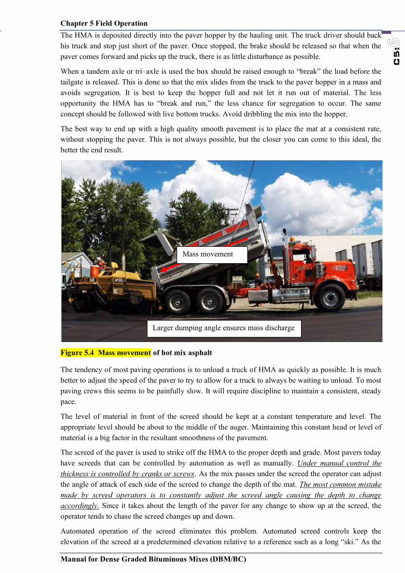
Chapter 5 Field Operation
Manual for Dense Graded Bituminous Mixes (DBM/BC)
C5:
The surface to be sprayed shall be thoroughly cleaned by sweeping with mechanical brooms and/or washing or other approved means. All laitance of soil or binder material, loose and foreign material shall be removed. All loose material shall be swept clear of the layer to expose the full width of the layer upon which tack coat should be applied. The surface to be sprayed should be checked for line, camber and level, and the surface corrected, made good as necessary and approved by the Engineer before any bituminous spray is applied. The Engineer’s approval, or otherwise, of the surface shall be given immediately prior to the Contractor’s intention to start spraying. No traffic shall be allowed on the tacked surface.
Weather conditions can cause a tack coat to break more quickly or more slowly. Generally, the more humid the day, the longer the time the tack will take to break. When paving at night it will generally take longer for the tack coat to break. Excessive tack coat may cause the HMA to slip on the pavement or it could flush through the HMA to the surface.
Figure 5.3 Precaution during Tack Coat Operation
5.6 Hot mix paver operation
Immediately after the surface has been prepared and approved, the mixture should be spread to line and level by the laying plant without segregation and dragging. The mixture should be place in widths of one traffic lane at a time, unless otherwise agreed by the Engineer. The limits on permissible lift thickness should be followed as per Table 2.2. Only on area where irregularities or unavoidable obstacles make the use of mechanical laying impracticable, the mixture may be spread and compacted by hand.
Chapter 5 Field Operation
Manual for Dense Graded Bituminous Mixes (DBM/BC)
C5:
The HMA is deposited directly into the paver hopper by the hauling unit. The truck driver should back his truck and stop just short of the paver. Once stopped, the brake should be released so that when the paver comes forward and picks up the truck, there is as little disturbance as possible.
When a tandem axle or tri–axle is used the box should be raised enough to “break” the load before the tailgate is released. This is done so that the mix slides from the truck to the paver hopper in a mass and avoids segregation. It is best to keep the hopper full and not let it run out of material. The less opportunity the HMA has to “break and run,” the less chance for segregation to occur. The same concept should be followed with live bottom trucks. Avoid dribbling the mix into the hopper.
The best way to end up with a high quality smooth pavement is to place the mat at a consistent rate, without stopping the paver. This is not always possible, but the closer you can come to this ideal, the better the end result.
Figure 5.4 Mass movement of hot mix asphalt
The tendency of most paving operations is to unload a truck of HMA as quickly as possible. It is much better to adjust the speed of the paver to try to allow for a truck to always be waiting to unload. To most paving crews this seems to be painfully slow. It will require discipline to maintain a consistent, steady pace.
The level of material in front of the screed should be kept at a constant temperature and level. The appropriate level should be about to the middle of the auger. Maintaining this constant head or level of material is a big factor in the resultant smoothness of the pavement.
The screed of the paver is used to strike off the HMA to the proper depth and grade. Most pavers today have screeds that can be controlled by automation as well as manually. Under manual control the thickness is controlled by cranks or screws. As the mix passes under the screed the operator can adjust the angle of attack of each side of the screed to change the depth of the mat. The most common mistake made by screed operators is to constantly adjust the screed angle causing the depth to change accordingly. Since it takes about the length of the paver for any change to show up at the screed, the operator tends to chase the screed changes up and down.
Automated operation of the screed eliminates this problem. Automated screed controls keep the elevation of the screed at a predetermined elevation relative to a reference such as a long “ski.” As the
Larger dumping angle ensures mass discharge
Mass movement

Chapter 5 Field Operation
Manual for Dense Graded Bituminous Mixes (DBM/BC)
C5:
ski moves over the existing grade, the deviations in the surface are averaged. The screed is adjusted based on this moving average.
Generally, automated control of the screed will produce a smoother pavement than manual control. However, because the automatic control levels out the pavement over the length of the ski, the thickness will vary. This almost always results in a higher yield than neat line calculation would indicate. If your project is restricted by a predetermined quantity of HMA, it is important to closely monitor the yield.
Segregation
HMA producers and contractors need to be especially vigilant in watching for segregation throughout the whole process of the project. Segregation can happen any time the HMA is moved from one place to another. This includes the manufacture and loading of the material at the plant. At the paving operation, segregation can occur in the paver hopper when the material is dumped into the paver, or at any location in the feed system, and in the augers.
Constant alertness to possible segregation by all members of the paving crew and the owners’ agents can help to overcome segregation problems. Even though material has been successfully processed through the cold feed bin, through the plant, through the surge or storage bin, then uniformly loaded on the truck, segregation can still occur in the paver. Improper operation of a paver can cause segregation in varying degrees. Here are suggestions that should be considered when segregation occurs at the paver.
a. Do not completely empty the hopper between each truck load. Coarse material tends to roll to each side of the truck bed and thus roll directly into the wings of the hopper. By leaving material in the hopper the coarse material has a better chance of being mixed with finer material before being placed on the road.
b. Dump hopper wings only as required to level the material load in the hopper. Dumping eliminates the valleys in the material bed, thereby minimizing rolling that occurs when unloading. It allows the truck tailgate to swing open fully to flood the hopper with mix.
c. Dump the truck so as to flood the hopper. With the hopper as full as possible, material tends to be conveyed out from under the truck and minimizes the tendency to roll as it is dumped into the hopper.
d. Open hopper gates as wide as possible to insure that the augers are full. By closing the gates and starving the augers for mix, fine material will drop directly on the ground causing coarse material to be augered to each side.
e. Run the paver as continuously as possible. Start and stop only as necessary. Adjust the paver speed to balance paver production with plant production.
f. Run augers continuously. Auger speed should be adjusted so that a continuous, slow only of material occurs. Augers that run at high speeds are cycling on and off continuously and contribute signicantly to segregation at the paver.
g. If augers are running too fast, the center of the mat will be decient of material and this will generally result in a coarse strip, Baffle plates, can also prevent coarse materials from rolling in front of the auger gear box and causing center line segregation. With the installation of the baffles, the augers then divert material uniformly to the center.
h. If the outer edges of the paver auger are decient of material, coarse strips along the outsides can occur as the coarse aggregate rolls to the outsides.
i. If possible, adjust paver extensions so that the paver pulls the same amount of material from each side of the hopper. If one side is pulling more material, a valley will form in that side of the paver hopper,

Chapter 5 Field Operation
Manual for Dense Graded Bituminous Mixes (DBM/BC)
C5:
ski moves over the existing grade, the deviations in the surface are averaged. The screed is adjusted based on this moving average.
Generally, automated control of the screed will produce a smoother pavement than manual control. However, because the automatic control levels out the pavement over the length of the ski, the thickness will vary. This almost always results in a higher yield than neat line calculation would indicate. If your project is restricted by a predetermined quantity of HMA, it is important to closely monitor the yield.
Segregation
HMA producers and contractors need to be especially vigilant in watching for segregation throughout the whole process of the project. Segregation can happen any time the HMA is moved from one place to another. This includes the manufacture and loading of the material at the plant. At the paving operation, segregation can occur in the paver hopper when the material is dumped into the paver, or at any location in the feed system, and in the augers.
Constant alertness to possible segregation by all members of the paving crew and the owners’ agents can help to overcome segregation problems. Even though material has been successfully processed through the cold feed bin, through the plant, through the surge or storage bin, then uniformly loaded on the truck, segregation can still occur in the paver. Improper operation of a paver can cause segregation in varying degrees. Here are suggestions that should be considered when segregation occurs at the paver.
a. Do not completely empty the hopper between each truck load. Coarse material tends to roll to each side of the truck bed and thus roll directly into the wings of the hopper. By leaving material in the hopper the coarse material has a better chance of being mixed with finer material before being placed on the road.
b. Dump hopper wings only as required to level the material load in the hopper. Dumping eliminates the valleys in the material bed, thereby minimizing rolling that occurs when unloading. It allows the truck tailgate to swing open fully to flood the hopper with mix.
c. Dump the truck so as to flood the hopper. With the hopper as full as possible, material tends to be conveyed out from under the truck and minimizes the tendency to roll as it is dumped into the hopper.
d. Open hopper gates as wide as possible to insure that the augers are full. By closing the gates and starving the augers for mix, fine material will drop directly on the ground causing coarse material to be augered to each side.
e. Run the paver as continuously as possible. Start and stop only as necessary. Adjust the paver speed to balance paver production with plant production.
f. Run augers continuously. Auger speed should be adjusted so that a continuous, slow only of material occurs. Augers that run at high speeds are cycling on and off continuously and contribute signicantly to segregation at the paver.
g. If augers are running too fast, the center of the mat will be decient of material and this will generally result in a coarse strip, Baffle plates, can also prevent coarse materials from rolling in front of the auger gear box and causing center line segregation. With the installation of the baffles, the augers then divert material uniformly to the center.
h. If the outer edges of the paver auger are decient of material, coarse strips along the outsides can occur as the coarse aggregate rolls to the outsides.
i. If possible, adjust paver extensions so that the paver pulls the same amount of material from each side of the hopper. If one side is pulling more material, a valley will form in that side of the paver hopper,
Chapter 5 Field Operation
Manual for Dense Graded Bituminous Mixes (DBM/BC)
C5:
causing segregation to occur in sensitive mixes. If correction cannot be made by adjusting the extension, offset the truck slightly towards the side requiring more material to even out the material bed in the hopper.
j. Pavers without auger extensions can cause outside edge segregation. A segregation prone mix can segregate without auger extensions as the mix piles up at the end of the auger and the larger aggregate rolls off toward the outside edge of the road.
5.7 Hot mix compaction
Without a doubt, compaction is the most critical element in the durability of the HMA pavement. The amount of material passing the 74 µm (#200) sieve can have a dramatic effect on the compaction of a mix. A higher percentage of minus 74 µm (#200) material will generally make a mix more difficult to compact.
Immediately after the bituminous mixture has been spread, it should be thoroughly and uniformly compacted by rolling. The layer should be rolled when the mixture is in such a condition that rolling does not cause undue displacement or shoving.
The number, weight and type of rollers furnished should be sufficient to obtain required compaction while the mixture is in a workable condition. Initial rolling with a steel tandem of three-wheeled roller should follow the laying plant as closely as possible. The rollers should be operated with the drive roll nearest the laying plant, at a slow and uniform speed (not exceeding 5 km/h).
Figure 5.5 Recommended rolling pattern
Intermediate rolling with a pneumatic tyre or vibratory roller should follow immediately. Final rolling with a steel wheeled roller should be used to eliminate marks from previous rolling. To prevent adhesion of the mixture to the rollers, the wheels should be kept lightly moistened with water. In areas too small for the roller, a vibrating rate plate compactor or a hand tamper should be used to achieve the specified compaction. The recommended rolling pattern is as per figure 5.5. Every pass of the roller should proceed straight into the compacted mix and return in the same path. After the required passes are completed, the roller should move to the outside of the pavement on cooled material and repeat the procedure.
Basis rules for rolling:
o Decelerate and accelerate slowly and smoothly whenever switching direction. This is to avoid shoving the mat.
o Shut off vibration when slowing the roller to a stop, and start it again when the roller is moving over 0.8 km/hr.
o For vibratory rollers, make sure to operate at a speed that will achieve at least 10 impacts per 300 mm (one foot) of travel.

Chapter 5 Field Operation
Manual for Dense Graded Bituminous Mixes (DBM/BC)
C5:
o When ending a pass of the roller, turn the roller into a slight curve before stopping. This is to avoid leaving a transverse ridge in the HMA mat.
o Avoid sharp turns that will shove and cut the mat. o Whenever you stop the roller, park at an angle on a cool part of the mat to avoid leaving an
indentation.
The lead roller should stay as close as possible to the paver to achieve as much density as possible while the mat is still hot.
Rolling should begin from the lowest edge. This lower edge will become a support for subsequent passes. Rolling lanes should be changed by making the turns on the compacted areas. All turns should be gentle to decrease the risk of cracking the mat. On a super elevated turn, start rolling at the low side edge and work toward the super elevated edge. Overlap rolling passes by 100 to 150 mm. It may be necessary to stay about 300 mm away from the unconfined edge of a lane on the first pass to prevent the material from shoving out. On the subsequent pass, the roller can roll the 300mm of uncompacted material.
5.8 Joints
Any mixture that becomes loose and broken, mixed with dirt or foreign matter or is in any way defective, should be replaced with fresh hot mixture, which should be compacted to conform to the surrounding area.
Spreading of the mixture should be as continuous as possible. Any fresh mixture spread accidentally on the existing work at a joint shall be carefully removed by brooming it back on to un-compacted work, so as to avoid formation of irregularities at the joint. The finish at joints shall comply with the surface requirements and shall present the same uniformity of finish, texture and density as other sections of the work.
Transverse joints shall be formed by cutting neatly in a straight line across the previous run to expose the full depth of the course. Longitudinal joints should be rolled directly behind the paving operation.
Many pavements prematurely fail. Most often this is due to segregation of the mix at the joint and improper compaction. To produce a good paving joint, the material needs to be as close to the same consistency as possible, not segregated, and compacted to as close to the same density as the mat itself.
There are two types of joints: Traditional “butt” joint
The objective here is to produce as close to a vertical edge as possible as the material is placed with the paver for the unconfined edges. The key to this is to maintain a consistent head of material in front of the screed to prevent segregation. The end gate of the paver must be secure and extended to the back of the screed. The end gate must be adjusted to ride on the existing pavement and create as vertical an edge as possible.
Figure 5.6 Traditional “butt” joint “Wedge” joint
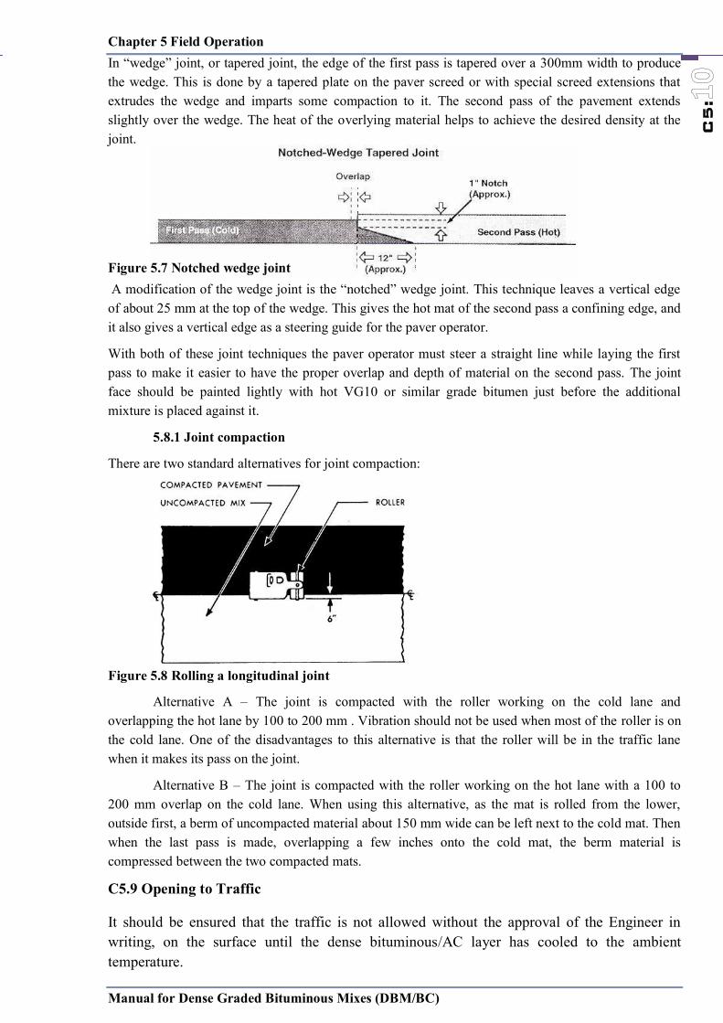
Chapter 5 Field Operation
Manual for Dense Graded Bituminous Mixes (DBM/BC)
C5:
o When ending a pass of the roller, turn the roller into a slight curve before stopping. This is to avoid leaving a transverse ridge in the HMA mat.
o Avoid sharp turns that will shove and cut the mat. o Whenever you stop the roller, park at an angle on a cool part of the mat to avoid leaving an
indentation.
The lead roller should stay as close as possible to the paver to achieve as much density as possible while the mat is still hot.
Rolling should begin from the lowest edge. This lower edge will become a support for subsequent passes. Rolling lanes should be changed by making the turns on the compacted areas. All turns should be gentle to decrease the risk of cracking the mat. On a super elevated turn, start rolling at the low side edge and work toward the super elevated edge. Overlap rolling passes by 100 to 150 mm. It may be necessary to stay about 300 mm away from the unconfined edge of a lane on the first pass to prevent the material from shoving out. On the subsequent pass, the roller can roll the 300mm of uncompacted material.
5.8 Joints
Any mixture that becomes loose and broken, mixed with dirt or foreign matter or is in any way defective, should be replaced with fresh hot mixture, which should be compacted to conform to the surrounding area.
Spreading of the mixture should be as continuous as possible. Any fresh mixture spread accidentally on the existing work at a joint shall be carefully removed by brooming it back on to un-compacted work, so as to avoid formation of irregularities at the joint. The finish at joints shall comply with the surface requirements and shall present the same uniformity of finish, texture and density as other sections of the work.
Transverse joints shall be formed by cutting neatly in a straight line across the previous run to expose the full depth of the course. Longitudinal joints should be rolled directly behind the paving operation.
Many pavements prematurely fail. Most often this is due to segregation of the mix at the joint and improper compaction. To produce a good paving joint, the material needs to be as close to the same consistency as possible, not segregated, and compacted to as close to the same density as the mat itself.
There are two types of joints: Traditional “butt” joint
The objective here is to produce as close to a vertical edge as possible as the material is placed with the paver for the unconfined edges. The key to this is to maintain a consistent head of material in front of the screed to prevent segregation. The end gate of the paver must be secure and extended to the back of the screed. The end gate must be adjusted to ride on the existing pavement and create as vertical an edge as possible.
Figure 5.6 Traditional “butt” joint “Wedge” joint
Chapter 5 Field Operation
Manual for Dense Graded Bituminous Mixes (DBM/BC)
C5:
In “wedge” joint, or tapered joint, the edge of the first pass is tapered over a 300mm width to produce the wedge. This is done by a tapered plate on the paver screed or with special screed extensions that extrudes the wedge and imparts some compaction to it. The second pass of the pavement extends slightly over the wedge. The heat of the overlying material helps to achieve the desired density at the joint. Figure 5.7 Notched wedge joint A modification of the wedge joint is the “notched” wedge joint. This technique leaves a vertical edge of about 25 mm at the top of the wedge. This gives the hot mat of the second pass a confining edge, and it also gives a vertical edge as a steering guide for the paver operator.
With both of these joint techniques the paver operator must steer a straight line while laying the first pass to make it easier to have the proper overlap and depth of material on the second pass. The joint face should be painted lightly with hot VG10 or similar grade bitumen just before the additional mixture is placed against it.
5.8.1 Joint compaction
There are two standard alternatives for joint compaction:
Figure 5.8 Rolling a longitudinal joint
Alternative A – The joint is compacted with the roller working on the cold lane and overlapping the hot lane by 100 to 200 mm . Vibration should not be used when most of the roller is on the cold lane. One of the disadvantages to this alternative is that the roller will be in the traffic lane when it makes its pass on the joint.
Alternative B – The joint is compacted with the roller working on the hot lane with a 100 to 200 mm overlap on the cold lane. When using this alternative, as the mat is rolled from the lower, outside first, a berm of uncompacted material about 150 mm wide can be left next to the cold mat. Then when the last pass is made, overlapping a few inches onto the cold mat, the berm material is compressed between the two compacted mats.
C5.9 Opening to Traffic
It should be ensured that the traffic is not allowed without the approval of the Engineer in writing, on the surface until the dense bituminous/AC layer has cooled to the ambient temperature.
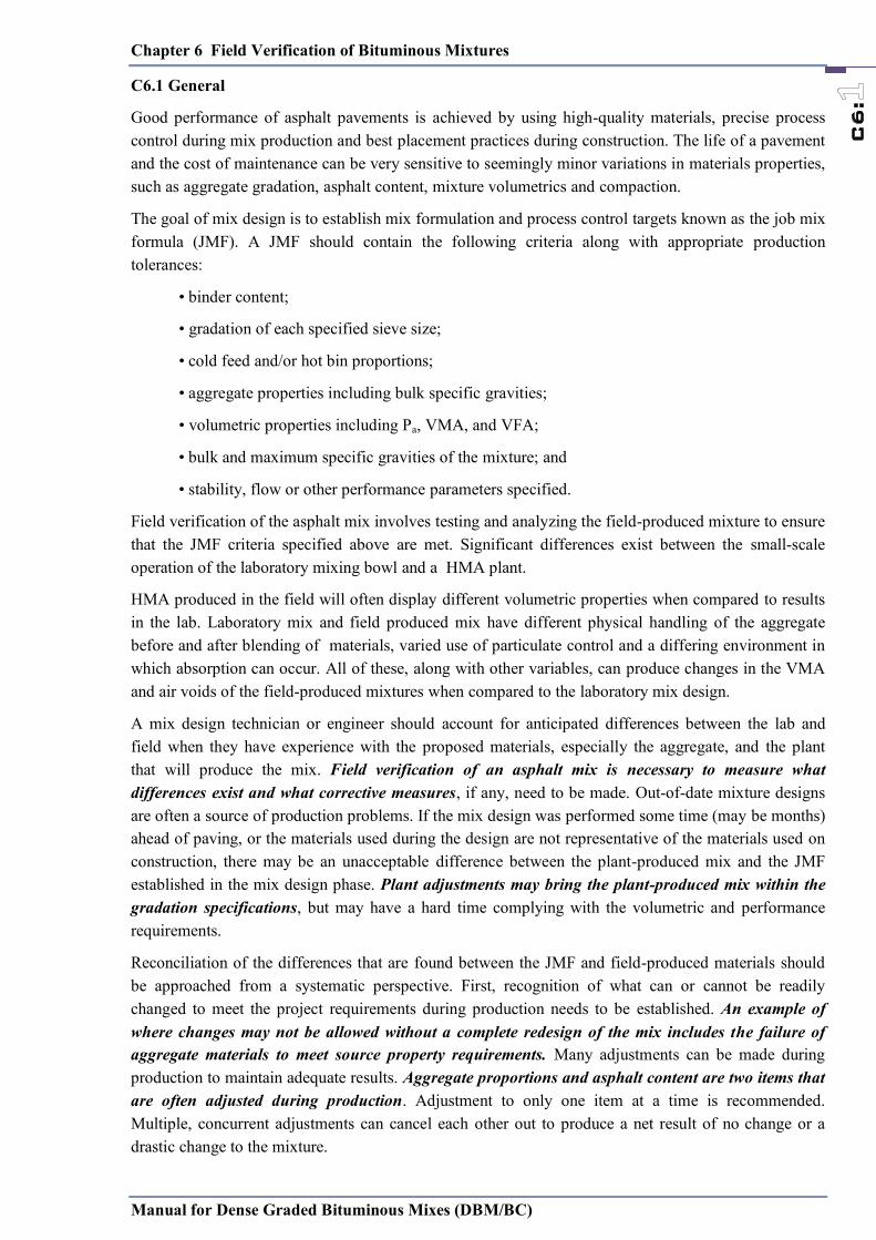
Chapter 6 Field Verification of Bituminous Mixtures
Manual for Dense Graded Bituminous Mixes (DBM/BC)
C6:
C6.1 General
Good performance of asphalt pavements is achieved by using high-quality materials, precise process control during mix production and best placement practices during construction. The life of a pavement and the cost of maintenance can be very sensitive to seemingly minor variations in materials properties, such as aggregate gradation, asphalt content, mixture volumetrics and compaction.
The goal of mix design is to establish mix formulation and process control targets known as the job mix formula (JMF). A JMF should contain the following criteria along with appropriate production tolerances:
• binder content;
• gradation of each specified sieve size;
• cold feed and/or hot bin proportions;
• aggregate properties including bulk specific gravities;
• volumetric properties including Pa, VMA, and VFA;
• bulk and maximum specific gravities of the mixture; and
• stability, flow or other performance parameters specified.
Field verification of the asphalt mix involves testing and analyzing the field-produced mixture to ensure that the JMF criteria specified above are met. Significant differences exist between the small-scale operation of the laboratory mixing bowl and a HMA plant.
HMA produced in the field will often display different volumetric properties when compared to results in the lab. Laboratory mix and field produced mix have different physical handling of the aggregate before and after blending of materials, varied use of particulate control and a differing environment in which absorption can occur. All of these, along with other variables, can produce changes in the VMA and air voids of the field-produced mixtures when compared to the laboratory mix design.
A mix design technician or engineer should account for anticipated differences between the lab and field when they have experience with the proposed materials, especially the aggregate, and the plant that will produce the mix. Field verification of an asphalt mix is necessary to measure what differences exist and what corrective measures, if any, need to be made. Out-of-date mixture designs are often a source of production problems. If the mix design was performed some time (may be months) ahead of paving, or the materials used during the design are not representative of the materials used on construction, there may be an unacceptable difference between the plant-produced mix and the JMF established in the mix design phase. Plant adjustments may bring the plant-produced mix within the gradation specifications, but may have a hard time complying with the volumetric and performance requirements.
Reconciliation of the differences that are found between the JMF and field-produced materials should be approached from a systematic perspective. First, recognition of what can or cannot be readily changed to meet the project requirements during production needs to be established. An example of where changes may not be allowed without a complete redesign of the mix includes the failure of aggregate materials to meet source property requirements. Many adjustments can be made during production to maintain adequate results. Aggregate proportions and asphalt content are two items that are often adjusted during production. Adjustment to only one item at a time is recommended. Multiple, concurrent adjustments can cancel each other out to produce a net result of no change or a drastic change to the mixture.
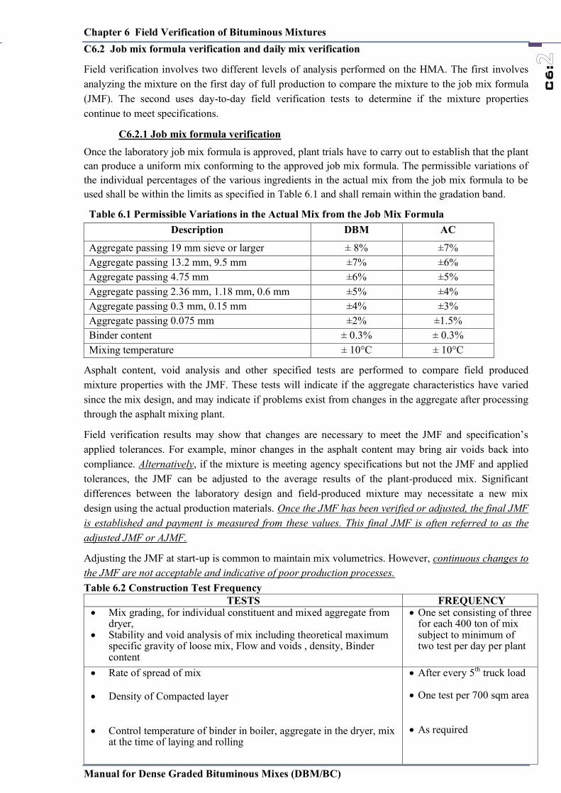
Chapter 6 Field Verification of Bituminous Mixtures
Manual for Dense Graded Bituminous Mixes (DBM/BC)
C6:
C6.2 Job mix formula verification and daily mix verification
Field verification involves two different levels of analysis performed on the HMA. The first involves analyzing the mixture on the first day of full production to compare the mixture to the job mix formula (JMF). The second uses day-to-day field verification tests to determine if the mixture properties continue to meet specifications.
C6.2.1 Job mix formula verification Once the laboratory job mix formula is approved, plant trials have to carry out to establish that the plant can produce a uniform mix conforming to the approved job mix formula. The permissible variations of the individual percentages of the various ingredients in the actual mix from the job mix formula to be used shall be within the limits as specified in Table 6.1 and shall remain within the gradation band.
Table 6.1 Permissible Variations in the Actual Mix from the Job Mix Formula Description DBM AC
Aggregate passing 19 mm sieve or larger ± 8% ±7% Aggregate passing 13.2 mm, 9.5 mm ±7% ±6% Aggregate passing 4.75 mm ±6% ±5% Aggregate passing 2.36 mm, 1.18 mm, 0.6 mm ±5% ±4% Aggregate passing 0.3 mm, 0.15 mm ±4% ±3% Aggregate passing 0.075 mm ±2% ±1.5% Binder content ± 0.3% ± 0.3% Mixing temperature ± 10°C ± 10°C
Asphalt content, void analysis and other specified tests are performed to compare field produced mixture properties with the JMF. These tests will indicate if the aggregate characteristics have varied since the mix design, and may indicate if problems exist from changes in the aggregate after processing through the asphalt mixing plant.
Field verification results may show that changes are necessary to meet the JMF and specification’s applied tolerances. For example, minor changes in the asphalt content may bring air voids back into compliance. Alternatively, if the mixture is meeting agency specifications but not the JMF and applied tolerances, the JMF can be adjusted to the average results of the plant-produced mix. Significant differences between the laboratory design and field-produced mixture may necessitate a new mix design using the actual production materials. Once the JMF has been verified or adjusted, the final JMF is established and payment is measured from these values. This final JMF is often referred to as the adjusted JMF or AJMF.
Adjusting the JMF at start-up is common to maintain mix volumetrics. However, continuous changes to the JMF are not acceptable and indicative of poor production processes. Table 6.2 Construction Test Frequency
TESTS FREQUENCY Mix grading, for individual constituent and mixed aggregate from
dryer, Stability and void analysis of mix including theoretical maximum
specific gravity of loose mix, Flow and voids , density, Binder content
One set consisting of three for each 400 ton of mix subject to minimum of two test per day per plant
Rate of spread of mix
Density of Compacted layer
Control temperature of binder in boiler, aggregate in the dryer, mix
at the time of laying and rolling
After every 5th truck load
One test per 700 sqm area
As required

Chapter 6 Field Verification of Bituminous Mixtures
Manual for Dense Graded Bituminous Mixes (DBM/BC)
C6:
C6.2.2. Daily mix verification
Daily testing can provide an early warning by indicating if the mixture properties deviate from the specifications. This daily verification is part of plant process control that can identify potential acceptance problems before a large amount of mix is placed.
Daily field verification tests are typically performed on random samples taken from a set quantity of material called a lot. A lot is typically a day’s production or a 400 tonnage of material.
Roadway Sampling Random sampling locations should be determined. Sample the uncompacted mat by placing a template through the entire lift of HMA, or using a square pointed shovel to create a sample area with vertical faces. Remove all material from within the template or between the vertical faces and place in a clean sample container. Avoid contaminating the sample with any underlying material. At least three increments should be obtained for each sample.
Figure 6.1 Template Placed in Asphalt Mat Cleaning Asphalt Off Template into Sample Container
Truck Sampling When roadway sampling is not practical, then truck sampling should be used.Sample from the truckload by first removing approximately one foot of material from the outside of the mass. Using a square shovel or scoop, remove enough material from the sample area to provide approximately one-third of the sample size. Care must be taken to avoid segregating the material while sampling. Place each increment in the clean sample container. At least three increments should be obtained for each sample. Increments from more than one truckload should be included in the sample. Figure 6.2 Sampling from a Truck Scraping Sample Off Shovel into Sample Box
Sample Identification Properly identify each sample by marking the sample container with a project identifier, the type of material, date, time, and the sample location. This is the minimum information that should be included with each sample.
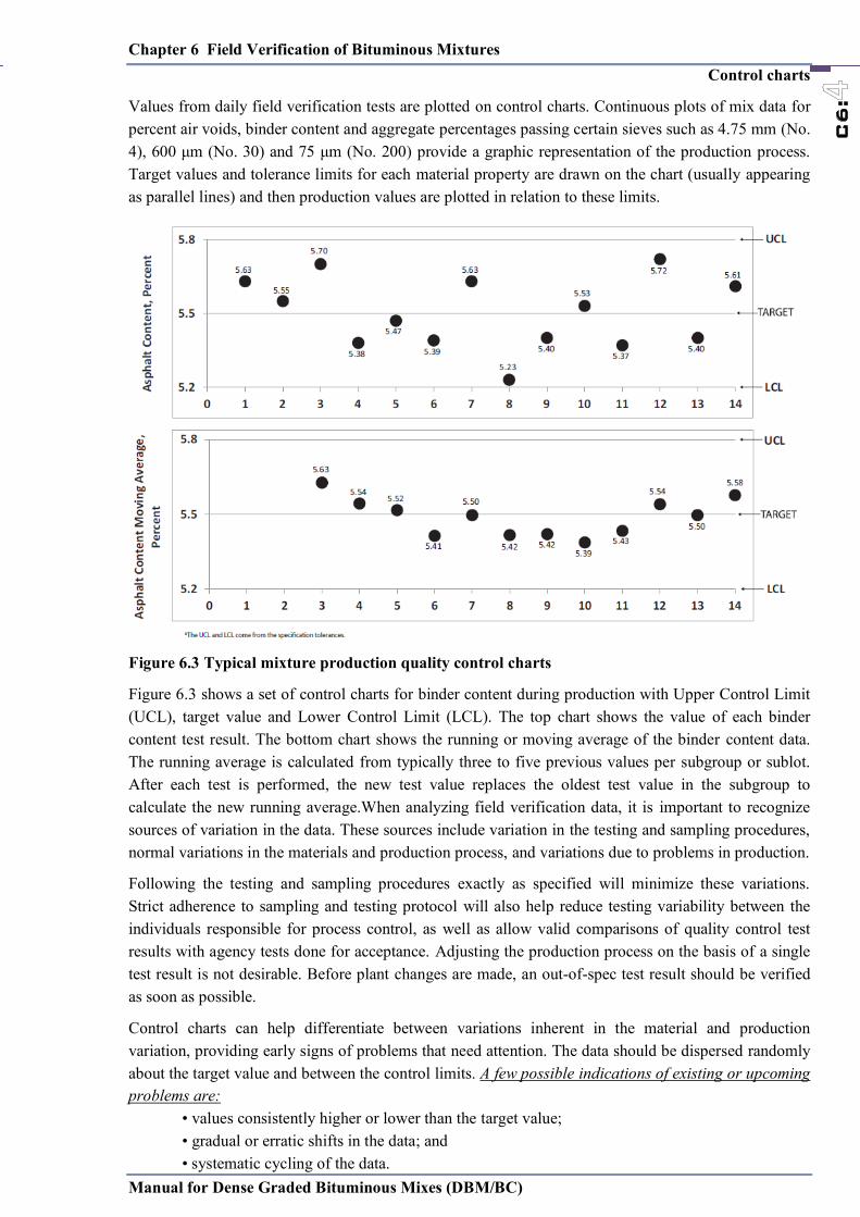
Chapter 6 Field Verification of Bituminous Mixtures
Manual for Dense Graded Bituminous Mixes (DBM/BC)
C6:
Control charts
Values from daily field verification tests are plotted on control charts. Continuous plots of mix data for percent air voids, binder content and aggregate percentages passing certain sieves such as 4.75 mm (No. 4), 600 μm (No. 30) and 75 μm (No. 200) provide a graphic representation of the production process. Target values and tolerance limits for each material property are drawn on the chart (usually appearing as parallel lines) and then production values are plotted in relation to these limits.
Figure 6.3 Typical mixture production quality control charts
Figure 6.3 shows a set of control charts for binder content during production with Upper Control Limit (UCL), target value and Lower Control Limit (LCL). The top chart shows the value of each binder content test result. The bottom chart shows the running or moving average of the binder content data. The running average is calculated from typically three to five previous values per subgroup or sublot. After each test is performed, the new test value replaces the oldest test value in the subgroup to calculate the new running average.When analyzing field verification data, it is important to recognize sources of variation in the data. These sources include variation in the testing and sampling procedures, normal variations in the materials and production process, and variations due to problems in production.
Following the testing and sampling procedures exactly as specified will minimize these variations. Strict adherence to sampling and testing protocol will also help reduce testing variability between the individuals responsible for process control, as well as allow valid comparisons of quality control test results with agency tests done for acceptance. Adjusting the production process on the basis of a single test result is not desirable. Before plant changes are made, an out-of-spec test result should be verified as soon as possible.
Control charts can help differentiate between variations inherent in the material and production variation, providing early signs of problems that need attention. The data should be dispersed randomly about the target value and between the control limits. A few possible indications of existing or upcoming problems are:
• values consistently higher or lower than the target value; • gradual or erratic shifts in the data; and • systematic cycling of the data.
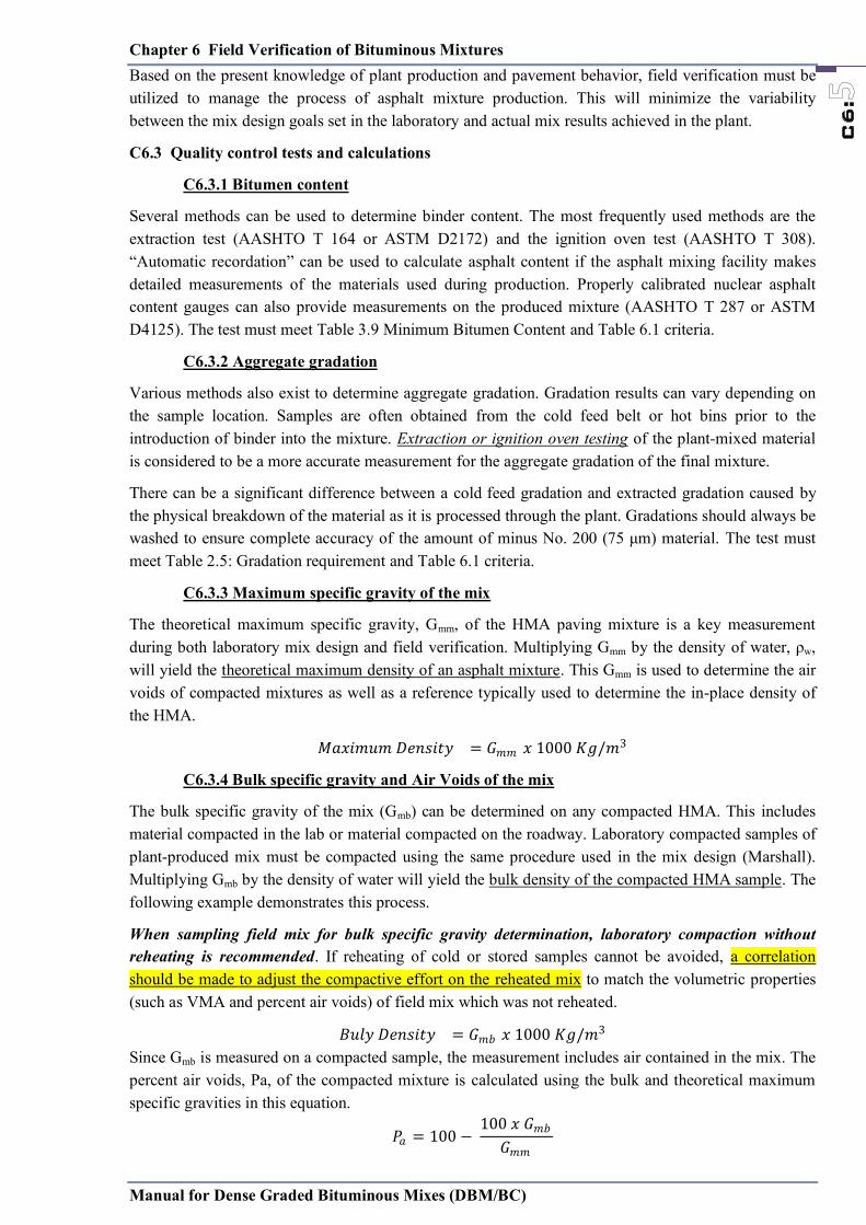
Chapter 6 Field Verification of Bituminous Mixtures
Manual for Dense Graded Bituminous Mixes (DBM/BC)
C6:
Based on the present knowledge of plant production and pavement behavior, field verification must be utilized to manage the process of asphalt mixture production. This will minimize the variability between the mix design goals set in the laboratory and actual mix results achieved in the plant.
C6.3 Quality control tests and calculations
C6.3.1 Bitumen content
Several methods can be used to determine binder content. The most frequently used methods are the extraction test (AASHTO T 164 or ASTM D2172) and the ignition oven test (AASHTO T 308). ―Automatic recordation‖ can be used to calculate asphalt content if the asphalt mixing facility makes detailed measurements of the materials used during production. Properly calibrated nuclear asphalt content gauges can also provide measurements on the produced mixture (AASHTO T 287 or ASTM D4125). The test must meet Table 3.9 Minimum Bitumen Content and Table 6.1 criteria.
C6.3.2 Aggregate gradation
Various methods also exist to determine aggregate gradation. Gradation results can vary depending on the sample location. Samples are often obtained from the cold feed belt or hot bins prior to the introduction of binder into the mixture. Extraction or ignition oven testing of the plant-mixed material is considered to be a more accurate measurement for the aggregate gradation of the final mixture.
There can be a significant difference between a cold feed gradation and extracted gradation caused by the physical breakdown of the material as it is processed through the plant. Gradations should always be washed to ensure complete accuracy of the amount of minus No. 200 (75 μm) material. The test must meet Table 2.5: Gradation requirement and Table 6.1 criteria.
C6.3.3 Maximum specific gravity of the mix
The theoretical maximum specific gravity, Gmm, of the HMA paving mixture is a key measurement during both laboratory mix design and field verification. Multiplying Gmm by the density of water, ρw, will yield the theoretical maximum density of an asphalt mixture. This Gmm is used to determine the air voids of compacted mixtures as well as a reference typically used to determine the in-place density of the HMA.
𝑀𝑀𝑎𝑎𝑥𝑥𝑖𝑖𝑚𝑚𝑢𝑢𝑚𝑚 𝐷𝐷𝑒𝑒𝑛𝑛𝑠𝑠𝑖𝑖𝑡𝑡𝑦𝑦 𝐺𝐺𝑚𝑚𝑚𝑚 𝑥𝑥 𝐾𝐾𝑔𝑔 𝑚𝑚
C6.3.4 Bulk specific gravity and Air Voids of the mix
The bulk specific gravity of the mix (Gmb) can be determined on any compacted HMA. This includes material compacted in the lab or material compacted on the roadway. Laboratory compacted samples of plant-produced mix must be compacted using the same procedure used in the mix design (Marshall). Multiplying Gmb by the density of water will yield the bulk density of the compacted HMA sample. The following example demonstrates this process.
When sampling field mix for bulk specific gravity determination, laboratory compaction without reheating is recommended. If reheating of cold or stored samples cannot be avoided, a correlation should be made to adjust the compactive effort on the reheated mix to match the volumetric properties (such as VMA and percent air voids) of field mix which was not reheated.
𝐵𝐵𝑢𝑢𝑙𝑙𝑦𝑦 𝐷𝐷𝑒𝑒𝑛𝑛𝑠𝑠𝑖𝑖𝑡𝑡𝑦𝑦 𝐺𝐺𝑚𝑚𝑏𝑏 𝑥𝑥 𝐾𝐾𝑔𝑔 𝑚𝑚 Since Gmb is measured on a compacted sample, the measurement includes air contained in the mix. The percent air voids, Pa, of the compacted mixture is calculated using the bulk and theoretical maximum specific gravities in this equation.
𝑃𝑃𝑎𝑎 − 𝑥𝑥 𝐺𝐺𝑚𝑚𝑏𝑏𝐺𝐺𝑚𝑚𝑚𝑚
Chapter 6 Field Verification of Bituminous Mixtures
Manual for Dense Graded Bituminous Mixes (DBM/BC)
C6:
C6.3.5 Stability (Marshall) and flow (Marshall)
These properties can be measured on the laboratory compacted samples of field-produced material. These tests have traditionally been utilized as a measure to indicate the rutting resistance and durability of an HMA. However, these values are affected by many different aggregate and asphalt properties and are less reliable than volumetric property tests for predicting pavement performance. If the volumetric properties (air voids, VMA, asphalt content) and the aggregate quality and gradation of the mixture are properly controlled, then the stability and flow will normally meet the appropriate specifications. The field specimen should comply the Table 3.8 Marshall Mix Design Criteria.
C6.4 Volumetric adjustments
The most common problem encountered in plant produced mix is the failure to meet VMA and air voids volumetric parameters. These properties are related in that a failing air voids test is usually the result of a changing VMA—assuming the binder content is correct. The change in VMA is most often explained by inconsistent mixture curing during testing or a change in the gradation of the aggregate. Mixture conditioning of samples is essential in providing accurate volumetric properties. Changes in air voids or VMA are often encountered and go unexplained. Careful observation of material conditioning times can often explain fluctuating volumetric test results. The time and temperature of mixture conditioning can greatly affect the amount of asphalt absorbed in the aggregate, thus changing the theoretical maximum specific gravity (Gmm) and, to a lesser extent, bulk specific gravity (Gmb) test results. For example, Gmm samples taken from a truck at the plant and allowed to immediately cool can have significantly lower results (lowered absorbed asphalt) than if the same material were hauled to the roadway, sampled behind the paver, and returned to the plant lab in an insulated specimen container, and then allowed to cool. It is common for neither of these scenarios to match the curing time performed in the laboratory during the mix design process. In order for field-produced mixtures to match laboratory design values, mix samples should be cured at similar temperatures for a similar length of time. Highly absorptive matching the curing time and temperature in the lab to that in the field.
It is important to remember that VMA measured on a lab-compacted specimen is the result of the amount of aggregate packing that occurs in the mold when placed in the compactor. Anything that changes the amount of aggregate that can be compacted into the specimen will affect the resulting VMA. A change on one aggregate sieve can alter the compaction characteristics of the mix and change the way the entire aggregate structure ―fits‖ together. A common scenario when going from design in the lab to production in the field is that the aggregate experiences further ―breakdown‖ in the plant relative to the mixing bowl. This breakdown can create a higher percentage of minus No. 200 material (dust) that will decrease air voids and decrease (collapse) VMA in a compacted sample. The following is a non-inclusive list of techniques that may be tried to increase VMA:
1. movement away from the maximum density line, 2. use of highly angular particles, 3. use of particles with a rough surface texture, 4. use of different shaped particles, 5. use of different composition of materials, i.e., siliceous vs. calcareous, and 6. reduction in the amount of P0.075 used in the mix.
When QC/QA plans only require the monitoring of the air voids in a mixture, and when VMA unknowingly decreases, it is a common adjustment to simply reduce the amount of binder being added to the mixture to restore the specified air voids level. Caution should be exercised here as the real reason for the lower air voids is the collapse of the available VMA in the mix or the binder coating the

Chapter 6 Field Verification of Bituminous Mixtures
Manual for Dense Graded Bituminous Mixes (DBM/BC)
C6:
aggregate has not had sufficient time to be absorbed. Simply reducing the binder content may correct the air voids deviation but leave the mixture with an insufficient amount of binder to provide a durable, fatigue-resistant pavement. Other options exist to restore the VMA in a mixture, including but not limited to the following suggestions:
• Evaluate sampling and testing procedures to assure a standardization of curing parameters;
• Make gradation changes that generate additional VMA;
• Increase the fracture content of the aggregate;
• Reduce natural sand components and increase the usage of manufactured sand;
• Introduce highly fractured, durable, intermediate-sized ―chips‖ into the aggregate structure;
• Reduce the dust in the mixture by increasing the fine aggregates that contain less material passing the No. 200 sieve, or by not returning all of the material from the dust collection system; and
• Wash the aggregates to reduce the dust.
Powerful, advanced techniques exist today that can be highly useful in guiding plant operators to the most efficient adjustment for their situation. Perhaps the most widely recognized and refined of these is the Bailey Method. With tools like the Bailey Method, mathematical predictions of how a proposed gradation change will affect VMA, and thus other volumetric properties, can be made.
A quality control manager can investigate various scenarios, typically via a spreadsheet, to determine which bin adjustments will likely best reconcile their mix to the correct volumetric properties. The Bailey Method explains why very small changes in gradation can have a dramatic effect on the resulting volumetric properties depending on the mixture. More information on the Bailey Method can be found on the Asphalt Institute’s website.
Absent of Bailey Method-like tools, trial-and error plant adjustments based on experience can be made to achieve compliance with the JMF. The complex dynamics of a mix does not allow for this manual to fully address the unique circumstances of individual situations. It must be emphasized that regardless of mixture adjustment techniques utilized, uniformity of stockpiled materials are essential in producing quality asphalt mix. It is very difficult, if not impossible, to predict the results of a change in bin proportions when dealing with highly variable stockpiles
C6.5 Density specifications
The goal of compaction is to achieve a smooth, uniform surface at optimum air voids content that ultimately determines whether the pavement will perform as expected. The in-place air voids of HMA after compaction is a very important factor that affects performance of the mixture throughout the life of the pavement. Achieving compliance with compaction specifications is the final step in the quality management of the HMA construction procedures and must be accomplished to produce a quality asphalt pavement.
The Engineer can direct additional testing as required to fulfil the requirement as specified in specification. The acceptance criteria for tests on density shall subject to the condition that the mean value is not less than the specified value plus:
− 𝑁𝑁𝑜𝑜 𝑜𝑜𝑓𝑓 𝑠𝑠𝑎𝑎𝑚𝑚𝑝𝑝𝑙𝑙𝑒𝑒𝑠𝑠
𝑥𝑥 𝑠𝑠𝑡𝑡𝑎𝑎𝑛𝑛𝑑𝑑𝑎𝑎𝑟𝑟𝑑𝑑 𝑑𝑑𝑒𝑒𝑣𝑣𝑖𝑖𝑎𝑎𝑡𝑡𝑖𝑖𝑜𝑜𝑛𝑛
If the results of any tests show that any of the constituent materials fail to comply with this Specification, the Contractor should carry out whatever changes may be necessary to the materials and/or to the source of supply to ensure compliance.
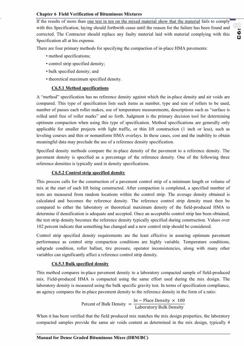
Chapter 6 Field Verification of Bituminous Mixtures
Manual for Dense Graded Bituminous Mixes (DBM/BC)
C6:
If the results of more than one test in ten on the mixed material show that the material fails to comply with this Specification, laying should forthwith cease until the reason for the failure has been found and corrected. The Contractor should replace any faulty material laid with material complying with this Specification all at his expense.
There are four primary methods for specifying the compaction of in-place HMA pavements:
• method specifications;
• control strip specified density;
• bulk specified density; and
• theoretical maximum specified density.
C6.5.1 Method specifications
A ―method‖ specification has no reference density against which the in-place density and air voids are compared. This type of specification lists such items as number, type and size of rollers to be used, number of passes each roller makes, use of temperature measurements, descriptions such as ―surface is rolled until free of roller marks‖ and so forth. Judgment is the primary decision tool for determining optimum compaction when using this type of specification. Method specifications are generally only applicable for smaller projects with light traffic, or thin lift construction (1 inch or less), such as leveling courses and thin or nonuniform HMA overlays. In these cases, cost and the inability to obtain meaningful data may preclude the use of a reference density specification.
Specified density methods compare the in-place density of the pavement to a reference density. The pavement density is specified as a percentage of the reference density. One of the following three reference densities is typically used in density specifications.
C6.5.2 Control strip specified density
This process calls for the construction of a pavement control strip of a minimum length or volume of mix at the start of each lift being constructed. After compaction is completed, a specified number of tests are measured from random locations within the control strip. The average density obtained is calculated and becomes the reference density. The reference control strip density must then be compared to either the laboratory or theoretical maximum density of the field-produced HMA to determine if densification is adequate and accepted. Once an acceptable control strip has been obtained, the test strip density becomes the reference density typically specified during construction. Values over 102 percent indicate that something has changed and a new control strip should be considered.
Control strip specified density requirements are the least effective in assuring optimum pavement performance as control strip compaction conditions are highly variable. Temperature conditions, subgrade condition, roller ballast, tire pressure, operator inconsistencies, along with many other variables can significantly affect a reference control strip density.
C6.5.3 Bulk specified density
This method compares in-place pavement density to a laboratory compacted sample of field-produced mix. Field-produced HMA is compacted using the same effort used during the mix design. The laboratory density is measured using the bulk specific gravity test. In terms of specification compliance, an agency compares the in-place pavement density to the reference density in the form of a ratio:
Percent of Bulk Density −
When it has been verified that the field produced mix matches the mix design properties, the laboratory compacted samples provide the same air voids content as determined in the mix design, typically 4
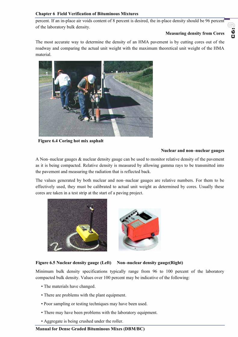
Chapter 6 Field Verification of Bituminous Mixtures
Manual for Dense Graded Bituminous Mixes (DBM/BC)
C6:
percent. If an in-place air voids content of 8 percent is desired, the in-place density should be 96 percent of the laboratory bulk density.
Measuring density from Cores
The most accurate way to determine the density of an HMA pavement is by cutting cores out of the roadway and comparing the actual unit weight with the maximum theoretical unit weight of the HMA material.
Nuclear and non–nuclear gauges
A Non–nuclear gauges & nuclear density gauge can be used to monitor relative density of the pavement as it is being compacted. Relative density is measured by allowing gamma rays to be transmitted into the pavement and measuring the radiation that is reflected back.
The values generated by both nuclear and non–nuclear gauges are relative numbers. For them to be effectively used, they must be calibrated to actual unit weight as determined by cores. Usually these cores are taken in a test strip at the start of a paving project.
Figure 6.5 Nuclear density gauge (Left) Non–nuclear density gauge(Right)
Minimum bulk density specifications typically range from 96 to 100 percent of the laboratory compacted bulk density. Values over 100 percent may be indicative of the following:
• The materials have changed.
• There are problems with the plant equipment.
• Poor sampling or testing techniques may have been used.
• There may have been problems with the laboratory equipment.
• Aggregate is being crushed under the roller.
Figure 6.4 Coring hot mix asphalt
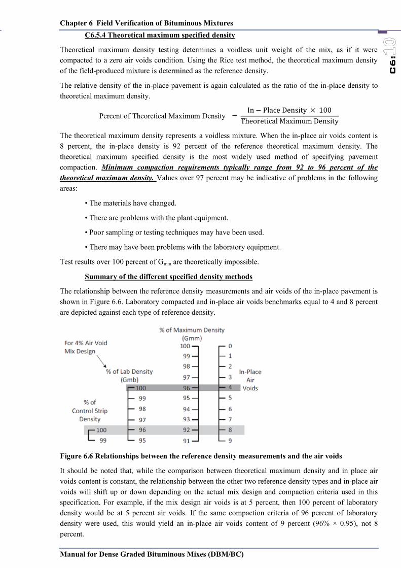
Chapter 6 Field Verification of Bituminous Mixtures
Manual for Dense Graded Bituminous Mixes (DBM/BC)
C6:
C6.5.4 Theoretical maximum specified density
Theoretical maximum density testing determines a voidless unit weight of the mix, as if it were compacted to a zero air voids condition. Using the Rice test method, the theoretical maximum density of the field-produced mixture is determined as the reference density.
The relative density of the in-place pavement is again calculated as the ratio of the in-place density to theoretical maximum density.
Percent of Theoretical Maximum Density −
The theoretical maximum density represents a voidless mixture. When the in-place air voids content is 8 percent, the in-place density is 92 percent of the reference theoretical maximum density. The theoretical maximum specified density is the most widely used method of specifying pavement compaction. Minimum compaction requirements typically range from 92 to 96 percent of the theoretical maximum density. Values over 97 percent may be indicative of problems in the following areas:
• The materials have changed.
• There are problems with the plant equipment.
• Poor sampling or testing techniques may have been used.
• There may have been problems with the laboratory equipment.
Test results over 100 percent of Gmm are theoretically impossible.
Summary of the different specified density methods
The relationship between the reference density measurements and air voids of the in-place pavement is shown in Figure 6.6. Laboratory compacted and in-place air voids benchmarks equal to 4 and 8 percent are depicted against each type of reference density.
Figure 6.6 Relationships between the reference density measurements and the air voids
It should be noted that, while the comparison between theoretical maximum density and in place air voids content is constant, the relationship between the other two reference density types and in-place air voids will shift up or down depending on the actual mix design and compaction criteria used in this specification. For example, if the mix design air voids is at 5 percent, then 100 percent of laboratory density would be at 5 percent air voids. If the same compaction criteria of 96 percent of laboratory density were used, this would yield an in-place air voids content of 9 percent (96% × 0.95), not 8 percent.
Chapter 6 Field Verification of Bituminous Mixtures
Manual for Dense Graded Bituminous Mixes (DBM/BC)
C6:
Each of the reference density specification procedures has additional considerations that may make one more favorable than another on a particular project. These considerations include the traffic volume, subgrade support, size of the project, construction and testing schedules and any lift thickness variation.
A higher degree of compaction monitoring is recommended in the initial stages of the construction process, regardless of which density specification is used, to ensure optimum results from the compaction process.
In addition to maintaining minimum compaction, it is also necessary to investigate excessive compaction. There are many causes for this occurrence, including:
• excessive moisture in the plant-produced mix;
• improper baghouse operations;
• variable absorption rates of aggregate materials; and
• poor quality aggregate that degrades during compaction, often associated with thin lifts.
Whenever abnormally high density (below 3 percent air voids) occurs in a compacted mix, the cause should be determined and corrected. This problem may also require that the mix be adjusted or redesigned.
Chapter 6 Field Verification of Bituminous Mixtures
Manual for Dense Graded Bituminous Mixes (DBM/BC)
C6:

Annex 1
Manual for Dense Graded Bituminous Mixes (DBM/BC)
a1:
Annex-1 Bailey Method
The Bailey method was originally developed by Robert D. Bailey of the Illinois Department of Transportation in the early 1980s. It is a practical tool that has been successfully utilized for developing and analyzing hot asphalt mixes in the lab and field. It is not a tool for the mix design ,only the method analyzes the overall aggregate gradation in the mixture.
The Bailey Method is a systematic approach to blending aggregates that provides aggregate interlock as the backbone of the structure and a balanced continuous gradation to complete the mixture. The method provides a set of tools that allows the evaluation of aggregate blends. These tools provide a better understanding in the relationship between aggregate gradation and mixture voids.
The Bailey Method gives the practitioner tools to develop and adjust aggregate blends. The new procedures help to ensure aggregate interlock (if desired) and good aggregate packing, giving resistance to permanent deformation, while maintaining volumetric properties that provide resistance to environmental distress.
The Bailey method provides a good starting point for mix design and an invaluable aid when making adjustments at the plant to improve air voids, VMA and the overall workability of the mix, whether we are using Marshall.
The Bailey Method analyzes aggregate packing characteristics to predict the VMA movement caused by changes in gradation. The factors calculated while conducting a Bailey analysis will also provide significant insight into the compactability of mixtures.
4 basic “Bailey Principles” :
Principle #1 – The Primary Control Sieve
The Bailey analysis can calculate the amount and direction of change in VMA caused by a variation in the percent passing the PCS. The mixture type (coarse-graded, fine-graded or SMA) is very critical because a change in the percent passing the PCS may increase the VMA in one mix type and cause a decrease in VMA for a different type mix. The amount of change also varies depending on the mix type. SMA mixtures are notorious for being extremely sensitive to the amount passing the primary control sieve.
Once the mixture type is determined and the effects of the gradation on the PCS are accounted for, the Bailey Method then drills down into the internal distribution of particle sizes and how they affect the mix. Three different factors or ratios are determined for different segments of the gradation. The relationship of the particle sizes above the PCS is described by the ―Coarse Aggregate Ratio.‖ The aggregate material that passes the PCS is evaluated and analyzed using the ―Fine Aggregate Coarse Ratio‖ and the ―Fine Aggregate Fine Ratio.‖
Principle #2 – The Coarse Aggregate Ratio
The Coarse Aggregate Ratio (CA) is calculated using the percent passing a ―half sieve‖ which is defined as half the Nominal Maximum Aggregate Size. The CA Ratio is determined by dividing the percentage of material passing the half sieve and retained on the PCS, by the percent retained on the half sieve. The ratio of smaller coarse particles to larger coarse particles is a key element in predicting the nature of coarse-graded and SMA mixes. Recommended ranges for the CA Ratio are outlined in the procedure, along with potential problems which can arise, such as segregation and field compactability problems.
Principle #3 – The Fine Aggregate Coarse Ratio
The Fine Aggregate Coarse Ratio (FAc) is a factor that examines the aggregate material that passes the PCS. This creates an interesting dynamic. If the entire fine aggregate fraction was relatively coarse particles, there would be ample VMA within the aggregate structure. However, as the proportion of finer particles increases, the VMA falls rapidly, to a point. As the proportion of finer particles within the fine fraction escalates, the overall fine fraction begins to become ―one-sized‖ again and the VMA increases. The ratio of fine aggregate particles measured by the FAc Ratio is often found to have the greatest impact on the fluctuation of VMA within many mixtures. The Bailey method can calculate the VMA change rate and direction of these variables within the mix.
Annex 1
Manual for Dense Graded Bituminous Mixes (DBM/BC)
a1:
Principle #4 – The Fine Aggregate Fine Ratio
The Fine Aggregate Fine Ratio (FAf) is very similar to the FAc Ratio — only on a finer fraction of the mix. The material passing the SCS contains large enough particles to create voids that the smallest particles within the mix can occupy. A Tertiary Control Sieve is utilized for this factor and the reaction to changes in the FAf Ratio is similar to those described above under the FAc Ratio. It is important to remember that we are dealing primarily with minus #200 material which makes up the majority of mineral filler and bag-house fines. Whether the overall mixture VMA fluctuates up or down depends on the distribution of other particles within the mix. This explains why increasing or decreasing the amount of dust in a mix does not always result in the VMA change that one might anticipate.
All four of the Bailey Principles work together in determining the final characteristics of a mix. Some of the factors may increase the VMA, while others may decrease the VMA. A change in one segment of the gradation can affect the packing efficiency of the entire mixture. The Bailey Method calculates the changes in the overall mixture by accounting for all four principles.
The Bailey method accounts for many things producers have known for years and ties it all together into one analytical package with mathematical relationships, parameters, and recommended ranges of values to assist the asphalt mix designer and quality control manager. As one becomes proficient with this system, the applications become endless.
Determining a Design Blend
The only additional information required other than that typically used in a dense-graded mix design is the corresponding unit weight for each coarse and fine aggregate [excluding MF, bag house fines, and recycled asphalt pavement (RAP)]. The following decisions are made by the designer and used to determine the individual aggregate percentages by weight and the resulting combined blend:
• Bulk specific gravity of each aggregate,
• Chosen unit weight of the coarse aggregates,
• Rodded unit weight of the fine aggregates,
• Blend by volume of the coarse aggregates totaling 100.0%,
• Blend by volume of fine aggregates totaling 100.0%, and
• Amount of –0.075-mm material desired in the combined blend, if MF or bag house fines are being used.
The following steps are presented to provide a general sense of blending aggregates by volume.
1. Pick a chosen unit weight for the coarse aggregates, kg/m3.
2. Calculate the volume of voids in the coarse aggregates at the chosen unit weight.
3. Determine the amount of fine aggregate to fill this volume using the fine aggregates rodded unit weight, kg/m3.
4. Using the weight (density) in kg/m3 of each aggregate, determine the total weight and convert to individual aggregate blend percentages.
5. Correct the coarse aggregates for the amount of fine aggregate they contain and the fine aggregates for the amount of coarse aggregate they contain, in order to maintain the desired blend by volume of coarse and fine aggregate.
6. Determine the adjusted blend percentages of each aggregate by weight.
7. If MF or bag house fines are to be used, adjust the fine aggregate percentages by the desired amount of fines to maintain the desired blend by volume of coarse and fine aggregate.
8. Determine the revised individual aggregate percentages by weight for use in calculating the combined blend.

Annex 1
Manual for Dense Graded Bituminous Mixes (DBM/BC)
a1:
Analysis of the Design Blend
After the combined gradation by weight is determined, the aggregate packing is analyzed further. The combined blend is broken down into three distinct portions, and each portion is evaluated individually. The coarse portion of the combined blend is from the largest particle to the PCS. These particles are considered the coarse aggregates of the blend.
The fine aggregate is broken down and evaluated as two portions; coarse sand and fine sand, by determining a SCS & TCS. An analysis is done using ratios that evaluate packing within each of the three portions of the combined aggregate gradation. Three ratios are defined: Coarse Aggregate Ratio (CA Ratio), Fine Aggregate Coarse Ratio (FAc Ratio), and Fine Aggregate Fine Ratio (FAf Ratio).
These ratios characterize packing of the aggregates. By changing gradation within each portion modifications can be made to the volumetric properties, construction characteristics, or performance characteristics of the asphalt mixture.
Table A1 Control Sieve data with reference DoR Specification 2073
NMAS % Passing Half Sieve % Passing PCS % Passing SCS % Passing TCS
35.5 55 75 38 54 28 42 7 21 26.5 56 80 38 54 28 42 7 21 19 52 72 35 55 20 34 10 20
13.2 70 88 53 71 18 28 12 20
CA Ratio
The CA Ratio is used to evaluate packing of the coarse portion of the aggregate gradation and to analyze the resulting void structure. Understanding the packing of coarse aggregate requires the introduction of the half sieve. The half sieve is defined as one half the NMAS. Particles smaller than the half sieve are called ―interceptors.‖ Interceptors are too large to fit in the voids created by the larger coarse aggregate particles and hence spread them apart. The balance of these particles can be used to adjust the mixture’s volumetric properties. By changing the quantity of interceptors it is possible to change the VMA in the mixture to produce a balanced coarse aggregate structure. With a balanced aggregate structure the mixture should be easy to compact in the field and should adequately perform under load.
The equation for the calculation of the coarse aggregate ratio is given by −
−
The packing of the coarse aggregate fraction, observed through the CA Ratio, is a primary factor in the constructability of the mixture. As the CA Ratio decreases (below ~1.0), compaction of the fine aggregate fraction increases because there are fewer interceptors to limit compaction of the larger coarse aggregate particles.
Table A2 : Recommended Ranges of Aggregate Ratios (Coarse-Graded Mix) NMAS CA # CA_recommended FAc # FAc_recommended Faf # FAf_recommended
35.5 0.38 0.84 0.80 0.95 0.74 0.78 0.35 0.50 0.25 0.50 0.35 0.50
26.5 0.41 1.30 0.70 0.85 0.74 0.78 0.35 0.50 0.25 0.50 0.35 0.50
19 0.35 0.61 0.60 0.75 0.57 0.62 0.35 0.50 0.50 0.59 0.35 0.50
13.2 0.57 1.42 0.50 0.65 0.34 0.39 0.35 0.50 0.67 0.71 0.35 0.50
NOTE: FAc = fine aggregate coarse; FAf = fine aggregate fine. These ranges provide a starting point where no prior experience exists for a given set of aggregates. If the designer has acceptable existing designs, they should be evaluated to determine a narrower range to target for future designs (see Evaluating Existing Mixture Designs with the Bailey Method). # : Calculated using Table-A1 data.
Ratio typically requires a stronger fine aggregate structure to meet the required volumetric properties. Also, a CA Ratio below the corresponding range suggested in Table A2 could indicate a blend that may be prone to segregation.
Annex 1
Manual for Dense Graded Bituminous Mixes (DBM/BC)
a1:
As the CA Ratio increases towards 1.0, VMA will increase. However, as this value approaches 1.0, the coarse aggregate fraction becomes ―unbalanced‖ because the interceptor size aggregates are attempting to control the coarse aggregate skeleton. Although this blend may not be as prone to segregation, it contains such a large quantity of interceptors that the coarse aggregate fraction causes the portion above the PCS to be less continuous. The resulting mixture can be difficult to compact in the field and have a tendency to move under the rollers because it does not want to ―lock up.‖ Generally, mixes with high CA Ratios have a S-shaped gradation curve in this area of the 0.45-power grading chart.
As the CA Ratio exceeds a value of 1.0, the interceptor-sized particles begin to dominate the formation of the coarse aggregate skeleton. The coarse portion of the coarse aggregate is then considered ―pluggers,‖ as these aggregates do not control the aggregate skeleton, but rather float in a matrix of finer coarse aggregate particles.
Coarse Portion of Fine Aggregate
All of the fine aggregate (i.e., below the PCS) can be viewed as a blend by itself that contains a coarse and a fine portion and can be evaluated in a manner similar to the overall blend. The coarse portion of the fine aggregate creates voids that will be filled with the fine portion of the fine aggregate. As with the coarse aggregate, it is desired to fill these voids with the appropriate volume of the fine portion of the fine aggregate without overfilling the voids.
The equation that describes the fine aggregate coarse ratio (FAc) is
As this ratio increases, the fine aggregate (i.e., below the PCS) packs together tighter. This increase in packing is due to the increase in volume of the fine portion of fine aggregate. It is generally desirable to have this ratio less than 0.50, as higher values generally indicate an excessive amount of the fine portion of the fine aggregate is included in the mixture. A FAc Ratio higher than 0.50, which is created by an excessive amount of natural sand and/or an excessively fine natural sand should be avoided. This type of a blend normally shows a ―hump‖ in the sand portion of the gradation curve of a 0.45 gradation chart, which is generally accepted as an indication of a potentially tender mixture.
If the FAc Ratio becomes lower than the range of values in Table 1, the gradation is not uniform. These mixtures are generally gap-graded and have a ―belly‖ in the 0.45-power grading chart, which can indicate instability and may lead to compaction problems. This ratio has a considerable impact on the VMA of a mixture due to the blending of sands and the creation of voids in the fine aggregate. The VMA in the mixture will increase with a decrease in this ratio.
Fine Portion of Fine Aggregate
The fine portion of the fine aggregate fills the voids created by the coarse portion of the fine aggregate. This ratio shows how the fine portion of the fine aggregate packs together. One more sieve is needed to calculate the FAf, the TCS. The TCS is defined as the closest sieve to 0.22 times the SCS. The equation for the FAf Ratio is given in Equation 4.
The FAf Ratio is used to evaluate the packing characteristics of the smallest portion of the aggregate blend. Similar to the FAc Ratio, the value of the FAf Ratio should be less than 0.50 for typical dense-graded mixtures. VMA in the mixture will increase with a decrease in this ratio.
Summary of Ratios
• CA Ratio—This ratio describes how the coarse aggregate particles pack together and, consequently, how these particles compact the fine aggregate portion of the aggregate blend that fills the voids created by the coarse aggregate.
• FAc Ratio—This ratio describes how the coarse portion of the fine aggregate packs together and, consequently, how these particles compact the material that fills the voids it creates.
• FAf Ratio—This ratio describes how the fine portion of the fine aggregate packs together. It also influences the voids that will remain in the overall fine aggregate portion of the blend because it represents the particles that fill the smallest voids created.

Annex 1
Manual for Dense Graded Bituminous Mixes (DBM/BC)
a1:
These ratios are valuable for evaluating and adjusting VMA. Once an initial trial gradation is evaluated in the laboratory, other gradations can be evaluated on paper to choose a second trial that will have an increased or decreased VMA as desired. When doing the paper analysis, the designer must remember that changes in particle shape, strength and texture must be considered as well.
Effect of Chosen Unit Weight Changes
Changing the chosen unit weight of the coarse aggregate will have a significant effect on the volumetric properties of the HMA mixture. Increasing the chosen unit weight above the loose unit weight will cause an increase in the air voids and VMA of the resulting mixture. The air voids increase because of additional volume of coarse aggregate in the mixture, which increases aggregate interlock and resists compaction.
The actual amount of increase in VMA with changes in chosen unit weight will depend on aggregate shape and texture. In a mixture with a coarse aggregate skeleton an increase of 5% in the chosen unit weight will increase VMA by 0.5 to 1.0%. In a fine-graded mixture (chosen weight less than 90% of loose unit weight) changes in the chosen unit weight will not have a significant effect on VMA because there is no coarse aggregate skeleton.
Increases in the chosen unit weight will also affect the compactability of the mixture, both in the lab and in the field. As the chosen unit weight is increased, additional coarse aggregate is designed in the blend. This additional volume of coarse aggregate locks together under compactive effort and resists compaction. High chosen unit weight values may lead to strong mixes in the lab and field, but will be difficult to construct if taken too far.
Changing the chosen unit weight changes the percent passing the PCS in the final combined blend. During production extreme care should be taken to maintain consistency in the percent passing the PCS, especially for coarse-graded mixtures. Swings in the percent passing the PCS will cause changes in the degree of coarse aggregate interlock, the amount of voids, and constructability of the mixture. Changes to the percent passing the PCS are effectively changing the chosen unit weight. Deliberate change to the chosen unit weight during construction is an appropriate method to change the constructability of the mixture.
Effect of CA Ratio Changes
The CA Ratio has a significant effect on the volumetric properties of the HMA mixture. This ratio describes the balance between the larger particles and the interceptor particles in the coarse portion of the aggregate structure. Changes in this balance change the compactability of the mixture in both the lab and field conditions.
An increase in the CA Ratio will cause a corresponding increase in the air voids and VMA. This increase happens because more interceptor-sized aggregate particles are in the coarse portion of the aggregate structure, helping it to resist densification.
The actual amount of increase in VMA with changes in coarse aggregate ratio will depend on aggregate shape and texture. In coarse-graded mixtures an increase of 0.2 in the CA Ratio will create an increase of 0.5 to 1.0% VMA.
In addition to the effect on the volumetrics, the CA Ratio can indicate possible construction problems. If the CA Ratio is too low, the mixture will be prone to segregation. Segregation causes the road to have areas of excess coarse aggregate, which will decrease the service life of the asphalt pavement. If the CA Ratio nears or goes above 1.0, the coarse aggregate region of the blend becomes unbalanced and neither size (large particles or interceptors) is controlling the coarse aggregate structure. This may cause the mixture to move during compaction, allowing the mat to widen.
Effect of FAc and FAf Ratio Changes
The FA Ratios have an effect on the volumetric properties of the HMA mixture. Increases in these ratios cause a decrease in the air voids and VMA in the mixture. As these ratios increase, the packing of the fine aggregates becomes more dense and the voids in the mixture decrease. The actual amount of increase in VMA with changes in FAc Ratio will depend on aggregate shape and texture. An decrease of 0.05 in the FAc of FAf Ratio will create an increase of 0.5 to 1.0% VMA.
Annex 1
Manual for Dense Graded Bituminous Mixes (DBM/BC)
a1:
Step 1 Determine the chosen unit of weight for each aggregate according to the loose unit weight for each coarse aggregate and the overall coarse aggregate chosen unit weight for the mixture. The chosen unit weight for the fine aggregates is simply the rodded weight of that aggregate. Calculation Multiply the loose unit weight percent for each coarse aggregate by the coarse aggregate chosen unit weight for the mixture.
Step 2 Determine the unit weight contributed by each coarse aggregate according to the desired proportions (by volume) of coarse aggregate.
Calculation Multiply the blend percent of coarse aggregate by the chosen unit weight of each aggregate.
Step 3 Determine the voids in each coarse aggregate according to its corresponding chosen unit weight and contribution by volume. Then sum the voids contributed by each coarse aggregate. Calculation First calculate one minus the chosen unit weight divided by the bulk specific gravity and density of water. Multiply the result by the percent of coarse aggregate blend. Then, sum the contribution of each coarse aggregate.
Step 4 Determine the unit weight contributed by each fine aggregate according to the desired volume blend of fine aggregate. This is the unit weight that fills the voids in the coarse aggregate. Calculation Multiply the fine aggregate chosen unit weight by the volume percentage of this aggregate in the fine aggregate blend and multiply this by the total percentage of coarse aggregate voids
Step 5 Determine the unit weight for the total aggregate blend.
Calculation Sum the unit weight of each aggregate.
Step 6 Determine the initial blend percentage by weight of each aggregate.
Calculation Divide the unit weight of each aggregate by the unit weight of the total aggregate blend. These initial estimates of stockpile splits are based on the choice of how much coarse aggregate to have in the mixture. The initial estimates of stockpile splits will be adjusted to account for fine aggregate particles in the coarse aggregate stockpiles and coarse aggregate particles in the fine aggregate stockpiles.
Step 7 In a 19-mm NMAS mixture, the CA/FA break (PCS) is the 4.75-mm sieve.
Calculation For the coarse aggregate stockpiles, determine the percent passing the 4.75-mm sieve. For the fine aggregate stockpiles, determine the percent retained on the 4.75-mm sieve.

Annex 1
Manual for Dense Graded Bituminous Mixes (DBM/BC)
a1:
Step 8 Determine the fine aggregate in each coarse stockpile according to its percentage in the blend. Calculation For each coarse aggregate stockpile determine the percent passing the 2.36-mm sieve as a percentage of the total aggregate blend.
Percent fine aggregate in blend = Coarse stockpile percent of blend x percent fine aggregate in coarse stockpile.
Step 9 Sum the percent of fine aggregate particles in all the coarse aggregate stockpiles.
Step 10 Determine the coarse aggregate in each fine stockpile according to its percentage in the blend. Calculation For each fine aggregate stockpile determine the percent retained on the 4.75-mm sieve as a percentage of the total aggregate blend.
Percent coarse aggregate in blend = Stockpile percent of blend ∗ percent coarse aggregate in fine stockpile.
Step 11 Sum the percent of fine aggregate particles in all the coarse aggregate stockpiles.
Step 12 Correct the initial blend percentage of each coarse aggregate to account for the amount of fine aggregate it contains and coarse aggregate contributed by the fine aggregate stockpiles
Step 13 Correct the initial blend percentage of each fine aggregate to account for the amount of coarse aggregate it contains and fine aggregate contributed by the coarse aggregate stockpiles.
Step 14 Determine the amount of –0.075-mm material contributed by each aggregate using the adjusted stockpile percentages. Calculation Multiply the percent passing the 0.075-mm sieve for each aggregate by the adjusted blend percentage for each aggregate.
Step 15 Determine the amount of mineral filler required, if any, to bring the percent passing the 0.075-mm sieve to the desired level. For this mixture the desired amount of –0.075-mm material is 4.5%.
Annex 1
Manual for Dense Graded Bituminous Mixes (DBM/BC)
a1:
Step 16 Determine the final blend percentages of fine aggregate stockpiles by adding the percent MF to the fine aggregate. In this step the blend percentage of CA is not changed. The blend percentage of FA is adjusted to account for the MF.
Coarse Agg. Chosen Wt. as % of Loose Weight 103 Specification : 95-105 %Desired % Pass 0.075 mm 4.5 Specification : 2-8 %
Fine AggregateMineral Filler
Material GradeCoarse :
CA-1Intermediate:
CA-2Natural Sand :
FA-1 MF
Coarse Agg. Blend by Volume, % 25 75Fine Agg. Blend by 100
Bulk Sp.Gravity 2.702 2.698 3.162Apparent Sp. Gravity 2.812 2.812 3.6
% Absorption 1.452 1.502 3.844Loose Wt., Kg/Cum 1426 1400
Rodded Wt.,Kg/Cum 1608 1592 2167% of Loose Wt. 112.8 113.7
Step 1 Chosen Unit Wt. 1469 1442Step 2 Contribution, Kg/Cum 367 1082Step 3 Voids ,% 11.41 34.91
Total Voids
Step 4 Contribution of fine agg., Kg/Cum 1003.9Step 5 Unit Wt. of Blend, Kg/CumStep 6 % by Wt. 14.97 44.10 40.93 100.00
Total Volume 46.33Combined Bulk Specific Gravity of All aggregate
Coarse Aggregate
53.672.895
46.33
2452.56
Gradation : Sieve Size,mm % Passing % Passing % Passing % Passing26.5 100 100 100 100
19 90 100 100 10012.5 45 70 100 100
9.5 38 45 100 1004.75 3 30 86 1002.36 1.9 5 79.9 1001.18 1.8 4.5 48.8 100
0.6 1.8 3.3 34 1000.3 1.8 2.1 23 100
0.15 1.8 1.8 12 980.075 1.7 0.9 3 90
Step 7 % of fine aggregate 3 30% of coarse agg. 14
Step 8 Percent fine aggregate in blend 0.45 13.23Step 9 Percent fine aggregate in blend(in all CA)Step 10 Percent coarse aggregate in blend 5.7Step 11 Percent fine aggregate in blend(in all FA) 5.7
Step 12 & 13 Adjusted stockpile % in blend 13.97 53.05 32.98 100.00
Step 14 Percent contribution 0.075 mm 0.237 0.477 0.990Percent contribution 0.075 mm in blend
Step 15 % of MF 3.1Step 16 Final Blend % for fine agg. 29.877
1.704
13.68
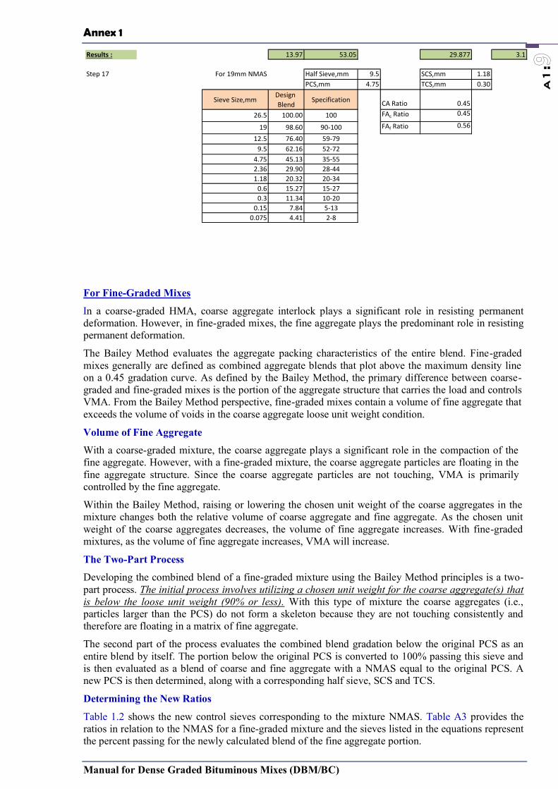
Annex 1
Manual for Dense Graded Bituminous Mixes (DBM/BC)
a1:
For Fine-Graded Mixes
In a coarse-graded HMA, coarse aggregate interlock plays a significant role in resisting permanent deformation. However, in fine-graded mixes, the fine aggregate plays the predominant role in resisting permanent deformation.
The Bailey Method evaluates the aggregate packing characteristics of the entire blend. Fine-graded mixes generally are defined as combined aggregate blends that plot above the maximum density line on a 0.45 gradation curve. As defined by the Bailey Method, the primary difference between coarse-graded and fine-graded mixes is the portion of the aggregate structure that carries the load and controls VMA. From the Bailey Method perspective, fine-graded mixes contain a volume of fine aggregate that exceeds the volume of voids in the coarse aggregate loose unit weight condition.
Volume of Fine Aggregate
With a coarse-graded mixture, the coarse aggregate plays a significant role in the compaction of the fine aggregate. However, with a fine-graded mixture, the coarse aggregate particles are floating in the fine aggregate structure. Since the coarse aggregate particles are not touching, VMA is primarily controlled by the fine aggregate.
Within the Bailey Method, raising or lowering the chosen unit weight of the coarse aggregates in the mixture changes both the relative volume of coarse aggregate and fine aggregate. As the chosen unit weight of the coarse aggregates decreases, the volume of fine aggregate increases. With fine-graded mixtures, as the volume of fine aggregate increases, VMA will increase.
The Two-Part Process
Developing the combined blend of a fine-graded mixture using the Bailey Method principles is a two-part process. The initial process involves utilizing a chosen unit weight for the coarse aggregate(s) that is below the loose unit weight (90% or less). With this type of mixture the coarse aggregates (i.e., particles larger than the PCS) do not form a skeleton because they are not touching consistently and therefore are floating in a matrix of fine aggregate.
The second part of the process evaluates the combined blend gradation below the original PCS as an entire blend by itself. The portion below the original PCS is converted to 100% passing this sieve and is then evaluated as a blend of coarse and fine aggregate with a NMAS equal to the original PCS. A new PCS is then determined, along with a corresponding half sieve, SCS and TCS.
Determining the New Ratios
Table 1.2 shows the new control sieves corresponding to the mixture NMAS. Table A3 provides the ratios in relation to the NMAS for a fine-graded mixture and the sieves listed in the equations represent the percent passing for the newly calculated blend of the fine aggregate portion.
Results : 13.97 53.05 29.877 3.1
Step 17 For 19mm NMAS Half Sieve,mm 9.5 SCS,mm 1.18PCS,mm 4.75 TCS,mm 0.30
Sieve Size,mmDesign Blend
Specification CA Ratio 0.4526.5 100.00 100 FAc Ratio 0.45
19 98.60 90-100 FAf Ratio 0.56
12.5 76.40 59-799.5 62.16 52-72
4.75 45.13 35-552.36 29.90 28-441.18 20.32 20-34
0.6 15.27 15-270.3 11.34 10-20
0.15 7.84 5-130.075 4.41 2-8
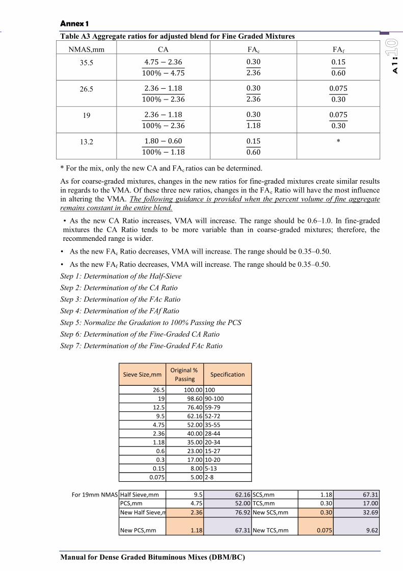
Annex 1
Manual for Dense Graded Bituminous Mixes (DBM/BC)
a1:
Table A3 Aggregate ratios for adjusted blend for Fine Graded Mixtures
NMAS,mm CA FAc FAf
35.5
−−
26.5
−−
19
−−
13.2
−−
*
* For the mix, only the new CA and FAc ratios can be determined.
As for coarse-graded mixtures, changes in the new ratios for fine-graded mixtures create similar results in regards to the VMA. Of these three new ratios, changes in the FAc Ratio will have the most influence in altering the VMA. The following guidance is provided when the percent volume of fine aggregate remains constant in the entire blend.
• As the new CA Ratio increases, VMA will increase. The range should be 0.6–1.0. In fine-graded mixtures the CA Ratio tends to be more variable than in coarse-graded mixtures; therefore, the recommended range is wider.
• As the new FAc Ratio decreases, VMA will increase. The range should be 0.35–0.50.
• As the new FAf Ratio decreases, VMA will increase. The range should be 0.35–0.50. Step 1: Determination of the Half-Sieve Step 2: Determination of the CA Ratio Step 3: Determination of the FAc Ratio Step 4: Determination of the FAf Ratio Step 5: Normalize the Gradation to 100% Passing the PCS Step 6: Determination of the Fine-Graded CA Ratio Step 7: Determination of the Fine-Graded FAc Ratio
Sieve Size,mmOriginal %
PassingSpecification
26.5 100.00 10019 98.60 90-100
12.5 76.40 59-799.5 62.16 52-72
4.75 52.00 35-552.36 40.00 28-441.18 35.00 20-34
0.6 23.00 15-270.3 17.00 10-20
0.15 8.00 5-130.075 5.00 2-8
For 19mm NMAS Half Sieve,mm 9.5 62.16 SCS,mm 1.18 67.31PCS,mm 4.75 52.00 TCS,mm 0.30 17.00New Half Sieve,mm 2.36 76.92 New SCS,mm 0.30 32.69
New PCS,mm 1.18 67.31 New TCS,mm 0.075 9.62
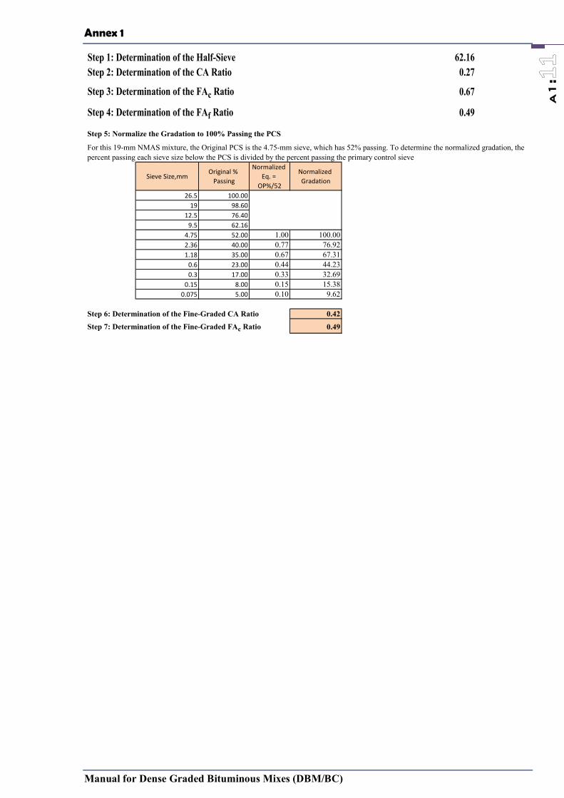
Annex 1
Manual for Dense Graded Bituminous Mixes (DBM/BC)
a1:
Step 1: Determination of the Half-Sieve 62.16Step 2: Determination of the CA Ratio 0.27
Step 3: Determination of the FAc Ratio 0.67
Step 4: Determination of the FAf Ratio 0.49
Step 5: Normalize the Gradation to 100% Passing the PCS
Sieve Size,mmOriginal %
Passing
Normalized Eq. =
OP%/52
Normalized Gradation
26.5 100.0019 98.60
12.5 76.409.5 62.16
4.75 52.00 1.00 100.002.36 40.00 0.77 76.921.18 35.00 0.67 67.31
0.6 23.00 0.44 44.230.3 17.00 0.33 32.69
0.15 8.00 0.15 15.380.075 5.00 0.10 9.62
Step 6: Determination of the Fine-Graded CA Ratio 0.42Step 7: Determination of the Fine-Graded FAc Ratio 0.49
For this 19-mm NMAS mixture, the Original PCS is the 4.75-mm sieve, which has 52% passing. To determine the normalized gradation, the percent passing each sieve size below the PCS is divided by the percent passing the primary control sieve
Annex 2
Manual for Dense Graded Bituminous Mixes (DBM/BC)
A2:
Annex-2 Asphalt Pavement Construction FAQs
Ref :
PRIME COATS
Q. What is a prime coat?
A. An application of a low viscosity asphalt to a granular base in preparation for an asphalt surface course.
Q. What is the purpose of a prime coat?
A. To coat and bond loose material particles on the surface of the base.
To harden or toughen the base surface to provide a work platform for construction equipment.
To plug capillary voids in the base course surface to prevent migration of moisture.
To provide adhesion between the base course and the succeeding course.
Q. What asphalt materials should be used for prime coats?
A. For a prime coat to be effective it must be able to penetrate into the base course. Usually a light grade of medium curing cutback such as an MC-30 will work well. However, in a lot of areas air quality is of concern and the EPA has restricted or eliminated the use of cutbacks. In such areas the use of an emulsified asphalt is necessary. There are several ways to accomplish a prime when using an emulsion:
1. Most emulsion manufacturers make proprietary products, one of which is an emulsion specifically designed for use in prime coats.
2. If the granular base material has a gradation that is somewhat porous, placing a prime coat can often be affected by placing a slow-setting emulsion (SS-1, SS-1 h, CSS-1, CSS-1 h) diluted 5 parts water to 1 part emulsion. By applying several (4 or 5) light applications (0.10 gal/sy), a waterproof surface can be obtained on the base course.
3. Incorporate an emulsion into the compaction water while placing the last 2 to 3 inches of the base course. Use a dilution and application rate which will provide 0.1 to 0.3 gallon per square yard (3:1 dilution; 4 applications; 0.15 gal/sy rate).
4. Complete placement of the base course material, then scarify up about 3/4 inch. Apply about 0.20 gal/sy 2 of straight emulsion (undiluted) and blade mix it with the scarified material. Then relay the mixed material and compact.
Q. Is a prime coat necessary?
A. At one time it was thought that a prime coat was an essential element of good pavement construction. However, in recent years some engineers have eliminated the use of a prime, especially when asphalt layer(s) (surface and/or base) is 4 inches or more in thickness. In many instances, prime coats have not been used even when surface thickness have been as thin as 2 inches. Over the past 20 years, few, if any, pavement failures can be attributed to the lack of prime coat.
Annex 2
Manual for Dense Graded Bituminous Mixes (DBM/BC)
A2:
TACK COATS
Q. Why is a tack coat needed?
A. To ensure a bond between the succeeding layers of a pavement.
Q. What material should be used for a tack coat?
A. A slow-setting emulsion, either SS-1, CSS-1, SS-I h, or CSS-1 h, works well when diluted 50/50 with water.
Q. What application rate should be used?
A. You want to accomplish a very uniform application of about 0.03 to 0.05 gal/sy of residual asphalt on the layer to be tacked (a paint job, so to speak). Slow-setting emulsions generally have a residual asphalt content of about 2/3. Therefore, an application rate of 0.10 to 0.15 gals/sy of the diluted material will give you the 0.03 to 0.05 gals/sy. Caution #1: Once the tack coat is applied, time must be allowed for emulsion to break (turn from brown to black) prior to placing hot mix on it. The length of time required for this to happen will depend on the weather. In good paving weather, it will take only a few minutes. In marginal weather it may take several minutes. Caution #2: Never apply an emulsion tack coat to a cold pavement (below the freezing point). The emulsion will break, but the water and emulsifying agents will freeze and remain in the layer that has been tack coated. If either of these cautions is violated, there is a good chance that upper layer will not bond to the under layer and a slip plane will develop.
Q. When is a tack coat necessary?
A. Almost always! On rare occasions when a pavement is being constructed which is not being used by traveling public and each succeeding lift is placed in rapid succesion, a tack coat may not be necessary. However, a good cheap insurance policy is to always use tack coats.
ASPHALT MIXTURES
Q: For an asphalt pavement in a container terminal, are there any rules of thumb as to what the maximum load could be without causing damage?
A: No rule of thumb answers your question, but two issues should be considered:
Is the pavement structure (subgrade, subbase, base, and all asphalt layers) adequate to support the loads? You need to purchase our MS-23 Manual, Thickness Design of Asphalt Pavements for Heavy Wheel Loads.
Is the hot mix asphalt surface stiff enough to resist deformation (ruts or indentations)? This is dependent on many factors, such as stiffness of the original mixture, age of the mix (gets stiffer over time), temperature of the mix during loading, loading itself, duration of applied load, etc. While not usually a problem, when it occurs it can typically be resolved by placing some steel (or other rigid material) plates below the point load to distribute the load across a wider area.
Q: Can the same paving equipment be used for Superpave mixes that was used for conventional mixes?
A: Yes. However, since Superpave mixes tend to be coarser and contain modified binders than conventional mixes, good construction practices are more important than ever. Segregation is more
Annex 2
Manual for Dense Graded Bituminous Mixes (DBM/BC)
A2:
likely to occur with coarser mixes if proper equipment and techniques are not used. Density can also be more difficult to achieve with Superpave mixes. Proper rolling techniques and adequate equipment are essential to achieve sufficient compaction. Breakdown rolling for Superpave mixes is normally done right behind the paver when the mix is hottest. Some contractors have found that additional and/or heavier rollers are sometimes needed. Pneumatic rubber-tired rollers work well, but tend to stick to the mat when polymer modified asphalt is used. Hand-working should be minimized. Sufficient well-graded (not segregated) material should be supplied by the paver augers to the joint to facilitate a low-void, low-permeability seam.
Q. Is there a problem with milling up and recycling asphalt mixes that used polymer modified binders?
A. Generally speaking, there are no unique problems with using polymer modified mixes as RAP. Some individuals express environmental concerns about running millings containing ground tire rubber (GTR) through a drum plant. Florida uses a small percentage of GTR on most of their highway surface mixes. California and Arizona also use GTR frequently.
Q. What is the proper mix temperature?
A. Mix temperature is dependent on the grade of asphalt used in the mix: Less viscous asphalt requires lower temperatures, while more viscous asphalt requiers higher temperatures. At the start of a mix design, target temperatures are specified for proper mixing and compaction. These temperatures should be adjusted for project conditions (weather, haul distances, etc.). If at all possible, avoid discrepancies from the mix design temperature of more than 25 degrees. Note: When working with modified binder, the binder supplier should provide mix temperature recommendations.
Q. What is a minimum temperature for asphalt mixes?
A. Mixes must be placed and compacted before they cool to 185o F, so the minimum temperature will depend on the temperature of the layer upon which it is being placed as well as ambient conditions. Generally, agency specifications will spell out a minimum acceptable temperature for the mix. Some specifications will use 225o F, and others may use 250o F.
Q. How do I ensure HMA is impervious to water?
A. Conventional mixes should be impervious to water as long as the total in-place air void content is below 7 to 8%. Mixes with higher void contents can be pervious to air and water leading to premature aging and raveling.
Q. Is there a limit on the percentage of RAP utilized in new installations? What about RAP use for resurfacing of old asphalt roads? Any limits? If there are limits on the use of RAP in new or resurfacing installations, who sets the limits?
A. The Asphalt Institute strongly endorses the use of RAP in asphalt mixtures. RAP has a history of positive performance. The specifying agency or owner will set the limit for RAP content. Almost all state highway departments now allow the use of RAP. A few restrict its use in wearing courses; even fewer (one or two) prohibit its use completely. Most agencies have developed a means of accomodating the stiffness of the reclaimed asphalt from the RAP by the selection of the particular grade of the virgin binder. The FHWA Asphalt Mixture Expert Task Group developed recommendations that are being considered by the Association of State Highway and Transportation Officials (AASHTO) to provide guidance in asphalt binder grade selection when using RAP. These recommendations are summarized below.
When 15% or less RAP is used: “The binder grade for the mixture is selected for the environment and traffic conditions the same as for a virgin mix. No grade adjustment is made to compensate for the stiffness of the asphalt in the RAP”.
When 16 to 25% RAP is used: “The selected binder grade for the new asphalt is one grade lower for both the high and low temperature stiffness than the binder grade required for a virgin asphalt. For example, if the specified binder grade for the virgin mix is a PG 64-22,

Annex 2
Manual for Dense Graded Bituminous Mixes (DBM/BC)
A2:
the required grade for the recycled mix would be a PG 58-28”.
When more than 25% RAP is used: “The binder grade for the new asphalt binder is selected using an appropriate blending chart for high and low temperature. The low temperature grade is one grade lower than the binder grade required for a virgin asphalt”.
Normally, the above guidelines would be applied to both new and existing pavements. If a warranty was applied to a project, a more conservative approach – such as the use of blending charts – might be taken.It is suggested that you contact the local state highway agency and/or asphalt binder supplier for the prevailing local practices.
Q. Is it acceptable to run Theoretical Maximum (Rice) Specific Gravity on material obtained from cores or saw cutting?
A. Rice (Gmm) is typically not run on material from cores as it is not the preferred method of material collection for this test. In fact, ASTM D5361, Standard Practice for Sampling Compacted Bituminous Mixtures for Laboratory Testing, does not include Rice testing in its Significance and Use section.
Note paragraph 3.1 from the standard reads: 3.1 Samples obtained in accordance with the procedure given in this practice may be used to measure pavement thickness, density, resilient or dynamic modulus, tensile strength, Marshall or Hveem stability, or for extraction testing, to determine asphalt content, asphalt properties and mix gradation. There are a couple of reasons for this. First, coring is naturally a destructive process which alters the gradation. The level to which the gradation shifts varies with the nature of the parent gradation and material. i.e., a half-inch SMA is likely to see a greater gradation shift then say a fine, dense-graded three-eighths mix. Secondly, and more importantly, by coring you are creating aggregate that is not coated with asphalt. This lack of coating can then allow for water absorption into these non-protected surfaces. Naturally, the more absorptive the aggregate the greater the potential issue with this situation. The AASHTO standard for Rice is T-209. It addresses absorption in part 15 of the standard entitled, “Supplemental Procedure for Mixtures Containing Porous Aggregate.” This is also known as the “dry-back procedure.” It is used on mixes produced with aggregate who’s water absorption is greater than 1.5%.However, while collection of Rice material via cores is not the preferred method, it is an acceptable method when more preferred alternatives (plant or lab produced samples) are not available. I am unaware of any state that does not allow for cores to be used for Gmm when no good alternative is an option. With the previous discussion in mind, one should do what they can to minimize any potential problems that may arise from field-cut specimens. What this leads to is a bigger is better mindset. A 6-inch core will have a smaller percentage of its aggregate affected by the coring than would a 4-inch core from the same road. Therefore, it is highly recommended that if alternative methods of producing materials for Rice are not an option, to use at least a 6-inch core. If a bigger specimen can be collected, such as saw-cutting, then it should be considered. Judgment, and locally acceptable practice, will certainly need to come into play.
AGGREGATE
Q. What is the proper nominal aggregate size to use?
A. Lift thickness governs aggregate size. Minimum lift thickness should be at least 3 times the nominal max. aggregate size to ensure aggregate can align themselves during compaction to achieve required density and also to ensure mix is impermeable. The maximum lift thickness is dependent also upon the type of compaction equipment that is being used. When static steel-wheeled rollers are used, the maximum lift thickness that can be properly compacted is three (3) inches. When pneumatic or vibratory rollers are used, the maximum thickness of lift that can be compacted is almost unlimited. Generally, lift thicknesses are limited to 6 or 8 inches. Proper placement becomes a problem in lifts thicker than 8 or 8 inches. For open-graded mixes, compaction is not an issue since it is intended that these types of mixes remain very open. Therefore, the maximum size aggregate can be as much as 80 percent of the lift thickness.
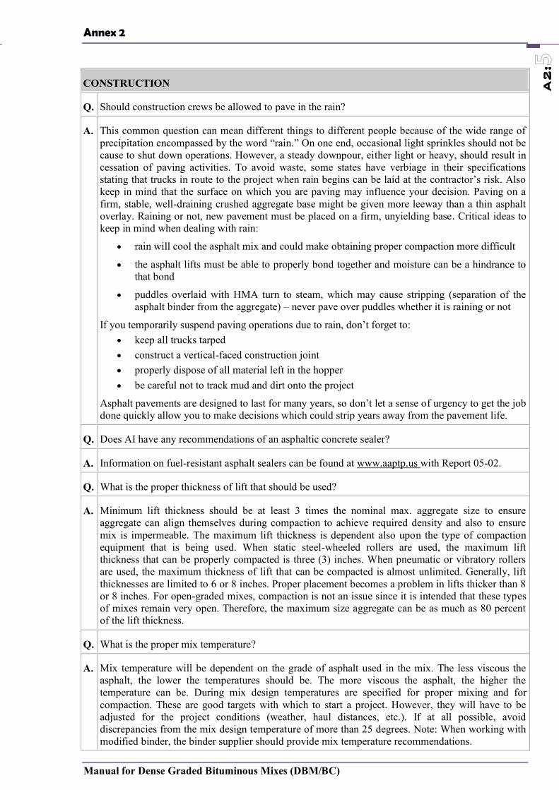
Annex 2
Manual for Dense Graded Bituminous Mixes (DBM/BC)
A2:
CONSTRUCTION
Q. Should construction crews be allowed to pave in the rain?
A. This common question can mean different things to different people because of the wide range of precipitation encompassed by the word “rain.” On one end, occasional light sprinkles should not be cause to shut down operations. However, a steady downpour, either light or heavy, should result in cessation of paving activities. To avoid waste, some states have verbiage in their specifications stating that trucks in route to the project when rain begins can be laid at the contractor’s risk. Also keep in mind that the surface on which you are paving may influence your decision. Paving on a firm, stable, well-draining crushed aggregate base might be given more leeway than a thin asphalt overlay. Raining or not, new pavement must be placed on a firm, unyielding base. Critical ideas to keep in mind when dealing with rain:
rain will cool the asphalt mix and could make obtaining proper compaction more difficult
the asphalt lifts must be able to properly bond together and moisture can be a hindrance to that bond
puddles overlaid with HMA turn to steam, which may cause stripping (separation of the asphalt binder from the aggregate) – never pave over puddles whether it is raining or not
If you temporarily suspend paving operations due to rain, don’t forget to: keep all trucks tarped construct a vertical-faced construction joint properly dispose of all material left in the hopper be careful not to track mud and dirt onto the project
Asphalt pavements are designed to last for many years, so don’t let a sense of urgency to get the job done quickly allow you to make decisions which could strip years away from the pavement life.
Q. Does AI have any recommendations of an asphaltic concrete sealer?
A. Information on fuel-resistant asphalt sealers can be found at www.aaptp.us with Report 05-02.
Q. What is the proper thickness of lift that should be used?
A. Minimum lift thickness should be at least 3 times the nominal max. aggregate size to ensure aggregate can align themselves during compaction to achieve required density and also to ensure mix is impermeable. The maximum lift thickness is dependent also upon the type of compaction equipment that is being used. When static steel-wheeled rollers are used, the maximum lift thickness that can be properly compacted is three (3) inches. When pneumatic or vibratory rollers are used, the maximum thickness of lift that can be compacted is almost unlimited. Generally, lift thicknesses are limited to 6 or 8 inches. Proper placement becomes a problem in lifts thicker than 8 or 8 inches. For open-graded mixes, compaction is not an issue since it is intended that these types of mixes remain very open. Therefore, the maximum size aggregate can be as much as 80 percent of the lift thickness.
Q. What is the proper mix temperature?
A. Mix temperature will be dependent on the grade of asphalt used in the mix. The less viscous the asphalt, the lower the temperatures should be. The more viscous the asphalt, the higher the temperature can be. During mix design temperatures are specified for proper mixing and for compaction. These are good targets with which to start a project. However, they will have to be adjusted for the project conditions (weather, haul distances, etc.). If at all possible, avoid discrepancies from the mix design temperature of more than 25 degrees. Note: When working with modified binder, the binder supplier should provide mix temperature recommendations.
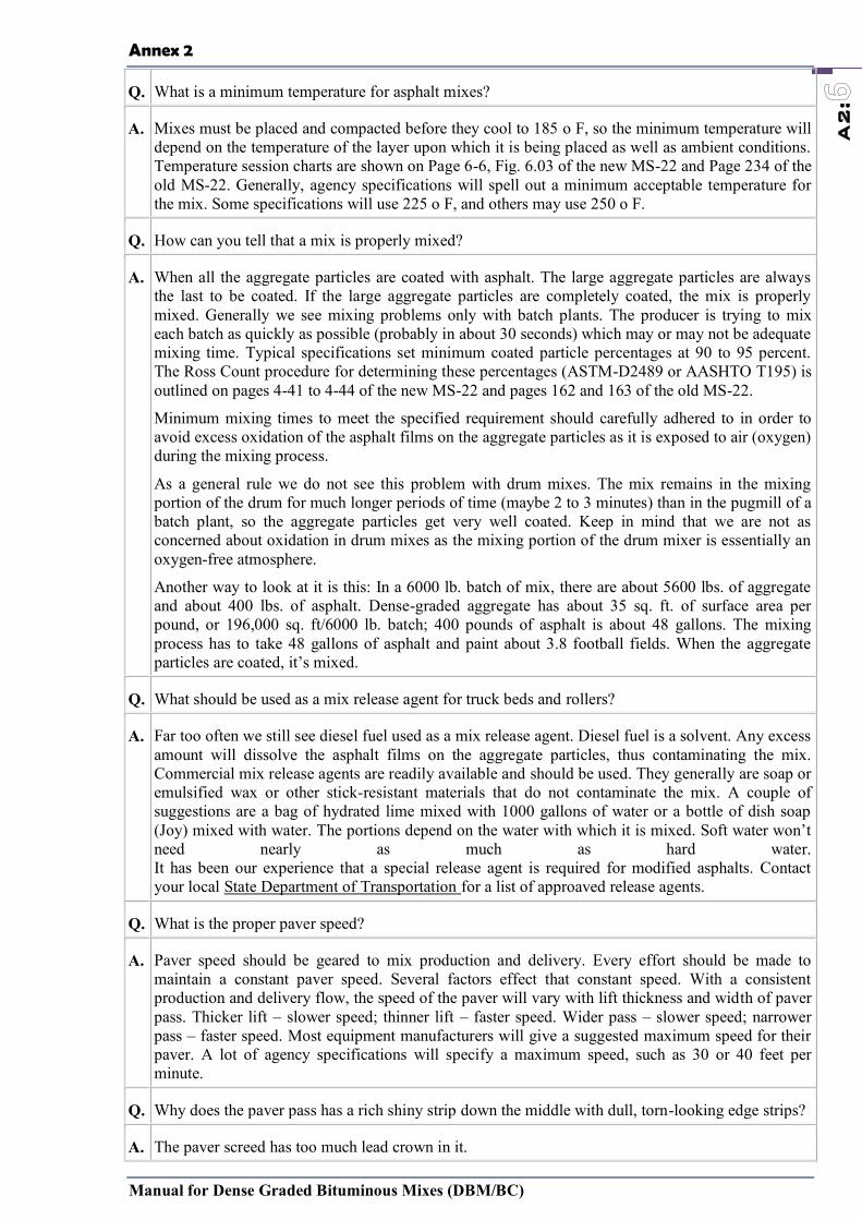
Annex 2
Manual for Dense Graded Bituminous Mixes (DBM/BC)
A2:
Q. What is a minimum temperature for asphalt mixes?
A. Mixes must be placed and compacted before they cool to 185 o F, so the minimum temperature will depend on the temperature of the layer upon which it is being placed as well as ambient conditions. Temperature session charts are shown on Page 6-6, Fig. 6.03 of the new MS-22 and Page 234 of the old MS-22. Generally, agency specifications will spell out a minimum acceptable temperature for the mix. Some specifications will use 225 o F, and others may use 250 o F.
Q. How can you tell that a mix is properly mixed?
A. When all the aggregate particles are coated with asphalt. The large aggregate particles are always the last to be coated. If the large aggregate particles are completely coated, the mix is properly mixed. Generally we see mixing problems only with batch plants. The producer is trying to mix each batch as quickly as possible (probably in about 30 seconds) which may or may not be adequate mixing time. Typical specifications set minimum coated particle percentages at 90 to 95 percent. The Ross Count procedure for determining these percentages (ASTM-D2489 or AASHTO T195) is outlined on pages 4-41 to 4-44 of the new MS-22 and pages 162 and 163 of the old MS-22.
Minimum mixing times to meet the specified requirement should carefully adhered to in order to avoid excess oxidation of the asphalt films on the aggregate particles as it is exposed to air (oxygen) during the mixing process.
As a general rule we do not see this problem with drum mixes. The mix remains in the mixing portion of the drum for much longer periods of time (maybe 2 to 3 minutes) than in the pugmill of a batch plant, so the aggregate particles get very well coated. Keep in mind that we are not as concerned about oxidation in drum mixes as the mixing portion of the drum mixer is essentially an oxygen-free atmosphere.
Another way to look at it is this: In a 6000 lb. batch of mix, there are about 5600 lbs. of aggregate and about 400 lbs. of asphalt. Dense-graded aggregate has about 35 sq. ft. of surface area per pound, or 196,000 sq. ft/6000 lb. batch; 400 pounds of asphalt is about 48 gallons. The mixing process has to take 48 gallons of asphalt and paint about 3.8 football fields. When the aggregate particles are coated, it’s mixed.
Q. What should be used as a mix release agent for truck beds and rollers?
A. Far too often we still see diesel fuel used as a mix release agent. Diesel fuel is a solvent. Any excess amount will dissolve the asphalt films on the aggregate particles, thus contaminating the mix. Commercial mix release agents are readily available and should be used. They generally are soap or emulsified wax or other stick-resistant materials that do not contaminate the mix. A couple of suggestions are a bag of hydrated lime mixed with 1000 gallons of water or a bottle of dish soap (Joy) mixed with water. The portions depend on the water with which it is mixed. Soft water won’t need nearly as much as hard water. It has been our experience that a special release agent is required for modified asphalts. Contact your local State Department of Transportation for a list of approaved release agents.
Q. What is the proper paver speed?
A. Paver speed should be geared to mix production and delivery. Every effort should be made to maintain a constant paver speed. Several factors effect that constant speed. With a consistent production and delivery flow, the speed of the paver will vary with lift thickness and width of paver pass. Thicker lift – slower speed; thinner lift – faster speed. Wider pass – slower speed; narrower pass – faster speed. Most equipment manufacturers will give a suggested maximum speed for their paver. A lot of agency specifications will specify a maximum speed, such as 30 or 40 feet per minute.
Q. Why does the paver pass has a rich shiny strip down the middle with dull, torn-looking edge strips?
A. The paver screed has too much lead crown in it.
Annex 2
Manual for Dense Graded Bituminous Mixes (DBM/BC)
A2:
Q. What causes the paver pass have rich shiny strips on each side and a dull, torn look in the middle?
A. The paver screed does not have enough lead crown in it. Note : Paver screeds should have slightly more crown in the leading edge than in the trailing edge – usually about 1/8 inch. This may very with equipment manufacturer and/or width of paver pass. Even if the trailing edge of the screed is to place a flat or straight grade, the leading edge must still have the increased crown.
Q. Is there a limit on the percentage of RAP utilized in new installations. What about RAP use for resurfacing of old asphalt roads? Any limits? If there are limits on the use of RAP in new or resurfacing installations, who sets the limits?
A. The Asphalt Institute strongly endorses the use of RAP in asphalt mixtures. RAP has a history of positive performance. Regarding limiting the RAP content, that is the decision of the specifying agency or owner. Almost all of the state highway departments now allow the use of RAP. A few restrict its use in wearing courses; even fewer (one or two) do not allow its use at all. Most agencies have developed a means of accomodating the stiffness of the reclaimed asphalt from the RAP by the selection of the particular grade of the virgin binder. The FHWA Asphalt Mixture Expert Task Group developed recommendations that are being considered by the Association of State Highway and Transportation Officials (AASHTO) to provide guidance in asphalt binder grade selection when using RAP. These recommendations are summarized below.
• When 15% or less RAP is used: “The binder grade for the mixture is selected for the environment and traffic conditions the same as for a virgin mix. No grade adjustment is made to compensate for the stiffness of the asphalt in the RAP”.
• When 16 to 25% RAP is used: “The selected binder grade for the new asphalt is one grade lower for both the high and low temperature stiffness than the binder grade required for a virgin asphalt. For example, if the specified binder grade for the virgin mix is a PG 64-22, the required grade for the recycled mix would be a PG 58-28”.
• When more than 25% RAP is used: “The binder grade for the new asphalt binder is selected using an appropriate blending chart for high and low temperature. The low temperature grade is one grade lower than the binder grade required for a virgin asphalt”.
Normally, the above guidelines would be applied to both new and existing pavements. If a warranty was applied to a project, a more conservative approach – such as the use of blending charts – might be taken.
It is suggested that you contact the local state highway agency and/or asphalt binder supplier for the prevailing local practices.
PLACEMENT
Q. Should construction crews be allowed to pave in the rain?
A. This common question can mean different things to different people because of the wide range of precipitation encompassed by the word “rain.” On one end, occasional light sprinkles should not be cause to shut down operations. However, a steady downpour, either light or heavy, should result in cessation of paving activities. To avoid waste, some states have verbiage in their specifications stating that trucks in route to the project when rain begins can be laid at the contractor’s risk. Also keep in mind that the surface on which you are paving may influence your decision. Paving on a firm, stable, well-draining crushed aggregate base might be given more leeway than a thin asphalt overlay. Raining or not, new pavement must be placed on a firm, unyielding base. Critical ideas to keep in mind when dealing with rain:
rain will cool the asphalt mix and could make obtaining proper compaction more difficult
the asphalt lifts must be able to properly bond together and moisture can be a hindrance to that bond

Annex 2
Manual for Dense Graded Bituminous Mixes (DBM/BC)
A2:
puddles overlaid with HMA turn to steam, which may cause stripping (separation of the asphalt binder from the aggregate) – never pave over puddles whether it is raining or not
If you temporarily suspend paving operations due to rain, don’t forget to:
keep all trucks tarped
construct a vertical-faced construction joint
properly dispose of all material left in the hopper
be careful not to track mud and dirt onto the project
Asphalt pavements are designed to last for many years, so don’t let a sense of urgency to get the job done quickly allow you to make decisions which could strip years away from the pavement life.
Q. Does AI have any recommendations of an asphaltic concrete sealer?
A. Information on fuel-resistant asphalt sealers can be found at www.aaptp.us with Report 05-02.
Q. How do I determine how much asphalt is required for a project?
A. Here’s the process: 1. Calculate the number of cubic feet to be paved. (Remember to convert the thickness to feet – by dividing by 12 inches per 1 foot). 10′ x 25′ x (4/12)’ = 83.3 cubic feet of HMA
2. Asphalt Mixture typically weighs from 142 to 148 pounds per cubic foot (PCF) in-place. Use 148 PCF.
3. Calculate the tonnage needed. (remember to convert from pounds to tons; 2000 pounds per ton).
83.3 cubic feet x 148 PCF = 12328 pounds of mix = 12328 / 2000 tons = 6.1 tons
Q: Can the same paving equipment be used for Superpave mixes that was used for conventional mixes?
A: Yes. However, since Superpave mixes do tend to be coarser and contain modified binders than conventional mixes, good construction practices are more important than ever. Segregation is more likely to occur with coarser mixes if proper equipment and techniques are not used. Density can also be more difficult to achieve with Superpave mixes. Proper rolling techniques and adequate equipment are essential to achieve sufficient compaction. Breakdown rolling for Superpave mixes is normally done right behind the paver when the mix is hottest. Some contractors have found that additional and/or heavier rollers are sometimes needed. Pneumatic rubber-tired rollers work well, but tend to stick to the mat when polymer modified asphalt is used.Hand-working should be minimized. Sufficient well-graded (not segregated) material should be supplied by the paver augers to the joint to facilitate a low void, low permeability seam.
Q. What is the proper paver speed?
A. Paver speed should be geared to mix production, delivery and compaction; with emphasis placed on compaction. Every effort should be made to maintain a constant paver speed. Several factors effect that constant speed. With a consistent production and delivery flow, the speed of the paver will vary with lift thickness (thicker/slower; thinner/faster) and width of paver pass wider/slower; narrow/faster). Most equipment manufacturers will give a suggested maximum speed for their paver. A lot of agency specifications will specify a maximum speed, such as 30 or 40 feet per minute. Most compaction manufacturers recommend a maximum roller speed of 3 mph and most often more than one roller pass is needed to get compaction. Therefore, the number and type of rollers being used is very important.
Q. Is it ok to cool down the laid mat immediately using water for early traffic?
A. We do not recommend spraying water on freshly laid hot mix asphalt (HMA) in order to cool the mat faster and open to traffic sooner. First, spraying water on the hot mat is not very effective since
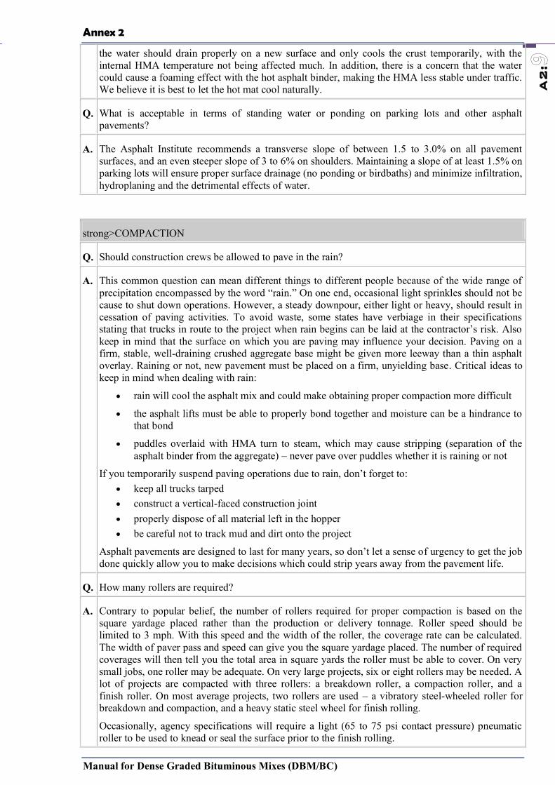
Annex 2
Manual for Dense Graded Bituminous Mixes (DBM/BC)
A2:
the water should drain properly on a new surface and only cools the crust temporarily, with the internal HMA temperature not being affected much. In addition, there is a concern that the water could cause a foaming effect with the hot asphalt binder, making the HMA less stable under traffic. We believe it is best to let the hot mat cool naturally.
Q. What is acceptable in terms of standing water or ponding on parking lots and other asphalt pavements?
A. The Asphalt Institute recommends a transverse slope of between 1.5 to 3.0% on all pavement surfaces, and an even steeper slope of 3 to 6% on shoulders. Maintaining a slope of at least 1.5% on parking lots will ensure proper surface drainage (no ponding or birdbaths) and minimize infiltration, hydroplaning and the detrimental effects of water.
strong>COMPACTION
Q. Should construction crews be allowed to pave in the rain?
A. This common question can mean different things to different people because of the wide range of precipitation encompassed by the word “rain.” On one end, occasional light sprinkles should not be cause to shut down operations. However, a steady downpour, either light or heavy, should result in cessation of paving activities. To avoid waste, some states have verbiage in their specifications stating that trucks in route to the project when rain begins can be laid at the contractor’s risk. Also keep in mind that the surface on which you are paving may influence your decision. Paving on a firm, stable, well-draining crushed aggregate base might be given more leeway than a thin asphalt overlay. Raining or not, new pavement must be placed on a firm, unyielding base. Critical ideas to keep in mind when dealing with rain:
rain will cool the asphalt mix and could make obtaining proper compaction more difficult
the asphalt lifts must be able to properly bond together and moisture can be a hindrance to that bond
puddles overlaid with HMA turn to steam, which may cause stripping (separation of the asphalt binder from the aggregate) – never pave over puddles whether it is raining or not
If you temporarily suspend paving operations due to rain, don’t forget to: keep all trucks tarped construct a vertical-faced construction joint properly dispose of all material left in the hopper be careful not to track mud and dirt onto the project
Asphalt pavements are designed to last for many years, so don’t let a sense of urgency to get the job done quickly allow you to make decisions which could strip years away from the pavement life.
Q. How many rollers are required?
A. Contrary to popular belief, the number of rollers required for proper compaction is based on the square yardage placed rather than the production or delivery tonnage. Roller speed should be limited to 3 mph. With this speed and the width of the roller, the coverage rate can be calculated. The width of paver pass and speed can give you the square yardage placed. The number of required coverages will then tell you the total area in square yards the roller must be able to cover. On very small jobs, one roller may be adequate. On very large projects, six or eight rollers may be needed. A lot of projects are compacted with three rollers: a breakdown roller, a compaction roller, and a finish roller. On most average projects, two rollers are used – a vibratory steel-wheeled roller for breakdown and compaction, and a heavy static steel wheel for finish rolling.
Occasionally, agency specifications will require a light (65 to 75 psi contact pressure) pneumatic roller to be used to knead or seal the surface prior to the finish rolling.

Annex 2
Manual for Dense Graded Bituminous Mixes (DBM/BC)
A2:
Q. What is the recommended air void content for compaction of asphalt pavements?
A. Efforts should be made to control compacted air voids between 7% and 3%. At 8% or higher, interconnected voids which allow air and moisture to permeate the pavement, reducing its durability. On the other hand, if air voids fall below 3%, there will be inadequate room for expansion of the asphalt binder in hot weather. When the void content drops to 2% or less, the mix becomes plastic and unstable.
Q. How is air void content controlled?
A. Air voids are a reverse proportion of the density of the compacted mix. By specifying a density requirement, the voids are inversely controlled. Keep in mind that density is a relative term, compared to a target density of either lab compacted mix, a maximum theoretical density, or a control strip density. Procedures for using the three methods are spelled out on Page 7-17 to 7-21 of the new MS-22 and Page 241 of the old MS-22.
Q. What should compaction requirements be?
A. Testing should be done on a random sampling basis with a minimum of five tests per lot (agency requirements define a “lot” as “A day’s or full day’s production”). The average of the five density determinations should be equal to or greater than: 1) 96% of lab density with no test less than 94% 2) 92% of maximum theoretical with no test less than 90%.
3) 99% of the control strip density
Q. What is the best way to check density?
A. Nuclear gauges are generally used for density testing because of the ease and speed with which the testing can be done. This allows for many more tests – more than the five minimum for a better statistical result. Caution : The nuclear density gauge needs to be correlated to core densities that are taken from the same location as was nuclear gauge tested. This should be done for each different mix that might be used.
Q. How do the lab-compacted air voids of “reheated” asphalt mixture samples compare to the air voids of “original” mixture samples (as-produced, not reheated)?
A. There is not a predictable value or “rule-of-thumb number” for the difference in air void content of original and reheated samples. The general trend would be for the reheated samples to have higher air voids than the original, compacted specimens. Absorption and hardening or stiffening of the asphalt binder in the reheated samples likely causes this difference. Reheated samples can be utilized to give an overall check of the original sample results. Before any significant precision is attributed to reheated sample results, a correlation should be developed for reheated sample air voids and original sample air voids by performing a series of comparative tests.
Q. What might cause surface cracking on newly placed asphalt concrete? The cracking occurred during the breakdown rolling and finish rolling.
A. Without knowing what the surface cracking looks like, it is hard for us to identify the problem. Could the “surface cracking” be checking cracking from the rolling operation? It is shallow hairline surface cracks spaced an inch or two apart from each other and running transverse to the direction of rolling. The cause is rolling on the mat too hot and/or too tender of a mix. You can reference page 6-9 of the new MS-22 and page 219-220 of the old MS-22 manual if you are not sure what checking is.
Q: Can the same paving equipment be used for Superpave mixes that was used for conventional mixes?
A: Yes. However, since Superpave mixes do tend to be coarser and contain modified binders than
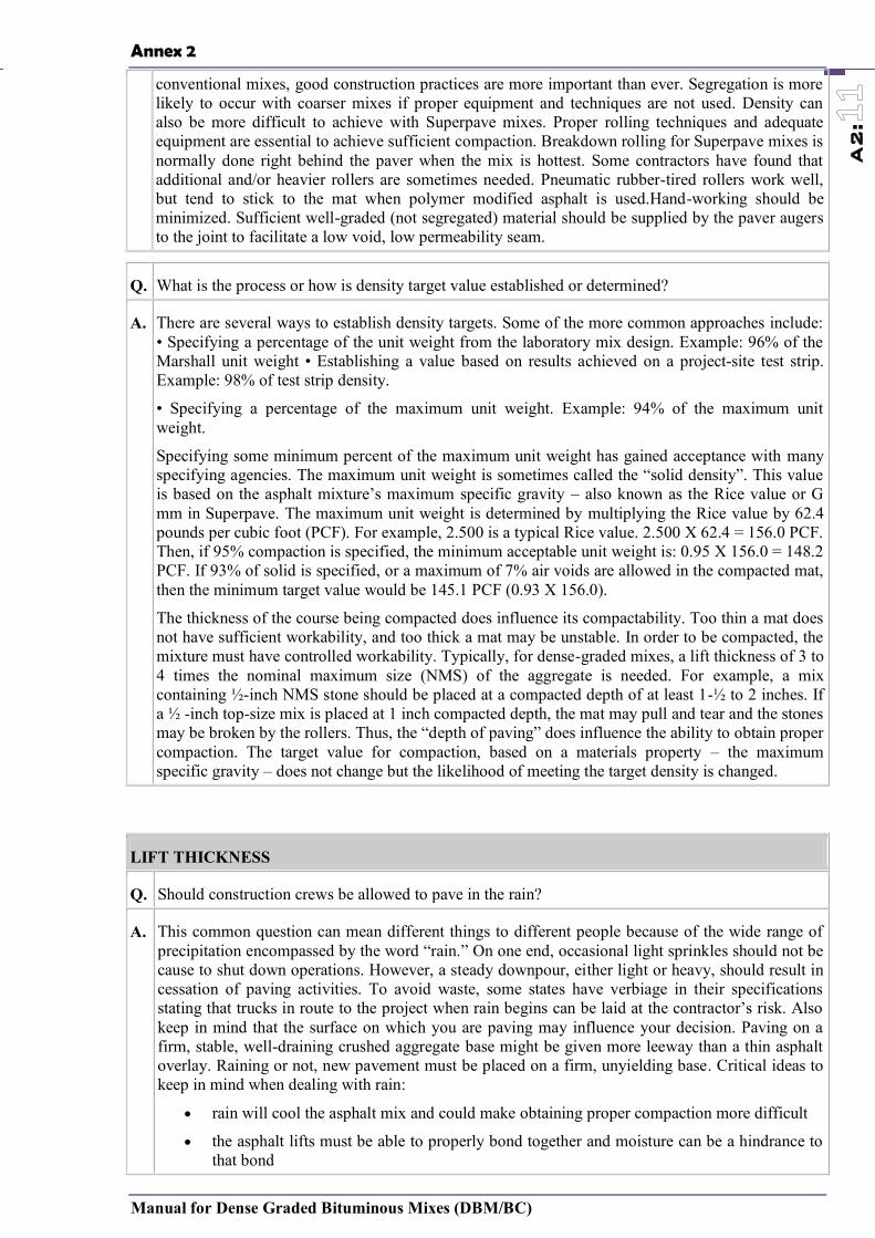
Annex 2
Manual for Dense Graded Bituminous Mixes (DBM/BC)
A2:
conventional mixes, good construction practices are more important than ever. Segregation is more likely to occur with coarser mixes if proper equipment and techniques are not used. Density can also be more difficult to achieve with Superpave mixes. Proper rolling techniques and adequate equipment are essential to achieve sufficient compaction. Breakdown rolling for Superpave mixes is normally done right behind the paver when the mix is hottest. Some contractors have found that additional and/or heavier rollers are sometimes needed. Pneumatic rubber-tired rollers work well, but tend to stick to the mat when polymer modified asphalt is used.Hand-working should be minimized. Sufficient well-graded (not segregated) material should be supplied by the paver augers to the joint to facilitate a low void, low permeability seam.
Q. What is the process or how is density target value established or determined?
A. There are several ways to establish density targets. Some of the more common approaches include: • Specifying a percentage of the unit weight from the laboratory mix design. Example: 96% of the Marshall unit weight • Establishing a value based on results achieved on a project-site test strip. Example: 98% of test strip density.
• Specifying a percentage of the maximum unit weight. Example: 94% of the maximum unit weight.
Specifying some minimum percent of the maximum unit weight has gained acceptance with many specifying agencies. The maximum unit weight is sometimes called the “solid density”. This value is based on the asphalt mixture’s maximum specific gravity – also known as the Rice value or G mm in Superpave. The maximum unit weight is determined by multiplying the Rice value by 62.4 pounds per cubic foot (PCF). For example, 2.500 is a typical Rice value. 2.500 X 62.4 = 156.0 PCF. Then, if 95% compaction is specified, the minimum acceptable unit weight is: 0.95 X 156.0 = 148.2 PCF. If 93% of solid is specified, or a maximum of 7% air voids are allowed in the compacted mat, then the minimum target value would be 145.1 PCF (0.93 X 156.0).
The thickness of the course being compacted does influence its compactability. Too thin a mat does not have sufficient workability, and too thick a mat may be unstable. In order to be compacted, the mixture must have controlled workability. Typically, for dense-graded mixes, a lift thickness of 3 to 4 times the nominal maximum size (NMS) of the aggregate is needed. For example, a mix containing ½-inch NMS stone should be placed at a compacted depth of at least 1-½ to 2 inches. If a ½ -inch top-size mix is placed at 1 inch compacted depth, the mat may pull and tear and the stones may be broken by the rollers. Thus, the “depth of paving” does influence the ability to obtain proper compaction. The target value for compaction, based on a materials property – the maximum specific gravity – does not change but the likelihood of meeting the target density is changed.
LIFT THICKNESS
Q. Should construction crews be allowed to pave in the rain?
A. This common question can mean different things to different people because of the wide range of precipitation encompassed by the word “rain.” On one end, occasional light sprinkles should not be cause to shut down operations. However, a steady downpour, either light or heavy, should result in cessation of paving activities. To avoid waste, some states have verbiage in their specifications stating that trucks in route to the project when rain begins can be laid at the contractor’s risk. Also keep in mind that the surface on which you are paving may influence your decision. Paving on a firm, stable, well-draining crushed aggregate base might be given more leeway than a thin asphalt overlay. Raining or not, new pavement must be placed on a firm, unyielding base. Critical ideas to keep in mind when dealing with rain:
rain will cool the asphalt mix and could make obtaining proper compaction more difficult
the asphalt lifts must be able to properly bond together and moisture can be a hindrance to that bond

Annex 2
Manual for Dense Graded Bituminous Mixes (DBM/BC)
A2:
puddles overlaid with HMA turn to steam, which may cause stripping (separation of the asphalt binder from the aggregate) – never pave over puddles whether it is raining or not
If you temporarily suspend paving operations due to rain, don’t forget to:
keep all trucks tarped
construct a vertical-faced construction joint
properly dispose of all material left in the hopper
be careful not to track mud and dirt onto the project
Asphalt pavements are designed to last for many years, so don’t let a sense of urgency to get the job done quickly allow you to make decisions which could strip years away from the pavement life.
Q: Can the same paving equipment be used for Superpave mixes that was used for conventional mixes?
A: Yes. However, since Superpave mixes do tend to be coarser and contain modified binders than conventional mixes, good construction practices are more important than ever. Segregation is more likely to occur with coarser mixes if proper equipment and techniques are not used. Density can also be more difficult to achieve with Superpave mixes. Proper rolling techniques and adequate equipment are essential to achieve sufficient compaction. Breakdown rolling for Superpave mixes is normally done right behind the paver when the mix is hottest. Some contractors have found that additional and/or heavier rollers are sometimes needed. Pneumatic rubber-tired rollers work well, but tend to stick to the mat when polymer modified asphalt is used. Hand-working should be minimized. Sufficient well-graded (not segregated) material should be supplied by the paver augers to the joint to facilitate a low void, low permeability seam.
Q. What is the recommended minimum lift thickness for placing HMA?
A. Minimum lift thickness should be at least 3 times the nominal maximum aggregate size to ensure aggregates can align themselves during compaction to achieve required density and also to ensure mix is impermeable. The maximum lift thickness is also dependent on the type of compaction equipment being used. When static steel-wheeled rollers are used, the maximum lift thickness that can be properly compacted is 3 inches. When pneumatic or vibratory roller is used, the maximum lift thickness that can be compacted is almost unlimited. Generally, lift thicknesses are limited to 6 or 8 inches. Proper placement becomes a problem in lifts thicker than 6 or 8 inches. For open-graded mixes, compaction is not an issue since it is intended that these types of mixes remain very open. Therefore, the maximum size aggregate can be as much as 80 percent of the lift thickness.
WEATHER
Q. Should construction crews be allowed to pave in the rain?
A. This common question can mean different things to different people because of the wide range of precipitation encompassed by the word “rain.” On one end, occasional light sprinkles should not be cause to shut down operations. However, a steady downpour, either light or heavy, should result in cessation of paving activities. To avoid waste, some states have verbiage in their specifications stating that trucks in route to the project when rain begins can be laid at the contractor’s risk. Also keep in mind that the surface on which you are paving may influence your decision. Paving on a firm, stable, well-draining crushed aggregate base might be given more leeway than a thin asphalt overlay. Raining or not, new pavement must be placed on a firm, unyielding base. Critical ideas to keep in mind when dealing with rain:
rain will cool the asphalt mix and could make obtaining proper compaction more difficult
the asphalt lifts must be able to properly bond together and moisture can be a hindrance to that bond
puddles overlaid with HMA turn to steam, which may cause stripping (separation of the
Annex 2
Manual for Dense Graded Bituminous Mixes (DBM/BC)
A2:
asphalt binder from the aggregate) – never pave over puddles whether it is raining or not If you temporarily suspend paving operations due to rain, don’t forget to:
keep all trucks tarped construct a vertical-faced construction joint properly dispose of all material left in the hopper be careful not to track mud and dirt onto the project
Asphalt pavements are designed to last for many years, so don’t let a sense of urgency to get the job done quickly allow you to make decisions which could strip years away from the pavement life.
Q. Can asphalt be applied in the rain (light drizzle)?
A. It is not avisable to start paving if it is raining. If rain starts after paving has begun, the work can continue as long as there is no standing water and the rain is not too hard. The primary concern is achieving adequate compaction, as the mix will cool much faster due to evaporative cooling if laid on a wet surface or rain falls on an uncompacted mat. Additional compactive effort will be needed and monitoring temperatures is key to acheiving adequate density.
PLANT OPERATIONS
Q. Is there a problem with milling up and recycling asphalt mixes that used polymer modified binders?
A. Generally speaking, there are no unique problems with using polymer modified mixes as RAP. Some individuals express environmental concerns about running millings containing ground tire rubber (GTR) through a drum plant. Florida uses a small percentage of GTR on most of their highway surface mixes. California and Arizona also use GTR frequently.
Q. How can you tell that a mix is properly mixed?
A. When all the aggregate particles are coated with asphalt. The large aggregate particles are always the last to be coated. If the large aggregate particles are completely coated, the mix is properly mixed. Generally we see mixing problems only with batch plants, where the producer miesx each batch as quickly as possible (probably in about 30 seconds), which may or may not be adequate mixing time. Typical specifications set minimum coated particle percentages at 90 to 95 percent. The Ross Count procedure for determining these percentages (ASTM-D2489 or AASHTO T195) is outlined on pages 4-41 to 4-44 of the new MS-22 and pages 162 and 163 of the old MS-22.
Minimum mixing times to meet the specified requirement should be carefully adhered to in order to avoid excess oxidation of the asphalt films on the aggregate particles as it is exposed to air (oxygen) during the mixing process.
As a general rule we do not see this problem with drum mixes. The mix remains in the mixing portion of the drum for much longer periods of time (maybe 2 to 3 minutes) than in the pugmill of a batch plant, so the aggregate particles get very well coated. Keep in mind that we are not as concerned about oxidation in drum mixes as the mixing portion of the drum mixer is essentially an oxygen-free atmosphere.
Another way to look at it is this: In a 6000 lb. batch of mix, there are about 5600 lbs. of aggregate and about 400 lbs. of asphalt. Dense-graded aggregate has about 35 sq. ft. of surface area per pound, or 196,000 sq. ft/6000 lb. batch; 400 pounds of asphalt is about 48 gallons. The mixing process has to take 48 gallons of asphalt and paint about 3.8 football fields. When the aggregate particles are coated, it’s mixed.
INTERSECTIONS
Q. How do you design a good quality asphalt instersection?
A. The tools now exist to gain improved performance from HMA intersections. Well-designed, properly constructed HMA intersections provide an economical, long-lasting pavement with

Annex 2
Manual for Dense Graded Bituminous Mixes (DBM/BC)
A2:
minimal disruption to traffic.In order to achieve these benefits, we must recognize that intersection pavements are subject to extreme stresses. Ordinary materials and techniques may not be sufficient. There must be adequate pavement structure, select materials, appropriate construction techniques, and careful attention to detail in the process.To learn more about how to design and build high performance HMA intersections see the following series of ASPHALT magazine articles.
Intersection Strategy 1: Developing a Strategy for Better Performing Intersection Pavements (PDF 692 kb)
Intersection Strategy 2: Ensuring Structural Adequacy-A Key Step to Intersection Strategies (PDF 664 kb)
Intersection Strategy 3: Materials and Construction Concerns for Improved Intersection Performance (PDF 655 kb)
Intersection Strategy 4: Three Examples of Implementing the Plan
World’s Strongest Intersection (PDF 483 kb)
Q: For an asphalt pavement in a container terminal, is there any rules of thumb as to what the maximum load could be without causing damage?
A: No rule of thumb answers your question. There are two issues:
Is the pavement structure (subgrade, subbase, base, and all asphalt layers) adequate to support the loads? You need to purchase our MS-23 Manual, Thickness Design of Asphalt Pavements for Heavy Wheel Loads.
Is the hot mix asphalt surface stiff enough to resist deformation (ruts or indentations)? This is dependent on many factors, such as stiffness of the original mixture, age of the mix (gets stiffer over time), temperature of the mix during loading, loading itself, duration of applied load, etc. This is generally not a problem, but if it is, can typically be resolved by placing some steel (or other rigid material) plates below the point load to distribute the load across a wider area.
Q. How do the lab-compacted air voids of “reheated” asphalt mixture samples compare to the air voids of “original” mixture samples (as-produced, not reheated)?
A. There is not a predictable value or “rule-of-thumb number” for the difference in air void content of original and reheated samples. The general trend would be for the reheated samples to have higher air voids than the original, compacted specimens. Absorption and hardening or stiffening of the asphalt binder in the reheated samples likely causes this difference.
Reheated samples can be utilized to give an overall check of the original sample results. Before any significant precision is attributed to reheated sample results, a correlation should be developed for reheated sample air voids and original sample air voids by performing a series of comparative tests.
Q. Is there a problem with milling up and recycling asphalt mixes that used polymer modified binders?
A. Generally speaking, there should be no unique problems with using polymer modified mixes as RAP. There have been some individuals express environmental concerns about running millings containing ground tire rubber (GTR) through a drum plant. Florida uses a small percentage of GTR on most of their highway surface mixes. California and Arizona also use GTR frequently.
Q. What is the proper mix temperature?
A. Mix temperature will be dependent on the grade of asphalt used in the mix. The less viscous the asphalt, the lower the temperatures should be. The more viscous the asphalt, the higher the temperature can be. During mix design temperatures are specified for proper mixing and for compaction. These are good targets with which to start a project. However, they will have to be adjusted for the project conditions (weather, haul distances, etc.). If at all possible, avoid
Annex 2
Manual for Dense Graded Bituminous Mixes (DBM/BC)
A2:
discrepancies from the mix design temperature of more than 25 degrees. Note: When working with modified binder, the binder supplier should provide mix temperature recommendations.
SURFACE TREATMENTS
Q. Does AI have any recommendations of an asphaltic concrete sealer?
A. Information on fuel-resistant asphalt sealers can be found at www.aaptp.us with Report 05-02.
Q. What type asphalt should be used?
A. A liquid asphalt, such as a Rapid Setting Emulsion (RS-1,2 or CRS-1,2 includes modified) 1 Cutback asphalts in some areas depending on EPA regulations which would include RC-250, 800 or 3000, are normally used. Highly skilled crews could also use an AC-5 or 10.
Q. How much asphalt should be applied to the aggregate? (chips)
A. The amount of asphalt applied depends on three factors: 1) The existing surface condition, 2) the amount of traffic, and
3) the average particle size of the chips. Allowance should be made for surface conditions – dry, pocked, badly cracked, flushed, bleeding, etc. Lower traffic volumes require higher asphalt applications than higher traffic. The average particle size should be embedded 60-75% into the asphalt. Higher traffic should be closer to the 60% and lower traffic should be closer to the 75% embedment factor. The average particle size is the average size of chip in the gradation, the 50% passing size can be used for this number.
Q. Do the chips need to be clean?
A. Yes – AASHTO T-11 Dust ratio should be less than 0.75
Q. What causes roadway streaking in chip seals?
A. Several factors can lead to this appearance; improper distributor nozzle sizes, pump pressure, spray bar height, angle of nozzle, and cold asphalt.
MIX RELEASE AGENTS
Q. What should be used as a mix release agent for truck beds and rollers?
A. Far too often we still see diesel fuel used as a mix release agent. Diesel fuel is a solvent. Any excess amount will dissolve the asphalt films on the aggregate particles, thus contaminating the mix. Commercial mix release agents are readily available and should be used. They generally are soap or emulsified wax or other stick-resistant materials that do not contaminate the mix. It has been our experience that a special release agent is required for modified asphalts. Contact your local State Department of Transportation for a list of approved release agents.
SPECIAL APPLICATIONS
Q. Does AI have any recommendations of an asphaltic concrete sealer?
A. Information on fuel-resistant asphalt sealers can be found at www.aaptp.us with Report 05-02.
Q. Is there a way to color an asphalt pavement other than shades of black and grey?
Annex 2
Manual for Dense Graded Bituminous Mixes (DBM/BC)
A2:
A. While not widely used, there are ways to color an asphalt pavement other than the common blacks and greys. The second and third options are considered specialty products and more information can be obtained by contacting individual manufacturers.
Use a naturally colored aggregate. As the asphalt binder wears way from the surface with traffic, the color of the aggregate is exposed.
Use an additive in the asphalt binder. Various iron compounds can impart a red, green, yellow or orange tint to a pavement, while other colors can be achieved using different metal additives. A special “synthetic” binder that contains no asphaltenes has been used because it takes color more readily. This method of tinting the mix allows color to permeate the entire depth of the material, so there are no surface wear-off concerns.
Coat the surface with a material that penetrates the voids and bonds well to asphalt pavement, such as an epoxy-fortified acrylic emulsion. Many colors are available. Care should be taken to ensure that surface friction is not compromised, especially if the pavement is used for vehicular traffic. One possible disadvantage of this method is that the surface may wear off with time and need to be renewed.
Q: For an asphalt pavement in a container terminal, is there any rules of thumb as to what the maximum load could be without causing damage?
A: No rule of thumb answers to your question. There are two issues:
Is the pavement structure (subgrade, subbase, base, and all asphalt layers) adequate to support the loads? You need to purchase our MS-23 Manual, Thickness Design of Asphalt Pavements for Heavy Wheel Loads.
Is the hot mix asphalt surface stiff enough to resist deformation (ruts or indentations)? This is dependent on many factors, such as stiffness of the original mixture, age of the mix (gets stiffer over time), temperature of the mix during loading, loading itself, duration of applied load, etc. This is generally not a problem, but if it is, can typically be resolved by placing some steel (or other rigid material) plates below the point load to distribute the load across a wider area.
Q. How do the lab-compacted air voids of “reheated” asphalt mixture samples compare to the air voids of “original” mixture samples (as-produced, not reheated)?
A. There is not a predictable value or “rule-of-thumb number” for the difference in air void content of original and reheated samples. The general trend would be for the reheated samples to have higher air voids than the original, compacted specimens. Absorption and hardening or stiffening of the asphalt binder in the reheated samples likely causes this difference.
Reheated samples can be utilized to give an overall check of the original sample results. Before any significant precision is attributed to reheated sample results, a correlation should be developed for reheated sample air voids and original sample air voids by performing a series of comparative tests.
TROUBLESHOOTING
Q. Should construction crews be allowed to pave in the rain?
A. This common question can mean different things to different people because of the wide range of precipitation encompassed by the word “rain.” On one end, occasional light sprinkles should not be cause to shut down operations. However, a steady downpour, either light or heavy, should result in cessation of paving activities. To avoid waste, some states have verbiage in their specifications stating that trucks in route to the project when rain begins can be laid at the contractor’s risk. Also keep in mind that the surface on which you are paving may influence your decision. Paving on a firm, stable, well-draining crushed aggregate base might be given more leeway than a thin asphalt overlay. Raining or not, new pavement must be placed on a firm, unyielding base. Critical ideas to
Annex 2
Manual for Dense Graded Bituminous Mixes (DBM/BC)
A2:
keep in mind when dealing with rain: rain will cool the asphalt mix and could make obtaining proper compaction more difficult the asphalt lifts must be able to properly bond together and moisture can be a hindrance to that bond puddles overlaid with HMA turn to steam, which may cause stripping (separation of the asphalt binder from the aggregate) – never pave over puddles whether it is raining or not If you temporarily suspend paving operations due to rain, don’t forget to: keep all trucks tarped construct a vertical-faced construction joint properly dispose of all material left in the hopper be careful not to track mud and dirt onto the project Asphalt pavements are designed to last for many years, so don’t let a sense of urgency to get the job done quickly allow you to make decisions which could strip years away from the pavement life.
Q. Does AI have any recommendations of an asphaltic concrete sealer?
A. Information on fuel-resistant asphalt sealers can be found at www.aaptp.us with Report 05-02.
Q. What causes tire scuffing and what should be done about it?
A. See the following pdf document: Position Paper – Tire Scuffing & Indentations by the Ontario Hot Mix Producers Association
Q. The paver pass has a rich shiny strip down the middle with dull, torn-looking edge strips.
A. The paver screed has too much lead crown in it.
Q. What causes the paver pass to have rich shiny strips on each side and a dull, torn look in the middle.
A. The paver screed does not have enough lead crown in it. Note : Paver screeds should have slightly more crown in the leading edge than in the trailing edge – usually about 1/8 inch. This may very with equipment manufacturer and/or width of paver pass. Even if the trailing edge of the screed is to place a flat or straight grade, the leading edge must still have the increased crown.
Q: Can the same paving equipment be used for Superpave mixes that was used for conventional mixes.
A: Yes. However, since Superpave mixes do tend to be coarser and contain modified binders more often than conventional mixes, good construction practices are more important than ever. Segregation is more likely to occur with coarser mixes if proper equipment and techniques are not used. Density can also be more difficult to achieve with Superpave mixes. Proper rolling techniques and adequate equipment are essential to achieve sufficient compaction. Breakdown rolling for Superpave mixes is normally done right behind the paver when the mix is hottest. Some contractors have found that additional and/or heavier rollers are sometimes needed. Pneumatic rubber-tired rollers work well, but tend to stick to the mat when polymer modified asphalt is used. Hand-working should be minimized. Sufficient well-graded (not segregated) material should be supplied by the paver augers to the joint to facilitate a low void, low permeability seam.
Q. What might cause surface cracking on newly placed asphalt concrete? The cracking occurred during the breakdown rolling and finish rolling.
A. Without knowing what the surface cracking looks like, it is hard for us to identify the problem. Could the “surface cracking” be check cracking from the rolling operation? “Checking is the development of shallow hairline surface cracks spaced an inch or two apart from each other and running transverse to the direction of rolling. The cause is rolling when the mat too hot and/or the mix is too tender. You can reference our page 6-6 of the new MS-22 manual and page 219 & 220 of the old MS-22 if you are not sure what check cracking is.

Annex 3
Manual for Dense Graded Bituminous Mixes (DBM/BC)
A3:
Annex 3 Best Practices of HMA
Limits ability to implement Best Practice
o Funding o Weather o Space o Right of way o Antecedent conditions o Degree of control : Client/Contractor o Equipment logistics
Practices :
Use the smallest NMAS mix that is appropriate for the application. This will aid in obtaining the necessary density and also a more impermeable surface. Smaller size mixes are less permeable at a given in-place air void level.
Use a gradation that favors the fine side of the 0.45 power curve, as finer mixes are generally easier to compact.
Consider including permeability as one of the factors for approving the mix design. This approval would be based on a laboratory test and not a pavement test. The purpose would be to demonstrate that when properly compacted, the mix would meet the client’s permeability requirements.
Use a lift thickness that is at least 4 times the NMAS for coarse gradations and 3 times the NMAS for fine gradations. Adequate lift thickness will facilitate compaction and maximize density.
Consider use of the notch wedge joint (versus butt) for lift thicknesses equal to or between 1 and 3 inches. Pennsylvania, Colorado, Connecticut, Kentucky and Colorado found the notch wedge joint to provide higher densities than the butt joint. Pike Industries found the density of the notch wedge joint to be an average of 1% higher than the butt joint. Mallick recently recommended the notch wedge for airfield paving ahead of cutting the joint back because it provides a better opportunity for higher density. The safety and production advantage offered by the wedge allows the contractor to continue paving in one lane without an edge drop-off. For butt joints, the maximum allowable drop-off while keeping traffic open is typically 1.5 to 2.0-inches. For mats thicker than this, contractors have to stop midway and regroup the paving train to level up the adjacent lane, costing production time. Wedge joints eliminate this issue. Regarding compaction of the wedge, methods vary from hand vibratory plates to small tow behind rollers to commercially available paver attachments that shape and compact the wedge through vibration. Opinions vary as to their effectiveness of increasing density, but Connecticut requires some type of compaction on the wedge to prevent loose aggregate when opened to traffic.
Include longitudinal joint construction as a topic for the pre-paving meeting; type of joint to be used, sequence of lane placement, and role each paving crew member has in achieving good joint density. Plan construction sequence so that any overlap of material at the joint does not impede the flow of water (hot side of joint may be slightly higher than cold side).
When placing multiple lifts, the longitudinal joints should be offset horizontally between layers by at least 6-inches.
Consider the use of infrared joint heaters, especially in cold weather paving. This method ranked first among seven joint treatments evaluated in Tennessee. Pochily reported a “steady and solid 2% increase when using the infrared device.” While the experts interviewed generally did not find the use of heaters to be practical or effective, there have been equipment improvements that include longer and more efficient infrared heaters and automation with paver speed that minimizes overheating and under-heating of the joint.
The use of rubber tire rollers is encouraged at the confined joint. Rubber tired rollers should not be operated close to the unsupported edge to avoid excessive lateral movement. Zube noted the importance of using rubber tired rollers to knead (tighten) the surface. Brown cited the value of rubber tire rollers when constructing longitudinal joints, noting: “A rubber tire roller is very good for rolling longitudinal joints since the rubber tires provide a kneading action and can reach down into localized low spots to help provide compaction.” The state visit to Colorado found the contractor using a rubber tired roller for the intermediate rolling and the quality control technician pointed out that “joint density would probably not be achieved without the rubber tired roller”. The Alaska DOT, with a target density of 91-92% TMD, does not require but favors the use of rubber tired rollers.
Annex 3
Manual for Dense Graded Bituminous Mixes (DBM/BC)
A3:
Constructing improved longitudinal joints requires a total effort, from the mix designer to the contractor’s gauge technician checking density behind the last roller as part of quality control. Everyone needs to understand their role. Designers need to calculate tonnage based on sufficient lift thicknesses with respect to NMAS, mix designs need to be selected with permeability in mind, and contractors need to think about the placement and compaction procedures discussed in this report. Training should be conducted with all involved parties in the same classroom so that everyone understands their role and how everyone’s role fits together.
Use string line guide for paver operator to make straight pass. Tack coat uniformly applied to full width of paving lane. Ensure vibrator screed is turned on all the time. Extend augers and tunnels to within 12 to 18-inches of the end gate to ensure a continual supply of
fresh material is carried (not pushed) to the joint Coordinate paver and auger speed to allow for a uniform head of material across the entire width of
the paver. Maintain paver and auger speed. Set end gate properly to firmly seat on existing surface for clean joint Use paver automation. A critical element to getting joint density is having sufficient depth of
material at the longitudinal joint. The “joint matcher”, set immediately adjacent to the end gate, provides the best opportunity to get that sufficient depth. The use of a ski, versus the joint matcher, will normally result in a pavement with a better International Roughness Index (smoother pavement), but not necessarily the optimum depth of HMA for the best joint.
When allowed by the specification, construct a notched wedge joint for the wearing course when the lift thickness is between 1.5 and 3 inches.
Figure A3.1 Unsupported edge compaction
Compact unsupported edge of mat with the first pass of vibratory roller drum extended out over the edge of the mat approximately 6-inches. This is to avoid the stress cracks from the roller edge. One concern with this method is that if the roller gets too far over the edge on first pass, the edge may breakdown, especially for lifts greater than 2 inches. An alternative method is to make the first pass of vibratory roller back 6-inches from the unsupported edge, and then extend the drum out over the unsupported edge on the second pass. Advocates of this method believe the non-rolled 6-inch strip provides some confinement for the mix under the drum, and this strip can then be rolled on second pass. With this method, watch for stress cracks that may develop parallel to the joint. This alternate method should only be used if the paving crew has experience with the specific mix and has not had a problem.
Monitor relative density of unsupported joint using a density gauge. Tack the existing face of the joint with the material (emulsion or asphalt cement) being used to tack
the mat. Alternatively, consider using a proprietary joint adhesive as research indicates it improves joint performance.
Overlap the existing lane (of a butt joint constructed with the paver, or a notched wedge joint) 1-inch +/- 0.5-inch (Q 9). When the butt joint is constructed by milling or cutting back the existing lane, the overlap should be approximately ½-inch.
Do not lute (push back) the overlapped material, assuming the proper overlap was placed. If the overlap exceeds 1.5 inches, carefully remove the excess with a flat-end shovel .
Compact the supported edge of joint with the first pass of the vibratory roller drum on the hot mat staying back from the joint 6 to 8-inches. The second pass should then overlap onto the cold mat 4 to 6-inches. With this method, watch for any stress cracks developing in the mat that are parallel and 6 to 8-inches off the joint. An alternative method is to have the first pass of the vibratory roller on the hot mat overlapping 4 to 6-inches onto the cold mat. A major concern with this method is
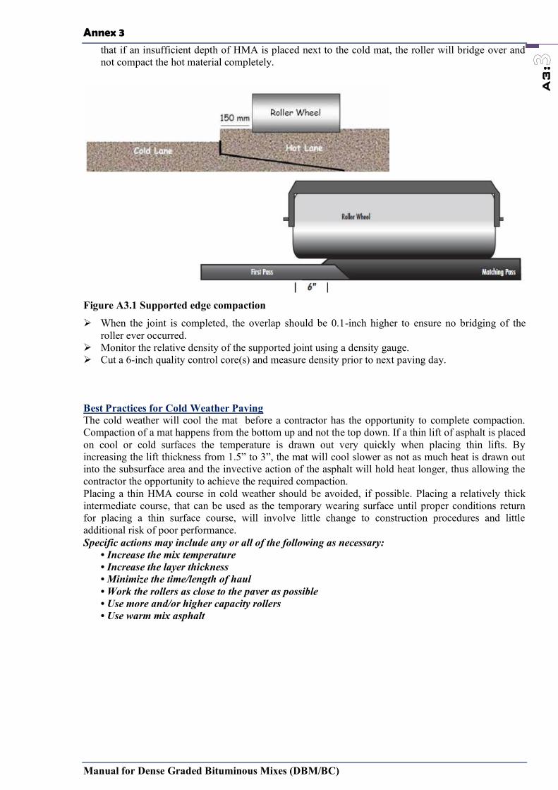
Annex 3
Manual for Dense Graded Bituminous Mixes (DBM/BC)
A3:
that if an insufficient depth of HMA is placed next to the cold mat, the roller will bridge over and not compact the hot material completely.
Figure A3.1 Supported edge compaction
When the joint is completed, the overlap should be 0.1-inch higher to ensure no bridging of the roller ever occurred.
Monitor the relative density of the supported joint using a density gauge. Cut a 6-inch quality control core(s) and measure density prior to next paving day.
Best Practices for Cold Weather Paving The cold weather will cool the mat before a contractor has the opportunity to complete compaction. Compaction of a mat happens from the bottom up and not the top down. If a thin lift of asphalt is placed on cool or cold surfaces the temperature is drawn out very quickly when placing thin lifts. By increasing the lift thickness from 1.5” to 3”, the mat will cool slower as not as much heat is drawn out into the subsurface area and the invective action of the asphalt will hold heat longer, thus allowing the contractor the opportunity to achieve the required compaction. Placing a thin HMA course in cold weather should be avoided, if possible. Placing a relatively thick intermediate course, that can be used as the temporary wearing surface until proper conditions return for placing a thin surface course, will involve little change to construction procedures and little additional risk of poor performance. Specific actions may include any or all of the following as necessary:
• Increase the mix temperature • Increase the layer thickness • Minimize the time/length of haul • Work the rollers as close to the paver as possible • Use more and/or higher capacity rollers • Use warm mix asphalt
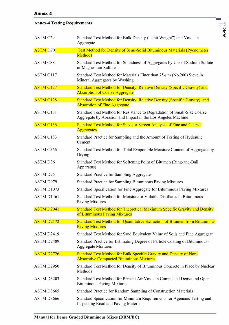
Annex 4
Manual for Dense Graded Bituminous Mixes (DBM/BC)
A4:
Annex-4 Testing Requirements
ASTM C29 Standard Test Method for Bulk Density (“Unit Weight”) and Voids in Aggregate
ASTM D70 Test Method for Density of Semi-Solid Bituminous Materials (Pycnometer Method)
ASTM C88 Standard Test Method for Soundness of Aggregates by Use of Sodium Sulfate or Magnesium Sulfate
ASTM C117 Standard Test Method for Materials Finer than 75-μm (No.200) Sieve in Mineral Aggregates by Washing
ASTM C127 Standard Test Method for Density, Relative Density (Specific Gravity) and Absorption of Coarse Aggregate
ASTM C128 Standard Test Method for Density, Relative Density (Specific Gravity), and Absorption of Fine Aggregate
ASTM C131 Standard Test Method for Resistance to Degradation of Small-Size Coarse Aggregate by Abrasion and Impact in the Los Angeles Machine
ASTM C136 Standard Test Method for Sieve or Screen Analysis of Fine and Coarse Aggregates
ASTM C183 Standard Practice for Sampling and the Amount of Testing of Hydraulic Cement
ASTM C566 Standard Test Method for Total Evaporable Moisture Content of Aggregate by Drying
ASTM D36 Standard Test Method for Softening Point of Bitumen (Ring-and-Ball Apparatus)
ASTM D75 Standard Practice for Sampling Aggregates
ASTM D979 Standard Practice for Sampling Bituminous Paving Mixtures
ASTM D1073 Standard Specification for Fine Aggregate for Bituminous Paving Mixtures
ASTM D1461 Standard Test Method for Moisture or Volatile Distillates in Bituminous Paving Mixtures
ASTM D2041 Standard Test Method for Theoretical Maximum Specific Gravity and Density of Bituminous Paving Mixtures
ASTM D2172 Standard Test Method for Quantitative Extraction of Bitumen from Bituminous Paving Mixtures
ASTM D2419 Standard Test Method for Sand Equivalent Value of Soils and Fine Aggregate
ASTM D2489 Standard Practice for Estimating Degree of Particle Coating of Bituminous-Aggregate Mixtures
ASTM D2726 Standard Test Method for Bulk Specific Gravity and Density of Non-Absorptive Compacted Bituminous Mixtures
ASTM D2950 Standard Test Method for Density of Bituminous Concrete in Place by Nuclear Methods
ASTM D3203 Standard Test Method for Percent Air Voids in Compacted Dense and Open Bituminous Paving Mixtures
ASTM D3665 Standard Practice for Random Sampling of Construction Materials
ASTM D3666 Standard Specification for Minimum Requirements for Agencies Testing and Inspecting Road and Paving Materials
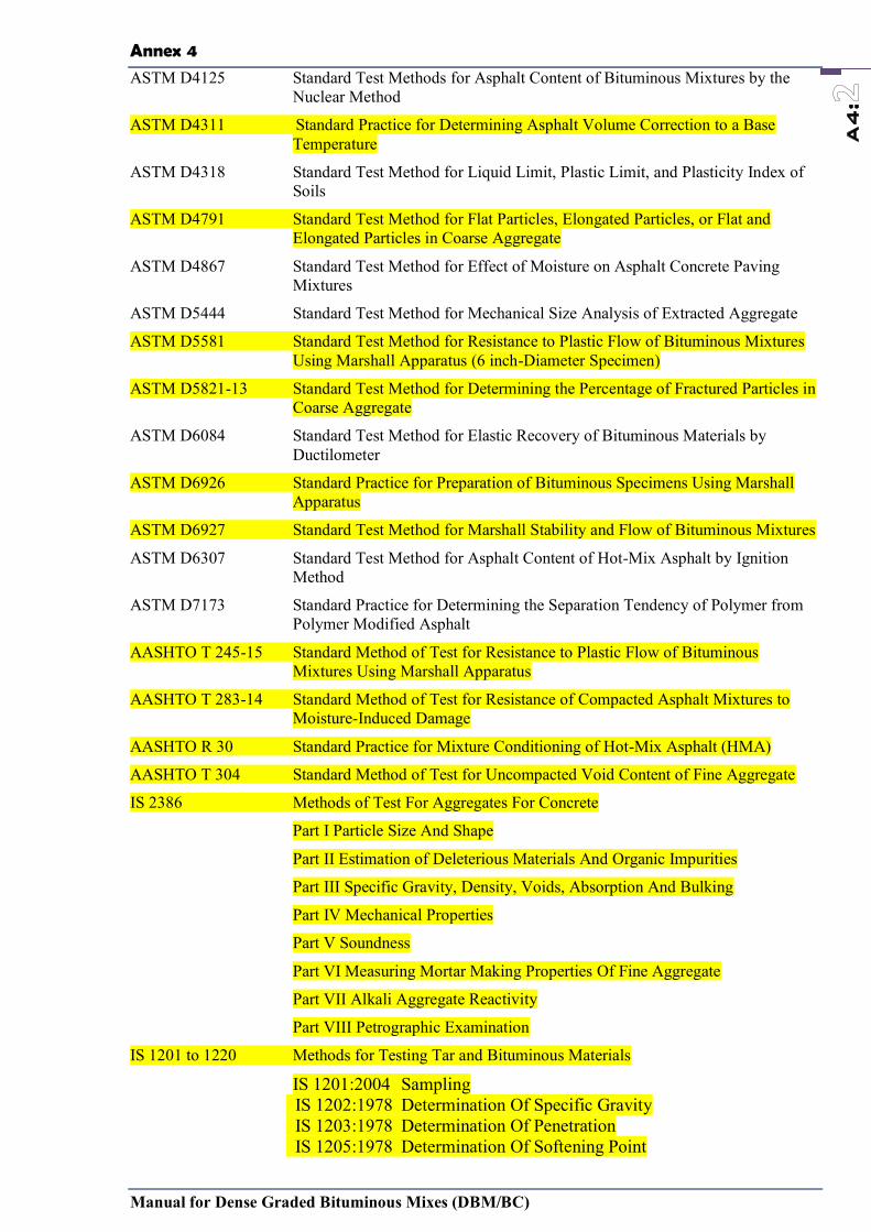
Annex 4
Manual for Dense Graded Bituminous Mixes (DBM/BC)
A4:
ASTM D4125 Standard Test Methods for Asphalt Content of Bituminous Mixtures by the Nuclear Method
ASTM D4311 Standard Practice for Determining Asphalt Volume Correction to a Base Temperature
ASTM D4318 Standard Test Method for Liquid Limit, Plastic Limit, and Plasticity Index of Soils
ASTM D4791 Standard Test Method for Flat Particles, Elongated Particles, or Flat and Elongated Particles in Coarse Aggregate
ASTM D4867 Standard Test Method for Effect of Moisture on Asphalt Concrete Paving Mixtures
ASTM D5444 Standard Test Method for Mechanical Size Analysis of Extracted Aggregate
ASTM D5581 Standard Test Method for Resistance to Plastic Flow of Bituminous Mixtures Using Marshall Apparatus (6 inch-Diameter Specimen)
ASTM D5821-13 Standard Test Method for Determining the Percentage of Fractured Particles in Coarse Aggregate
ASTM D6084 Standard Test Method for Elastic Recovery of Bituminous Materials by Ductilometer
ASTM D6926 Standard Practice for Preparation of Bituminous Specimens Using Marshall Apparatus
ASTM D6927 Standard Test Method for Marshall Stability and Flow of Bituminous Mixtures
ASTM D6307 Standard Test Method for Asphalt Content of Hot-Mix Asphalt by Ignition Method
ASTM D7173 Standard Practice for Determining the Separation Tendency of Polymer from Polymer Modified Asphalt
AASHTO T 245-15 Standard Method of Test for Resistance to Plastic Flow of Bituminous Mixtures Using Marshall Apparatus
AASHTO T 283-14 Standard Method of Test for Resistance of Compacted Asphalt Mixtures to Moisture-Induced Damage
AASHTO R 30 Standard Practice for Mixture Conditioning of Hot-Mix Asphalt (HMA)
AASHTO T 304 Standard Method of Test for Uncompacted Void Content of Fine Aggregate
IS 2386 Methods of Test For Aggregates For Concrete
Part I Particle Size And Shape
Part II Estimation of Deleterious Materials And Organic Impurities
Part III Specific Gravity, Density, Voids, Absorption And Bulking
Part IV Mechanical Properties
Part V Soundness
Part VI Measuring Mortar Making Properties Of Fine Aggregate
Part VII Alkali Aggregate Reactivity
Part VIII Petrographic Examination
IS 1201 to 1220 Methods for Testing Tar and Bituminous Materials
IS 1201:2004 Sampling IS 1202:1978 Determination Of Specific Gravity IS 1203:1978 Determination Of Penetration IS 1205:1978 Determination Of Softening Point
Annex 4
Manual for Dense Graded Bituminous Mixes (DBM/BC)
A4:
IS 1206 : Part 1:1978 Determination Of Viscosity: Part 2:1978 Determination Of Viscosity: Part 2 Absolute Viscosity , Part 3 Kinematic Viscosity IS 1208:1978 Determination Of Ductility IS 1209:1978 Determination Of Flash Point And Fire Point IS 1210:1978 Float Test IS 1212:1978 Determination Of Loss On Heating
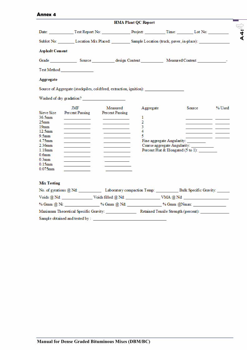
Annex 4
Manual for Dense Graded Bituminous Mixes (DBM/BC)
A4:

Annex 4
Manual for Dense Graded Bituminous Mixes (DBM/BC)
A4:
Annex 4
Manual for Dense Graded Bituminous Mixes (DBM/BC)
A4:
in Air in Water SSD in Air
Sheet ____ of____
Project Engineer: Send first 3 copies to Plant with cores
STANDARD DEVIATION
Original to QA folder
First carbon Project
Second carbon for Plant records
PAY FACTOR =
REMARKS:
PLANT CONTROL TECHNICIAN:
MAXIMUM GRAVITY
WEIGHT - GRAMS
VOLUME IN CC
BULK SPECIFIC GRAVITY
CORE LOT AYERAGE
HMA FIELD COMPACTION REPORT – CORE METHOD
Date Sampled:______________________ Contract No:__________________ F.A.P. No:______________ Plant Location: _________________________
Mix Design No:_______________________ Depth:________________________ Laid Over:_______________________ Cut By:___________________________
Lot Size: _________________________ Lot No: ___________________________ Mix Lot No:_________________ Mix Sublot No: _____________________
Witnessed By: ________________________________________________________ Tested By: _________________________________________________________
CORE SAMPLE NUMBER
DATE & TIME TONNAGE LAID
LOCATION THICKNESS%
DENSITY
SUBLOT AVERAGE %
DENSITYPWSL =
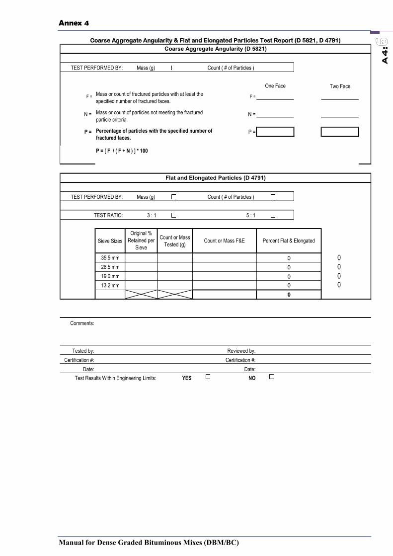
Annex 4
Manual for Dense Graded Bituminous Mixes (DBM/BC)
A4:
Coarse Aggregate Angularity & Flat and Elongated Particles Test Report (D 5821, D 4791)
Mass (g) Count ( # of Particles )
One Face Two Face
F = F =
N = N =
P = P =
P = [ F / ( F + N ) ] * 100
Mass (g) Count ( # of Particles )
3 : 1 5 : 1
Sieve SizesOriginal %
Retained per Sieve
Count or Mass Tested (g)
35.5 mm 026.5 mm 019.0 mm 013.2 mm 0
Comments:
Tested by: Reviewed by:Certification #: Certification #:
Date: Date:Test Results Within Engineering Limits: YES NO
Coarse Aggregate Angularity (D 5821)
Flat and Elongated Particles (D 4791)
TEST PERFORMED BY:
TEST RATIO:
TEST PERFORMED BY:
Mass or count of fractured particles with at least the specified number of fractured faces.
Mass or count of particles not meeting the fractured particle criteria.
Percentage of particles with the specified number of fractured faces.
00
Count or Mass F&E Percent Flat & Elongated
000
Annex 4
Manual for Dense Graded Bituminous Mixes (DBM/BC)
A4:
Sample ID: 1 2 3 4Pan & Dry Sample ( P&DS ):
Pan Tare ( Pan ):Oven Dry Sample ( A ): (P&DS - Pan)
Saturated Surface Dry Sample ( B ):Saturated Sample in Water ( C ):
Bulk Specific Gravity ( Gsb ): A/(B-C)
Bulk SSD Specific Gravity ( GsbSSD ): B/(B-C)
Apparent Specific Gravity ( Gsa ): A/(A-C)
Percent Absorption ( % Abs ): ((B-A)/A)*100
Specific Gravity and Absorption of Coarse Aggregate (T 85)
Test #:Mass of sample:
Mass of Cylinder + Glass + Crease (B):Mass of Water (C):
Temperature of Water, ˚F: Volume of Cylinder, mL (V):Bulk Specific Gravity ( Gsb):
Mass of Cylinder + sample (Wcs):Mass of empty Cylinder (Wc):
Mass of fine aggregate ( W ):
Average of % Uncompacted Voids (Uavg):
Temp˚F606570
73.4758085
Mass of Cylinder + Glass + Crease + Water (A):
997.32996.59
999.01
998.54997.97
995.83
Density kg/m3
T19 Table 3 - Density of Water
(190 g +/- 0.2 g)
(A - B)between 60 and 85˚F
1000*(C /density of water from table 3)(From T 84)
(Wcs - Wc)
% Uncompacted Voids (U): ((V - (W / Gsb)) / V) * 100
44 g57 g
Method A Sample Size
17 g190 g +/- 0.2 g
Sieve Size1.18 mm
997.54
600 µm300 µm150 µm
Uncompacted Void Content of Fine Aggregate - Method A (T 304)
Total Sample Mass:
Mass required
72 g

Annex 4
Manual for Dense Graded Bituminous Mixes (DBM/BC)
A4:
HMA Marshall Volumetric Properties Test Report (T 166, T 245)
Mass of Dry Specimen in Air (A): Mass of Specimen at SSD (B):
Mass of Specimen in Water (C):
Bulk Specific Gravity of Specimen (Gmb):
Theoretical Maximum Specific Gravity (Gmm):Percent Minus 75 µm of Sample (75 µm):
Percent PG Binder of Sample (Pb):Bulk Specific Gravity of Combined Aggregate (Gsb):
Specific Gravity of PG Binder (Gb): Average SpecificationPercent Voids in Mix (Pa): (100 * ((Gmm - Gmb) / Gmm))
Voids in the Mineral Agg. (VMA): (100-((Gmb * (100 - Pb)) / Gsb))
Voids Filled with Asphalt (VFA): ((100 * (VMA - Pa)) / VMA)Effective Agg. Specific Gravity (Gse): (100 - Pb)/((100/Gmm)-(Pb/Gb))
Percent Binder Absorbed: (Pba): (100 *((Gse - Gsb)/(Gsb*Gse))*Gb)Percent Binder Effective: (Pbe): (Pb - (( Pba / 100) * ( 100 - Pb)))
Fines to Effective Asphalt Ratio: ( 75 µm/ Pbe)
Number of Blows Each Side:Marshall Specimen Fabrication Temp.:
Maximum Load Dial Reading:Volume (V)/ Height Correction Factor (Vcf):
Uncorrected Stability (Su): AverageCorrected Stability (Sc):
Flow in 0.01 in.:
(From T 11)
( ºF )
Volumetric Analysis of Compacted HMA
Bulk Specific Gravity of Compacted HMA (T 166)
(A / ( B - C))(Gmb * 62.4)
Specimen Volume (V):
Specimen #:
( @ 77 +/- 1.8 ºF )(B-C)
Unit Weight, lb/ft3:
(Vcf*Su)
HMA Marshall Stability and Flow (T 245)
(From T 209)
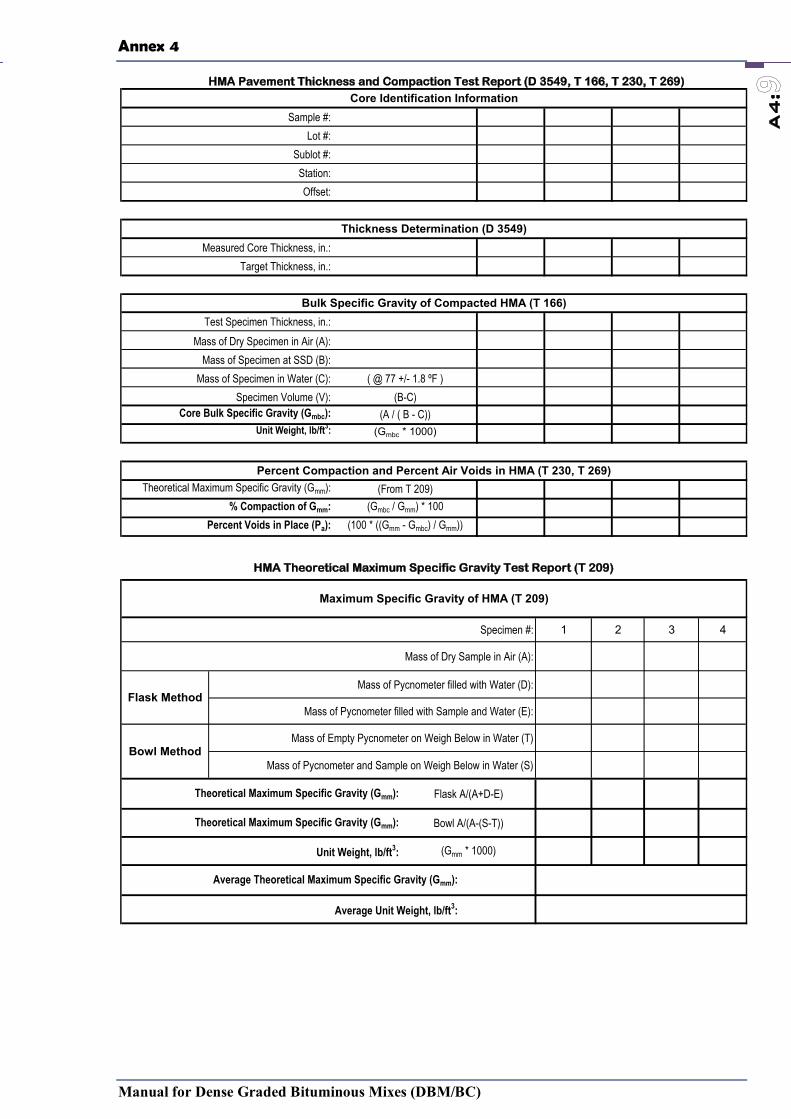
Annex 4
Manual for Dense Graded Bituminous Mixes (DBM/BC)
A4:
HMA Pavement Thickness and Compaction Test Report (D 3549, T 166, T 230, T 269)
Sample #:Lot #:
Sublot #:Station:Offset:
Measured Core Thickness, in.:Target Thickness, in.:
Test Specimen Thickness, in.:Mass of Dry Specimen in Air (A):
Mass of Specimen at SSD (B):Mass of Specimen in Water (C): ( @ 77 +/- 1.8 ºF )
Specimen Volume (V): (B-C)Core Bulk Specific Gravity (Gmbc): (A / ( B - C))
Unit Weight, lb/ft3: (Gmbc * 1000)
Theoretical Maximum Specific Gravity (Gmm): (From T 209) % Compaction of Gmm: (Gmbc / Gmm) * 100
Percent Voids in Place (Pa): (100 * ((Gmm - Gmbc) / Gmm))
Core Identification Information
Thickness Determination (D 3549)
Bulk Specific Gravity of Compacted HMA (T 166)
Percent Compaction and Percent Air Voids in HMA (T 230, T 269)
HMA Theoretical Maximum Specific Gravity Test Report (T 209)
Specimen #: 1 2 3 4
Mass of Dry Sample in Air (A):
Mass of Pycnometer filled with Water (D):
Mass of Pycnometer filled with Sample and Water (E):
Mass of Empty Pycnometer on Weigh Below in Water (T)
Mass of Pycnometer and Sample on Weigh Below in Water (S)
Theoretical Maximum Specific Gravity (Gmm): Flask A/(A+D-E)
Theoretical Maximum Specific Gravity (Gmm): Bowl A/(A-(S-T))
Unit Weight, lb/ft3: (Gmm * 1000)
Average Theoretical Maximum Specific Gravity (Gmm):
Average Unit Weight, lb/ft3:
Bowl Method
Maximum Specific Gravity of HMA (T 209)
Flask Method

Annex 4
Manual for Dense Graded Bituminous Mixes (DBM/BC)
A4:
Specimen #:Sand Reading, in. (A):Clay Reading, in. (B):
Sand Equivalent (SE): (( A / B) * 100)
Average Sand Equivalent (SE):
Note:
Plastic Fines in Graded Aggregates by Sand Equivalent Test (T 176)
All values are rounded to the next higher integer value if the measured or calculated results have a decimal portion.
Annex -5
Name of Project :Contract Id : Date of Inspection :Name of Inspecting Official :
Yes No Comments
1. Have approved QAP2. Material Source / Material Verified
AggregateSandStone DustButimen
3. Have Mix Design ReportNMAS selected comply the Table 2.2 Mix design based on Marshal Method for NMAS <25mmMix design based on Modified Marshal Method for NMAS >25mm
Mix Proportion mentioned in reportMixing Temperature mentionedCompaction Temperature mentionedButimen Content mentioned
4. Have daily detail work schedule5. Have Traffic Management Plan6. Paving Equipment
PaverHopper clean of all foreign (non-HMA) materialScreed vibration functionalScreed heaters functionalEquipped with automatic slope and grade control (contact ski orsonic)Equipped with proper lighting if night paving
RollerSprinkler system in uniform working orderDrum scrapers in good conditionVibratory roller equipped with indicators that display amplitude,frequency and speed settings/readouts to measure impacts per footOscillatory roller equipped with frequency indicators
Haul TrucksNo rips or tears in tarpNo mesh tarps allowedTruck bed and tires clean of all foreign material (non-HMA)
7. Production PlantPlant is calibratedPlant trial has been doneAggregate stockpiles are covered Defect free Scalping Screens Mixing Temperature as per recommendationCompaction Temperature as per recommendationButimen Content as per mix design
1. Weather
Checklist for Inspection
BEFORE PAVING
DURING PAVING

Yes No CommentsAre weather conditions (temperature, rain, surface moisture, etc.)suitable for paving? Will they remain that way throughout the paving operation?No HMA is to be placed when air or base temperatures are below5°C.
Surface ConditionsAre utility structures set properly?If paving on base, is it non-segregated, uniformly compacted andfree of standing water?If paving on Portland/bituminous concrete or milled surface, is the
surface clean, swept and have an application of tack coat if required
(review specification)? If paving on a milled surface, see additional
requirements in the Milling Inspection section below.
The Contractor is required to supply a 3m straightedge for theinspectors use (pavement smoothness and transverse constructionjoint transitions).All surfaces in contact with HMA that have been in place for longer
than 3 calendar days must have an application of tack coat. The
tack coat must be applied at the specified application rate uniformly
using a non-gravity pressurized overlapping spray. The paver’s screed should be placed on starting blocks, allowingfor an additional ¼ inch per inch of desired compacted thickness.Adjust as necessary, use Contractor supplied 3m straightedge tocheck the joint.Automatic slope and grade controls must be used.Delivery trucks should have their tarps down and securely fastened,lifted just before unloading.Verify trucks are within legal load limits, or have permit foroverweight loads.Check to verify that HMA material loaded in a manner to uniformlydistribute into the truck bed.Do not allow trucks to bump the paver when unloading.Lift truck bed such that the material moves as one mass into thehopper to prevent segregation.Take initial temperature of material in each truck at time ofunloading using a calibrated stick type thermometer or infraredgun. If using an infrared gun and temperature is outside ofspecification, the temperature must be verified using a stick typethermometer before rejection.Keep paver hopper at least ½ full at all times to preventsegregation.Verify that the screed pre-heaters are used.Verify that the screed vibration is being used throughout the pavingoperation.Paver’s augers should turn slow and consistently, not quick starts
and stops. Keep a constant head of material in the auger chamber,
only the top half of the auger flights should be exposed. Match the paver’s speed to material and truck supply to minimizeor eliminate paver stops due to material supply.Maximum paver speed 12m/min.Keep the longitudinal joint straight.Take frequent depth checks.It is recommended that a minimum of 4 yield checks be made perDensity Lot.
2. Paving Operation
Yes No CommentsLongitudinal joints of the lift being placed should be offset 6-12inches from the longitudinal joint directly below it.When matching an existing lift or course of material longitudinally,
overlap the joint approximately ½ to 1 inch. Do not allow the lute
person to broadcast material from the joint onto the newly placed
mat. Luting should be kept to a minimum, if at all. Avoid excess or
unnecessary hand spreading or luting.When using the Notched Wedge Joint method for the longitudinaljoint, the methods and equipment must first be approved by theEngineerRefueling of paving equipment in the paving area is not allowed.
Check mat consistently for fat spots (deposits of bitumen and fine
aggregates from paving equipment), segregation, flushing (liquid
bitumen rising to the surface during compaction), cracking or any
other non-uniformity with corrections made when necessary.Check the mat for pavement smoothness with the Contractor
supplied 3m straightedge. The surface course shall not vary by
more than ¼ inch. For all other courses it shall be ⅜ inch.Temporary transverse construction joint lengths shall be
constructed as specified. When paving is to continue, the joint shall
be formed by saw-cutting a sufficient distance back from the
previous run exposing the full depth of the lift or course.
The Contractor shall use an adequate number and size of rollers(with equal number of operators) to match the paving operation andachieve specified in-place density. Number and size of rollersshould match what is listed in the QCP.Immediately establish a rolling pattern that consistently achievesspecified in-place density. The pattern may need to be adjustedduring the operation due to changing temperatures and pavingconditions.Rollers should not roll too fast. Normally, a static roller’smaximum speed is 5 m.p.h. and a vibratory roller’s maximumspeed is 2 ½ m.p.h. Rolling should begin at the side or low point, moving towards thecenter of the mat. If a longitudinal joint is formed, then roll the jointfirst.For steep grades, it is recommended to vibrate uphill and static rolldownhill.Contractor shall use necessary hand tools for compaction aroundcatch-basins, manholes and other structures.
In-place density testing shall be performed as specified.Daily mix verification
Roadway SamplingTruck Sampling
Bitumen content verification Aggregate gradation verificationMaximum specific gravity of the mix verificationBulk specific gravity and Air Voids of the mix verificationStability (Marshall) and flow (Marshall) verification
4. Quality Testing (QC/QA)
3. Rolling Operation and Compaction

Yes No Comments
The Contractor shall extract the cores (wet sawed) from sampling
locations determined by the Engineer. The Contractor must not be
given the core locations in advance of cutting (prior to the
completion of finish rolling) to ensure the testing is truly random.
If the Contractor disputes the Engineer’s test results, they mustsubmit in writing a request to initiate the process within 7 calendardays of the notification of the test results.If authorized, the Contractor must extract four core samples per
disputed Density Lot no later than 14 calendar days from
authorization using the stratified random sampling procedure.
5. Density Acceptance Testing Utilizing Cores
6. Density Dispute Resolution Process