DEPARTMENT OF MECHANICAL ENGINEERING - · PDF file · 2015-06-17measurement of flow...
51
MECHANICS OF FLUIDS AND HYDRAULIC MACHNIES educateindiaprashanth.wordpress.com M PRASHANTH REDDY [email protected] RAM PRASHANTH REDDY MAMIDIPALLI DEPARTMENT OF MECHANICAL ENGINEERING MECHANICS OF FLUIDS AND HYDRAULIC MACHINES LAB PRASHANTH REDDY M [Type the company name]
Transcript of DEPARTMENT OF MECHANICAL ENGINEERING - · PDF file · 2015-06-17measurement of flow...

MECHANICS OF FLUIDS AND HYDRAULIC MACHNIES educateindiaprashanth.wordpress.com
M PRASHANTH REDDY [email protected] RAM PRASHANTH REDDY MAMIDIPALLI
DEPARTMENT
OF
MECHANICAL ENGINEERING
MECHANICS OF FLUIDS AND HYDRAULIC MACHINES LAB
PRASHANTH REDDY M
[Type the company name]

MECHANICS OF FLUIDS AND HYDRAULIC MACHNIES educateindiaprashanth.wordpress.com
M PRASHANTH REDDY [email protected] RAM PRASHANTH REDDY MAMIDIPALLI
LIST OF EXPERIMENTS
S.NO. NAME OF EXPERIMENT PAGE
NO. DATE REMARK SIGN
1 IMPACT OF JETS ON VANES
(flat, curved ,semi sphere)
2 CALIBRATION OF VENTURIMETER
3 CALIBRATION OF ORIFICEMETER
4 FRICTION FACTOR
5 VERIFICATION OF BERNOULIS
THEOREM
6 CENTRIFUGAL PUMP
7 RECIPROCATING PUMP TEST RIG
8 FRANCIS TURBINE
9 PELTON WHEEL TURBINE
10 KAPLAN TURBINE
11 MULTI STAGE CENTRIFUGAL
PUMP
12

MECHANICS OF FLUIDS AND HYDRAULIC MACHNIES educateindiaprashanth.wordpress.com
M PRASHANTH REDDY [email protected] RAM PRASHANTH REDDY MAMIDIPALLI
IMPACT OF JETS ON VANES
AIM:
To determine the Co-efficient of Impact for vanes.
APPARATUS:
Impact of Jet experimental Set up, stop watch & Vane of different shape (flat and
curved)
DESCRIPTION:
Momentum equation is based on Newton’s second law of motion which states that
the algebraic sum of external forces applied to control volume of fluid in any direction is
equal to the rate of change of momentum in that direction. The external forces include the
component of the weight of the fluid & of the forces exerted externally upon the
boundary surface of the control volume. If a vertical water jet moving with velocity is
made to strike a target, which is free to move in the vertical direction then a force will be
exerted on the target by the impact of jet, according to momentum equation this force
(which is also equal to the force required to bring back the target in its original position)
must be equal to the rate of change of momentum of the jet flow in that direction.
PROCEDURE:
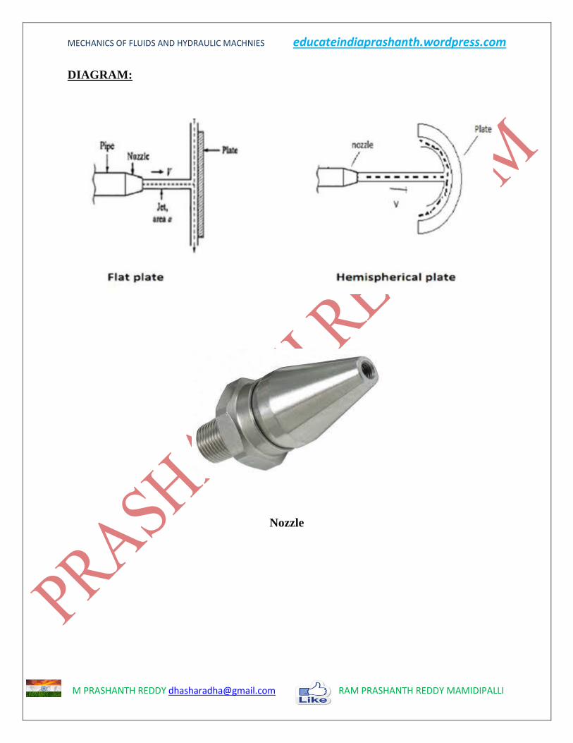
1. Fix a required vane (suppose a Flat Plate) to the lever.
2. Adjust the Balancing Weight so that the lever becomes horizontal.
3. Add Known weight to the pan attached to one end of the lever. This will disturb
the initial balance of the lever.
4. Start the supply. The jet of water through the nozzle will impinge on the vane. The
force due to impact of water will be acting on the vane in the upward direction.
5. Adjust the Supply valve so that the lever will be back to its initial balance.
6. Adjust the weights in the pan and take few more readings.
7. With different vanes attached, and weights, repeat the procedure.
MECHANICS OF FLUIDS AND HYDRAULIC MACHNIES educateindiaprashanth.wordpress.com
M PRASHANTH REDDY [email protected] RAM PRASHANTH REDDY MAMIDIPALLI
DIAGRAM:
Nozzle

MECHANICS OF FLUIDS AND HYDRAULIC MACHNIES educateindiaprashanth.wordpress.com
M PRASHANTH REDDY [email protected] RAM PRASHANTH REDDY MAMIDIPALLI
TABULAR COLUMS:
S.NO Fa
(Actual
Force in Kg)
Ft
(Theoretical
force in Kg)
t
(Time taken for
h cm raise of
water in tank)
Q= 𝑨×𝒉
𝒕 K = Fa/Ft
(coefficient of
Impact)

MECHANICS OF FLUIDS AND HYDRAULIC MACHNIES educateindiaprashanth.wordpress.com
M PRASHANTH REDDY [email protected] RAM PRASHANTH REDDY MAMIDIPALLI
CALCULATIONS:
Ft= ρav2(1+cos φ)
Fa= Load added to the pan
ρ= density of the water=1000 kg/m3
A= area of nozzle
V= velocity of jet in m/sec
φ= angle made by the jet after impact (0˚ for flat wane and 135˚ for curved wane)
Q= discharge of water m3/sec
Q= [Volume of tank / Time taken for h cm raise of water in tank]
= [Area of Tank × h]/t m3/sec
Area of tank=50×50 cm2
Q=area of nozzle × velocity of jet = a×v m3/sec
K = 𝐹𝑎
𝐹𝑡
Dia of nozzle = 1 cm
RESULT:
PRECAUTIONS:

MECHANICS OF FLUIDS AND HYDRAULIC MACHNIES educateindiaprashanth.wordpress.com
M PRASHANTH REDDY [email protected] RAM PRASHANTH REDDY MAMIDIPALLI
CLAIBRATION OF VENTURIMETER
AIM:
To determine the coefficient of discharge of venturi meter.
APPARATUS:
A pipe provided with inlet and outlet and pressure tapping and venturi in between
them, Differential u-tube manometer, Collecting tank with piezometer, Stopwatch,
Scale
THEORY:
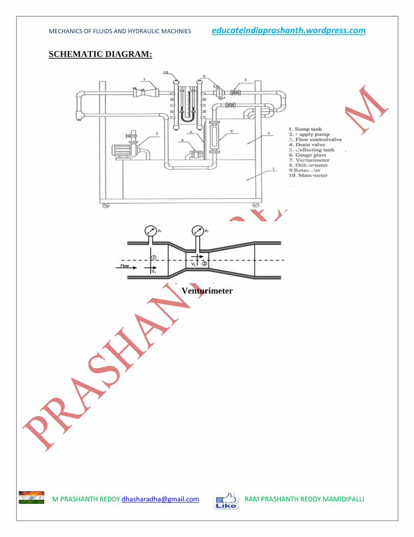
Venturi, the Italian engineer, discovered in 1791 that a pressure difference related
the rate of flow could be created in pipe by deliberately reducing its area of cross-section.
The modern version of the venturi meter was first developed and employed for
measurement of flow of water by Clemens Herschel in 1886. Venturi meter continues to
be the best and most precise instrument for measurement of all types of fluid flow in
pipes. The meter consists of a short length of gradual convergence throat and a longer
length of gradual divergence. The semi-angle of convergence is 8 to 10 degrees and the
semi-angle of divergenceis3 to 5 degrees. By measuring the difference in fluid pressure
becore and after throt the flow rate can be obtained from Bernoulli's equation.
PROCEDURE:
1. The pipe is selected for doing experiments
2. The motor is switched on, as a result water will flow
3. According to the flow, the ccl4 level fluctuates in the U-tube manometer
4. The reading of H1 and H2 are noted
5. The time taken for 5 cm rise of water in the collecting tank is noted
6. The experiment is repeated for various flow in the same pipe
7. The co-efficient of discharge is calculated
MECHANICS OF FLUIDS AND HYDRAULIC MACHNIES educateindiaprashanth.wordpress.com
M PRASHANTH REDDY [email protected] RAM PRASHANTH REDDY MAMIDIPALLI
SCHEMATIC DIAGRAM:
Venturimeter

MECHANICS OF FLUIDS AND HYDRAULIC MACHNIES educateindiaprashanth.wordpress.com
M PRASHANTH REDDY [email protected] RAM PRASHANTH REDDY MAMIDIPALLI
TABULARCOLUMN:
S.NO Manometric head Time taken for h
cm raise of water
in tank t
Theoretical
Discharge
(Qt) m3/sec
Actual
Discharge
(Qa) m3/sec
Coefficient of
discharge
Cd = Qa/Qt h1 h2 hw
MECHANICS OF FLUIDS AND HYDRAULIC MACHNIES educateindiaprashanth.wordpress.com
M PRASHANTH REDDY [email protected] RAM PRASHANTH REDDY MAMIDIPALLI
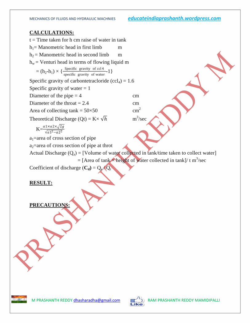
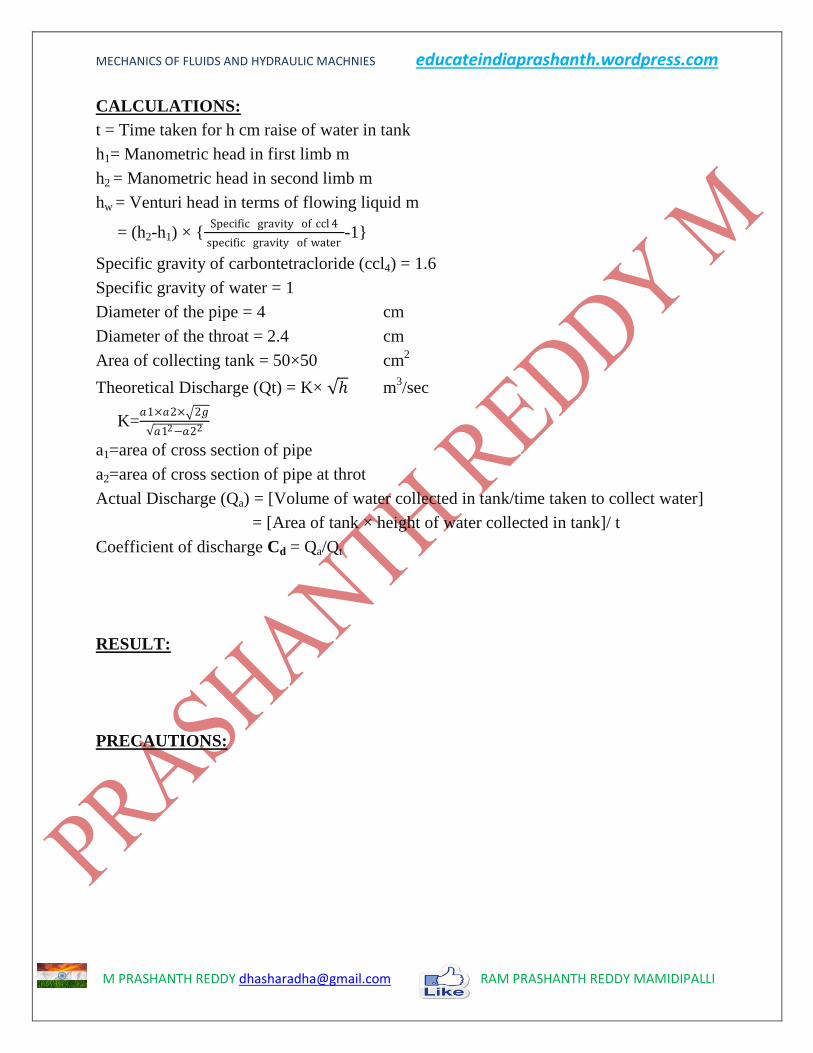
CALCULATIONS:
t = Time taken for h cm raise of water in tank
h1= Manometric head in first limb m
h2 = Manometric head in second limb m
hw = Venturi head in terms of flowing liquid m
= (h2-h1) × {Specific gravity of ccl 4
specific gravity of water-1}
Specific gravity of carbontetracloride (ccl4) = 1.6
Specific gravity of water = 1
Diameter of the pipe = 4 cm
Diameter of the throat = 2.4 cm
Area of collecting tank = 50×50 cm2
Theoretical Discharge (Qt) = K× ℎ m3/sec
K=𝑎1×𝑎2× 2𝑔
𝑎12−𝑎22
a1=area of cross section of pipe
a2=area of cross section of pipe at throt
Actual Discharge (Qa) = [Volume of water collected in tank/time taken to collect water]
= [Area of tank × height of water collected in tank]/ t m3/sec
Coefficient of discharge (Cd) = Qa / Qt
RESULT:
PRECAUTIONS:

MECHANICS OF FLUIDS AND HYDRAULIC MACHNIES educateindiaprashanth.wordpress.com
M PRASHANTH REDDY [email protected] RAM PRASHANTH REDDY MAMIDIPALLI
CLAIBRATION OF ORIFICEMETER
AIM:
To determine the coefficient of discharge of orifice meter.
APPARATUS:
A pipe provided with inlet and outlet and pressure tapping and Orifice in between
them, Differential U-tube manometer, Collecting tank with piezometer, Stopwatch, Scale
THEORY:
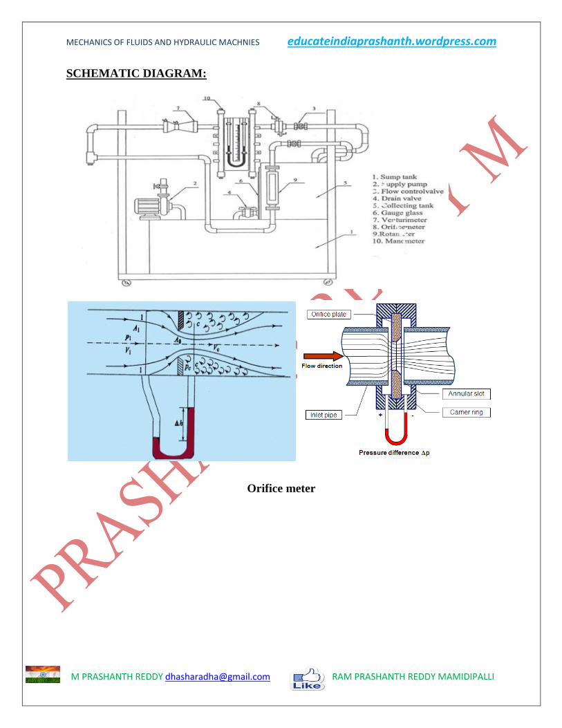
An orifice plate is a thin plate with a hole in it, which is usually placed in a pipe.
When a fluid passes through the orifice, its pressure builds up slightly upstream of the
orifice, but as the fluid is forced to converge to pass through the hole, the velocity
increases and the fluid pressure decreases. A little downstream of the orifice the flow
reaches its point of maximum convergence, afterd that, the flow expands, the velocity
falls and the pressure increases. By measuring the difference in fluid pressure across
tappings upstream and downstream of the plate, the flow rate can be obtained from
Bernoulli's equation.
PROCEDURE:
1. The pipe is selected for doing experiments
2. The motor is switched on, as a result water will flow
3. According to the flow, the ccl4 level fluctuates in the U-tube manometer
4. The reading of H1 and H2 are noted
5. The time taken for 5cm rise of water in the collecting tank is noted
6. The experiment is repeated for various flow in the same pipe
7. The co-efficient of discharge is calculated
MECHANICS OF FLUIDS AND HYDRAULIC MACHNIES educateindiaprashanth.wordpress.com
M PRASHANTH REDDY [email protected] RAM PRASHANTH REDDY MAMIDIPALLI
SCHEMATIC DIAGRAM:
Orifice meter

MECHANICS OF FLUIDS AND HYDRAULIC MACHNIES educateindiaprashanth.wordpress.com
M PRASHANTH REDDY [email protected] RAM PRASHANTH REDDY MAMIDIPALLI
TABULARCOLUMN:
S.NO Manometric head Time taken for h
cm raise of water
in tank t
Theoretical
Discharge
(Qt) m3/sec
Actual
Discharge
(Qa) m3/sec
Coefficient of
discharge
Cd = Qa/Qt h1 h2 hw
MECHANICS OF FLUIDS AND HYDRAULIC MACHNIES educateindiaprashanth.wordpress.com
M PRASHANTH REDDY [email protected] RAM PRASHANTH REDDY MAMIDIPALLI
CALCULATIONS:
t = Time taken for h cm raise of water in tank
h1= Manometric head in first limb m
h2 = Manometric head in second limb m
hw = Venturi head in terms of flowing liquid m
= (h2-h1) × {Specific gravity of ccl 4
specific gravity of water-1}
Specific gravity of carbontetracloride (ccl4) = 1.6
Specific gravity of water = 1
Diameter of the pipe = 4 cm
Diameter of the throat = 2.4 cm
Area of collecting tank = 50×50 cm2
Theoretical Discharge (Qt) = K× ℎ m3/sec
K=𝑎1×𝑎2× 2𝑔
𝑎12−𝑎22
a1=area of cross section of pipe
a2=area of cross section of pipe at throt
Actual Discharge (Qa) = [Volume of water collected in tank/time taken to collect water]
= [Area of tank × height of water collected in tank]/ t
Coefficient of discharge Cd = Qa/Qt
RESULT:
PRECAUTIONS:
MECHANICS OF FLUIDS AND HYDRAULIC MACHNIES educateindiaprashanth.wordpress.com
M PRASHANTH REDDY [email protected] RAM PRASHANTH REDDY MAMIDIPALLI
FRICTION FACTOR
AIM:
To determine the Darcy's friction factor (f) of the given pipe
APPARATUS:
A pipe provided with inlet and outlet and pressure tapping, Differential u-tube
manometer, collecting tank with piezometer, Stopwatch, Scale.
DESCRIPTION:
When the fluid flows through a pipe the viscosity of the fluid and the inner surface
of the pipe offer resistance to the flow. In overcoming the resistance some energy of the
flowing fluid is lost. This is called the major loss in pipe flow. Boundary roughness,
which has little significance in laminar flow, plays an important role in turbulence. This,
together with transverse momentum exchange of fluid particles due to the perpetual
turbulent intermixing, are the main sources of tangential or shear stresses in turbulent
flow. Various equations have been proposed to determine the head losses due to friction.
These equations relate the friction losses to physical characteristics of the pipe and
various flow parameters.
PROCEDURE:
1. The pipe is selected for doing experiments
2. The motor is switched on, as a result water will flow
3. According to the flow, the mercury level fluctuates in the U-tube manometer
4. The reading of H1 and H2 are noted
5. The time taken for 5cm rise of water in the collecting tank is noted
6. The experiment is repeated for various flow in the same pipe
7. The co-efficient of discharge is calculated

MECHANICS OF FLUIDS AND HYDRAULIC MACHNIES educateindiaprashanth.wordpress.com
M PRASHANTH REDDY [email protected] RAM PRASHANTH REDDY MAMIDIPALLI
SCHEMATIC DIAGRAM:

MECHANICS OF FLUIDS AND HYDRAULIC MACHNIES educateindiaprashanth.wordpress.com
M PRASHANTH REDDY [email protected] RAM PRASHANTH REDDY MAMIDIPALLI
TABULARCOLUMN:
S.NO Manometric head Time taken for h
cm raise of water
in tank t sec
Discharge
(Q)
m3/sec
Velocity
(v) m/sec
Friction
factor (f) h1 h2 hf

MECHANICS OF FLUIDS AND HYDRAULIC MACHNIES educateindiaprashanth.wordpress.com
M PRASHANTH REDDY [email protected] RAM PRASHANTH REDDY MAMIDIPALLI
CALCULATIONS:
Friction factor (f) = 2 x g x D x hf
l x v2 Where,
g = Acceleration due to gravity (m / sec2)
D for circular pipe =4x𝑐𝑟𝑜𝑠𝑠 𝑠𝑒𝑐𝑡𝑖𝑜𝑛𝑎𝑙 𝑎𝑟𝑒𝑎
𝑤𝑒𝑡𝑡𝑒𝑑 𝑝𝑒𝑟𝑖𝑚𝑒𝑡𝑒𝑟 =4x
𝜋𝑟2
𝜋𝑑=d
d= Diameter of the pipe = 2cm
D for squarer pipe = 4x𝑐𝑟𝑜𝑠𝑠 𝑠𝑒𝑐𝑡𝑖𝑜𝑛𝑎𝑙 𝑎𝑟𝑒𝑎
𝑤𝑒𝑡𝑡𝑒𝑑 𝑝𝑒𝑟𝑖𝑚𝑒𝑡𝑒𝑟=4x
𝑤xh
2x w+h
w= width of pipe, h= height of pipe
l = Length of the pipe = 200cm
v = Velocity of liquid following in the pipe (m / s)
hf = Loss of head due to friction (m)
= (h2-h1) × { Specific gravity of Hg
specific gravity of water - 1} Where
h1 = Manometric head in the first limbs
h2 = Manometric head in the second limbs
Actual Discharge Q = A x h
t (m
3 / sec)
Where
A = Area of the collecting tank (m2)
h = Rise of water for 5 cm (m)
t = Time taken for 5 cm rise (sec)
Also
Q=Velocity in the pipe X Area of the pipe
= v x a
v= Q/a
RESULT:
PRECAUTIONS:

MECHANICS OF FLUIDS AND HYDRAULIC MACHNIES educateindiaprashanth.wordpress.com
M PRASHANTH REDDY [email protected] RAM PRASHANTH REDDY MAMIDIPALLI
VERIFICATION OF BERNOULIS THEOREM
AIM:
To verify the Bernoulli’s theorem.
APPARATUS:
A supply tank of water, a tapered inclined pipe fitted with no. of piezometer tubes
point, measuring tank, scale, and stop watch.
THEORY:
Bernoulli’s theorem states that when there is a continues connection between the
particle of flowing mass liquid, the total energy of any sector of flow will remain same
provided there is no reduction or addition at any point. I.e. sum of pressure head and
velocity head is constant.
PROCEDURE:
1. Open the inlet valve slowly and allow the water to flow from the supply tank.
2. Now adjust the flow to get a constant head in the supply tank to make flow in and
outflow equal.
3. Under this condition the pressure head will become constant in the piezometer
tubes. Note down piezometer readings.
4. Note down the quantity of water collected in the measuring tank for a given
interval of time.
5. Compute the area of cross-section under the piezometer tube.
6. Compute the values of velocity head and pressure head.
7. Change the inlet and outlet supply and note the reading.
8. Take at least three readings as described in the above steps.

MECHANICS OF FLUIDS AND HYDRAULIC MACHNIES educateindiaprashanth.wordpress.com
M PRASHANTH REDDY [email protected] RAM PRASHANTH REDDY MAMIDIPALLI
SCHEMATIC DIAGRAM:
Throt

MECHANICS OF FLUIDS AND HYDRAULIC MACHNIES educateindiaprashanth.wordpress.com
M PRASHANTH REDDY [email protected] RAM PRASHANTH REDDY MAMIDIPALLI
TABULARCOLUMN:
S.NO Pizeometer
Reading
time for
5cm rise
Discharge
Q m3/sec
Pressure
Head m
Velocity
Head m
Datum
head m
Total Head
S.NO Pizeometer
Reading
time for
5cm rise
Discharge
Q m3/sec
Pressure
Head m
Velocity
Head m
Datum
head m
Total Head
S.NO Pizeometer
Reading
time for
5cm rise
Discharge
Q m3/sec
Pressure
Head m
Velocity
Head m
Datum
head m
Total Head

MECHANICS OF FLUIDS AND HYDRAULIC MACHNIES educateindiaprashanth.wordpress.com
M PRASHANTH REDDY [email protected] RAM PRASHANTH REDDY MAMIDIPALLI
CALCULATIONS:
Pressure head = P
ρg m
Velocity head = v2
2g m
Datum head = Z = 0 m (for this experiment)
Velocity of water flow = v
Q (Discharge) = [Volume of water collected in tank/time taken to collect water]
= [Area of tank × height of water collected in tank]/ t m3/sec
Also
Q= velocity of water in pipe × area of cross section = v × Ax m3/sec
Area of cross section (Ax) = At + [(Ai−At)×Ln
L] m
2
At = Area of Throt
Ai = Area of Inlet
Dia of throt = 25mm
Dia of inlet = 50mm
Ln= distance between throt and corresponding pizeometer
L=length of the diverging duct or converging duct = 300mm
Distance between each piezometer = 75mm
Total Head = 𝑃
ρg +
v2
2g + Z
RESULT:
PRECAUTIONS:

MECHANICS OF FLUIDS AND HYDRAULIC MACHNIES educateindiaprashanth.wordpress.com
M PRASHANTH REDDY [email protected] RAM PRASHANTH REDDY MAMIDIPALLI
CENTRIFUGAL PUMP
AIM:
To study the performance characteristics of a centrifugal pump
APPARATUS:
1. centrifugal pump test setup
2. stop watch
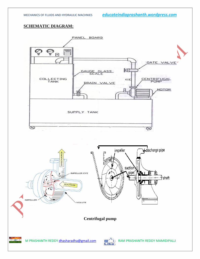
DESCRIPTION:
The operation of filling water in the suction pipe casing and a portion delivery pipe for
the removal of air before starting is called priming.
After priming the impeller is rotated by a prime mover. The rotating vane gives a
centrifugal head to the pump. When the pump attains a constant speed, the delivery valve
is gradually opened. The water flows in a radially outward direction. Then, it leaves the
vanes at the outer circumference with a high velocity and pressure. Now kinetic energy is
gradually converted in to pressure energy. The high-pressure water is through the
delivery pipe to the required height.
PROCEDURE:
1) Prime the pump, close the delivery valve and switch on the unit.
2) Open the delivery valve and maintain required head. Note the reading of pressure
gauge.
3) Note the corresponding reading from vacuum gauge.
4) Measure the area of the collecting tank
5) Close the drain valve and note the time for 10 cm rise of water level in the collecting
tank.
6) For different delivery head repeat the experiment.
7) For every set of reading note the time taken for 3 rev. Energy meter.
MECHANICS OF FLUIDS AND HYDRAULIC MACHNIES educateindiaprashanth.wordpress.com
M PRASHANTH REDDY [email protected] RAM PRASHANTH REDDY MAMIDIPALLI
SCHEMATIC DIAGRAM:
Centrifugal pump
MECHANICS OF FLUIDS AND HYDRAULIC MACHNIES educateindiaprashanth.wordpress.com
M PRASHANTH REDDY [email protected] RAM PRASHANTH REDDY MAMIDIPALLI
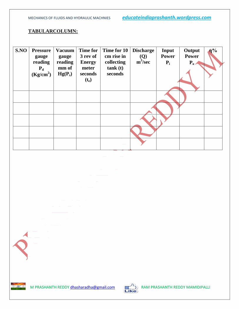
TABULARCOLUMN:
S.NO Pressure
gauge
reading
Pd
(Kg/cm2)
Vacuum
gauge
reading
mm of
Hg(Ps)
Time for
3 rev of
Energy
meter
seconds
(te)
Time for 10
cm rise in
collecting
tank (t)
seconds
Discharge
(Q)
m3/sec
Input
Power
Pi
Output
Power
Po
η%

MECHANICS OF FLUIDS AND HYDRAULIC MACHNIES educateindiaprashanth.wordpress.com
M PRASHANTH REDDY [email protected] RAM PRASHANTH REDDY MAMIDIPALLI
CALCULATIONS:
1. The total effective head H in meters of water column = Hd + Hs + Z
* since the delivery pressure is in Kg/cm2 and suction gauge readings are in mm
of Hg, the total head developed by the pump to be converted in meters of water
column.
Where Hd = delivery head = Pd/ρ kg/cm2
Hs = suction head= 𝑃𝑠×13600
𝜌 mm of Hg
Z= datum level difference = 2.8 m
Note: the velocity head and the loss of the head in the suction pipe are neglected.
2. Knowing the discharge Q = 𝑨×𝒉
𝒕 m
3/sec.
Where
A = Area of the collecting tank (m2) = 70 X 70 cm
2
h = 10 cm rise of water level in the collecting tank
t = Time taken for 10 cm rise of water level in collecting tank.
2. The work done by the pump is given by Po = ρ × g × Q × H
1000 Kw
Where,
ρ = Density of water = 1000 (kg / m³)
g = Acceleration due to gravity = 9.81 (m / s2)
H = Total head of water (m)
H = suction head (Hs) + delivery Head (Hd) + Datum Head
3. The input power Pi = 3600 × Nr
E × te Kw
Where
Nr = Number of revolutions of energy meter disc
E = Energy meter constant = 150 (rev / Kw hr)
T = time taken for ‘Nr’ revolutions (seconds)
4. The efficiency of the pump = (Po/ Pi) ×100 %

MECHANICS OF FLUIDS AND HYDRAULIC MACHNIES educateindiaprashanth.wordpress.com
M PRASHANTH REDDY [email protected] RAM PRASHANTH REDDY MAMIDIPALLI
GRAPH:
1. Actual discharge Vs Total head
2. Actual discharge Vs Efficiency
3. Actual discharge Vs Input power
4. Actual discharge Vs Output power
RESULT:
PRECAUTIONS:
MECHANICS OF FLUIDS AND HYDRAULIC MACHNIES educateindiaprashanth.wordpress.com
M PRASHANTH REDDY [email protected] RAM PRASHANTH REDDY MAMIDIPALLI
RECIPROCATING PUMP TEST RIG
AIM:
To study the characteristics of Reciprocating pump.
APPARATUS:
1) Reciprocating pump test setup
2) Stop watch
DESCRIPTION:
Reciprocating pumps also classified as positive displacement pumps as a definite
volume of liquid is trapped in a chamber which is alternatively filled from the inlet and
emptied at a higher pressure through the discharge. Most piston pumps are acting with
liquid admitted alternatively on each side of the piston so that one part of the cylinder is
being filled while the other is being emptied to minimize fluctuations in the discharge.
It consists of a double action Reciprocating pump of size 25×20 mm with air
vessel coupled to a 1 HP, 1440 rpm single phase motor, piping system consisting of
pipes, gate valve, foot valve, pressure and vacuum gauges. Collecting tank with gauge
glass scale fittings and drain valve. Panel with switch, starter and energy meter.
PROCEDURE:
1. Keep the delivery valve open and switch on the pump. Slowly close the delivery
valve and maintain a constant head.
2. Note the delivery and suction gauge reading.
3. Note the time for 10 rev of Energy meter.
4. Note the time for 10 cm rise in water level in the collecting tank.
5. Note the speed of the pump (N) rpm.
6. Repeat the procedure for various openings of the delivery valves.
MECHANICS OF FLUIDS AND HYDRAULIC MACHNIES educateindiaprashanth.wordpress.com
M PRASHANTH REDDY [email protected] RAM PRASHANTH REDDY MAMIDIPALLI
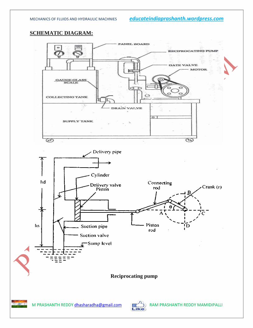
SCHEMATIC DIAGRAM:
Reciprocating pump

MECHANICS OF FLUIDS AND HYDRAULIC MACHNIES educateindiaprashanth.wordpress.com
M PRASHANTH REDDY [email protected] RAM PRASHANTH REDDY MAMIDIPALLI
TABULARCOLUMN:
S.NO Pressure
gauge
reading
Pd
(Kg/cm2)
Vacuu
m
gauge
reading
mm of
Hg(Ps)
Time
for 3
rev of
Energy
meter
(te)sec
Time for
10 cm rise
in
collecting
tank
(t)sec
Speed
NP
rpm
Discharge
(Q)
m3/sec
Input
Power
Pi
Output
Power
Po
η%
`
MECHANICS OF FLUIDS AND HYDRAULIC MACHNIES educateindiaprashanth.wordpress.com
M PRASHANTH REDDY [email protected] RAM PRASHANTH REDDY MAMIDIPALLI
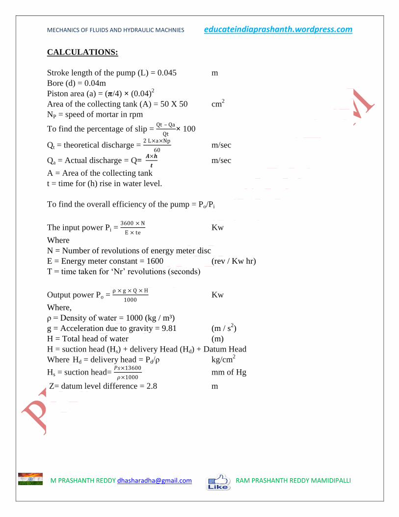
CALCULATIONS:
Stroke length of the pump (L) = 0.045 m
Bore (d) = 0.04m
Piston area (a) = (π/4) × (0.04)2
Area of the collecting tank (A) = 50 X 50 cm2
NP = speed of mortar in rpm
To find the percentage of slip = Qt – Qa
Qt× 100
Qt = theoretical discharge = 2 L×a×Np
60 m/sec
Qa = Actual discharge = Q= 𝑨×𝒉
𝒕 m/sec
A = Area of the collecting tank
t = time for (h) rise in water level.
To find the overall efficiency of the pump = Po/Pi
The input power Pi = 3600 × N
E × te Kw
Where
N = Number of revolutions of energy meter disc
E = Energy meter constant = 1600 (rev / Kw hr)
T = time taken for ‘Nr’ revolutions (seconds)
Output power Po = ρ × g × Q × H
1000 Kw
Where,
ρ = Density of water = 1000 (kg / m³)
g = Acceleration due to gravity = 9.81 (m / s2)
H = Total head of water (m)
H = suction head (Hs) + delivery Head (Hd) + Datum Head
Where Hd = delivery head = Pd/ρ kg/cm2
Hs = suction head= 𝑃𝑠×13600
𝜌×1000 mm of Hg
Z= datum level difference = 2.8 m

MECHANICS OF FLUIDS AND HYDRAULIC MACHNIES educateindiaprashanth.wordpress.com
M PRASHANTH REDDY [email protected] RAM PRASHANTH REDDY MAMIDIPALLI
GRAPH:
1. Actual discharge Vs Total head
2. Actual discharge Vs Efficiency
3. Actual discharge Vs Input power
4. Actual discharge Vs Output power
RESULT:
PRECAUTIONS:

MECHANICS OF FLUIDS AND HYDRAULIC MACHNIES educateindiaprashanth.wordpress.com
M PRASHANTH REDDY [email protected] RAM PRASHANTH REDDY MAMIDIPALLI
FRANCIS TURBINE
AIM:
To study the characteristic of a Francis turbine.
APPARATUS:
1. Francis turbine test setup
2. Tacho meter
3. stop watch
STARTING UP:
Modern Francis turbine in an inward mixed flow reaction turbine it is a medium
head turbine. Hence it required medium quantity of water. The water under pressure from
the penstock enters the squirrel casing. The casing completely surrounds the series of
fixed vanes. The guides’ vanes direct the water on to the runner. The water enters the
runner of the turbine in the dial direction at outlet and leaves in the axial direction at the
inlet of the runner. Thus it is a mixed flow turbine.
The unit essentially consists of a spiral casing and rotor assembly with runner
shaft and break drum, all mounted on suitable study base frame. An elbow fitted draft
tube is provided for the purpose of regaining the kinetic energy from the exit water and
also facilitating easy accessibility of the turbine due to its location at higher level than the
tail race. A transparent hollow Perspex cylinder is provided in between the draft bend and
the casing for the purpose of observation of flow at exit of runner. A rope brake
arrangement is provided to load the turbine. The output of the turbine can be controlled
by adjusting the guide vanes for which a hand wheel and a suitable link mechanism is
provided. The net supply head on the turbine is measured by a pressure and vacuum
gauge.
Make sure that before starting the pipeline are free from foreign matter. Also note
whether all the joints are watertight and leak proof. Prime the pump and start it with
closed gate valve. The guide vane in the turbine should also be in the closed position
while starting the pump. See that all the ball bearings and bush bearings in the units are
properly lubricated.
Then slowly open the gate valve situated above the turbine and open the cock fitted to the
pressure gauge and see that the pump develops the rated head. If the pump develops the
required head, slowly open the turbine guide vanes by rotating the hand wheel (which
operates the guide vanes through suitable link mechanism) until the turbine attains the
normal rated speed. Run the turbine at the normal speed (1250 rpm) for about one hour
and carefully note the following:
1. Operation of the bearings, temperature rise, noise etc.
2. Vibration of the unit.

MECHANICS OF FLUIDS AND HYDRAULIC MACHNIES educateindiaprashanth.wordpress.com
M PRASHANTH REDDY [email protected] RAM PRASHANTH REDDY MAMIDIPALLI
SPECIFICATION:
1. Spiral casing: made of cast iron with smooth inner surface.
2. Runner: made of gunmetal casting designed for efficient operation.
Accurately machined and smoothly finished.
3. Guide vane :consists of guide vanes rotating in gunmetal bushes
Mechanism operated by hand wheel through a link mechanism.
4. Shaft : stainless steel accurately machined
5. Bearing: one number ball bearing and one number taper roller bearing.
6. Draft tube bend: provided at the exit of the runner with a transparent
cylindrical window for observation of flow past the runner to the bend is
connected a draft tube of mild steel fabrication.
7. Brake arrangement: consists of a machined and polished cast iron brake drum,
cooling water pipes, internal water scoop discharge pipe, spring balances, screw
rod, and belt brake arrangement.
PROCEDURE:
1. keep the guide vane in full open position and slowly open the gate valve so that
the turbine runs at 1200 rpm
2. apply load supply by adjusting the screw rod connected to the belt, for loading
the brake drum and tighten the locknut
3. the speed gets reduced open the gate valve to an extent the speed is 1200 rpm
4. note the spring balance reading, pressure gauge reading & manometer reading
5. Repeat the above procedure for different loads & for different guide vane
opening.
SUPPLY PUMP:
1. Rated head : 20 m
2. Discharge : 2000lpm
3. normal speed : 1440 rpm
4. Power required : 15hp (11.2 Kw)
5. Size of pump : 100×100 mm
6. Type : centrifugal high speed single suction volute.
FRANCIS TURBINE:
1. rated supply head : 15.0 m
2. discharge : 2000lpm
3. rated speed : 1250 rpm
4. unit speed : 51.5 rpm
5. specific speed : 95.5 rpm
6. runner diameter : 150 mm

MECHANICS OF FLUIDS AND HYDRAULIC MACHNIES educateindiaprashanth.wordpress.com
M PRASHANTH REDDY [email protected] RAM PRASHANTH REDDY MAMIDIPALLI
7. no. of guide vanes : 8
8. brake drum diameter : 300 mm
FLOW MEASURING UNIT:
Size of venturi meter 100 mm
Throat diameter for venturi meter 60 mm
Manometer Double column deferential type.
TABULARCOLUMN:
S.no Gate
opening
Pressure
gauge
Vacuum
pressure
Manometer
reading
Speed of
rotation
Spring
balance
Pi Po η%
h1 h2 T1 T2

MECHANICS OF FLUIDS AND HYDRAULIC MACHNIES educateindiaprashanth.wordpress.com
M PRASHANTH REDDY [email protected] RAM PRASHANTH REDDY MAMIDIPALLI
SCHEMATIC DIAGRAM:
Francis turbine

MECHANICS OF FLUIDS AND HYDRAULIC MACHNIES educateindiaprashanth.wordpress.com
M PRASHANTH REDDY [email protected] RAM PRASHANTH REDDY MAMIDIPALLI
CALCULATIONS:
Input power (Pi) = (ρ×g×Q×h) watts
Flow rate of water Q = Cd ×𝑎1×𝑎2× 2𝑔𝐻
𝑎12−𝑎22 m
3/sec
d1 = dia. Of venture inlet = 100 mm
d2 = dia. Of venture throught = 60 mm
Cd = coefficient of discharge of venturimeter = 0.9
Where a1 = area of inlet of the venturimeter.
a2 = area of the venturimeter throat.
H = h1-h2 [𝑠1
𝑠2-1]
h = Total head of water (m)
h = suction head (hs) + delivery Head (hd) + Datum Head
Where hd = delivery head = Pd/ρ kg/cm2
hs = suction head= 𝑃𝑠×13600
𝜌×1000 mm of Hg
Output power (Po) = 2π×N×T
60 watts
T = (T1-T2) ×g × radi. Of break drum
radi. Of break drum = 0.15m
N = speed in tacho meter
Efficiency of the turbine ηm%= Po/Pi
Electrical efficiency = ηe% = po / Pi
po= electrical output = V × I watts
GRAPHS:
1. speed vs. output power
2. speed vs. efficiency
RESULT:
PRECAUTIONS:
MECHANICS OF FLUIDS AND HYDRAULIC MACHNIES educateindiaprashanth.wordpress.com
M PRASHANTH REDDY [email protected] RAM PRASHANTH REDDY MAMIDIPALLI
PELTON WHEEL TURBINE
AIM:
To conduct load test on Pelton wheel turbine and to study the characteristics of
pelton wheel turbine.
APPARATUS REQUIRED:
Venturi meter, Stopwatch, Tachometer, Dead weight.
DESCRIPTION:
Pelton wheel turbine is an impulse turbine, which is used to act on high loads and
for generating electricity. All the available heads are classified in to velocity energy by
means of spear and nozzle arrangement. Position of the jet strikes the knife-edge of the
buckets with least relative resistances and shocks. While passing along the buckets the
velocity of the water is reduced and hence an impulse force is supplied to the cups which
in turn are moved and hence shaft is rotated.
PROCEDURE:
1. The Pelton wheel turbine is started.
2. All the weight in the hanger is removed.
3. The pressure gauge reading is noted down and it is to be maintained constant for
different loads.
4. The Venturi meter readings are noted down.
5. The spring balance reading and speed of the turbine are also noted down.
6. A 5Kg load is put on the hanger, similarly all the corresponding readings are
noted down.
7. The experiment is repeated

MECHANICS OF FLUIDS AND HYDRAULIC MACHNIES educateindiaprashanth.wordpress.com
M PRASHANTH REDDY [email protected] RAM PRASHANTH REDDY MAMIDIPALLI
SCHEMATIC DIAGRAM:
Pelton Wheel Turbine

MECHANICS OF FLUIDS AND HYDRAULIC MACHNIES educateindiaprashanth.wordpress.com
M PRASHANTH REDDY [email protected] RAM PRASHANTH REDDY MAMIDIPALLI
TABULARCOLUMN:
S.no Gate
opening
Pressure
gauge
Vacuum
pressure
Manometer
reading
Speed of
rotation
Spring
balance
Pi Po η%
h1 h2 T1 T2
Electrical output
Load (kw)
Voltage
V
Current (I) A Speed(N)
rpm

MECHANICS OF FLUIDS AND HYDRAULIC MACHNIES educateindiaprashanth.wordpress.com
M PRASHANTH REDDY [email protected] RAM PRASHANTH REDDY MAMIDIPALLI
CALCULATIONS:
Input power (Pi) = (ρ×g×Q×h) W
Flow rate of water Q = Cd 𝑎1×𝑎2× 2𝑔𝐻
𝑎12−𝑎22 m
3/sec
d1 = dia. Of venture inlet = 65 mm
d2 = dia. Of venture throught = 39 mm
Cd = coefficient of discharge of venturimeter = 0.9
Where a1 = area of inlet of the venturimeter.
a2 = area of the venturimeter throat.
H= h1-h2 [𝑠1
𝑠2-1]
h = Total head of water (m)
h = suction head (hs) + delivery Head (hd) + Datum Head
Where hd = delivery head = Pd/ρ kg/cm2
hs = suction head= 𝑃𝑠×13600
𝜌×1000 mm of Hg
Output power (Po) = 2π×N×T
60 watts
T = (T1-T2) ×g × radi. Of break drum
radi. Of break drum = 0.15m
N = speed in tacho meter
Efficiency of the turbine ηm%= Po/Pi
Electrical efficiency = ηe% = po / Pi
po= electrical output = V × I watts
GRAPHS:
1. speed vs. efficiency
2. speed vs. power input
3. speed vs. power out put
RESULT:
PRECAUTIONS:

MECHANICS OF FLUIDS AND HYDRAULIC MACHNIES educateindiaprashanth.wordpress.com
M PRASHANTH REDDY [email protected] RAM PRASHANTH REDDY MAMIDIPALLI
KAPLAN TURBINE
AIM:
To study the characteristics of a Kaplan turbine
APPARATUS REQUIRED:
Venturimeter, Stopwatch, Tachometer, Dead weight.
DESCRIPTION:
Kaplan turbine is an axial flow reaction turbine used in dams and reservoirs of low
height to convert hydraulic energy into mechanical and electrical energy. They are best
suited for low heads say from 10m to 5 m. the specific speed ranges from 200 to 1000
The flow through the pipelines into the turbine is measured with the office meter fitted in
the pipeline. A mercury manometer is used to measure the pressure difference across the
orifice meter. The net pressure difference across the turbine output torque is measured
with a pressure gauge and vacuum gauge. The turbine output torque is determined with
the rope brake drum. A tachometer is used to measure the rpm.
PROCEDURE:
1. Keep the runner vane at require opening
2. Keep the guide vanes at required opening
3. Prime the pump if necessary
4. Close the main sluice valve and they start the pump.
5. Open the sluice valve for the required discharge when the pump motor switches
from star to delta mode.
6. Load the turbine by adding weights in the weight hanger. Open the brake drum
cooling water gate valve for cooling the brake drum.
7. Measure the turbine rpm with tachometer
8. Note the pressure gauge and vacuum gauge readings
9. Note the orifice meter pressure readings.
Repeat the experiments for other loads

MECHANICS OF FLUIDS AND HYDRAULIC MACHNIES educateindiaprashanth.wordpress.com
M PRASHANTH REDDY [email protected] RAM PRASHANTH REDDY MAMIDIPALLI
SCHEMATIC DIAGRAM:
Kaplan turbine

MECHANICS OF FLUIDS AND HYDRAULIC MACHNIES educateindiaprashanth.wordpress.com
M PRASHANTH REDDY [email protected] RAM PRASHANTH REDDY MAMIDIPALLI
TABULARCOLUMN:
S.no Gate
opening
Pressure
gauge
Vacuum
pressure
Manometer
reading
Speed of
rotation
Spring
balance
Pi Po η%
h1 h2 T1 T2
Electrical output
Load (kw)
Voltage
V
Current (I) A Speed(N)
rpm

MECHANICS OF FLUIDS AND HYDRAULIC MACHNIES educateindiaprashanth.wordpress.com
M PRASHANTH REDDY [email protected] RAM PRASHANTH REDDY MAMIDIPALLI
CALCULATIONS:
Input power (Pi) = (ρ×g×Q×h) kW
Flow rate of water Q = Cd 𝑎1×𝑎2× 2𝑔𝐻
𝑎12−𝑎22 m
3/sec
d1 = dia. Of venture inlet = 0.13 m
d2 = dia. Of venture throught = 0.078 m
Cd = coefficient of discharge of venturimeter = 0.9
Where a1 = area of inlet of the venturimeter.
a2 = area of the venturimeter throat.
H= h1-h2 [𝑠1
𝑠2-1]
h = Total head of water (m)
h = suction head (hs) + delivery Head (hd) + Datum Head
Where hd = delivery head = Pd/ρ kg/cm2
hs = suction head= 𝑃𝑠×13600
𝜌×1000 mm of Hg
Output power (Po) = 2π×N×T
60 watts
T = (T1-T2) ×g × radi. Of break drum
radi. Of break drum = 0.15 m
N = speed in tacho meter
Efficiency of the turbine η%= Po/Pi
Electrical efficiency = ηe% = po / Pi
po= electrical output = V × I watts
GRAPHS:
1. speed vs. efficiency
2. speed vs. power input
3. speed vs. power out put
RESULT:
PRECAUTIONS:
MECHANICS OF FLUIDS AND HYDRAULIC MACHNIES educateindiaprashanth.wordpress.com
M PRASHANTH REDDY [email protected] RAM PRASHANTH REDDY MAMIDIPALLI
MULTI STAGE CENTRIFUGAL PUMP
AIM:
To study the performance characteristics of a centrifugal pump
APPARATUS:
1. centrifugal pump test setup
2. stop watch
DESCRIPTION:
A centrifugal pump with a single impeller that can develop a differential pressure
of more than 150 psi between the suction and the discharge is difficult and costly to
design and construct. A more economical approach to developing high pressures with a
single centrifugal pump is to include multiple impellers on a common shaft within the
same pump casing. Internal channels in the pump casing route the discharge of one
impeller to the suction of another impeller. The water enters the pump from the top left
and passes through each of the four impellers in series, going from left to right. The water
goes from the volute surrounding the discharge of one impeller to the suction of the next
impeller.
A pump stage is defined as that portion of a centrifugal pump consisting of one impeller
and its associated components. Most centrifugal pumps are single-stage pumps,
containing only one impeller. A pump containing seven impellers within a single casing
would be referred to as a seven-stage pump or, or generally, as a multi-stage pump.
PROCEDURE:
1. Prime the pump, close the delivery valve and switch on the unit.
2. Open the delivery valve and maintain required head. Note the reading of pressure
gauge.
3. Note the corresponding reading from vacuum gauge.
4. Measure the area of the collecting tank
5. Close the drain valve and note the time for 10 cm rise of water level in the
collecting tank.
6. For different delivery head repeat the experiment.
7. For every set of reading note the time taken for 3 rev. Energy meter.

MECHANICS OF FLUIDS AND HYDRAULIC MACHNIES educateindiaprashanth.wordpress.com
M PRASHANTH REDDY [email protected] RAM PRASHANTH REDDY MAMIDIPALLI
SCHEMATIC DIAGRAM:
Centrifugal pump

MECHANICS OF FLUIDS AND HYDRAULIC MACHNIES educateindiaprashanth.wordpress.com
M PRASHANTH REDDY [email protected] RAM PRASHANTH REDDY MAMIDIPALLI
TABULARCOLUMN:
S.
N
O
Pressure
readings
Pressure
gauge
reading
Pd
(Kg/cm2)
Vacuum
gauge
reading
mm of
Hg(Ps)
Time for 3
rev of
Energy
meter
seconds
(te)
Discharge
(Q)
m3/sec
Input
Power
Pi
Output
Power
Po
η% h1 h2

MECHANICS OF FLUIDS AND HYDRAULIC MACHNIES educateindiaprashanth.wordpress.com
M PRASHANTH REDDY [email protected] RAM PRASHANTH REDDY MAMIDIPALLI
CALCULATIONS:
Flow rate of water Q = Cd 𝑎1×𝑎2× 2𝑔𝐻
𝑎12−𝑎22 m
3/sec
d1 = dia. Of venture inlet = 65 mm
d2 = dia. Of venture throught = 39 mm
Cd = coefficient of discharge of venturimeter = 0.9
Where a1 = area of inlet of the venturimeter.
a2 = area of the venturimeter throat.
H= h1-h2 [𝑠1
𝑠2-1]
h = Total head of water (m)
h = suction head (hs) + delivery Head (hd) + Datum Head
Where hd = delivery head = Pd/ρ kg/cm2
hs = suction head= 𝑃𝑠×13600
𝜌×1000 mm of Hg
1. The work done by the pump is given by Po = ρ × g × Q × H
1000 Kw
Where,
ρ = Density of water (kg / m³)
g = Acceleration due to gravity (m / s2)
H = Total head of water (m)
2. The input power Pi = 3600 × N
E × te Kw
Where
N = Number of revolutions of energy meter disc
E = Energy meter constant = 150 (rev / Kw hr)
T = time taken for ‘Nr’ revolutions (seconds)
3. The efficiency of the pump = (Po/ Pi) ×100 %
MECHANICS OF FLUIDS AND HYDRAULIC MACHNIES educateindiaprashanth.wordpress.com
M PRASHANTH REDDY [email protected] RAM PRASHANTH REDDY MAMIDIPALLI
GRAPH:
1. Actual discharge Vs Total head
2. Actual discharge Vs Efficiency
3. Actual discharge Vs Input power
4. Actual discharge Vs Output power
RESULT:
PRECAUTIONS:

MECHANICS OF FLUIDS AND HYDRAULIC MACHNIES educateindiaprashanth.wordpress.com
M PRASHANTH REDDY [email protected] RAM PRASHANTH REDDY MAMIDIPALLI