Chapter 9: Electronic Commerce Software Electronic Commerce, Sixth Edition.

DEPARTMENT OF COMMERCE AND INDUSTRIAL DEVELOPMENT
Mexican Official NORM NOM-001-SCFI-1993, electronic apparatuses - household electronic apparatuses supplied by different sources of electrical power safety requirements and testing methods for type approval.
At the margin a seal with a National Stamp that says: Estados Unidos Mexicanos.- Department of Commerce and Industrial Development.
MEXICAN OFFICIAL NORM NOM-001-SCFI-1993, “ELECTRONIC APPARATUSES - HOUSEHOLD ELECTRONIC APPARATUSES SUPPLIED BY DIFFERENT SOURCES OF ELECTRICAL POWER - SAFETY REQUIREMENTS FOR TYPE APPROVAL.”
Department of Commerce and Industrial Development by means of the General Direction of Norms, with basis in articles 34 from the Organic Law of the Federal Public Administration,1o, 39 fraction V, 40 fraction I and II, 47 fraction IV of the Federal Law regarding Metrology and Normalization, 9 th and 17, fraction I of the Internal Ruling of the Department of Commerce and Industrial Development, and 4th, fraction X, section a) from the agreement that ascribes Administrative Units and Delegates Authorities in Subsecretaries, Major Official, General Directors and other Subalterns of the Department of Commerce and Industrial Development, published in the DOF on September 12 1985, and
CONSIDERING
That the National Plan of Development is indicated that it is necessary to adequate the regulator margin of the national economic activity.
That being responsibility of the Federal Government, to procure the measures which are necessary to guarantee that the products and services which are commercialized in national territory are safe and do not represent a danger to the user or consumer regarding their bodily integrity.
That the Federal Law about Metrology and Normalization establishes that the Mexican Official Norms are constituted as an ideal instrument for the protection of these objectives, I have expedited the following:
Mexican Official Norm NOM-001-SCFI-1993, “ELECTRONIC APPARATUSES - HOUSEHOLD ELECTRONIC APPARATUSES SUPPLIED BY DIFFERENT SOURCES OF ELECTICAL POWER - SAFETY REQUIREMENTS AND TESTING METHODS FOR TYPE APPROVAL.”
For these effects, the validity of the Mexican Official Norm mentioned above will be understood in the following manner:

a) The following day to the publication in the DOF in relation to the specifications and electric rigidness testing, current leak and insulation resistance, as well as labeling, and
b) In a complete manner starting from January 1, 1994.On the other hand, in certification matter:The certifications granted for the products to which the field of application refers in the Mexican Official Norm, before the validity of the present Norm are still valid on the terms at which it is granted, without prejudice that the products which are commercialized in the country must comply with the Mexican Official Norm valid in the terms in which it is specified for its validity.The people that have a valid certificate, should obtain within the following 120 natural days to the validity of this Norm, the registration number which corresponds to the General Direction of Norms, same that should have the password enclosed with the official “NOM.”
Suffrage Effective. No Reelection.Mexico D.F., October 8, 1993.- The General Director of Norms, Luis Guillermo Ibarra- Rubric.
NOM-001-SCFI-1993 ELECTRONIC APPARATUSES - HOUSEHOLD ELECTRONIC APPARATUSES SUPPLIED BY DIFFERENT SOURCES OF ELECTRICAL POWER -SAFETY REQUIREMENTS AND TESTING METHODS FOR TYPE APPROVAL.
1. PURPOSE
This Norm establishes the safety requirements which must comply by design and construction the electric apparatuses which utilize as their supply electric power from the public service as well as other sources of power such as pilas, batteries, accumulators, etc. with the purpose of avoiding and eliminating the following risks of bodily incomulity of the users and for the conservation of their goods.
1.1 Electric discharges caused by power leaks or discharges among the apparatuses and the human body.
1.2 Burns of the human body caused by accidental or voluntary contact with accessible overheated parts.
1.3 Bodily harm and material affectations caused by the mechanical instability of the apparatuses and/or by the functioning of its movible parts.
1.4 Bodily harm and material affectations by fire or conflagration originated by the apparatuses during functioning.
1.5 Pathologic and genetic consequences from the exposure of the human body to excessive dosages of ionizing radiation emitted during functioning of the apparatuses which have included circuits with same or greater potentials to 15 kV (crest.)

Each safety requirement of the apparatuses is defined in terms of limits and corresponding testing methods, in such a manner that the present Norm constitutes a unified basis and of common understanding which permits the designers, manufactures, buyers, sellers, users and competent authorities to incorporate, demand and evaluate the safety upon unified criteria with true and repetitive results.
2. FIELD OF APPLICATION
2.1 The requirements and testing methods of this Norm are applied to the following household electronic apparatuses which utilize for their supply electric power from the public networks as well as other sources of power such as pilas, batteries or accumulators and will be designed to operate to 3 000 m of altitude above the sea level:
Raioreceptors of one more frequency commercial bands and one or more modulation modalities of the porter.
Television receptors in black and white as well as in color, TV Video projectors. Sound amplifiers. Sound recorders and/or reproducers and image with magnetic tape. Manual and automatic turntables. Acoustics boxes with integrated amplifiers. Disk reproducers and magnetic tape digitally recorded. Remote controls for any of the apparatuses included in this Norm. Antenna signal amplifiers. Microwave ovens. Monitors. Separate sources for the supply of apparatuses and substitution of pilas and
batteries. Any combination of two or more apparatuses mentioned above, such as
radiogramophones, consoles and modular equipment. Other apparatuses, implements, accessories and electronic devises destined
specifically for household. Electronic musical instruments. Electronic accessories such as rhythm generators, tone generators (as
individual equipment), musical synthezicers, and everything that is used with electronic and non-electronic instruments.
Video games and apparatuses generators of video games which are connected to a TV
2.2 This Norm deals exclusively with the safety of household electronic apparatuses and does not cover other characteristics or performance specifications of these apparatuses, which are established in the corresponding norms for each product.
2.3 This Norm is applied up to where it would be possible to professional, scientific or industrial equipment if in the meantime there does not exist a Norm which specifies the safety for these.
2.4 These are excluded from the ambit of this Norm.2.4.1The electronic apparatuses which supply require nominal voltage above
433 V (rcm) between phases for triphase supply 250 V (rcm) in any other case
For which the corresponding Norm must be utilized to apparatuses and scientific and industrial components.
2.4.2 The electronic apparatuses designed specifically to operate at altitudes above 3 000 m above sea level, for which the corresponding Norm must be utilized for apparatuses and components for aeronautic or special investigation.
2.4.3 This Norm is applicable to National Fabrication products as well as imported.
3. REFERENCES
For the correct application of this Norm it is necessary to consult the following valid Mexican Norms.NMX-1-7/12 Equipment and electronic components. Environmental and durability testing methods. Part 2. Tests. Ca test: Stationary humid heat.NMX-1-19 Graphic symbols used in electronics and electric communications.NOM-008-SCFI General Sister of Units of Sister-Measure (SI) of Units.
4. DEFINITIONS For the correct application of this Norm the following definitions must be considered:
4.1 Type test of a product.In the complete series of tests which are taken on a number of specimens representative of a determined type of product, with the purpose of determining if this product complies with the requirements of this Norm and therefore it may be considered as safe for the user.4.2 Manual operation It is that which is executed directly with the hand without the need to use any tool, including coins or other object.4.3 Accessible part.It is any part of the apparatus that may be touched with a finger of test (see figures 1 and 2.)4.4 Live partIn any conductor part of the apparatus, which establishes contact with the human body, may provoke chocks or electric discharges.4.5 Critical distance on insulation.

It is the shortest distance measured at air among the conductor parts, following the profile of insulation (see figure 3.)4.6 Critical distance at air.It is the shortest distance measured at the air among the conductor parts (see figure 3.)4.7 Electric networkIt is any supply line of electric power with a voltage of operation above 34 V (crest,) which is also used to supply the specific apparatuses in chapter 2.4.8 Nominal voltage of supply.It is the value of the voltage or interval of voltages of the electric network.4.9 Part directly connected to the network.It is that part of the apparatus which is electrically connected to the electric network of supply so that the connection between that part and any other pole, phase or neuter of the network, originates a current equal or above 9 A, medium value of the quadratic root (rm.) or efficacious value.
Note.- A current of 9 A has been selected as the minimum current of rupture of a fuse at 6 A in the tests that are taken to determine which parts are connected directly to the network, the fuses of the apparatuses must not short-circuit.
4.10 Parts connected conductivity to the network.It is any apart or element of the apparatus which is connected electrically to
the network of supply so that a connection through the resistor of 2 kW between that part or element and any other network pole, originates at the resistor a current above 0.3 ma (crest,) without the apparatus being connected to tierra.
4.11 Supply UnitIt is the accessory or devise that utilizes the power of the electric network and provides the supply to one or more apparatuses.4.12 Battery eliminatorUnit of supply which may be utilized instead of batteries to supply an electronic apparatus.4.13 Portable apparatus.Apparatus designed to be easily transported by hand and which weight is equal or below 15 kg.4.14 Terminal.Devise part of an apparatus through which a connection is executed to external conductors or other apparatuses. It may contain various terminal contacts, such as outlets, clavijas, receptacles, and similar.4.15 Safety terminal of tierra.
Accessible terminal to which the different parts of an apparatus remain directly connected which must landed for safety reasons.
4.16 Functional terminal of tierra.Terminal to which circuits or parts of the apparatus may be connected that result convenient to connect to tierra for reasons other that safety.4.17 Devise limited of temperature.

Devise which prevents the maintaining of excessively high temperatures in certain parts of the apparatus, disconnecting these parts from their supply.4.18 Safety SwitchDevise which interrupts the connection of the apparatus to the network supply, when an apparatus is opened retrieving the cover lids of parts of the cabinet.4.19 Apparatuses of variable consumption.Apparatus in which the consumption supply voltage may vary in more than 15% due to the changes in impedance of the outlet circuits or in the parameters of the signal --------.As examples of this type of apparatuses are considered sound amplifiers, supply sources, transreceptors, etc.4.20 Voltage of minimum entrance for the nominal output voltage,
limited in temperature.Voltage which must be applied to a couple of entrance terminals of a variable consumption apparatus, with a curve of plain response, if it is adjustable, to obtain the output nominal voltage limited in temperature, being the apparatus adjusted to maximum sensitivity and a frequency of 1 000 Hz, unless another frequency is specified by the manufacturer.4.21 Nominal output voltage.Voltage measured in a couple of output terminals of a variable consumption apparatus and that corresponds to the nominal output voltage.4.22 Printed circuit.Plate of base material that includes all the perforations destined to the setting of the components and that contains at least one conductor track.4.23 Conductor track.Configuration of materials electronically conductors that make up an electric circuit.4.24 Basic insulation.Insulation that is applied to the live parts to provide a basic potation against electric discharge.4.25 Supplementary insulation.Insulation independent from basic insulation which is applied in addition to the basic insulation with a purpose of providing a protection against electric shock, in case of a failure of the basic insulation.4.26 Double insulation.It is the combination of basic insulation and supplementary insulation.4.27 Reinforced insulation.Insulation system which is applied to the live parts. Capable of providing a degree of protection against electric shock equivalent to double insulation, under the conditions which are specified in this Norm.Note.- The term “insulation system” does not imply that the insulation must be one single homogenous piece. It may be formed by various

layers, which may not be tested individually as a basic or supplementary insulation.4.28 Class I apparatus.Apparatus in which the protection against electric shock is not limited exclusively to a basic insulation, but it excludes an additional safety measure which consists of a connection to tierra of all the accessible conductor parts of the apparatus itself through which the conductor that forms part of the supply cord and which is connected to the home electric installation, which includes a third conductor and tierra contact devise in this manner, the accessible conductor parts can never turn dangerous in case of an existing basic insulation failure because they are permanently landed and an eventual short-circuit between the phase of the network and the accessible parts provoke the interruption of a fuse and the consequent separation between the electric network and the apparatus.Note.- These apparatuses may also include parts and components which meet the class II requirements.4.29 Class II apparatus.Apparatus in which the protection against electric discharges is not based exclusively in a basic insulation, but it includes an additional safety measure just as a double insulation or a reinforced insulation, without the existence of a connection system of safety tierra, or its supply cord, or the home electric installation.4.30 Network interrupter for total disconnection.Interrupter or interruption system destined to disconnect all the parts of the apparatus from all the supply network poles.Note.- An example of an interruption system is a combination of a reliever and an interrupter for controlling the reliever.4.31 Network one-pole switchInterrupter or interruption system destined to disconnect all the energized parts of an apparatus of a single pole from the electric network of supply.
Note.- An example of an interruption system is a combination of a reliever and an interrupter to control the reliever.
4.32 General interrupter.It is an interrupter or a system destined to disconnect circuits not related to the supply, such as the sound or image, etc.
Note.- An example of an interruption system is a combination of a reliever and an interrupter for the reliever.
4.33 Electronically musical instrumentIndicates an electronic apparatus such as an organ, piano or musical synthezicer, which produces music under the control of the operator.4.34 Remote control device.Devise to control an apparatus from a certain distance, being by mechanic and electric action or by means of radiation in any frequency band including the ultraccoustics and the infraoptic.4.35 Input transducer.
Apparatus or devise which is utilized to convert the energy of a non-electric signal, examples: Phonocaptors, microphones, magnetic reproducer heads and similar.4.36 Output transducer.Apparatus or devise utilized to convert the energy of an electric signal into any other form of energy of information, examples: altavoces, headphones, cinescopios and similar.4.37 Audio amplifierAudio amplifier apparatus, independent is the audio amplifier action of an apparatus, for which the Norm is applied.4.38 Nominal impedance of the output circuit.Nominal impedance of an apparatus of variable consumption specified by the manufacturer, with which it charges the output circuit.4.39 Minimum voltage input for the nominal output power.The voltage which must be applied to a couple of input terminals of an apparatus of variable consumption with a curve of plain response, if it is adjustable to obtain the nominal output power, the apparatus being adjusted at maximum sensitivity and at a frequency of 1 000 Hz, unless another frequency is specified by the manufacturer.4.40 Nominal output power limited in temperature.It is the power of an apparatus of variable consumption, specified by the manufacturer, which this apparatus is capable of providing continuously at the impedance of nominal charge without exceeding the maximum temperature permitted at any point, remaining the frequency within the interval specified by the manufacturer.Note.- It is possible that for certain frequency values, the apparatus may sustain a higher output power continuously than the nominal output power limited in temperature.4.41 Nominal output power.It is an apparatus of variable consumption, it is the dissipated power in the nominal charge impedance. This power and the corresponding distortion are specified by he manufacturer at the frequency of 1 000 Hz, unless another frequency is specified.Note.- Generally an apparatus of variable consumption does not provide the nominal output power continuously. This power appears only during short periods; for example in modulation crests.4.42 Nominal input voltage of a speakerIt is the maximum voltage specified by the manufacturer which may be provided by an altavoz, at the frequency of 1 000 Hz, unless another frequency is specified.4.43 Nominal input impedance of an altavoz.Impedance specified by the manufacturer, for an altavoz at a frequency of 1 000 Hz, unless another frequency is specified.4.44 Nominal input power of an altavoz.

Maximum power specified by the manufacturer which may be applied to an altavoz at the frequency of 1 000 Hz, unless another frequency is specified.
Note.- Generally the nominal input power cannot be provided continuously to an altavoz. This power appears only during short periods, for example, in modulation crest.
4.45 Output power without cut.In an audio amplifier the maximum power is indicated with an available senoidal wave, dissipated at a measured nominal charge impedance of 1 000 Hz, just before the cut is initiated. In the case where the amplifier is not designed to operate at 1 000 Hz, a test frequency must be utilized to the nominal crest response of the amplifier.
5. SPECIFICATIONS
The apparatus included in the field of application of this Norm must be designed and manufactured in such manner that they do not cause any harm whatsoever to the customers during functioning, under normal conditions of operation as well as under abnormal conditions, particularly when it refers to:
5.1 Personal protection against electric shock.5.2 Personal protection against the effects of excessive temperature.5.3 Personal protection against the effects of mechanical instability of the
apparatuses and their parts in movement.
6. TESTING METHODS
6.1 The compliance with the indicated in chapter 5 is verified taking the specified tests in 6.2 that conform with the general rules which are provided as follows:
6.1.1. The tests included in this Norm are tests for the evaluation and approval of a product type.
6.1.2 All the tests are taken in the same order specified by this Norm regarding one same apparatus, as much as it would be possible, unless it is specified otherwise in particular Norm.
6.1.3 Unless another condition is specified in the particular Norm, the tests are taken under the following normalized environmental conditions.
Environmental temperature from 15 to 35°CRelative environmental humidity from 45 to 75%Atmospheric environmental pressure from 733 to 1 060 mbar (550-800 mm
Hg)
6.1.4 For the arbitrary tests, one of the three alternatives from chart 1 must be utilized.
Chart 1.- Environmental conditions for arbitrary tests.

Environmental conditions Alternatives
TemperatureRelative humidityAtmospheric pressure
a b c20 ° 2°C 23 ° 2°C 27 ° 2°C60 ° 70% 45 aι 55% 60 aι 70%from 733 to 1 000 mbar (550 to 800 mm Hg)
6.1.5. Unless otherwise specified.The voltages and powers are practically senoidal form.
The power and voltage measures must be done with apparatuses which do not affect sensibly the values to be measured.
Normal conditions of operation.Consists in the most unfavorable combination of the conditions found at
normal practice to know.6.2.1 Any position of normal use of the apparatus under testing without
the normal ventilation being impeded. This position is obtained placing the apparatus on a horizontal support which dimensions are not smaller than the base of the apparatus, leaving a free space of no less than 5 cm in depth behind itself.
Note.- The tests on the apparatus which form part of a unit not provided by the same manufacturer of the apparatus must be taken following the instructions of use provided by the manufacturer of the apparatus in question, specifically those related with the adequate ventilation of the apparatus.6.2.2 Applying a voltage of supply of 90% and 110% of any supply
voltage specified as nominal to which the apparatus may be connected. For the apparatus which have a specified interval of supply of voltage not requiring the voltage adjuster devise a supply voltage of 90% of inferior limit and a 110% of superior limit of any interval of supply specified voltage. The frequency of the specified voltage must be 60 Hz. The apparatuses which are supplied indistinctively at c c or a d a are tested at both modalities of supply.
6.2.3 Any position of the controls which are accessible to the customer for its manual adjustment.
6.2.4 Any terminal de tierra being connected or not to a tierra and any pole of the source of insulation supply, utilized during the test, being landed.
6.2.5 With or without other apparatuses connected which form part of the unit or system.
6.2.6 In the apparatuses which include one or more motors, the conditions must be reproduced of the loads of each motor, according to the instructions for each use, provided by the manufacturer of the reasonable conditions to assume if they are the least favorable during its performance.

Note.- When the apparatus which include one or more motors are tested, the other parts of the apparatus must not be disconnected during the test.6.2.7 The battery eliminators or other sources of supply are tested being
connected to its output a load which its impedance is equal to the specified load by the manufacturer, and if they are also tested without load.
6.2.8 The battery eliminators which dimensions correspond to the one of a pila or battery or to a unit of pilas, are tested in the interior of a compartment for batteries which offer the most unfavorable conditions of thermal radiation, in addition to that the eliminators of batteries destined tot be installed in the interior of the apparatus, are tested by being installed in the corresponding apparatus according to the instructions of the manufacturer.
6.2.9 The apparatus designed to be utilized with legs which may be taken apart or bases provided by the own manufacturer, must be tested with and without bases or dismountable legs.
7. LABELING
7.1 Generalities.In relation to the safety of the apparatus they must be labeled according to 7.2, 7.3, 7.4 and 7.5. The labeling must be:
Discernible, legible and indelible, in such a manner that it does no provoke confusions or wrong interpretations.
The compliance to the specified above must be proved by visual exam and by the following test.The labeling must not be erased when rubbed slightly with a piece of cloth or cotton impregnated with white gasoline or water.The information must be placed preferably on the exterior of the apparatus excluding the base. Although, it is admissible that the manufacturer locates it in another place, for example, an easily movable plate of a turntable, on the exterior of the base of a small or light apparatus, being indicated the location on the labeling in the operation manuals of the apparatus.
The symbols for the measure and quantity units must be according to the established by the NOM-800-SCFI. The graphic symbols utilized, must be according with the NMX-1-19.The compliance with the indicated above, must be proven by visual exam.
7.2 Identification.The apparatus must be identified by:7.2.1 Name of manufacturer, registered brand or both.7.2.2 Model number, commercial name or both.7.2.3 Brand or approval password of sale and corresponding purpose to
products which utilized, generate or transform the electric energy to suit the valid legislation.
The compliance to the indicated before is proved by visual exam.

Note.- It is permissible that the class II apparatus be labeled with the symbol of a double square.
This symbol must be placed in such a manner that it is obvious that forms part of the technical information and does not result possible to confuse it with the name of the manufacturer.
7.3 Supply labeling.The apparatuses must be labeled with the following information:7.3.1 Nature of supply.Alternating current ca or the symbol ≅
Continuous current cc or the symbolNote.- Label the apparatus in which ca may be utilized as well as cc, with ca-
cc or with the symbols.7.3.2 Nominal voltage of supply or supply voltage margin which may be
utilized for the performance of the apparatus, without the need of adjusting a conmutator or voltage changer.
7.3.3 The apparatuses that can adapt to different supply voltages by means of conmutator movable devises may be operated by the customer, must be labeled in such a manner that each indication of voltage for which the apparatus is adjusted results visible from the exterior when the apparatus is ready for its use.
7.3.4 If the apparatus is designed in such a manner that the customer may alter the supply voltage, the action of changing the adjustment must also change the indication of the voltage.
7.3.5 If the apparatus is provided of more than one voltage conmutator, it must be clearly indicated the fact that various devises must be adjusted to the same voltage.
7.3.6 Nominal supply frequency or frequency margin in Hertz, if the safety of the apparatus depends on the value of the supply frequency.
7.3.7 When there is a outlet or terminal devise utilized to provide to other equipment(s), it must be labeled on the other side of the outlet or voltage devise (if this one defines the voltage of the network) and the power or current which may be obtained.
The compliance of the specified above must be proved by visual exam.7.4 Terminal labeling.The terminals must be labeled with the following symbols: 7.4.1 The tierra terminal when it exists:7.4.2 Devises and/or terminals which are accessible parts and in which
the voltage exceeds 34 V (crest) under normal conditions of operation, except the terminals for the main source and the outlets according to the indicated in 7.3: γ
The arrow must be pointing the corresponding terminal devise.Note.- This symbol must be utilized only to indicate the existence of a live terminal and must not be utilized to indicate non-live terminals with the purpose of avoiding the requirements of more severe insulation.
The compliance of the above indicated must be proved by visual exam. The brand of the safety tierra does not need to be visible from the exterior (see 14.2.)7.5 Warning for apparatus of mixed supply.In the apparatus which may be supplied by alternating current from the network as well as batteries, the operation manual must indicate that the mentioned apparatus must not be exposed to leaking of splashing of liquids.7.6 Optional additional data.With informative purposes it could be useful to add:7.6.1 The nominal value of consumption in Watts of the nominal current
of operation.7.6.2 The voltage of indications of each output terminal devise for
independent altavoces with two of the data which is given as follows:7.6.2.1 The voltage of nominal output or the margin of output nominal
voltages in Volts.7.6.2.2 The impedance of nominal output or the margin of output
impedance in Ohms. Ω7.6.2.3 The nominal consumption of the apparatus in Watts.7.6.3 The specification for the testing of the apparatuses of variable
consumption may include the following:7.6.3.1 Power of nominal output in Watts.7.6.3.2 Power of nominal output limited in temperature in Watts by degree
Celsius.7.6.3.3 Impedance of nominal loads of voltages of nominal output of all the
output circuits.7.6.3.1 Voltage of minimum input corresponding to the power of nominal
output.7.6.3.4 Voltage of minimum input for the power of nominal output limited in
temperature.7.6.3.5 Margin of the signal frequencies for which the apparatus has been
designed.7.7 Devises of replaceable thermal liberation. For the devises of replaceable thermal liberation adequate information must be provided to insure its correct replacement.When in a service documentation of an apparatus, for example in an electric diagram or in a list of parts, is required to indicate which are the components involved with the assurance that must be only substituted with the specified components by the documentation, then the following distinctive symbol must be utilized: ∆ It is not necessary to place this symbol on the components themselves or on the printed circuits of the apparatuses.The compliance of the above is verified by visual inspection.
8. WARMING UNDER NORMAL CONDITIONS OF OPERATION

8.1 Being operated under normal conditions none of the parts of the apparatus must reach temperatures which affect the safety conditions.
8.1.1 The compliance of the above be proven through the measuring of the temperature under normal conditions or operation, when the condition of thermal stability has been obtained in the apparatus.
Note.- In general it is considered that the apparatus reaches its thermal stability after 4 h of continuous operation. 8.1.3 The temperatures are determined:
In the case of spools, by the resistance variation method, In all the other cases by any method convenient.
Note.- During the measuring of the resistance of the spools, one must be careful that the influence of circuits or loads connected to these be depreciable.8.1.4 The increments in temperature must not exceed the values given in
column 1 from chart 2.8.1.5 During the testing the fuses must not open.The values of the increments of temperature refer to a maximum environment temperature of 45°C for tropical climates, but the measures may be done under the normalized environment conditions indicated in 6.1.3.
Chart 2.- Example of the maximum increments of temperature.Parts of the apparatus maximum increments of temperature
°CExternal parts Metallic partsknobs, handles, etc. Cabinets(see note 1) Non metallic partsknobs, handles, etc. (see note 2)Cabinets (see 50 notes 1 and 2)
Normal conditions of operation20
30
4050
Notes:
1.-For the areas in which none of the dimensions exceed 5 cm and which is not probable that they be touched during normal use of the apparatus, the increments of temperature are permissible up to 55°C under normalized environment conditions.2.-If during the measuring higher increments of temperature are found than those which are permitted by the type of insulation material, the nature of the material is the determinant factor to establish if the apparatus complies. All the materials must comply with the requirements of their particular Norms.
9. WARMING TO ELEVATED ENVIRONMENT TEMPERATURES
9.1. Resistance to heat without external forces.
The apparatus must be sufficiently resistant to heat. The compliance to the indicated must be proven under the normalized environment conditions indicated in 6.1.3, with the exception that the environment temperature must be between 45°C and 50°C which requires a room or cabinet for testing to dry heat.
The duration of the test must be of 4 h.The testing room or cabinet with the apparatus inside it, is taken to the
mentioned temperature and is maintained to that temperature during the test.To the temperature obtained during the test, the materials which are utilized to
seal and impregnate must not have fluidified or softened to such a degree that it jeopardizes the protection against the danger of electric discharge.
9.2 Resistance to heat under external forces.The cabinet of the apparatus must be sufficiently resistant to elevated temperatures under external forces.The compliance of the indicated must be proven through the tests which are enunciated as follows, to the maximum temperature that each part of the cabinet obtains during the test mentioned in 10.1.By means of the rigid testing finger (see figure 1) a force of 50 N is applied (51kgf,) directed to the inside and applied during 10 s in all the points where this is possible, including the covers of textile material of the altavoces. By means of the testing hook (see figure 4,) directed to the outside with a force of 20 N (2.04 kgf) during 10 s in all the points where this is possible.
Note.- The apparatus does not need to be connected to its supply during these tests.The live parts must not be accessible and the covers of cloth must not touch the live parts.After these tests the apparatus must not show damage in the sense given in this Norm.The force must be applied by a tip of the testing finger to avoid lever of wedge actions.Note.- For example a rigid testing finger directed in perpendicular form as shown previously, may be applied around any opening or in any place where the deformation may cause an opening.At the same time an articulate testing finger (see figure 1) is applied without force of determine which live parts have come to be accessible parts.
10DANGER OF ELECTRIC SHOCK UNDER NORMAL CONDITIONS OF OPERATION.
10.1 Testing in the exterior of the apparatus.10.1.1 Generalities.10.1.2 Arrows, Axis, and Shoots of operation.Arrows, axis and shoots of operation which are live parts must remain adequately protected against risks of accidental contact.The compliance of the indicated above is verified by means of a testing chain of 2 mm of diameter (see figure 5.)

It must not be possible to establish electric contact with shoots of operation or with the screws or setting prisoners of the knobs from the exterior, when the chain is suspended freely and it is made to slide upon each one of the elements.10.1.3 Perforations for ventilation.The ventilation orifices and other perforations which are found in coincidence with live parts, must be designed and placed in such a manner that a freely suspended strange body (for example a collar,) being introduced in to the apparatus may not come in contact with a live part.The compliance with the above is verified by means of a metallic testing bolt of 4 mm of diameter and 100 mm of length (see figure 6.) This bolt is suspended freely by one of its extremities by means of a wire and it is left to penetrate in all the orifices and perforations of the apparatus up to its maximum length, being the apparatus placed in is normal position of operation.The testing bolt must not come in contact with any live part.10.1.4 Pre-adjustment controls.If one of the perforations made in a cabinet or in the cover to permit the access to pre-adjustment controls, it must be labeled specifically for this purpose and the adjustment of this control requires of an untier or other tool, then the adjustment to it must not involve danger of electric discharge.The compliance of the above is verified through the perforation of the testing metallic bolt of 2 + 0.1 mm of diameter and 100 mm of length and applying it in each position possible pressing it in case of doubt with a force of 10 N (10.02 kgf.) The bolt must not get to be live part.10.2 Construction requirements.10.2.1 The insulation of the live parts must not be constituted by
hygroscope materials such as non-impregnated wood, paper and analog fibrous materials.
The compliance with the above is verified by means of visual inspection and in case of doubt, by the following test:One specimen of the material in question with dimensions of at least 75 mm of length and 50 mm of width is subjected to the test Ca of the NMX-1-7/12 during 7 days (168 h) with a temperature of 40 ± 2°C and a relative humidity between the 90 and 95%.
After the test, the specimen must endure the specified conditions in 11.2.Note.- If it is necessary the test is done on more than one specimen.
10.2.2 The apparatuses must be designed and manufactured in such a manner that they do not offer danger of electric discharges from parts directly accessible when manually removing a cover, the top, a hatchway, etc.
The compliance of the above is verified according to the indicated in 10.2.3 or 10.2.4.

10.2.3 In the class I apparatuses the accessible metallic parts must be separated from the live parts by means of basic insulation which comply with the requirements from section 10.2.4 a) (Except for those parts of the apparatus which are class II, see 4.29.)
Note.- This requirement is not applied to those insulation which short-circuits does not cause a risk of electric discharge, such as the case in which one terminal of a secondary of a transformer of separation which is connected to an accessible metallic part, its other terminal must not satisfy any particular demand of the insulation with relation to the same accessible metallic part.
The class I apparatuses must be provided with one safety tierra terminal or a contact in which they may be reliably connected to the accessible metallic parts, except those isolated parts of the live parts by means of an insulation which complies with the requirements of 10.2.4 or those which are found to be protected by means of a metallic part reliably connected to a safety tierra terminal.
Note.- Examples of such metallic parts are a metallic screen in a transformer between the primary and secondary spools, a metallic chassis, etc.
10.2.4 For class II apparatuses, the accessible parts must be isolated from the live parts by means of double insulation specified in section a) or by means of reinforced insulation indicated in section b) in this section.
This requirement is not applied to the insulation which short-circuit does not cause any risk of electric shock, such as the case in which a terminal of secondary of a transformer of separation which is connected to an accessible metallic part, its other terminal must not satisfy any particular demand of insulation with relation to the same accessible metallic part.A component may be set in parallel with basic and supplementary insulation, double or reinforced. The basic and supplementary insulation may have a capacitor in parallel which complies with the requirements of this Norm.The double and reinforced insulation, may have only one capacitor in parallel which complies with the requirements of this Norm, if an appropriate and reliable procedure is complied to verify the uniformity and conformity continues with the daily production of this particular Norm.As an alternative two capacitors are required in series with the same nominal values complying with each one of the requirements of this Norm.On the other hand, the external insulation of a capacitor of the isolated type must not be reinforced by means of a capacitor in parallel or by means of the double insulation utilized in the construction of the apparatuses.a) If the accessible parts are separated from the live parts by means of
basic and supplementary insulation, the following must be applied: Each one of these insulation must comply with the requirements of chapter 11.
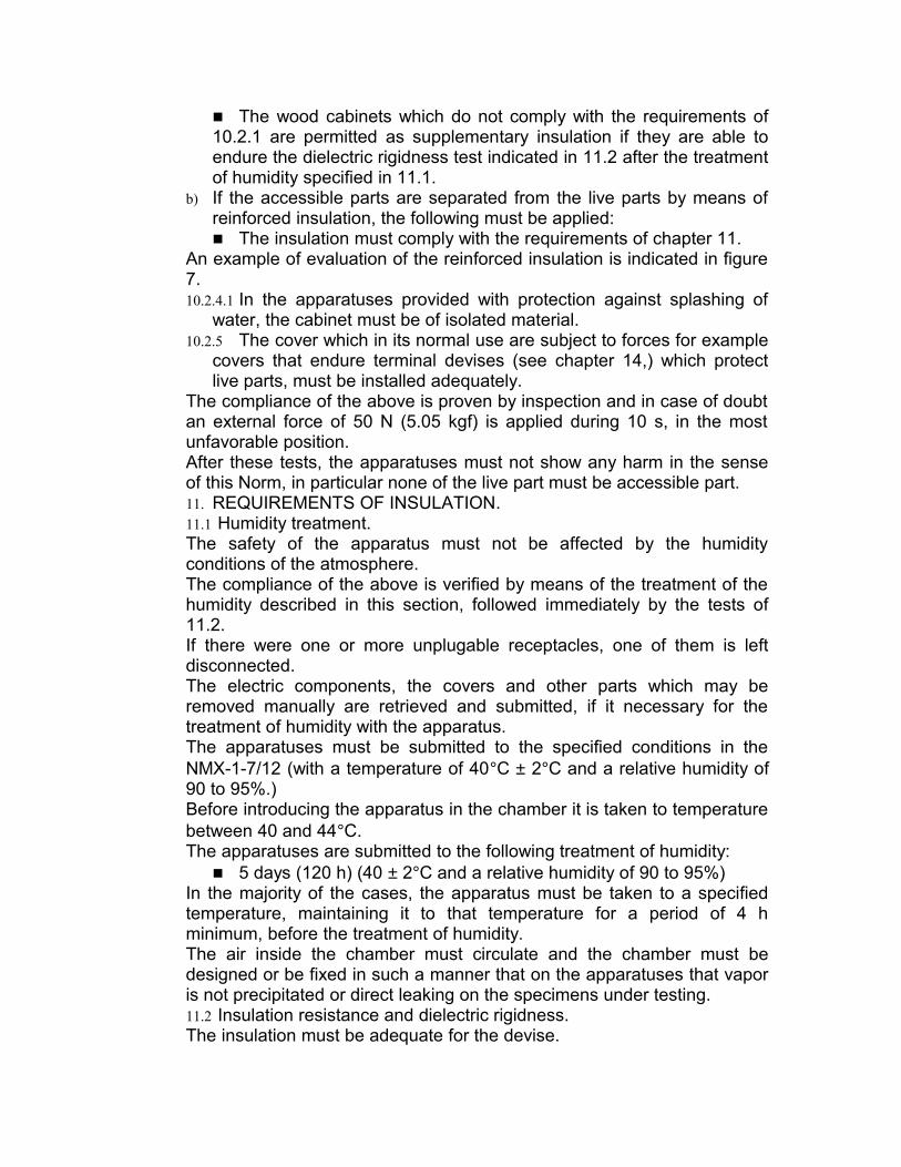
The wood cabinets which do not comply with the requirements of 10.2.1 are permitted as supplementary insulation if they are able to endure the dielectric rigidness test indicated in 11.2 after the treatment of humidity specified in 11.1.
b) If the accessible parts are separated from the live parts by means of reinforced insulation, the following must be applied: The insulation must comply with the requirements of chapter 11.
An example of evaluation of the reinforced insulation is indicated in figure 7.10.2.4.1 In the apparatuses provided with protection against splashing of
water, the cabinet must be of isolated material.10.2.5 The cover which in its normal use are subject to forces for example
covers that endure terminal devises (see chapter 14,) which protect live parts, must be installed adequately.
The compliance of the above is proven by inspection and in case of doubt an external force of 50 N (5.05 kgf) is applied during 10 s, in the most unfavorable position.After these tests, the apparatuses must not show any harm in the sense of this Norm, in particular none of the live part must be accessible part.11. REQUIREMENTS OF INSULATION.11.1 Humidity treatment.The safety of the apparatus must not be affected by the humidity conditions of the atmosphere.The compliance of the above is verified by means of the treatment of the humidity described in this section, followed immediately by the tests of 11.2.If there were one or more unplugable receptacles, one of them is left disconnected.The electric components, the covers and other parts which may be removed manually are retrieved and submitted, if it necessary for the treatment of humidity with the apparatus.The apparatuses must be submitted to the specified conditions in the NMX-1-7/12 (with a temperature of 40°C ± 2°C and a relative humidity of 90 to 95%.)Before introducing the apparatus in the chamber it is taken to temperature between 40 and 44°C.The apparatuses are submitted to the following treatment of humidity:
5 days (120 h) (40 ± 2°C and a relative humidity of 90 to 95%)In the majority of the cases, the apparatus must be taken to a specified temperature, maintaining it to that temperature for a period of 4 h minimum, before the treatment of humidity.The air inside the chamber must circulate and the chamber must be designed or be fixed in such a manner that on the apparatuses that vapor is not precipitated or direct leaking on the specimens under testing.11.2 Insulation resistance and dielectric rigidness.The insulation must be adequate for the devise.
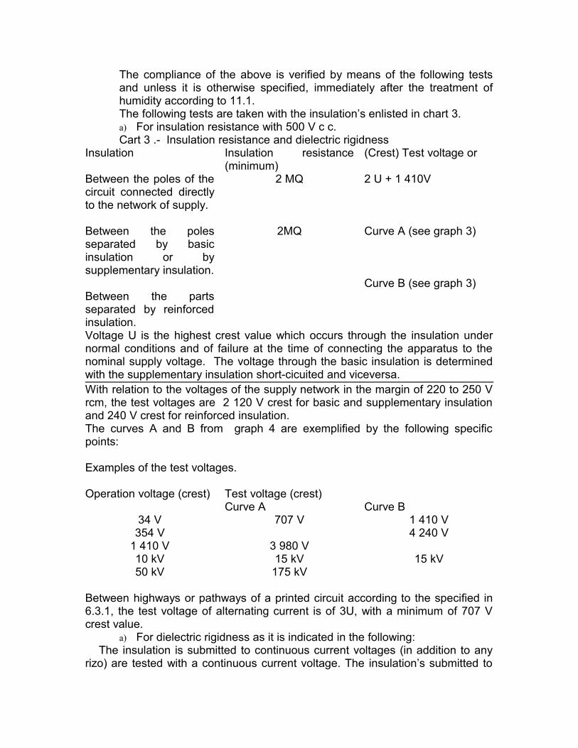
The compliance of the above is verified by means of the following tests and unless it is otherwise specified, immediately after the treatment of humidity according to 11.1.The following tests are taken with the insulation’s enlisted in chart 3.a) For insulation resistance with 500 V c c.Cart 3 .- Insulation resistance and dielectric rigidness
Insulation Insulation resistance (minimum)
(Crest) Test voltage or
Between the poles of the circuit connected directly to the network of supply.
Between the poles separated by basic insulation or by supplementary insulation.
Between the parts separated by reinforced insulation.
2 MQ
2MQ
2 U + 1 410V
Curve A (see graph 3)
Curve B (see graph 3)
Voltage U is the highest crest value which occurs through the insulation under normal conditions and of failure at the time of connecting the apparatus to the nominal supply voltage. The voltage through the basic insulation is determined with the supplementary insulation short-cicuited and viceversa.With relation to the voltages of the supply network in the margin of 220 to 250 V rcm, the test voltages are 2 120 V crest for basic and supplementary insulation and 240 V crest for reinforced insulation.The curves A and B from graph 4 are exemplified by the following specific points:
Examples of the test voltages.
Operation voltage (crest) Test voltage (crest)
34 V354 V
1 410 V10 kV50 kV
Curve A707 V
3 980 V15 kV175 kV
Curve B1 410 V4 240 V
15 kV
Between highways or pathways of a printed circuit according to the specified in 6.3.1, the test voltage of alternating current is of 3U, with a minimum of 707 V crest value.
a) For dielectric rigidness as it is indicated in the following:The insulation is submitted to continuous current voltages (in addition to any
rizo) are tested with a continuous current voltage. The insulation’s submitted to

alternating current voltage, are tested with an alternating current voltage, to the frequency of the supply network for which they were designed. When crown effects occur, of load, ionization or similar, a continuous current voltage test is recommended, the testing voltages are applied for 1 min.
The measures during the insulation resistance and dielectric test are done in the humidity chamber of in the room in which the apparatuses were taken to the prescribed temperature, one the parts which had been taken away have been placed again.
It is considered that the apparatus complies with the requirements if the insulation resistance measured after 1 min if is not less than the values given in chart 3 and if there were no disruptive discharges by dielectric or perforation effects, during the dielectric rigidness test.
When wrappings of isolation materials are tested, it is intimately pressured against the accessible parts or external wrappings, a metallic sheet (aluminum or foil) which is utilized as a point of power application and measure.The test is not taken with insulation which at the time of short-circuit do not provoke any danger of electric shock, for example in the case in which a terminal of a secondary spool of a supply transformer is connected to an accessible metallic part, the other terminal does not need to comply with any requirement of special insulation, with relation to the same accessible metallic part.
The accessible metallic parts may be interconnected during the dielectric rigidness test.
The resistor capacitors and any other reactive element which comply with the sections indicated in this Norm connected in parallel with the insulation’s which will be tested, must be disconnected.The outlets which suminister supply of the electric network to other apparatuses and marked terminals with the symbol according with section 7.4 b,) they are not submitted to the tests mentioned in lines 2 and 3 on chart 3.
In the case in which the spools of a transformer drive a current to the frequency of the network of supply and are not connected to a terminal devise of test, and the dielectric rigidness test, does not result possible due to a spool terminal being connector to the lamination, to an adjacent spool or similar.
12. MECHANICL ROBUSTNESS.The apparatus must have adequate mechanical robustness, and must be designed and constructed in such a manner that they are able to withstand the management expected at normal use, without its safety being compromised.The compliance of the above is verified taking the following indicated tests: 12.1 Hitting test.The apparatus is placed upon a horizontal support made of wood which purpose it is to prevent direct impacts of the cabinet and is dropped 50 times from a height of 5 cm over the wood table.After this test alterations must not manifest of the safety conditions established by this Norm in the sense that they could have failed in terms

of its operative characteristics, but its safety conditions must not have been left affected.12.2 Setting of control devises.Knobs, handles, pressure keys and similar control devises must be constructed and set in such a manner that their use does not jeopardize the protection against electrical shock.The compliance of the indicated must be proven by means of the following tests described.12.2.1 The control devises must then be subjected, during 1 min, to the
corresponding couple at a force of 100 N (10.2 kgf.) If the mass of the apparatus is less than 10 kg, the traction force must be limited to the corresponding value to the mass of the apparatus itself, but it must not be less than 25 N (2.55 kgf.)12.2.2 For the control devises such as pressure keys and similar on which
a pressure is only executed during its normal use and that it does not outstand more than 15 mm from the surface of the apparatus, the traction force is reduced 50 N (5.1 kgf.)
12.2.3 After these tests the apparatus must not show alterations of the safety conditions established by this Norm, and in particular none of the live parts must turn accessible when retrieved with the traction force established, a knob, manija, handle, pressure key and control devise.
12.3 Drawers.The drawers which are designed to be partially pulled outside must have an adequate mechanical resistance top to prevent that the live parts come to be accessible.The compliance of the indicated is verified by means of the following test:The drawer is pulled in normal manner until the output top limit then a force of 50 N (5.1 kgf) is applied during 10 s in the most unfavorable direction.After the test, the apparatus must not show alterations of the safety conditions established by this Norm and in particular none of the live part must turn accessible.13. COMPONENTS ENVOLVED IN SAFETY.13.1 Pilas, batteries and their compartments.The compartment covers or pilas receptacles or batteries fastened by screws, must be equipped with screws of captive type which permit the retrieval of the cover without becoming loose or getting lost.The compartments with the pilas and batteries must be designed in such a manner that there exists no risks of accumulation of inflammable gases in the interior of the apparatus.The apparatuses which include in their interior of its cabinet pilas or batteries with electrolyte liquid must be designed and manufactured in such a manner that the insulation may not be affected by an eventual leak or spill of the batteries.

The compliance of the specified above is verified by means of visual inspection.14. TERMINAL DEVISES.14.1 Clavijas, outlets and contacts.14.1.1 The clavijas and the connector devises for the connection of the
apparatus to the network and the outlets to provide network voltage to other apparatuses, must comply with the specifications given for fixed outlets and connector devises for household purpose apparatuses.
14.1.2 The connectors for antenna and tierra and for input and output transducers of audio and video, must be designed in such a manner that: The connectors may not have permanent connection with the contacts of a network outlet not even in one of its terminals, or The connectors which have such a form that they may not be inserted in a network outlet.
The receptacles for the output transducers of audio and video made according to 7.4.2, must be designed in such a manner that any conductor for antenna and tierra and for load transducers of audio and video circuits as well as transducer sources may not be inserted into them,15. CABLES AND EXTRIOR FLEXIBLE CORDS.15.1 In general, the cables and supply cords of the apparatus must satisfy
the following requirements:The surface of transversal section of each one of the conductors must not be inferior than 0.75 mm². 15.2 Conductors of flexible cords utilized as connection between the
apparatus and other apparatuses used in combination with it, must have a transversal straight section so that the elevation of temperature of the insulation under normal conditions of operation and under failure conditions be depreciable.
15.3 The compliance with the above indicated is verified by means of visual inspection, in case of doubt, the elevations of temperature of the insulation are determined under normal conditions of operation, as well as under failure conditions, the elevation of temperature must not exceed the values given in the corresponding columns of chart 2.
16. ELECTRIC CONNECTIONS AND MECHANICAL SETTINGS.16.1 The screw or terminal connections which are utilized as electric
contact and the terminals and screw contacts which during the life of the apparatus are exposed to being loosened and fastened various times, must have an adequate mechanical robustness.
The screws that execute contact by pressure and the screws with a diameter less than 3 mm and which form part of the settings of screws mentioned previously, must be screwed on a metallic bolt or on a metallic insert.

The screws with a diameter inferior to 3 mm which execute no contact by pressure are excluded, they do not require a metallic insert but must support the torsional couple specified in chart 4 related to 3 mm screws.Some examples of screws which during the life of the apparatus are loosened and fastened various times are the terminal screws, the setting screws for covers (only when these must be loosened to open the appears,) the screws and prisoners to set handles, knobs and similar.The compliance with the indicated above is verified by the following test:The screws are loosened and fastened with a torsional couple according to chart 4:
five times in the case that the screws which operate in a machueleado made in metal. ten times in the case that the screws which operate in a machueleado made in wood or any other insulation material.
In the last case, the screws must be completely taken off or reinserted in each occasion.The screws must not be fastened with rough movements. After the test, there must not be any harm which lessen the safety of the apparatus.The material in which the screws are inserted is verified by visual exam.
Chart 4.- Torsional couple applied to the screws.
Diameter of the Torsional couple Nm (kgf. cm) screw mm
Screws with Screws without head head or prisoners
2.5 0.4 ( 4 ) 0.20 (2.0) 3.0 0.5 ( 5 ) 0.25 (2.5) 3.5 0.8 ( 8 ) 0.40 (4.0) 4.0 1.2 ( 12 ) 0.70 (7.0) 5.0 2.0 ( 20 ) 0.70 (7.0) 6.0 2.5 ( 25 ) - - - - - - -
16.2 The necessary means must be provided to insure the correct introduction of the screws in machueleados made in non-metallic materials, if the screws will be loosened and fastened various times during the life of the apparatus, being able to affect the safety of itself.
The compliance with the previously indicated is proven by visual exam and manual test.Note.- This requirement is complied if an introduction in an inclined manner is avoided, for example, guiding the screw in the part to be set.16.3 The electric connections in parts which are directly connected to the
network (see 4.9,) must be designed in such a manner that the

pressure of contact is not transmitted through insulation materials which are not ceramic. Unless there is sufficient capacity in the metallic parts which compensate any contraction of insulation material.
The compliance with the indicated previously is proven by visual exam.16.4 Other cover setting devises which are not screws, which may be
operated during the useful life of the apparatus, must have adequate mechanical rigidness, if the failure of such devises deteriorate the safety of the apparatus.
16.5 The positions of fastening and loosening these devises must not be ambiguous, and must not be possible that without a warning, the devise is loosened.
The compliance of the indicated is verified by visual exam, by operation of the devise and by one of the following tests:
In case the devises which operation is affected by a combination of lineal and rotation movements which fasten it and loosen it, the torsional couples or necessary forces are measured for this operation. With the devise in the fastened position it is applied in the sense to fasten a couple or force double the necessary value to fasten the devise, with a minute of 1 Nm (10 kgf.cm) or 10 N (1 kgf,) except that it loosens by a small couple or force in the same direction of fastened.
This operation is executed ten times.The couple of force necessary to loosen the devise must be at least of 0.1 Nm (1.02 kgf.cm) or 1 N (0.102 kgf.)
In the case of fixed covers with pressure setters, the cover is removed and it is replaced ten times, in the manner in which it is designed.
After this test, the cover must comply with the rigid finger test and test hook specified in 10.2.16.6 The dismountable legs or pedestals provided by the manufacturer,
must be integrated with the corresponding fixed screws unless they come assembled with the apparatus.
The compliance with the indicated above is verified by visual inspection.17. MECHANICAL STABILITY.The apparatuses designed to be placed on the floor and which mass exceeds the 20 kg, must have adequate mechanical stability.The compliance of the above is verified by means of the tests indicated in 17.1 and 17.2.The apparatuses provided with dismountable legs are tested installing them over their protection devises.During this test the apparatuses must not lose their equilibrium.17.1 The apparatus is placed in its position of normal use on an inclined
plain of non-sliding material with an angle of 10° with relation to the horizontal and is turned slowly in an angle of 360° around its vertical axis.
When the apparatus for its construction may balance with angle of 10° in front of the normal protection position, then it is placed on a horizontal

plain, but unbalancing it in an angle of 10° in the most unfavorable direction.Note.- This test upon a horizontal protection may be needed and convenient for apparatuses provided of small legs, tops, wheel-barrows or similar devises.17.2 The apparatus is placed on a non-sliding surface which is at an angle
which does not exceed 10° with relation to the horizontal and the eventual covers, drawers, and doors are open until placing them in the most unfavorable position.
A force of 100 N (10kgf) is applied directed downward in a vertical manner in such a manner that it produces the maximum overturn motor-couple, in any point on any of any horizontal surface, protuberance or hallow space, making sure that the distance of that point to the floor does not exceed 75 cm.18. IONIZING RADIATION 18.1 The apparatuses which operate with potentials above 16 Kv (crest) in
one or more of its circuits may be dangerous sources of ionizing radiation and must be designed and manufactured in such a manner that the maximum dose emitted does not surpass the found value as acceptable in part of the I.C.R.P. (International Commission for Radiology Protection.)
18.2 The television apparatuses which operate under the conditions mentioned before must be designed and manufactured in such a manner that the ionizing radiation emitted does not surpass the value of 36 pA/kg (0.5mR/h,)