
School of Civil Engineering Sydney NSW 2006 AUSTRALIA http ...
Department of Civil Engineering
Sydney, NSW 2006
AUSTRALIAhttp://www.civil.usyd.edu.au/
Centre for Advanced Structural Engineering
Strength of Welded T-Joint TrussConnections between Equal WidthCold-Formed RHS
Research Report No R831
Lip H. Teh BE PhD
Kim J. R. Rasmussen MScEng PhD
Department of Civil EngineeringCentre for Advanced Structural Engineering
http://www.civil.usyd.edu.au/
Strength of Welded T-Joint Truss Connections between EqualWidth Cold-Formed RHS
Research Report No R831
Lip H. Teh BE, PhDKim J. R. Rasmussen, MScEng, PhD
August 2003
Abstract:
The report describes laboratory tests of arc welded T-joints between equal width rectangular
hollow sections. The brace and chord members were cold formed with a nominal yield stress
of 350 MPa. The welds were laid using MMAW and GMAW processes without profiling the
brace ends. The brace of each specimen was loaded in tension to failure with the chord
supported continuously so as not to induce significant bending effects.
The test results showed that the joint strength can be improved by using backing strips for the
butt welds, while backing rods (or filler rods) should not be used as they led to larger
variation in joint strengths, and often, inferior strengths. The test strengths are compared with
the design strengths obtained using the IIW Recommendations and Eurocode3, Part 1.8. It is
shown that for cold-formed tubes with a nominal yield stress of 350 MPa (or above), a design
check on the strength of the butt (or groove) weld is required in addition to the checks on the
strengths of the chord and brace members specified in the current design guidelines. An
equation is proposed for calculating the strength of the weld.
Keywords: butt weld, brace-to-chord connection, cold-formed steel, metal arc welding,rectangular hollow section, T-joint design
Strength of Welded T-Joint Truss Connections between Equal Width Cold-Formed RHS August 2003
Department of Civil EngineeringResearch Report No R831
2 The University of Sydney
Copyright Notice
Department of Civil Engineering, Research Report R831Strength of Welded T-Joint Truss Connections between Equal Width Cold-formed RHS
© 2003 Lip H. Teh and Kim J. R. [email protected]@civil.usyd.edu.au
This publication may be redistributed freely in its entirety and in its originalform without the consent of the copyright owner.
Use of material contained in this publication in any other published works mustbe appropriately referenced, and, if necessary, permission sought from theauthor.
Published by:Department of Civil EngineeringThe University of SydneySydney NSW 2006AUSTRALIA
August 2003
This report and other Research Reports published by The Department of CivilEngineering are available on the Internet:
http://www.civil.usyd.edu.au
Strength of Welded T-Joint Truss Connections between Equal Width Cold-Formed RHS August 2003
Department of Civil EngineeringResearch Report No R831
3 The University of Sydney
Table of Contents
1 Introduction ..................................................................................................... 4
2 Design equations to be checked ...................................................................... 6
3 Specimen configurations and joint preparations ............................................. 8
4 Material properties of RHS and welding electrodes ....................................... 9
5 Laboratory test set-up .................................................................................... 11
6 Test results of Configuration A specimens ................................................... 12
7 Test results of Configuration B specimens….……………………………...15
8 Conclusions……………………………...….……………………………...18
9 References..……………………………...….……………………………...19
Appendix I Measuring average thickness of butt welds…………..………...….21
Appendix II Welding procedures………………………………………………22
Strength of Welded T-Joint Truss Connections between Equal Width Cold-Formed RHS August 2003
Department of Civil EngineeringResearch Report No R831
4 The University of Sydney
1 Introduction
Rectangular hollow sections (which include square hollow sections) have not been used asstructural steel members for as long as open sections or even circular hollow sections. Theirindustrial production started as late as 1959 in England (Packer et al. 1992). Among theearliest design recommendations for welded connections between rectangular hollow sections(RHS) are those proposed by Eastwood & Wood (1970a, 1970b). Since then, the productionmethods of structural steel RHS have changed from hot-forming a round section then“squaring” it into shape to cold-forming the RHS, which significantly alters the materialresponse characteristics to loading stress and welding heat input. In addition, new steelmaterials such as stainless steel and in-line galvanised steel that may have unique stress-straincurves are continually being introduced to the construction market in order to achieve higherstrength per tonnage or to provide ambient-resistant structural steel members.
Many current design equations are only valid for the tubular sections which have materialproperties and/or dimension ratios similar to those of the specimens used in the experimentalverification of the relevant equations. Therefore, although research and design standards forstatically loaded 2D truss welded connections between tubular sections (IIW 1989, Packer etal. 1992, Syam & Chapman 1996, Packer & Henderson 1997, AWS 2000) are considered bysome authorities to have reached a mature state (Packer 2000), there is an on-going need forapplied research on the behaviour and strength of such connections between rectangularhollow sections which have material properties or dimension ratios not considered in thecurrent standards.
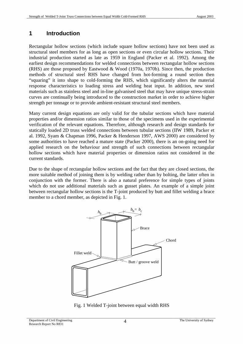
Due to the shape of rectangular hollow sections and the fact that they are closed sections, themore suitable method of joining them is by welding rather than by bolting, the latter often inconjunction with the former. There is also a natural preference for simple types of jointswhich do not use additional materials such as gusset plates. An example of a simple jointbetween rectangular hollow sections is the T-joint produced by butt and fillet welding a bracemember to a chord member, as depicted in Fig. 1.
Fig. 1 Welded T-joint between equal width RHS
Brace
Chord
Butt / groove weld
Fillet weld
hbbb bc=
Strength of Welded T-Joint Truss Connections between Equal Width Cold-Formed RHS August 2003
Department of Civil EngineeringResearch Report No R831
5 The University of Sydney
Recently, arc welded brace-to-chord connections between RHS of equal widths were removedfrom the list of pre-qualified full penetration joint configurations specified in the Australianwelding standard AS/NZS 1554.1 (SA/SNZ 2000). In Australia, all RHS are now produced bythe cold-forming technique which often results in larger corner radii and higher yield stressesthan those of hot-rolled RHS. It was deemed that the rounded corners of cold-formed RHSmight result in reduced strength of the butt welded connections due to excessive root gapswhich prevent the formation of full butt welds, unless the connected end of the brace isprofiled to fit the rounded corners of the chord. However, it has been demonstrated by Teh &Rasmussen (2002) that arc welded brace-to-chord connections between equal width cold-formed RHS can be pre-qualified subject to certain conditions, and a recommendation hasbeen made to the relevant committee for the inclusion of such connections in AS/NZS1554.1in the list of pre-qualified joint configurations for full penetration butt weld. Therecommendation was based on tensile tests and macro inspections of coupons cut from thesidewalls of the brace and chord of welded T-joints.
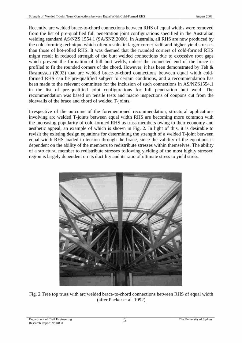
Irrespective of the outcome of the forementioned recommendation, structural applicationsinvolving arc welded T-joints between equal width RHS are becoming more common withthe increasing popularity of cold-formed RHS as truss members owing to their economy andaesthetic appeal, an example of which is shown in Fig. 2. In light of this, it is desirable torevisit the existing design equations for determining the strength of a welded T-joint betweenequal width RHS loaded in tension through the brace, since the validity of the equations isdependent on the ability of the members to redistribute stresses within themselves. The abilityof a structural member to redistribute stresses following yielding of the most highly stressedregion is largely dependent on its ductility and its ratio of ultimate stress to yield stress.
Fig. 2 Tree top truss with arc welded brace-to-chord connections between RHS of equal width(after Packer et al. 1992)

Strength of Welded T-Joint Truss Connections between Equal Width Cold-Formed RHS August 2003
Department of Civil EngineeringResearch Report No R831
6 The University of Sydney
Research on the behaviour and strength of welded T-joints between equal width hot-formedand cold-formed RHS having a nominal yield stress of 240 MPa was previously conducted byWardenier & de Koning (1974). It was concluded that the manufacturing technique (and thewelding process) did not significantly affect the behaviour and strength of the testedspecimens. However, the ductility and the ratio of ultimate stress to yield stress of more recentcold-formed steels, especially those of grade C350 or C450 (with a nominal yield stress of350 MPa or 450 MPa, respectively) manufactured to AS 1163 (SA 1991a), are considerablyless than those of a hot-rolled steel or a cold-formed steel of grade C250. While the currentinternational design equations are believed by some authorities to be generally conservative oreven excessively conservative (Kurobane 2002), in the present case the opposite may be true.In recognition of the fact that most previous tests on welded joints were undertaken on“ordinary” steel grades, current design guidelines (IIW 1989, Packer et al 1992) require thatthe yield stress of the tubes not exceed 355 MPa and 0.8 times the ultimate tensile strength. InPart 1.8 of the Eurocode3 draft (CEN 2002), the resistance of a welded hollow section joint isreduced by 10% if the tubes are of steel grade S420 or S460, and the yield stress may notexceed 460 MPa.
This report describes the experimental test results of welded T-joints between equal widthcold-formed RHS of grade C350 manufactured by OneSteel Market Mills, Pipe & Tube,Newcastle. The joints were fabricated using Manual Metal Arc Welding (MMAW) and GasMetal Arc Welding (GMAW) processes with various joint preparations, and were tested tofailure by applying tension loads to the brace members. The test set-up was such that each T-joint was required to resist essentially only the brace axial load, i.e. the T-joint was assumedto be a truss connection rather than a moment connection. The ultimate loads obtained fromthe laboratory tests are used to check the design equations found in Packer et al. (1992) andSyam & Chapman (1996), which are based on the experimental test results obtained byDavies et al. (1981) for hot-formed RHS having a nominal yield stress of 255 MPa. Theseexisting design equations are given in the following section. Based on the present test results,a design check on the weld strength is proposed.
2 Design equations to be checked
Assuming the welds are satisfactory, the design capacity of a welded T-joint between equalwidth RHS loaded in tension through the brace is controlled by either “chord side wallfailure”
( )cbcycsw 102 thtfN +=φ (1)
in which
fyc = chord yield stress;
tc = chord wall thickness;
hb = brace width parallel to the chord side wall;
or “brace yielding”
( )ebbbybb 242 bthtfN +−=φ (2)
Strength of Welded T-Joint Truss Connections between Equal Width Cold-Formed RHS August 2003
Department of Civil EngineeringResearch Report No R831
7 The University of Sydney
in which
fyb = brace yield stress;
tb = brace wall thickness;
bbbyb
cyc
cce /
10bb
tf
tf
tbb ≤= (3)
where
bc = width of chord face;
bb = brace width across the chord face = bc.
Equations (1) through (3) are given by Packer et al. (1992), and are adopted by Syam &Chapman (1996). The capacity factor φ implicit in Equations (1) and (2) is 0.9. Thedimensions of the brace and the chord are defined in Fig. 1.
It is of interest to note that Eurocode 3 (CEN 1992) requires that the throat thickness of a filletweld in a tubular T-joint be at least 10% greater than the wall thickness of the brace.However, such a requirement is largely immaterial to a T-joint between equal width RHS asin most cases the brace load is mostly resisted by the butt welds rather than the fillet welds. Inthis regard, Teh & Rasmussen (2002) have demonstrated that complete penetration butt weldsbetween equal width RHS can be achieved under certain conditions.
Frater & Packer (1992a, 1992b) made some recommendations for the effective length of filletwelds in gapped and overlapped K-joints between RHS of unequal widths. Theirrecommendations have been extrapolated to other tubular joints including T-joints in somedesign guides (Packer et al. 1992). More recently, Packer & Cassidy (1995) conductedlaboratory tests on T-joints between RHS of unequal widths and recommended that theeffective length of the fillet welds around the brace in a T-joint is
bw 2hl = (4)
Assuming Equation (4) is also valid for the effective length of the butt welds in a T-jointbetween equal width RHS, and considering the coupon test results reported by Teh &Rasmussen (2002), the nominal capacity of the butt welds in a such a joint is
bbuw 2htfVw = (5)
in which fuw is the nominal tensile strength of the weld metal.
In this report, all the above design equations are checked against laboratory test results, usingthe measured values of the design variables. The brace wall thickness tb in Equation (5) isreplaced with the average throat thickness of the butt welds, av,wt , measured in the manner
described in Appendix I. The predicted capacity of the butt weld is then
bav,uw 2htfV ww = (6)
in which av,wt is taken as tb in the case of oversize welds where tw,av exceeds tb.
Strength of Welded T-Joint Truss Connections between Equal Width Cold-Formed RHS August 2003
Department of Civil EngineeringResearch Report No R831
8 The University of Sydney
3 Specimen configurations and joint preparations
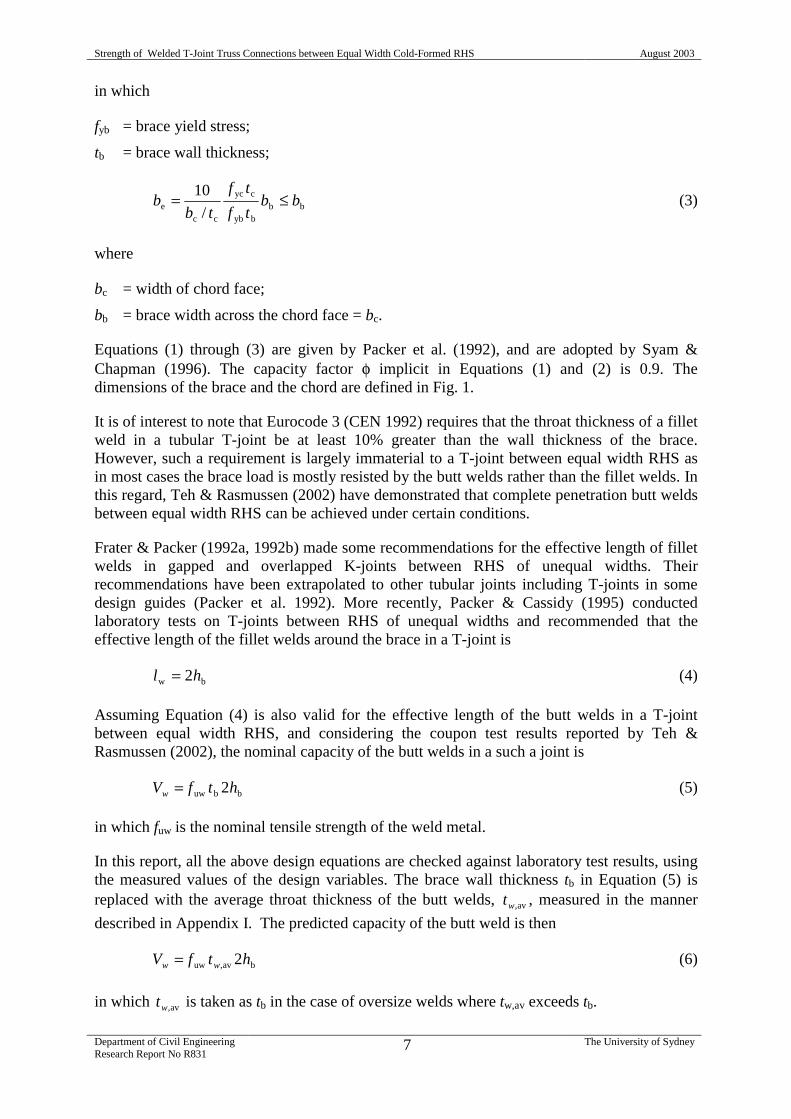
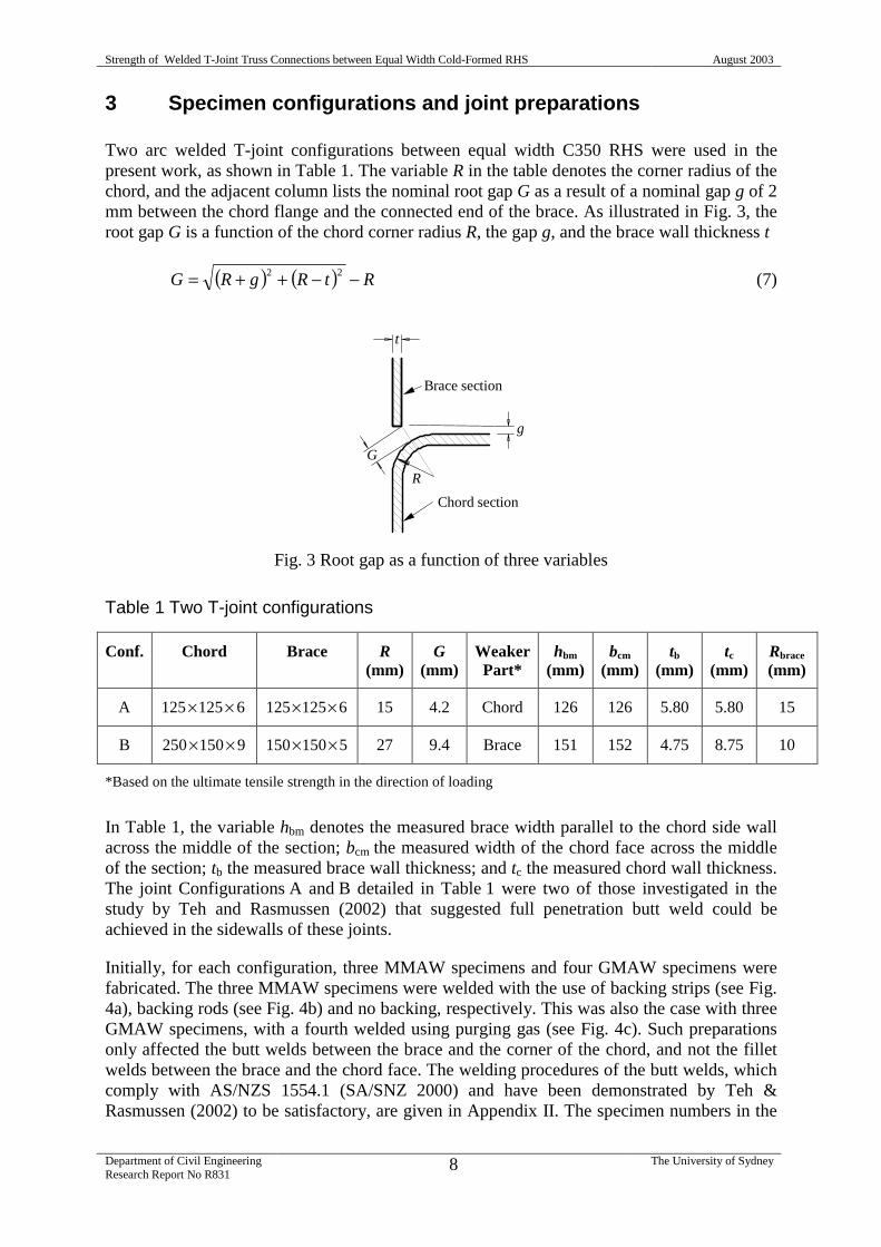
Two arc welded T-joint configurations between equal width C350 RHS were used in thepresent work, as shown in Table 1. The variable R in the table denotes the corner radius of thechord, and the adjacent column lists the nominal root gap G as a result of a nominal gap g of 2mm between the chord flange and the connected end of the brace. As illustrated in Fig. 3, theroot gap G is a function of the chord corner radius R, the gap g, and the brace wall thickness t
( ) ( ) RtRgRG −−++= 22 (7)
Fig. 3 Root gap as a function of three variables
Table 1 Two T-joint configurations
Conf. Chord Brace R(mm)
G(mm)
WeakerPart*
hbm
(mm)bcm
(mm)tb
(mm)tc
(mm)Rbrace
(mm)
A 6125125 ×× 6125125 ×× 15 4.2 Chord 126 126 5.80 5.80 15
B 9150250 ×× 5150150 ×× 27 9.4 Brace 151 152 4.75 8.75 10
*Based on the ultimate tensile strength in the direction of loading
In Table 1, the variable hbm denotes the measured brace width parallel to the chord side wallacross the middle of the section; bcm the measured width of the chord face across the middleof the section; tb the measured brace wall thickness; and tc the measured chord wall thickness.The joint Configurations A and B detailed in Table 1 were two of those investigated in thestudy by Teh and Rasmussen (2002) that suggested full penetration butt weld could beachieved in the sidewalls of these joints.
Initially, for each configuration, three MMAW specimens and four GMAW specimens werefabricated. The three MMAW specimens were welded with the use of backing strips (see Fig.4a), backing rods (see Fig. 4b) and no backing, respectively. This was also the case with threeGMAW specimens, with a fourth welded using purging gas (see Fig. 4c). Such preparationsonly affected the butt welds between the brace and the corner of the chord, and not the filletwelds between the brace and the chord face. The welding procedures of the butt welds, whichcomply with AS/NZS 1554.1 (SA/SNZ 2000) and have been demonstrated by Teh &Rasmussen (2002) to be satisfactory, are given in Appendix II. The specimen numbers in the
R
Brace section
Chord section
G
g
t
Strength of Welded T-Joint Truss Connections between Equal Width Cold-Formed RHS August 2003
Department of Civil EngineeringResearch Report No R831
9 The University of Sydney
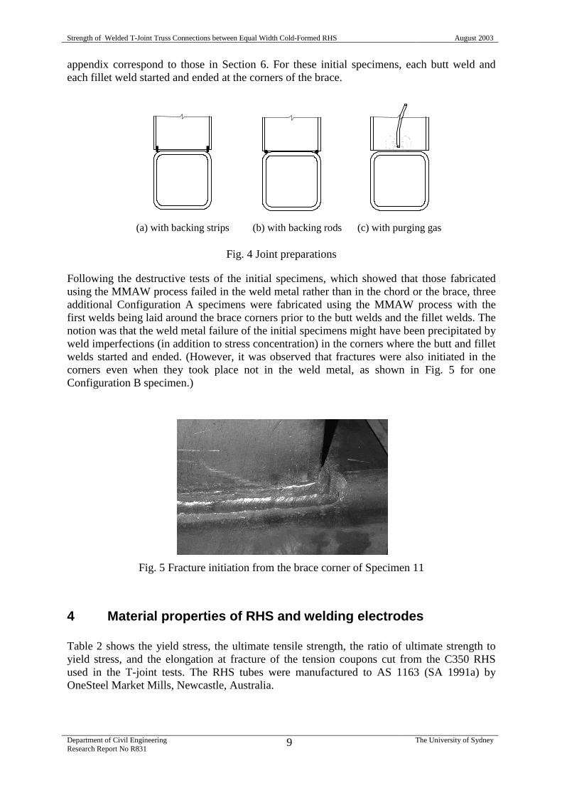
appendix correspond to those in Section 6. For these initial specimens, each butt weld andeach fillet weld started and ended at the corners of the brace.
Fig. 4 Joint preparations
Following the destructive tests of the initial specimens, which showed that those fabricatedusing the MMAW process failed in the weld metal rather than in the chord or the brace, threeadditional Configuration A specimens were fabricated using the MMAW process with thefirst welds being laid around the brace corners prior to the butt welds and the fillet welds. Thenotion was that the weld metal failure of the initial specimens might have been precipitated byweld imperfections (in addition to stress concentration) in the corners where the butt and filletwelds started and ended. (However, it was observed that fractures were also initiated in thecorners even when they took place not in the weld metal, as shown in Fig. 5 for oneConfiguration B specimen.)
Fig. 5 Fracture initiation from the brace corner of Specimen 11
4 Material properties of RHS and welding electrodes
Table 2 shows the yield stress, the ultimate tensile strength, the ratio of ultimate strength toyield stress, and the elongation at fracture of the tension coupons cut from the C350 RHSused in the T-joint tests. The RHS tubes were manufactured to AS 1163 (SA 1991a) byOneSteel Market Mills, Newcastle, Australia.
(a) with backing strips (b) with backing rods (c) with purging gas
Strength of Welded T-Joint Truss Connections between Equal Width Cold-Formed RHS August 2003
Department of Civil EngineeringResearch Report No R831
10 The University of Sydney
Table 2 Material properties of RHS specimens
Section LoadingDirection
fy
(MPa)fu
(MPa)fu/fy %
elongationGauge(mm)
6125125 ×× Longitudinal 405 485 1.20 30.9 47.5
6125125 ×× Transverse 410 475 1.16 38.4 28.5
5150150 ×× Longitudinal 375 485 1.29 30.8 42.5
5150150 ×× Transverse 375 480 1.28 32.9 42.5
9150250 ×× Longitudinal 390 455 1.16 32.5 60.0
9150250 ×× Transverse 355 445 1.25 30.2 60.0
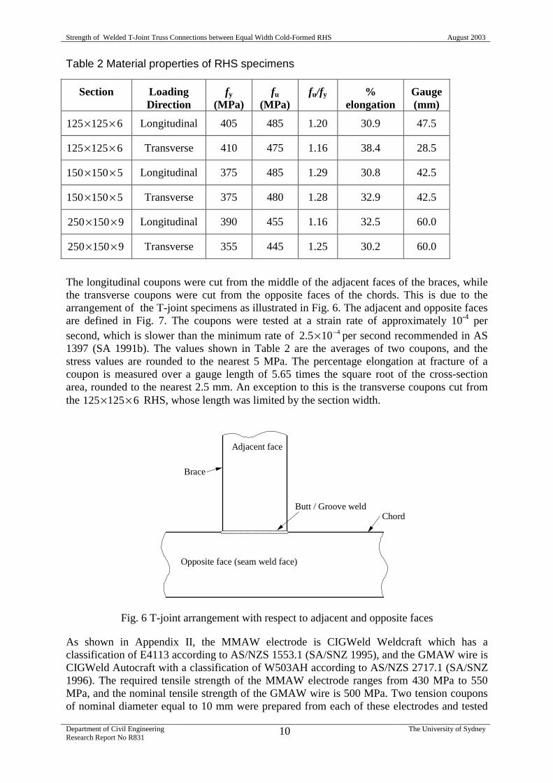
The longitudinal coupons were cut from the middle of the adjacent faces of the braces, whilethe transverse coupons were cut from the opposite faces of the chords. This is due to thearrangement of the T-joint specimens as illustrated in Fig. 6. The adjacent and opposite facesare defined in Fig. 7. The coupons were tested at a strain rate of approximately 10-4 persecond, which is slower than the minimum rate of 4105.2 −× per second recommended in AS1397 (SA 1991b). The values shown in Table 2 are the averages of two coupons, and thestress values are rounded to the nearest 5 MPa. The percentage elongation at fracture of acoupon is measured over a gauge length of 5.65 times the square root of the cross-sectionarea, rounded to the nearest 2.5 mm. An exception to this is the transverse coupons cut fromthe 6125125 ×× RHS, whose length was limited by the section width.
Fig. 6 T-joint arrangement with respect to adjacent and opposite faces
As shown in Appendix II, the MMAW electrode is CIGWeld Weldcraft which has aclassification of E4113 according to AS/NZS 1553.1 (SA/SNZ 1995), and the GMAW wire isCIGWeld Autocraft with a classification of W503AH according to AS/NZS 2717.1 (SA/SNZ1996). The required tensile strength of the MMAW electrode ranges from 430 MPa to 550MPa, and the nominal tensile strength of the GMAW wire is 500 MPa. Two tension couponsof nominal diameter equal to 10 mm were prepared from each of these electrodes and tested
Butt / Groove weldChord
Brace
Adjacent face
Opposite face (seam weld face)
Strength of Welded T-Joint Truss Connections between Equal Width Cold-Formed RHS August 2003
Department of Civil EngineeringResearch Report No R831
11 The University of Sydney
in accordance with AS 2205.2.2 (SA 2003) and AS 1391 (SA 1991b). For the MMAWelectrodes, only the 4.00 mm one was used in the tension coupon tests. The results are shownin Table 3.
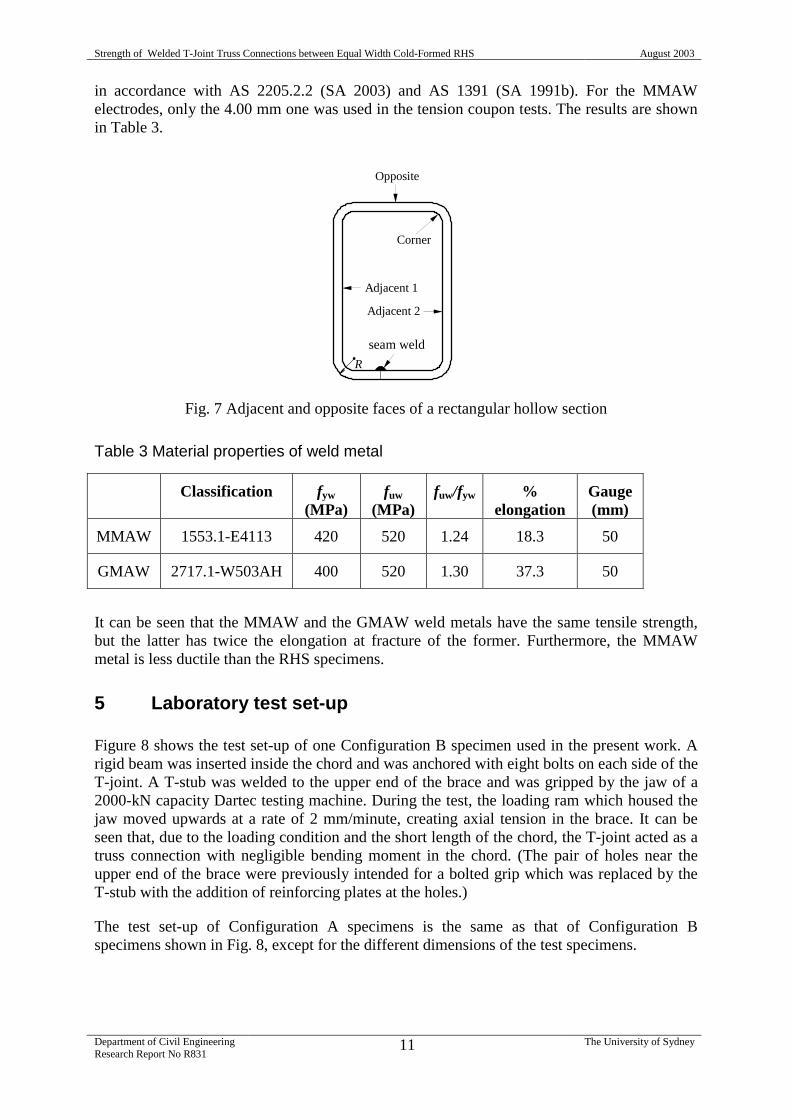
Fig. 7 Adjacent and opposite faces of a rectangular hollow section
Table 3 Material properties of weld metal
Classification fyw
(MPa)fuw
(MPa)fuw/fyw %
elongationGauge(mm)
MMAW 1553.1-E4113 420 520 1.24 18.3 50
GMAW 2717.1-W503AH 400 520 1.30 37.3 50
It can be seen that the MMAW and the GMAW weld metals have the same tensile strength,but the latter has twice the elongation at fracture of the former. Furthermore, the MMAWmetal is less ductile than the RHS specimens.
5 Laboratory test set-up
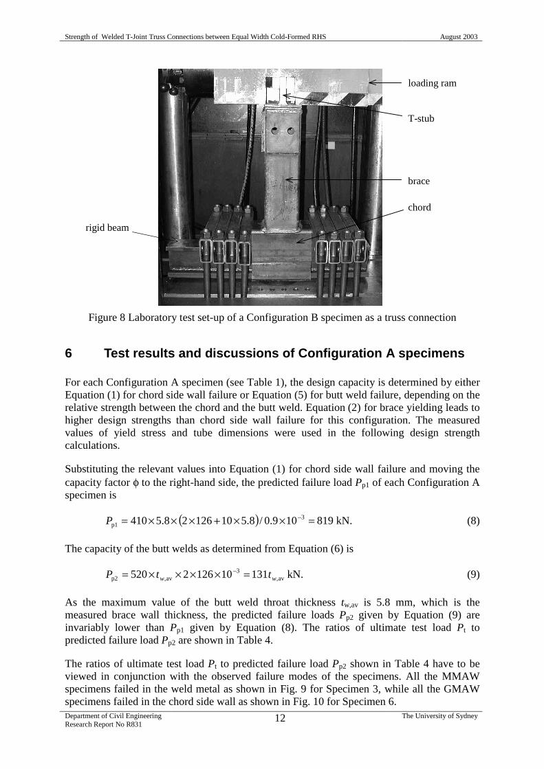
Figure 8 shows the test set-up of one Configuration B specimen used in the present work. Arigid beam was inserted inside the chord and was anchored with eight bolts on each side of theT-joint. A T-stub was welded to the upper end of the brace and was gripped by the jaw of a2000-kN capacity Dartec testing machine. During the test, the loading ram which housed thejaw moved upwards at a rate of 2 mm/minute, creating axial tension in the brace. It can beseen that, due to the loading condition and the short length of the chord, the T-joint acted as atruss connection with negligible bending moment in the chord. (The pair of holes near theupper end of the brace were previously intended for a bolted grip which was replaced by theT-stub with the addition of reinforcing plates at the holes.)
The test set-up of Configuration A specimens is the same as that of Configuration Bspecimens shown in Fig. 8, except for the different dimensions of the test specimens.
RERW
Adjacent 1
Adjacent 2
Corner
Opposite
seam weld
Strength of Welded T-Joint Truss Connections between Equal Width Cold-Formed RHS August 2003
Department of Civil EngineeringResearch Report No R831
12 The University of Sydney
Figure 8 Laboratory test set-up of a Configuration B specimen as a truss connection
6 Test results and discussions of Configuration A specimens
For each Configuration A specimen (see Table 1), the design capacity is determined by eitherEquation (1) for chord side wall failure or Equation (5) for butt weld failure, depending on therelative strength between the chord and the butt weld. Equation (2) for brace yielding leads tohigher design strengths than chord side wall failure for this configuration. The measuredvalues of yield stress and tube dimensions were used in the following design strengthcalculations.
Substituting the relevant values into Equation (1) for chord side wall failure and moving thecapacity factor φ to the right-hand side, the predicted failure load Pp1 of each Configuration Aspecimen is
( ) kN.819109.0/8.51012628.5410 3p1 =××+×××= −P (8)
The capacity of the butt welds as determined from Equation (6) is
kN.131101262520 av,3
av,p2 ww ttP =××××= − (9)
As the maximum value of the butt weld throat thickness tw,av is 5.8 mm, which is themeasured brace wall thickness, the predicted failure loads Pp2 given by Equation (9) areinvariably lower than Pp1 given by Equation (8). The ratios of ultimate test load Pt topredicted failure load Pp2 are shown in Table 4.
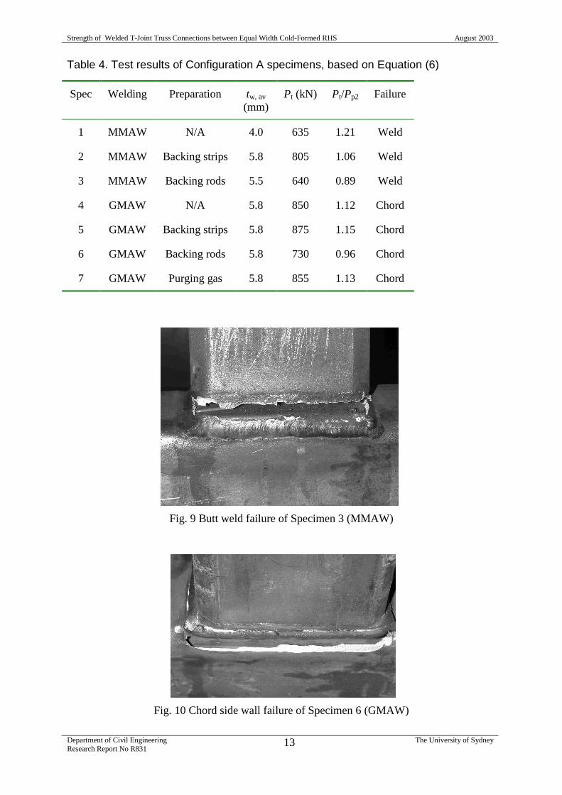
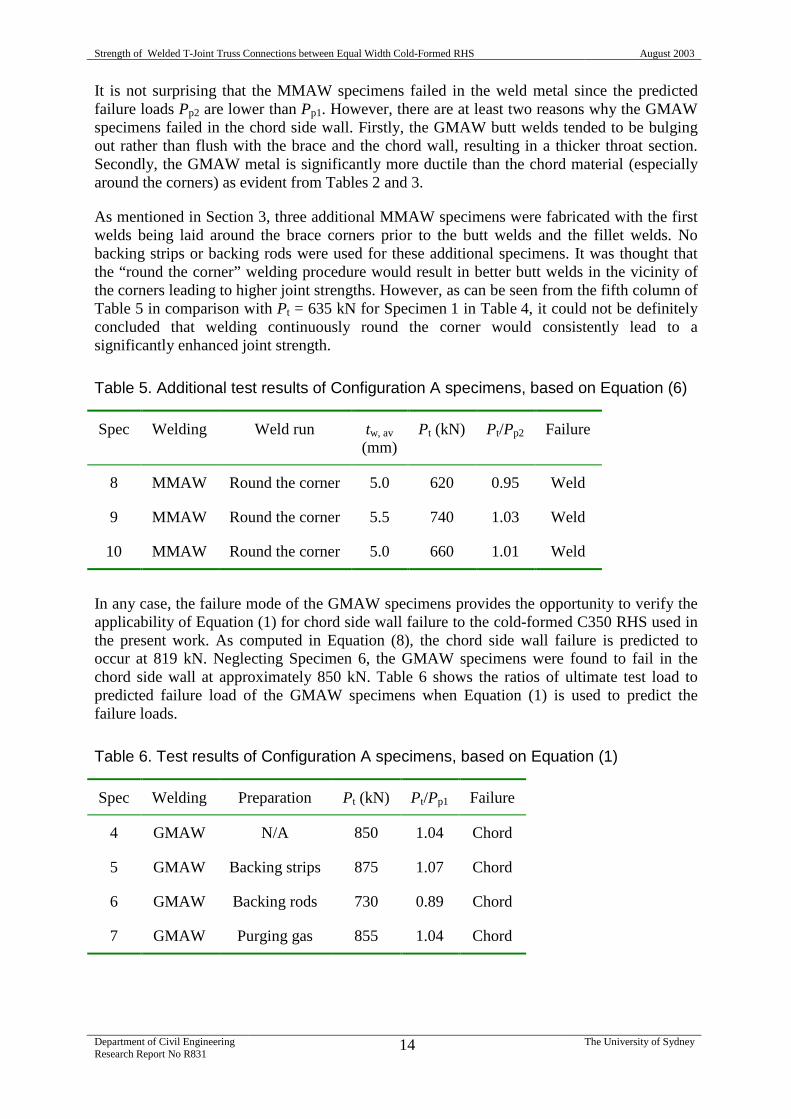
The ratios of ultimate test load Pt to predicted failure load Pp2 shown in Table 4 have to beviewed in conjunction with the observed failure modes of the specimens. All the MMAWspecimens failed in the weld metal as shown in Fig. 9 for Specimen 3, while all the GMAWspecimens failed in the chord side wall as shown in Fig. 10 for Specimen 6.
T-stub
loading ram
brace
chord
rigid beam
Strength of Welded T-Joint Truss Connections between Equal Width Cold-Formed RHS August 2003
Department of Civil EngineeringResearch Report No R831
13 The University of Sydney
Table 4. Test results of Configuration A specimens, based on Equation (6)
Spec Welding Preparation tw, av
(mm)Pt (kN) Pt/Pp2 Failure
1 MMAW N/A 4.0 635 1.21 Weld
2 MMAW Backing strips 5.8 805 1.06 Weld
3 MMAW Backing rods 5.5 640 0.89 Weld
4 GMAW N/A 5.8 850 1.12 Chord
5 GMAW Backing strips 5.8 875 1.15 Chord
6 GMAW Backing rods 5.8 730 0.96 Chord
7 GMAW Purging gas 5.8 855 1.13 Chord
Fig. 9 Butt weld failure of Specimen 3 (MMAW)
Fig. 10 Chord side wall failure of Specimen 6 (GMAW)
Strength of Welded T-Joint Truss Connections between Equal Width Cold-Formed RHS August 2003
Department of Civil EngineeringResearch Report No R831
14 The University of Sydney
It is not surprising that the MMAW specimens failed in the weld metal since the predictedfailure loads Pp2 are lower than Pp1. However, there are at least two reasons why the GMAWspecimens failed in the chord side wall. Firstly, the GMAW butt welds tended to be bulgingout rather than flush with the brace and the chord wall, resulting in a thicker throat section.Secondly, the GMAW metal is significantly more ductile than the chord material (especiallyaround the corners) as evident from Tables 2 and 3.
As mentioned in Section 3, three additional MMAW specimens were fabricated with the firstwelds being laid around the brace corners prior to the butt welds and the fillet welds. Nobacking strips or backing rods were used for these additional specimens. It was thought thatthe “round the corner” welding procedure would result in better butt welds in the vicinity ofthe corners leading to higher joint strengths. However, as can be seen from the fifth column ofTable 5 in comparison with Pt = 635 kN for Specimen 1 in Table 4, it could not be definitelyconcluded that welding continuously round the corner would consistently lead to asignificantly enhanced joint strength.
Table 5. Additional test results of Configuration A specimens, based on Equation (6)
Spec Welding Weld run tw, av
(mm)Pt (kN) Pt/Pp2 Failure
8 MMAW Round the corner 5.0 620 0.95 Weld
9 MMAW Round the corner 5.5 740 1.03 Weld
10 MMAW Round the corner 5.0 660 1.01 Weld
In any case, the failure mode of the GMAW specimens provides the opportunity to verify theapplicability of Equation (1) for chord side wall failure to the cold-formed C350 RHS used inthe present work. As computed in Equation (8), the chord side wall failure is predicted tooccur at 819 kN. Neglecting Specimen 6, the GMAW specimens were found to fail in thechord side wall at approximately 850 kN. Table 6 shows the ratios of ultimate test load topredicted failure load of the GMAW specimens when Equation (1) is used to predict thefailure loads.
Table 6. Test results of Configuration A specimens, based on Equation (1)
Spec Welding Preparation Pt (kN) Pt/Pp1 Failure
4 GMAW N/A 850 1.04 Chord
5 GMAW Backing strips 875 1.07 Chord
6 GMAW Backing rods 730 0.89 Chord
7 GMAW Purging gas 855 1.04 Chord
Strength of Welded T-Joint Truss Connections between Equal Width Cold-Formed RHS August 2003
Department of Civil EngineeringResearch Report No R831
15 The University of Sydney
7 Test results and discussions of Configuration B specimens
Unlike Configuration A specimens, the design capacity of each Configuration B specimen(see Table 1) is determined by either Equation (2) for brace yielding [rather than Equation (1)for chord side fall failure] or Equation (6) for weld failure. However, it will be seen thatEquation (2) for brace yielding by itself is not sufficient.
The effective width be of the brace as computed using Equation (3) is
mm.152
15175.4375
75.8355
75.8/151
10be
=
≤×××= bb
(11)
Substituting the relevant values into Equation (2) and moving the capacity factor φ to theright-hand side, the predicted failure load Pp1 of each Configuration B specimen is
( ) kN.1162109.0/152275.44151275.4375 3p3 =××+×−×××= −P (12)
However, it is not possible for the brace yielding load to exceed the following load
kN.107910)152151(275.4375
)(23
ebbybp3
=×+×××=
+=−
bhtfP(13)
The capacity of the butt welds as determined from Equation (6) is
kN.157101512520 av,3
av,p2 ww ttP =××××= − (14)
As the maximum value of the butt weld throat thickness tw,av is 4.75 mm, which is the bracewall thickness, the predicted failure loads Pp2 given by Equation (14) are invariably lowerthan Pp3 given by Equation (13). The ratios of ultimate test load Pt to predicted failure loadPp2 are shown in Table 7.
Table 7. Test results of Configuration B specimens, based on Equation (6)
Spec Welding Preparation tw, av (mm) Pt (kN) Pt/Pp2 Failure
11 MMAW N/A 4.5 995 1.41 Weld/Brace
12 MMAW Backing strips 4.75 1135 1.52 Weld/Brace
13 MMAW Backing rods 4.5 1010 1.43 Weld/Brace
14 GMAW N/A 4.75 915 1.23 Brace
15 GMAW Backing strips 4.75 1335 1.79 Brace
16 GMAW Backing rods 4.75 1130 1.51 Brace
17 GMAW Purging gas 4.75 920 1.23 Brace
Strength of Welded T-Joint Truss Connections between Equal Width Cold-Formed RHS August 2003
Department of Civil EngineeringResearch Report No R831
16 The University of Sydney
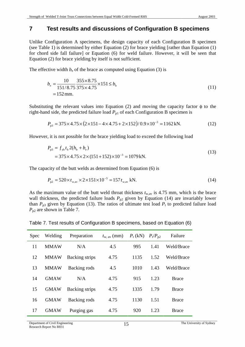
It is evident from Table 7 that Equation (6), which assumes that only the butt welds resist thebrace axial load, is conservative for Configuration B specimens. It appears that, for aConfiguration B specimen, the fillet welds across the chord face are also effective in resistingthe brace axial load due to the much thicker chord section relative to the brace. This indicationis supported by the fact that fracture initiation was observed along the fillet weld of Specimen15, as shown in Fig. 11.
Fig. 11 Fracture initiation along the fillet weld of Specimen 15
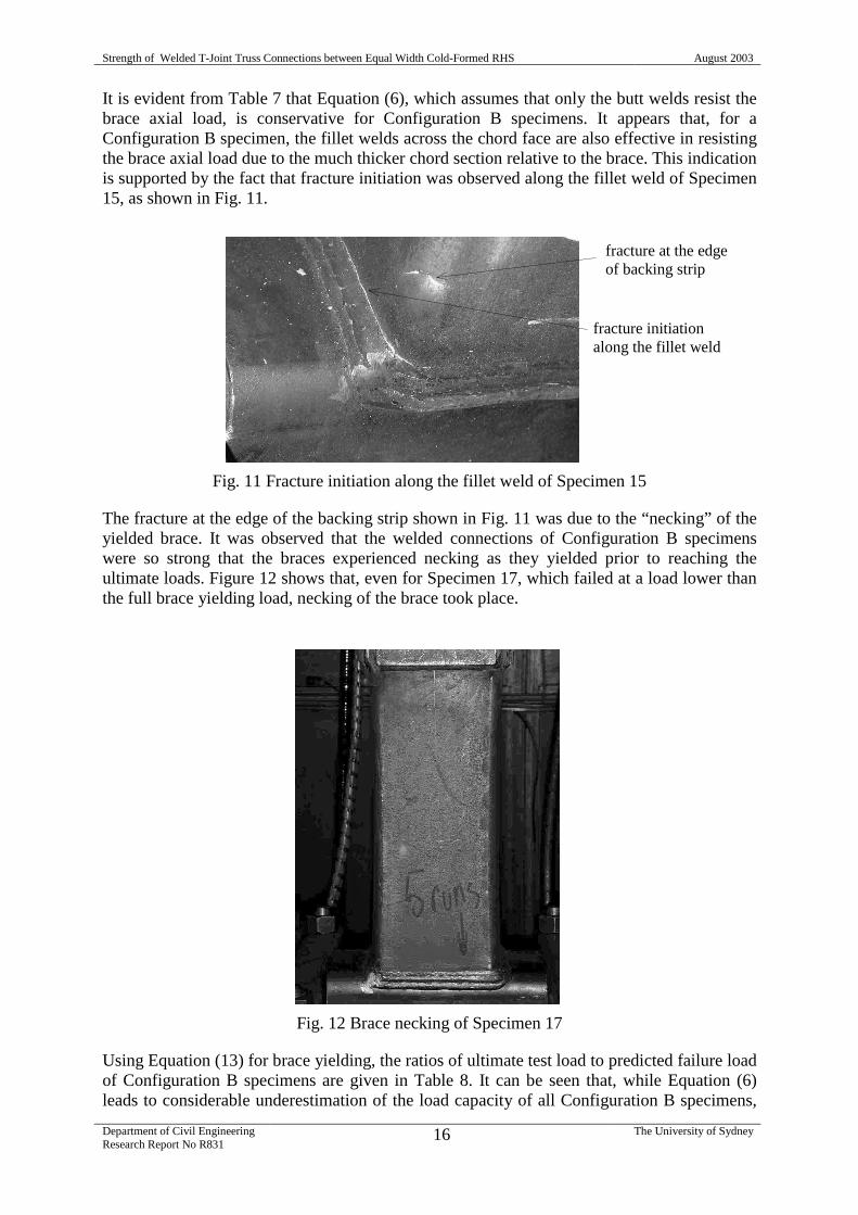
The fracture at the edge of the backing strip shown in Fig. 11 was due to the “necking” of theyielded brace. It was observed that the welded connections of Configuration B specimenswere so strong that the braces experienced necking as they yielded prior to reaching theultimate loads. Figure 12 shows that, even for Specimen 17, which failed at a load lower thanthe full brace yielding load, necking of the brace took place.
Fig. 12 Brace necking of Specimen 17
Using Equation (13) for brace yielding, the ratios of ultimate test load to predicted failure loadof Configuration B specimens are given in Table 8. It can be seen that, while Equation (6)leads to considerable underestimation of the load capacity of all Configuration B specimens,
fracture at the edgeof backing strip
fracture initiationalong the fillet weld
Strength of Welded T-Joint Truss Connections between Equal Width Cold-Formed RHS August 2003
Department of Civil EngineeringResearch Report No R831
17 The University of Sydney
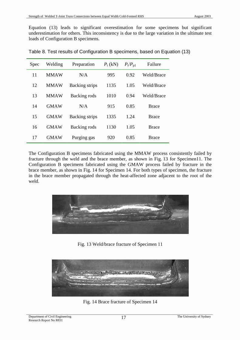
Equation (13) leads to significant overestimation for some specimens but significantunderestimation for others. This inconsistency is due to the large variation in the ultimate testloads of Configuration B specimens.
Table 8. Test results of Configuration B specimens, based on Equation (13)
Spec Welding Preparation Pt (kN) Pt/Pp1 Failure
11 MMAW N/A 995 0.92 Weld/Brace
12 MMAW Backing strips 1135 1.05 Weld/Brace
13 MMAW Backing rods 1010 0.94 Weld/Brace
14 GMAW N/A 915 0.85 Brace
15 GMAW Backing strips 1335 1.24 Brace
16 GMAW Backing rods 1130 1.05 Brace
17 GMAW Purging gas 920 0.85 Brace
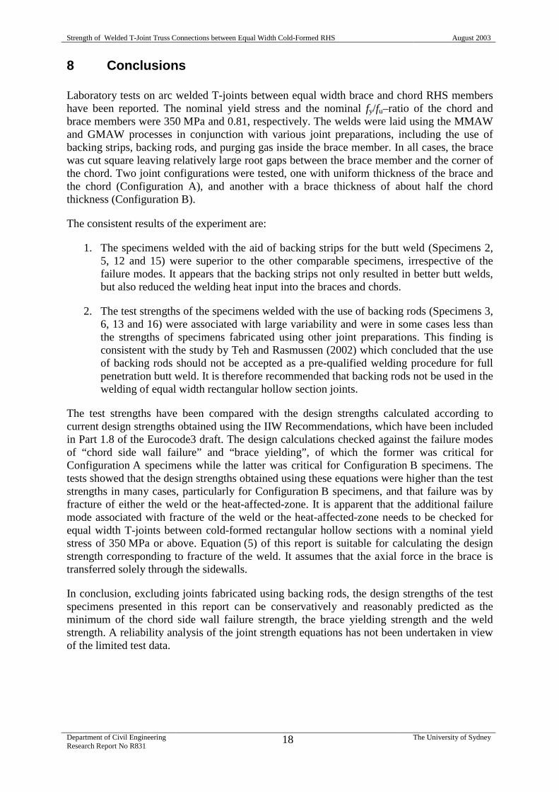
The Configuration B specimens fabricated using the MMAW process consistently failed byfracture through the weld and the brace member, as shown in Fig. 13 for Specimen11. TheConfiguration B specimens fabricated using the GMAW process failed by fracture in thebrace member, as shown in Fig. 14 for Specimen 14. For both types of specimen, the fracturein the brace member propagated through the heat-affected zone adjacent to the root of theweld.
Fig. 13 Weld/brace fracture of Specimen 11
Fig. 14 Brace fracture of Specimen 14
Strength of Welded T-Joint Truss Connections between Equal Width Cold-Formed RHS August 2003
Department of Civil EngineeringResearch Report No R831
18 The University of Sydney
8 Conclusions
Laboratory tests on arc welded T-joints between equal width brace and chord RHS membershave been reported. The nominal yield stress and the nominal fy/fu–ratio of the chord andbrace members were 350 MPa and 0.81, respectively. The welds were laid using the MMAWand GMAW processes in conjunction with various joint preparations, including the use ofbacking strips, backing rods, and purging gas inside the brace member. In all cases, the bracewas cut square leaving relatively large root gaps between the brace member and the corner ofthe chord. Two joint configurations were tested, one with uniform thickness of the brace andthe chord (Configuration A), and another with a brace thickness of about half the chordthickness (Configuration B).
The consistent results of the experiment are:
1. The specimens welded with the aid of backing strips for the butt weld (Specimens 2,5, 12 and 15) were superior to the other comparable specimens, irrespective of thefailure modes. It appears that the backing strips not only resulted in better butt welds,but also reduced the welding heat input into the braces and chords.
2. The test strengths of the specimens welded with the use of backing rods (Specimens 3,6, 13 and 16) were associated with large variability and were in some cases less thanthe strengths of specimens fabricated using other joint preparations. This finding isconsistent with the study by Teh and Rasmussen (2002) which concluded that the useof backing rods should not be accepted as a pre-qualified welding procedure for fullpenetration butt weld. It is therefore recommended that backing rods not be used in thewelding of equal width rectangular hollow section joints.
The test strengths have been compared with the design strengths calculated according tocurrent design strengths obtained using the IIW Recommendations, which have been includedin Part 1.8 of the Eurocode3 draft. The design calculations checked against the failure modesof “chord side wall failure” and “brace yielding”, of which the former was critical forConfiguration A specimens while the latter was critical for Configuration B specimens. Thetests showed that the design strengths obtained using these equations were higher than the teststrengths in many cases, particularly for Configuration B specimens, and that failure was byfracture of either the weld or the heat-affected-zone. It is apparent that the additional failuremode associated with fracture of the weld or the heat-affected-zone needs to be checked forequal width T-joints between cold-formed rectangular hollow sections with a nominal yieldstress of 350 MPa or above. Equation (5) of this report is suitable for calculating the designstrength corresponding to fracture of the weld. It assumes that the axial force in the brace istransferred solely through the sidewalls.
In conclusion, excluding joints fabricated using backing rods, the design strengths of the testspecimens presented in this report can be conservatively and reasonably predicted as theminimum of the chord side wall failure strength, the brace yielding strength and the weldstrength. A reliability analysis of the joint strength equations has not been undertaken in viewof the limited test data.
Strength of Welded T-Joint Truss Connections between Equal Width Cold-Formed RHS August 2003
Department of Civil EngineeringResearch Report No R831
19 The University of Sydney
Acknowledgments
The work reported herein was undertaken as part of a Research Project of the CooperativeResearch Centre for Welded Structures (CRC-WS). The CRC-WS was established and issupported under the Australian Government's Cooperative Research Centres Program. Thereport presents some of the results of the CRC project 2000-91 entitled “Welding ofRectangular Hollow Section Members of Equal Width”. The financial support provided by theCRC Welded Structures is greatly acknowledged as is the financial and in-kind supportprovided by OneSteel Market Mills . All the welded connections were fabricated by GrantHolgate in the Civil Engineering workshop at the University of Sydney. The WeldPrintmonitoring equipment was provided by Steve Simpson of the School of Electrical andInformation Engineering at the University of Sydney. The tests were conducted in the J. W.Roderick Laboratory for Structures and Materials at the University of Sydney. The writersalso thank Kim Pham for the prompt production of some illustrations used in the paper.
9 References
AWS (2000) Structural Welding Code – Steel, D1.1-98, 16th ed., American Welding Societyand American National Standards Institute, Miami, Florida, USA.
CEN (1993) Eurocode 3: Design of Steel Structures, Part 1.1 – General Rules and Rules forBuildings. European Committee for Standardisation, Brussels, Belgium.
CEN (2002) Eurocode 3: Design of Steel Structures, Part 1.8 – Design of Joints. EuropeanCommittee for Standardisation, Brussels, Belgium.
Davies, G., Wardenier, J., and Stolle, P. (1981) “The effective width of branch crosswalls forRR cross joints in tension,” Stevin Report No. 6-81-7, Delft University of Technology,The Netherlands.
Eastwood, W, and Wood, A. A. (1970a) “Welded joints in tubular structures involvingrectangular hollow sections,” Proc., Joints in Structures, Sheffield, England.
Eastwood, W, and Wood, A. A. (1970b) “Recent research on joints in tubular structures,”Proc., Canadian Structural Engineering Conference, Toronto, Canada.
Frater, G., and Packer, J. A. (1992a) “Weldment design for RHS truss connections. I:Applications,” J. Struct. Engrg., 118 (10), 2784-2803.
Frater, G., and Packer, J. A. (1992b) “Weldment design for RHS truss connections. I:Experimentation,” J. Struct. Engrg., 118 (10), 2804-2820.
IIW (1989) Design Recommendations for Hollow Section Joints – Predominantly StaticallyLoaded, 2nd ed., International Institute of Welding.
Korol, R. M., and Mirza, F. A. (1982) “Finite element analysis of RHS T-joints,” J. Struct.Div., ASCE, 108 (ST9), 2081-2098.
Kurobane, Y. (2002), “Connections in tubular structures,” Prog. Struct. Engrg. Mat., 4 (1), 35-45.
Packer, J. A., and Cassidy, C. E. (1995) “Effective weld lengths for HSS T, Y and Xconnections,” J. Struct. Engrg., 121 (10), 1402-1408.
Packer, J. A., and Henderson, J. E. (1997) Hollow Structural Section Connections andTrusses: A Design Guide, Canadian Institute of Steel Construction, Willowdale, Ontario.
Packer, J. A., Wardenier, J., Kurobane, Y., Dutta, D., and Yeomans, N. (1992) Design Guidefor Rectangular Hollow Section (RHS) Joints under Predominantly Static Loading,Verlag TUV Rheinland, Koln.
Ravindra, M.K., and Galambos, T.V. (1978), “Load and resistance factor design for steel”, J.Struct. Div., ASCE, 104 (ST9), 1337-1353.
Strength of Welded T-Joint Truss Connections between Equal Width Cold-Formed RHS August 2003
Department of Civil EngineeringResearch Report No R831
20 The University of Sydney
SA (1991a) Structural Steel Hollow Sections, AS 1163-1991, Standards Australia, Sydney.SA (1991b) Methods for Tensile Testing of Metals, AS 1391-1991, Standards Australia,
Sydney.SA (2003) Methods for destructive testing of welds in metal. Method 2.2: All-weld-metal
tensile test, AS 2205.2.2-2003, Standards Australia, Sydney.SA/SNZ (1995) Covered Electrodes for Welding – Low Carbon Steel Electrodes for MMAW
of Carbon Steels and Carbon-Manganese Steels, AS/NZS 1553.1:1995, StandardsAustralia/Standards New Zealand, Sydney.
SA/SNZ (1996). Welding – Electrodes - Gas Metal Arc - Ferritic Steel Electrodes, AS/NZS2717.1:1996, Standards Australia/Standards New Zealand, Sydney.
SA/SNZ (2000) Structural Steel Welding – Part 1: Welding of Steel Structures, AS/NZS1554.1:2000, Standards Australia/Standards New Zealand, Sydney.
Syam, A., and Chapman, B. (1996) Design of Structural Steel Hollow Section Connections,Vol. 1: Design Models, Australian Institute of Steel Construction, North Sydney,Australia.
Teh, L. H., and Rasmussen, K. J. R. (2002) “Strength of butt welded connections betweenequal width rectangular hollow sections,” Research Report No. R817, Department ofCivil Engineering, University of Sydney, Australia.
Wardenier, J., and de Koning, C. H. M. (1974) “Static tensile tests on T-joints in structuralhollow sections,” Stevin Report No. 6-74-7, Delft University of Technology, TheNetherlands.
Wilkinson, T. (1999) The Plastic Behaviour of Cold-Formed Rectangular Hollow Sections,PhD thesis, Department of Civil Engineering, University of Sydney, Australia.
Zhao, X. L. (2000) “Deformation limit and ultimate strength of welded T-joints in cold-formed RHS sections,” J. Constr. Steel Res., 53 (2), 149-165.

Strength of Welded T-Joint Truss Connections between Equal Width Cold-Formed RHS August 2003
Department of Civil EngineeringResearch Report No R831
21 The University of Sydney
Appendix I. Measuring average thickness of butt welds
Following the destructive tests of the Configuration A specimens which were fabricated usingthe MMAW process (see Section 6), it became apparent that full penetration was not achievedfor most of the butt welds of these specimens. For the purpose of determining the predictedfailure load of such a specimen based on the weld strength, as defined in Equation (6), theaverage thickness of its butt welds av,wt was measured from the macros of the intact butt weld
(the specimens invariably fractured only on one side of the T-joint).
Three fillets were cut off from the intact side of each specimen as illustrated in Fig. I.1, givingsix macros as each fillet has two sides. The weld thickness of each macro was taken as thethickness of its minimum cross section, rounded to the nearest 0.5 mm as shown in Table I.1for MMAW specimens, except for full butt welds in which case the wall thickness of thebrace member is assumed. The average thickness av,wt of a T-joint specimen was then
computed from the thickness of these six macros, also rounded to the nearest 0.5 mm.
Fig. I.1 Three fillets cut off from the intact side
Table I.1 Weld thicknesses of MMAW specimens
1 4.5 4.5 4 4 3.5 4
2
3 5.5 5.5 5.5 5.5 5.5 5.5
4 5.5 5.5 5 5 4 5.5
5 5 5 5.5 5 5.5 5.5
6 5 5.5 5.5 5.5 4.5 4.5
11 4.5 4.5 4.5 4.5 4.5 4.5
12
13 4.5 4.5 4.5 4.5 4.5 4.5
(full butt welds)
Butt / Groove weldChord
Brace
Adjacent face
Opposite face (seam weld face)
Cut formacros
(full butt welds)
Strength of Welded T-Joint Truss Connections between Equal Width Cold-Formed RHS August 2003
Department of Civil EngineeringResearch Report No R831
22 The University of Sydney
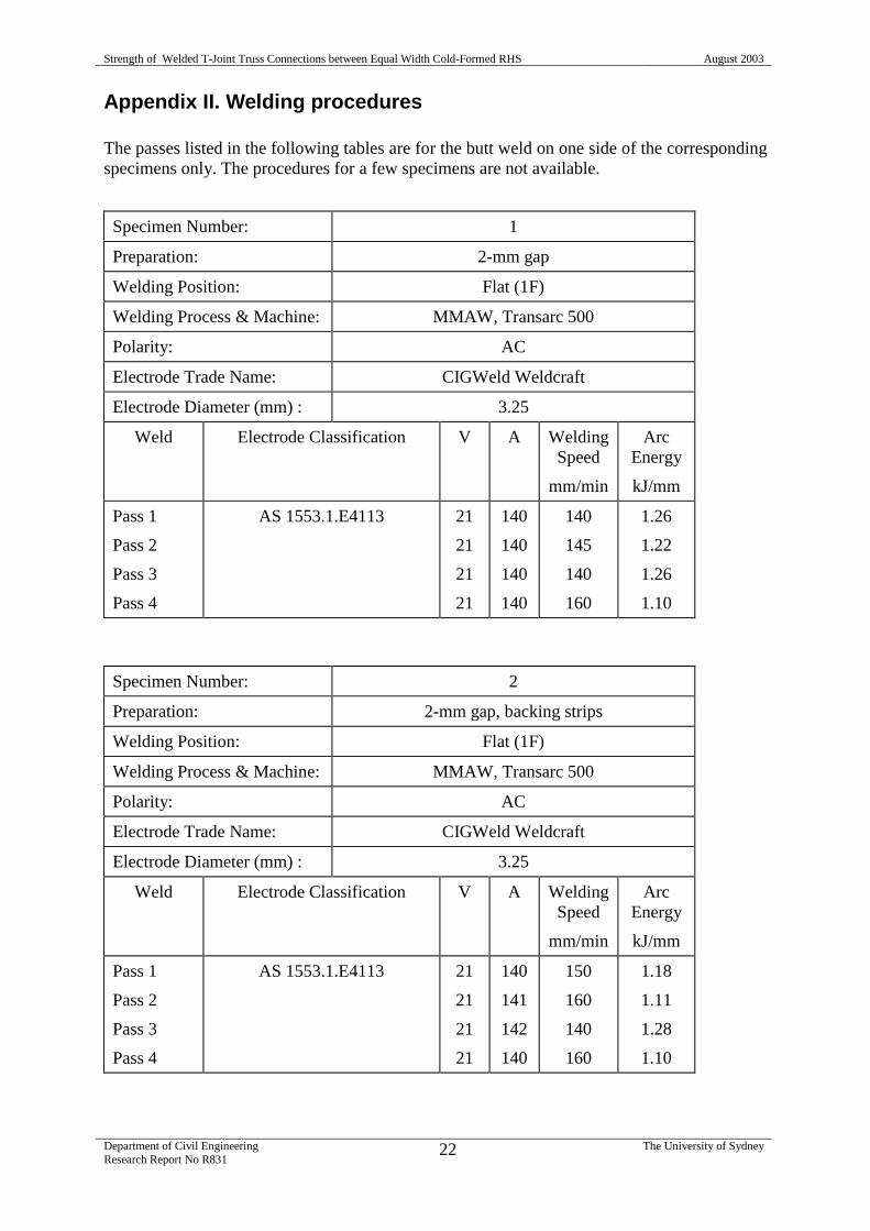
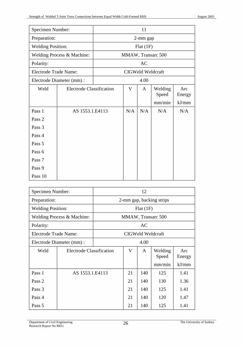
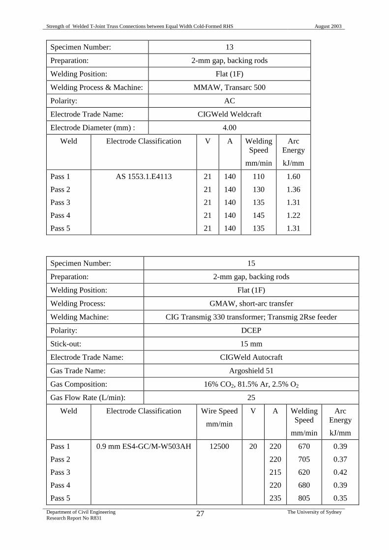
Appendix II. Welding procedures
The passes listed in the following tables are for the butt weld on one side of the correspondingspecimens only. The procedures for a few specimens are not available.
Specimen Number: 1
Preparation: 2-mm gap
Welding Position: Flat (1F)
Welding Process & Machine: MMAW, Transarc 500
Polarity: AC
Electrode Trade Name: CIGWeld Weldcraft
Electrode Diameter (mm) : 3.25
Weld Electrode Classification V A WeldingSpeed
mm/min
ArcEnergy
kJ/mm
Pass 1
Pass 2
Pass 3
Pass 4
AS 1553.1.E4113 21
21
21
21
140
140
140
140
140
145
140
160
1.26
1.22
1.26
1.10
Specimen Number: 2
Preparation: 2-mm gap, backing strips
Welding Position: Flat (1F)
Welding Process & Machine: MMAW, Transarc 500
Polarity: AC
Electrode Trade Name: CIGWeld Weldcraft
Electrode Diameter (mm) : 3.25
Weld Electrode Classification V A WeldingSpeed
mm/min
ArcEnergy
kJ/mm
Pass 1
Pass 2
Pass 3
Pass 4
AS 1553.1.E4113 21
21
21
21
140
141
142
140
150
160
140
160
1.18
1.11
1.28
1.10
Strength of Welded T-Joint Truss Connections between Equal Width Cold-Formed RHS August 2003
Department of Civil EngineeringResearch Report No R831
23 The University of Sydney
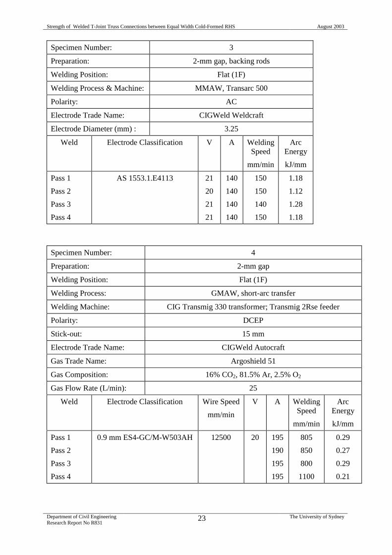
Specimen Number: 3
Preparation: 2-mm gap, backing rods
Welding Position: Flat (1F)
Welding Process & Machine: MMAW, Transarc 500
Polarity: AC
Electrode Trade Name: CIGWeld Weldcraft
Electrode Diameter (mm) : 3.25
Weld Electrode Classification V A WeldingSpeed
mm/min
ArcEnergy
kJ/mm
Pass 1
Pass 2
Pass 3
Pass 4
AS 1553.1.E4113 21
20
21
21
140
140
140
140
150
150
140
150
1.18
1.12
1.28
1.18
Specimen Number: 4
Preparation: 2-mm gap
Welding Position: Flat (1F)
Welding Process: GMAW, short-arc transfer
Welding Machine: CIG Transmig 330 transformer; Transmig 2Rse feeder
Polarity: DCEP
Stick-out: 15 mm
Electrode Trade Name: CIGWeld Autocraft
Gas Trade Name: Argoshield 51
Gas Composition: 16% CO2, 81.5% Ar, 2.5% O2
Gas Flow Rate (L/min): 25
Weld Electrode Classification Wire Speed
mm/min
V A WeldingSpeed
mm/min
ArcEnergy
kJ/mm
Pass 1
Pass 2
Pass 3
Pass 4
0.9 mm ES4-GC/M-W503AH 12500 20 195
190
195
195
805
850
800
1100
0.29
0.27
0.29
0.21
Strength of Welded T-Joint Truss Connections between Equal Width Cold-Formed RHS August 2003
Department of Civil EngineeringResearch Report No R831
24 The University of Sydney
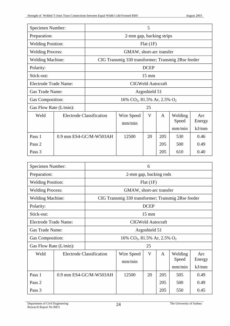
Specimen Number: 5
Preparation: 2-mm gap, backing strips
Welding Position: Flat (1F)
Welding Process: GMAW, short-arc transfer
Welding Machine: CIG Transmig 330 transformer; Transmig 2Rse feeder
Polarity: DCEP
Stick-out: 15 mm
Electrode Trade Name: CIGWeld Autocraft
Gas Trade Name: Argoshield 51
Gas Composition: 16% CO2, 81.5% Ar, 2.5% O2
Gas Flow Rate (L/min): 25
Weld Electrode Classification Wire Speed
mm/min
V A WeldingSpeed
mm/min
ArcEnergy
kJ/mm
Pass 1
Pass 2
Pass 3
0.9 mm ES4-GC/M-W503AH 12500 20 205
205
205
530
500
610
0.46
0.49
0.40
Specimen Number: 6
Preparation: 2-mm gap, backing rods
Welding Position: Flat (1F)
Welding Process: GMAW, short-arc transfer
Welding Machine: CIG Transmig 330 transformer; Transmig 2Rse feeder
Polarity: DCEP
Stick-out: 15 mm
Electrode Trade Name: CIGWeld Autocraft
Gas Trade Name: Argoshield 51
Gas Composition: 16% CO2, 81.5% Ar, 2.5% O2
Gas Flow Rate (L/min): 25
Weld Electrode Classification Wire Speed
mm/min
V A WeldingSpeed
mm/min
ArcEnergy
kJ/mm
Pass 1
Pass 2
Pass 3
0.9 mm ES4-GC/M-W503AH 12500 20 205
205
205
505
500
550
0.49
0.49
0.45
Strength of Welded T-Joint Truss Connections between Equal Width Cold-Formed RHS August 2003
Department of Civil EngineeringResearch Report No R831
25 The University of Sydney
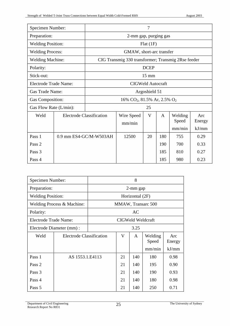
Specimen Number: 7
Preparation: 2-mm gap, purging gas
Welding Position: Flat (1F)
Welding Process: GMAW, short-arc transfer
Welding Machine: CIG Transmig 330 transformer; Transmig 2Rse feeder
Polarity: DCEP
Stick-out: 15 mm
Electrode Trade Name: CIGWeld Autocraft
Gas Trade Name: Argoshield 51
Gas Composition: 16% CO2, 81.5% Ar, 2.5% O2
Gas Flow Rate (L/min): 25
Weld Electrode Classification Wire Speed
mm/min
V A WeldingSpeed
mm/min
ArcEnergy
kJ/mm
Pass 1
Pass 2
Pass 3
Pass 4
0.9 mm ES4-GC/M-W503AH 12500 20 180
190
185
185
755
700
810
980
0.29
0.33
0.27
0.23
Specimen Number: 8
Preparation: 2-mm gap
Welding Position: Horizontal (2F)
Welding Process & Machine: MMAW, Transarc 500
Polarity: AC
Electrode Trade Name: CIGWeld Weldcraft
Electrode Diameter (mm) : 3.25
Weld Electrode Classification V A WeldingSpeed
mm/min
ArcEnergy
kJ/mm
Pass 1
Pass 2
Pass 3
Pass 4
Pass 5
AS 1553.1.E4113 21
21
21
21
21
140
140
140
140
140
180
195
190
180
250
0.98
0.90
0.93
0.98
0.71
Strength of Welded T-Joint Truss Connections between Equal Width Cold-Formed RHS August 2003
Department of Civil EngineeringResearch Report No R831
26 The University of Sydney
Specimen Number: 11
Preparation: 2-mm gap
Welding Position: Flat (1F)
Welding Process & Machine: MMAW, Transarc 500
Polarity: AC
Electrode Trade Name: CIGWeld Weldcraft
Electrode Diameter (mm) : 4.00
Weld Electrode Classification V A WeldingSpeed
mm/min
ArcEnergy
kJ/mm
Pass 1
Pass 2
Pass 3
Pass 4
Pass 5
Pass 6
Pass 7
Pass 9
Pass 10
AS 1553.1.E4113 N/A N/A N/A N/A
Specimen Number: 12
Preparation: 2-mm gap, backing strips
Welding Position: Flat (1F)
Welding Process & Machine: MMAW, Transarc 500
Polarity: AC
Electrode Trade Name: CIGWeld Weldcraft
Electrode Diameter (mm) : 4.00
Weld Electrode Classification V A WeldingSpeed
mm/min
ArcEnergy
kJ/mm
Pass 1
Pass 2
Pass 3
Pass 4
Pass 5
AS 1553.1.E4113 21
21
21
21
21
140
140
140
140
140
125
130
125
120
125
1.41
1.36
1.41
1.47
1.41
Strength of Welded T-Joint Truss Connections between Equal Width Cold-Formed RHS August 2003
Department of Civil EngineeringResearch Report No R831
27 The University of Sydney
Specimen Number: 13
Preparation: 2-mm gap, backing rods
Welding Position: Flat (1F)
Welding Process & Machine: MMAW, Transarc 500
Polarity: AC
Electrode Trade Name: CIGWeld Weldcraft
Electrode Diameter (mm) : 4.00
Weld Electrode Classification V A WeldingSpeed
mm/min
ArcEnergy
kJ/mm
Pass 1
Pass 2
Pass 3
Pass 4
Pass 5
AS 1553.1.E4113 21
21
21
21
21
140
140
140
140
140
110
130
135
145
135
1.60
1.36
1.31
1.22
1.31
Specimen Number: 15
Preparation: 2-mm gap, backing rods
Welding Position: Flat (1F)
Welding Process: GMAW, short-arc transfer
Welding Machine: CIG Transmig 330 transformer; Transmig 2Rse feeder
Polarity: DCEP
Stick-out: 15 mm
Electrode Trade Name: CIGWeld Autocraft
Gas Trade Name: Argoshield 51
Gas Composition: 16% CO2, 81.5% Ar, 2.5% O2
Gas Flow Rate (L/min): 25
Weld Electrode Classification Wire Speed
mm/min
V A WeldingSpeed
mm/min
ArcEnergy
kJ/mm
Pass 1
Pass 2
Pass 3
Pass 4
Pass 5
0.9 mm ES4-GC/M-W503AH 12500 20 220
220
215
220
235
670
705
620
680
805
0.39
0.37
0.42
0.39
0.35
Strength of Welded T-Joint Truss Connections between Equal Width Cold-Formed RHS August 2003
Department of Civil EngineeringResearch Report No R831
28 The University of Sydney