DEPAC Dyno Systems
29
Transcript of DEPAC Dyno Systems
1
DEPAC Dyno Systems 201 Mill St. Rome NY 13440 (315) 339 –[email protected] www.depac.com
MAIN INTRODUCTION: Dyno Control InnovationAuto-Dynamic Load (ADL) Control System for water brake dynos:The ADL Control System is a significant advance in the control and operation of thecommon water brake dyno. It is a Smart Load Control that works far better than thetraditional Speed Control Dynos in wide use. It is also very easy to set up and operate andmost anyone can easily run the dyno. It achieves excellent control of engine load and speedby Improving the Stability of the Dyno/Engine connection. Unlike Speed Controls, the ADLsystem does not require adjustments and provides the engine with a very smooth andnatural load, either steady state or sweeping. The ADL system controls dyno inlet waterflow to Most* dynos. This is the proper method to control the load from a water brake.Also, designed into the hardware is the ability for future upgrades of the ADL to provide fullprogrammed automated testing, track, Throttle control, and inertia dyno simulations.Dyno Applications:The ADL Control System is upgrades existing manual dynos like Stuska®, Go- Power,Froude, AVL, and many others. We will provide upgrade parts kits for each specific dyno.DTS Power-Mark and SuperFlow™ dynos can be upgraded as well. But the completeupgrade includes an ADL Control AND a precision DEPAC instrumentation package.Special INSTALLATION Requirements for the ADL Control System:Please MAKE the time to read and understand the included ADL instructions and MAKE thetime to do all that's required for the system installation to work at 100% performance.The ADL system works differently than any other previous dyno control system andrequires special considerations for the water plumbing if it is to work to its full potential.It is very important to follow the installation instructions and diagrams. We provide thesystem as a kit of most all needed parts and clear, specific instructions so that it is installedproperly. The ADL system can be made to work well with most existing plumbing (that isusually strung-out). Any new installation should try to place the dyno, pump, and watersupply in close proximity (Just because there is no need to have lines strung all over theshop). Some existing dynos use municipal water through a long underground line. You cancontinue to use this city water supply as long as it has enough pressure for the engines, youneed to test, and you will need extra Accumulators.Most installations requires a diaphragm accumulator near the Inlet Control Valve, asshown in the diagrams, pre-charged with air to 70% of the working water pressure. Someinstallations may require more than one Accumulator to compensate for the water flowinertia of very long water lines. A special inlet hose and nipple is supplied to connect theaccumulator to the inlet valve (see diagrams). The outlet water is required to drain freely intoa lower sump tank or open drain.Dual rotor dynos have very special requirements in that the water flow through each half beequal for best dyno load performance. We try to provide the parts and special manifolds toprovide a 50-50 split of the inlet and outlet water flow.* SuperFlow™ dynos use a specially designed Outlet Valve that’s fast and precise.
2
DEPAC Dyno Systems 201 Mill St. Rome NY 13440 vv(315) 339 [email protected] www.depac.com
To Run an ADL Controlled dyno test all you need to do:1. Start the pre-warmed engine.2. Pickup the throttle (the Load is automatically applied)3. Hold the Test Switch down (to Sweep or Hold steady state).4. Release the test switch when test is finished.5. Pull throttle back to idle.New Technology: The ADL Control system is Not a Speed control. This system is Superior toany dyno speed controls we have ever seen, at any cost. The Key feature of the ADL system isa Smart Load that's Smooth and Natural and very Stable. Picture your engine as powering avehicle climbing a steep hill, or grade. The ADL System affects the engine speed by changingthe Grade, or slope, of this simulated hill. It is a very natural simulation and enhances your'feel' for when the engine is 'not right'. If the engine is running the same then it will reach thesame RPM when climbing the same Grade setting or LOAD. Sweeps are also very natural andstart by setting a LOAD or Grade to hold a start RPM at a fixed throttle setting. For a Sweep,this Grade is slowly Reduced to sweep Up (or Increased to sweep Down). So then Imaginethat you are in this vehicle on a sustained grade and then the hill starts to slowly flatten out.The engine picks up RPM in a smooth and natural way (as long as the engine is runningsmooth). The RATE control knob sets how Quickly this Grade changes when sweeping Up orDown, and can range from seconds to minutes. If you start at a Low RPM (hi Load) and startan Up-Sweep, the engine smoothly accelerates Naturally as it comes up on the cam, just asyou would experience in the real world. Each sweep, or run 'up the hill', is very repeatable andpredictable. Any sweep rate change is primarily due to the engine's ability to accelerate.Tests can be done at any throttle setting. Set a cracked throttle to simulate cruising conditions.At startup, and at low idle speeds, there is no Grade and just a slight engine load. As youincrease the throttle, the Grade increases progressively until you reach a balanced RPM at aset throttle position (full or partial). If the engine is repeatable it will reach the Same RPM eachtime for the same throttle position. Any time you pull back the throttle to an idle the Gradeautomatically flattens out to a slight road load.Another Key Feature is that you have an enhanced sense of how well the engine is running,much more than you had with your hand valve, and certainly better than with any speedcontrol. If you make a change to the engine that increases its performance it will reach a higherRPM at the same throttle setting. If the engine has a problem it will not reach the expectedRPM and you can see immediately that there is something wrong. Note that Speed Controls,besides being erratic and un-natural, will run an engine to destruction, while trying to hold a setRPM. You may not detect something is wrong until too late (and expensive to fix).The ADL Control Includes is an available RPM HOLD Mode. It is a simple speed control that isintended for engine/injection mapping and will hold any set RPM from 1,000 to 12,000 RPM inprecise 100 RPM increments.An added feature aids in warming up the engine. In this Warmup Mode the load is cycled tovary the Load and RPM in a continuous loop. You should never let the engine run at a steadyspeed for warm-up or break-in because of possible destructive torsional resonances.
A
B
C
D
F
G
E
HX Y Z
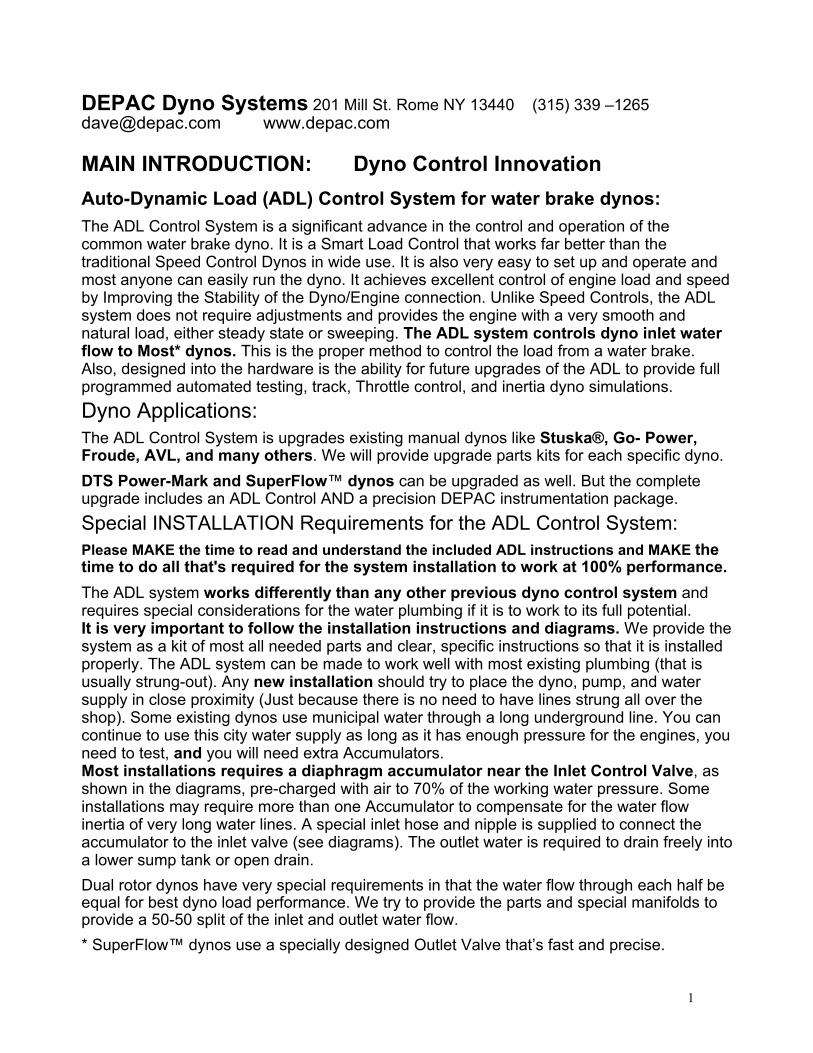
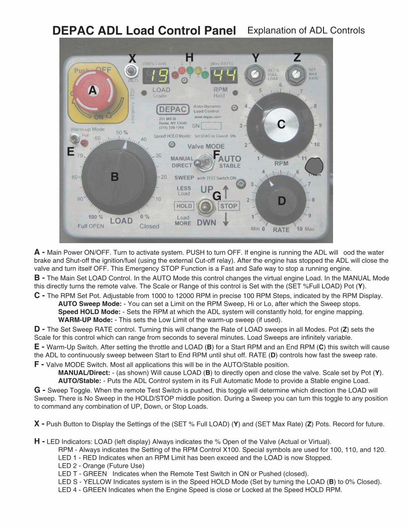
DEPAC ADL Load Control Panel Explanation of ADL Controls
A - Main Power ON/OFF. Turn to activate system. PUSH to turn OFF. If engine is running the ADL will flood the water brake and Shut-off the ignition/fuel (using the external Cut-off relay). After the engine has stopped the ADL will close the valve and turn itself OFF. This Emergency STOP Function is a Fast and Safe way to stop a running engine.B - The Main Set LOAD Control. In the AUTO Mode this control changes the virtual engine Load. In the MANUAL Mode this directly turns the remote valve. The Scale or Range of this control is Set with the (SET %Full LOAD) Pot (Y).C - The RPM Set Pot. Adjustable from 1000 to 12000 RPM in precise 100 RPM Steps, indicated by the RPM Display. AUTO Sweep Mode: - You can set a Limit on the RPM Sweep, Hi or Lo, after which the Sweep stops. Speed HOLD Mode: - Sets the RPM at which the ADL system will constantly hold, for engine mapping. WARM-UP Mode: - This sets the Low Limit of the warm-up sweep (if used).D - The Set Sweep RATE control. Turning this will change the Rate of LOAD sweeps in all Modes. Pot (Z) sets the Scale for this control which can range from seconds to several minutes. Load Sweeps are infinitely variable.E - Warm-Up Switch. After setting the throttle and LOAD (B) for a Start RPM and an End RPM (C) this switch will cause the ADL to continuously sweep between Start to End RPM until shut off. RATE (D) controls how fast the sweep rate.F - Valve MODE Switch. Most all applications this will be in the AUTO/Stable position. MANUAL/Direct: - (as shown) Will cause LOAD (B) to directly open and close the valve. Scale set by Pot (Y). AUTO/Stable: - Puts the ADL Control system in its Full Automatic Mode to provide a Stable engine Load.G - Sweep Toggle. When the remote Test Switch is pushed, this toggle will determine which direction the LOAD will Sweep. There is No Sweep in the HOLD/STOP middle position. During a Sweep you can turn this toggle to any position to command any combination of UP, Down, or Stop Loads.
X - Push Button to Display the Settings of the (SET % Full LOAD) (Y) and (SET Max Rate) (Z) Pots. Record for future.
H - LED Indicators: LOAD (left display) Always indicates the % Open of the Valve (Actual or Virtual). RPM - Always indicates the Setting of the RPM Control X100. Special symbols are used for 100, 110, and 120. LED 1 - RED Indicates when an RPM Limit has been exceed and the LOAD is now Stopped. LED 2 - Orange (Future Use) LED T - GREEN Indicates when the Remote Test Switch in ON or Pushed (closed). LED S - YELLOW Indicates system is in the Speed HOLD Mode (Set by turning the LOAD (B) to 0% Closed). LED 4 - GREEN Indicates when the Engine Speed is close or Locked at the Speed HOLD RPM.
4
DEPAC Dyno Systems 201 Mill St. Rome NY 13440 (315) 339 [email protected] www.depac.com
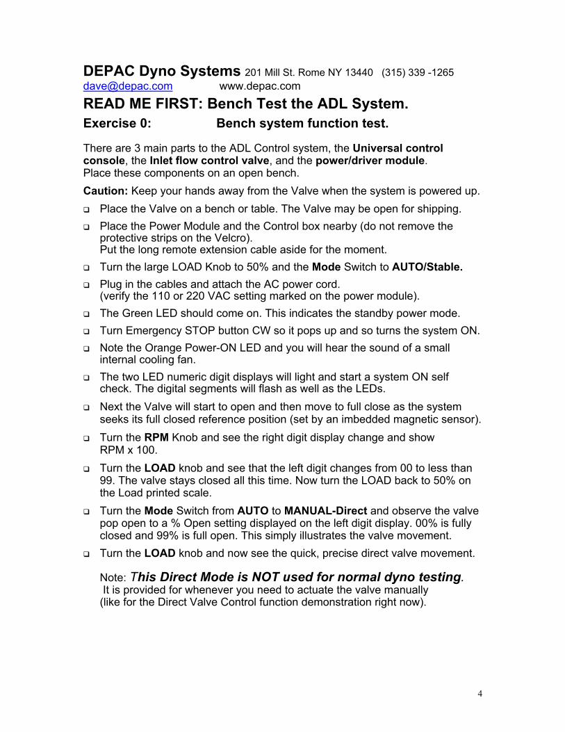
READ ME FIRST: Bench Test the ADL System.Exercise 0: Bench system function test.
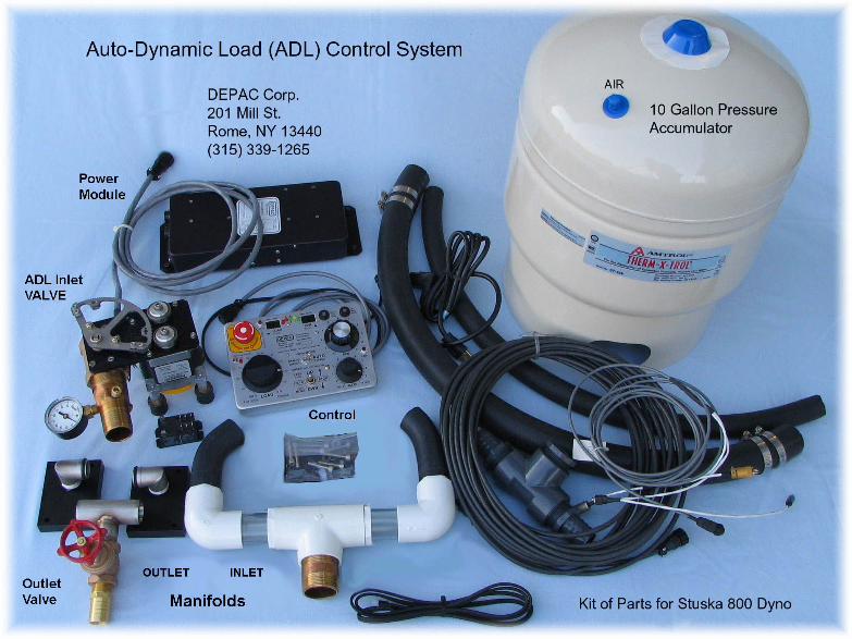
There are 3 main parts to the ADL Control system, the Universal controlconsole, the Inlet flow control valve, and the power/driver module.Place these components on an open bench.Caution: Keep your hands away from the Valve when the system is powered up.
Place the Valve on a bench or table. The Valve may be open for shipping. Place the Power Module and the Control box nearby (do not remove the
protective strips on the Velcro).Put the long remote extension cable aside for the moment.
Turn the large LOAD Knob to 50% and the Mode Switch to AUTO/Stable. Plug in the cables and attach the AC power cord.
(verify the 110 or 220 VAC setting marked on the power module). The Green LED should come on. This indicates the standby power mode. Turn Emergency STOP button CW so it pops up and so turns the system ON. Note the Orange Power-ON LED and you will hear the sound of a small
internal cooling fan. The two LED numeric digit displays will light and start a system ON self
check. The digital segments will flash as well as the LEDs. Next the Valve will start to open and then move to full close as the system
seeks its full closed reference position (set by an imbedded magnetic sensor). Turn the RPM Knob and see the right digit display change and show
RPM x 100. Turn the LOAD knob and see that the left digit changes from 00 to less than
99. The valve stays closed all this time. Now turn the LOAD back to 50% onthe Load printed scale.
Turn the Mode Switch from AUTO to MANUAL-Direct and observe the valvepop open to a % Open setting displayed on the left digit display. 00% is fullyclosed and 99% is full open. This simply illustrates the valve movement.
Turn the LOAD knob and now see the quick, precise direct valve movement.
Note: This Direct Mode is NOT used for normal dyno testing. It is provided for whenever you need to actuate the valve manually(like for the Direct Valve Control function demonstration right now).
5
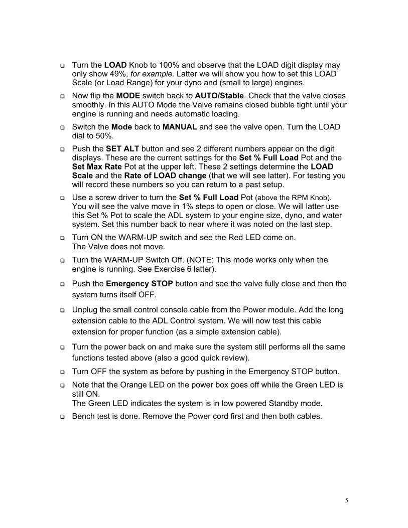
Turn the LOAD Knob to 100% and observe that the LOAD digit display mayonly show 49%, for example. Latter we will show you how to set this LOADScale (or Load Range) for your dyno and (small to large) engines.
Now flip the MODE switch back to AUTO/Stable. Check that the valve closessmoothly. In this AUTO Mode the Valve remains closed bubble tight until yourengine is running and needs automatic loading.
Switch the Mode back to MANUAL and see the valve open. Turn the LOADdial to 50%.
Push the SET ALT button and see 2 different numbers appear on the digitdisplays. These are the current settings for the Set % Full Load Pot and theSet Max Rate Pot at the upper left. These 2 settings determine the LOADScale and the Rate of LOAD change (that we will see latter). For testing youwill record these numbers so you can return to a past setup.
Use a screw driver to turn the Set % Full Load Pot (above the RPM Knob).You will see the valve move in 1% steps to open or close. We will latter usethis Set % Pot to scale the ADL system to your engine size, dyno, and watersystem. Set this number back to near where it was noted on the last step.
Turn ON the WARM-UP switch and see the Red LED come on.The Valve does not move.
Turn the WARM-UP Switch Off. (NOTE: This mode works only when theengine is running. See Exercise 6 latter).
Push the Emergency STOP button and see the valve fully close and then thesystem turns itself OFF.
Unplug the small control console cable from the Power module. Add the longextension cable to the ADL Control system. We will now test this cableextension for proper function (as a simple extension cable).
Turn the power back on and make sure the system still performs all the samefunctions tested above (also a good quick review).
Turn OFF the system as before by pushing in the Emergency STOP button. Note that the Orange LED on the power box goes off while the Green LED is
still ON.The Green LED indicates the system is in low powered Standby mode.
Bench test is done. Remove the Power cord first and then both cables.
6
ADL Control System Installation: Stuska® 800Before Any installation: See Exercise 0 to bench test system.Stuska® 800 Dual Rotor: Read section on Special needs for this dyno.Refer to the diagrams of a standard installation on a Stuska® 800 dyno. Please Follow the Diagrams and Instructions and the system will run 100%.A New Dyno Installation: For a new dyno installation locate the water supply, pump, anddyno as close together as practical to avoid long water lines. Use the 150 PSI rated EDPMrubber hose instead of PVC, or solid piping, and elbows. Also can use 125 PSI rated hose.An Existing Dyno Installation: The ADL Control system can use your existing pump andyour existing plumbing. The water inlet and outlet at the dyno needs to be as shown in thediagrams. Most all the parts are provided in the kit to make this installation right. Checkthat your existing plumbing is not restricting flow. Lines that are 1½" pipe size and morewill work. If the length of the overall plumbing is more than 50 feet then you will Need a 2nd
Accumulator to compensate for water column inertia (which slows, or lags, operation). - - - - - - - - - - - - - - - - - - - - - - - - - - - - - - - - - - - - - - - - - - - - - - - - - - - - - - - - - - - - - - - -Inlet valve assembly: Mount the ADL Control valve as shown in the diagrams using theparts supplied in the kit. The Inlet barbed fitting (with PSI Gauge) and the 2 foot flexiblehose section and Accumulator must be used close, as shown in the diagram (shorten to15” minimum). The vertical inlet hose supports, and balances, the valve assembly on top.Provide support for the inlet hose so that the valve and inlet manifold is centered on top ofthe dyno as shown. Normally the valve is closed and there will always be water in the lineabove the valve. Always bring the water hose over from the back of the dyno, not from thesides. We have a 10-32 barbed fitting on the valve inlet that you can connect to the smallStuska® hose for cooling the Stuska® water seals. Use the small hose parts provided.
Mount the Accumulator: Make a frame to Support the weight of the water filledaccumulator and the water filled hoses. Be careful not to cause a torque on the brakeassembly. The 2 foot hose must be used to form, or straighten, the flow into the valve.
Charging the Accumulator: Inflate the Accumulator with air, or inert gas, to 70% of theinlet valve's working water pressure. The Working pressure is the Water PSI with theengine fully loaded. Use the PSI gauge on the valve inlet for reference. We recommendthat you also have an operator panel gauge, using a remote line to this fitting. Check andSet Air Pressure with the pump Off and no water pressure.
Mount the Outlet Valve Assembly: Remove the current Stuska® Outlet flanges andscrap off all the silicone to have a clean flat surface for our new O-ring flange seal.Assemble the 2 outlet flanges together with the valve Tee. (Apply a little grease to the O-ring and inside surface). Observe the orientation of the plates for dyno rotation (just likethe original Stuska® flanges). For counter-rotating engines you Must rotate these flanges,just like before, but now its easier. Also apply a little grease to the O-Ring flange. Use thestainless caps screws and washers supplied. Refer to the diagram for position androtation. After running warm a few times Check to see if the Gate Valve Packing nut issnug (hard to turn) so that the valve keeps its position and is not loose to turn.
7
Use a 1" rubber hose to direct the outlet water into an open sump or drain. This hoseshould be as short as possible and no more than 24" long. The hose should be directedstraight down to minimize flow caused torque. Add a support bracket to end of the hose sothat it does not rotate on the O-rings. You can direct the hose to the back BUT not to theside, as this will pull on the dyno causing a false torque. Do not use the Dyno to pumpwater into another tank as this added restriction affects the outlet flow. Avoid recalculatingthe hot outlet water directly back to the supply tank if it will significantly raise thetemperature of the inlet water (which should always be as cool as possible). If you need tore-use the outlet water you ought to cool the water before returning to the supply tank.Mount the Power/Driver Module: The Valve actuator cable (8') plugs into the Power-Driver module. The Power Module needs to be located far from any radiant heat sources,like the exhaust and cooling system. It needs to be in the open where cool moving roomair will flow over it. Mount it on a wall or vibration free support. Do NOT mount on the Dynoframe because of the vibration and proximity of heat. Use 8-32 or the screws provided.Plug in the power cord securely to the Power Module (remains powered-up in Standby).120 or 240 AC and the unit can be powered ON all the time.Note: Wire this power to its own breaker circuit. If you have this on the same circuit usedfor pumps, fans, or other motors, the unit can be damaged from inductive voltage kickbackspikes when the circuit breaks on a running motor. Never wire anything to a circuit that’sconnected to a running motor. Huge arcs are created when switching off a running motor.
Mount the Operator Control Console: There are two recommended ways to mount theoperator panel. Use the Velcro strips or sink into a panel cutout. Use the Velcro strips forinitial location, which should be easily accessible while running the tests. When you haveselected a good location, for easy manual operation, you can carefully make a 5 ½" by 8"cutout so that the panel will drop in snuggly up to its top flange. The Box is slightly taperedand the aim is to have a snug fit but still be able to pull up and out for service and re-programming. Please do not drill holes or using silly-cone.
Optional use: Ignition Cut-Off Relay: The ADL Control panel has a pair of wires for anexternal relay that you can use as an ignition cutoff for either magneto (close circuit) orconventional ignitions (open circuit). It is connected to the panel's Emergency STOPbutton. Hitting this E-STOP Button, when the engine is running, also commands the LoadValve to flood the dyno. When the engine is stopped it closes the valve and shuts itself off.Flooding the dyno alone is not enough to stall an engine, but the combination of quickdyno flooding and ignition cutoff stops the engine the quickest, when you really need to.Connect the relay to 12 Volt battery power and the relay contacts as needed for yourignition (see wiring diagram). Avoid mounting on the vibrating dyno frame. The relay isEnergized when the ADL system is turned ON. This then enables the Ignition (and fuelpump). When using this Emergency Cut-Off relay the ADL System needs to be turned onBefore you can start the engine.
8
DEPAC Dyno Systems 201 Mill St. Rome NY 13440 (315) [email protected] www.depac.com
INLET Valve Assembly: InstallationThe Butterfly Valve can accept water flow from either direction.The Valve uses an O-Ring seal for a self-cleaning, bubble tight, shutoff.We have provided most all the parts for a proper installation. Refer to the diagrams.Special Inlet Barbed Hose fitting: There are several tapped holes on this adapter. It’svery important that any pipe fittings be FLUSH on the inside. That is why they are tappedshallow so please do not tap deeper. For Dual Rotor dynos the water flow Must be split50/50% for each half rotor else the dyno may run erratically. Any protrusions will alter thedynamic (turbulent) water flow and possibly alter the 50/50% flow split from the valve. Makesure any fittings are flush inside by grinding. Protrusions will distort the flow lines.The water flow path must be symmetrical so that it will not alter the 50/50% flow split. Theinlet hose fitting has a constriction that helps direct an even flow to the butterfly valve andthe 18-24" length of 1.5" EDPM hose supplied Must be Used. The Absolute Worst thingyou could do is to put a 90 degree elbow on the valve inlet.Inlet Water Pressure Gauge and Sensor: The valve depends on a stable and consistentwater supply pressure at the valve so it can control water flow into the dyno. We supply aWater PSI gauge for you to locally monitor this important pressure. We have provided 3possible locations for the Gauge so that you can see it better after you have tightened thepipe thread Hose fitting. Adding an additional remote pressure gauge is encouraged.We supply pipe plugs for those that are not used. Check to see if these are all Flush withthe inside surface of the hose fitting. (We tap threads shallow to help get a flush fitting).10-32 tapped holes are for you to use with the Stuska® water drip lines to the brake.
Stuska® 800, DTS, Froude Dynos: 50/50% Water Flow Split Manifold:For Stuska 800 we provide all the PVC plumbing parts so you can make the water flowsplitter shown in the diagrams. The valve outlet is 1 ½” NPT. The oldest Stuska® used a 1"brass pipe nipple with ¾” NPT. Its best to open this up and tap 1" NPT to use the 1¼” hosenipple provided. This will allow consistent use of 1 ¼" molded hoses for all Stuska®installations. 2nd best is to use spacer provided over the 1" fitting to fill the gap to the 1 ¼"molded hose. The water pressure in this manifold is very low and so you may not evenneed to use any hose clamps. (Certainly don’t over clamp).Stuska® 400 , Go-Power, and Single Rotor Dynos. The inlet Valve controls theflow to the single water inlet and should be mounted as shown in the diagrams close to thedyno. We do not want the hose, and the water flow, to pull on the dyno and cause torqueerrors. Check for this by running the ADL in the Manual/Direct Mode to create a Pulse ofwater flow and watch the torque readings jump. Just use a quick blip of water flow since thedyno can be filled quickly and pressure can build inside (with no engine running).
9
DEPAC Dyno Systems 201 Mill St. Rome NY 13440 (315) 339 [email protected] www.depac.com
Installing the Universal ADL Operator Control Panel:This Same Panel is used for all different dynos to provide a consistentuniversal operator interface. This provides a consistent, universal, interface sothat you can easily operate different ADL equipped dynos, once you havelearned to use on another dyno.
The control panel has Velcro strips attached to the bottom. Use this first to placethe box onto your control panel where you can easily get at the manual controls.Move the box around your console until you locate a sweet spot and then removethe protective strips and push down hard on the flat surface. Latter, if you like,you can carefully cut out a 5 ½" by 8" opening so that the panel can sink up to itstop cover flange for a near Flush mount. The sides of the box are slightly taperedand if you get the opening just right it will lock in snuggly but still can be lifted outeasily if needed, like to return to DEPAC for updated programming. (PLEASE, donot use any screws or silly-cone). Let gravity, and a snug fit, do the work.There are several cables that exit the box. All have connectors for easy removalof the box.The 1st cable goes out to the Power Module, mounted near the valve. Weinclude a 45 foot extension cable. Route this cable out of harm's way.A 2nd cable has connections for the Tach signal input and the Test Switch. If youhave a DEPAC system, we supply the ends so that you can Tap into the existingTach input and Remote test Switch plug. This cable will be bare wires if you donot have a DEPAC instrumentation system. (2 pair for Tach input & Test Switch).A 3rd cable (2 wire with connector) can be used with a remote ignition cut-outrelay. This works in conjunction with the Red Emergency STOP switch.Emergency Stop will flood the dyno and kill the ignition. This relay can also beused to cutoff any electric fuel pumps. When the engine has stopped turning, theADL system will close the valve and automatically power down.
10
DEPAC Dyno Systems 201 Mill St. Rome NY 13440 (315) 339 [email protected] www.depac.com
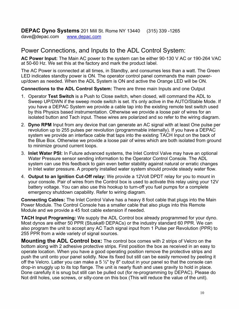
Power Connections, and Inputs to the ADL Control System:AC Power Input: The Main AC power to the system can be either 90-130 V AC or 190-264 VACat 50-60 Hz. We set this at the factory and mark the product label.The AC Power is connected at all times, in Standby, and consumes less than a watt. The GreenLED indicates standby power is ON. The operator control panel commands the main power-up/down as needed. When the ADL System is ON and active the Orange LED will be ON.Connections to the ADL Control System: There are three main Inputs and one Output1. Operator Test Switch is a Push to Close switch, when closed, will command the ADL to
Sweep UP/DWN if the sweep mode switch is set. It's only active in the AUTO/Stable Mode. Ifyou have a DEPAC System we provide a cable tap into the existing remote test switch usedby this Physics based instrumentation. Otherwise we provide a loose pair of wires for anisolated button and Tach input. These wires are polarized and so refer to the wiring diagram.
2. Dyno RPM Input from any device that can generate an AC signal with at least One pulse perrevolution up to 255 pulses per revolution (programmable internally). If you have a DEPACsystem we provide an interface cable that taps into the existing TACH Input on the back ofthe Blue Box. Otherwise we provide a loose pair of wires which are both isolated from groundto minimize ground current loops.
3. Inlet Water PSI: In Future advanced systems, the Inlet Control Valve may have an optionalWater Pressure sensor sending information to the Operator Control Console. The ADLsystem can use this feedback to gain even better stability against natural or erratic changesin Inlet water pressure. A properly installed water system should provide steady water flow.
4. Output to an Ignition Cut-Off relay: We provide a 12Volt DPDT relay for you to mount inyour console. Pair of wires from the Control box is used to activate this relay using your 12Vbattery voltage. You can also use this hookup to turn-off you fuel pumps for a completeemergency shutdown capability. Refer to wiring diagram.
Connecting Cables: The Inlet Control Valve has a heavy 8 foot cable that plugs into the MainPower Module. The Control Console has a smaller cable that also plugs into this RemoteModule and we provide a 45 foot cable extension if needed.TACH Input Programing: We supply the ADL Control box already programmed for your dyno.Most dynos are either 50 PPR (Stuska® DEPACs) or the industry standard 60 PPR. We canalso program the unit to accept any AC Tach signal input from 1 Pulse per Revolution (PPR) to255 PPR from a wide variety of signal sources.Mounting the ADL Control box: The control box comes with 2 strips of Velcro on thebottom along with 2 adhesive protective strips. First position the box as received in an easy tooperate location. When you have a good operating position remove the protective strips andpush the unit onto your panel solidly. Now its fixed but still can be easily removed by peeling itoff the Velcro. Latter you can make a 5 ½" by 8" cutout in your panel so that the console candrop-in snuggly up to its top flange. The unit is nearly flush and uses gravity to hold in place.Done carefully it is snug but still can be pulled out (for re-programming by DEPAC). Please doNot drill holes, use screws, or silly-cone on this box (This will reduce the value of the unit).
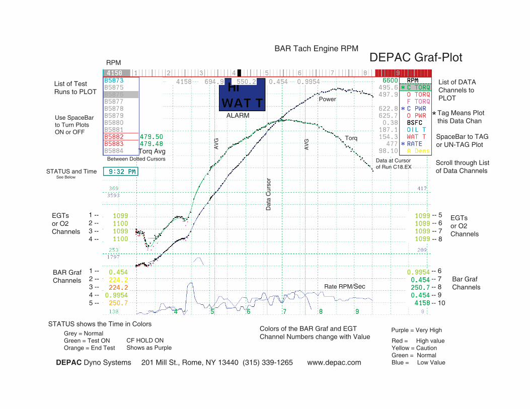
RPM
BAR Tach Engine RPMDEPAC Graf-Plot
List of Test Runs to PLOT
Use SpaceBar to Turn Plots ON or OFF
STATUS and TimeSee Below
1 --2 --3 --4 --
EGTsor O2Channels
1 --2 --3 --4 --5 --
BAR GrafChannels
Torq AvgBetween Dotted Cursors
Rate RPM/Sec
Power
Torq
Dat
a C
urso
r
AV
G
AV
G
STATUS shows the Time in ColorsGrey = NormalGreen = Test ONOrange = End Test
CF HOLD ONShows as Purple
DEPAC Dyno Systems 201 Mill St., Rome, NY 13440 (315) 339-1265 www.depac.com
Colors of the BAR Graf and EGTChannel Numbers change with Value
Red = High valueYellow = CautionGreen = NormalBlue = Low Value
Purple = Very High
Data at Cursorof Run C18.EX
List of DATAChannels toPLOT
Tag Means Plot this Data Chan*
SpaceBar to TAGor UN-TAG Plot
Scroll through Listof Data Channels
-- 5-- 6-- 7-- 8
EGTsor O2Channels
-- 6-- 7-- 8-- 9-- 10
Bar GrafChannels
ALARM
12
DEPAC Dyno Systems 201 Mill St. Rome NY 13440 (315) 339 [email protected] www.depac.com
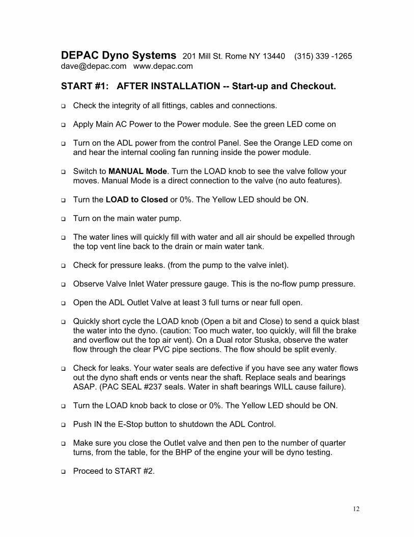
START #1: AFTER INSTALLATION -- Start-up and Checkout.
Check the integrity of all fittings, cables and connections.
Apply Main AC Power to the Power module. See the green LED come on
Turn on the ADL power from the control Panel. See the Orange LED come onand hear the internal cooling fan running inside the power module.
Switch to MANUAL Mode. Turn the LOAD knob to see the valve follow yourmoves. Manual Mode is a direct connection to the valve (no auto features).
Turn the LOAD to Closed or 0%. The Yellow LED should be ON.
Turn on the main water pump.
The water lines will quickly fill with water and all air should be expelled throughthe top vent line back to the drain or main water tank.
Check for pressure leaks. (from the pump to the valve inlet).
Observe Valve Inlet Water pressure gauge. This is the no-flow pump pressure.
Open the ADL Outlet Valve at least 3 full turns or near full open.
Quickly short cycle the LOAD knob (Open a bit and Close) to send a quick blastthe water into the dyno. (caution: Too much water, too quickly, will fill the brakeand overflow out the top air vent). On a Dual rotor Stuska, observe the waterflow through the clear PVC pipe sections. The flow should be split evenly.
Check for leaks. Your water seals are defective if you have see any water flowsout the dyno shaft ends or vents near the shaft. Replace seals and bearingsASAP. (PAC SEAL #237 seals. Water in shaft bearings WILL cause failure).
Turn the LOAD knob back to close or 0%. The Yellow LED should be ON.
Push IN the E-Stop button to shutdown the ADL Control.
Make sure you close the Outlet valve and then pen to the number of quarterturns, from the table, for the BHP of the engine your will be dyno testing.
Proceed to START #2.
13
DEPAC Dyno Systems 201 Mill St. Rome NY 13440 (315) 339 [email protected] www.depac.com
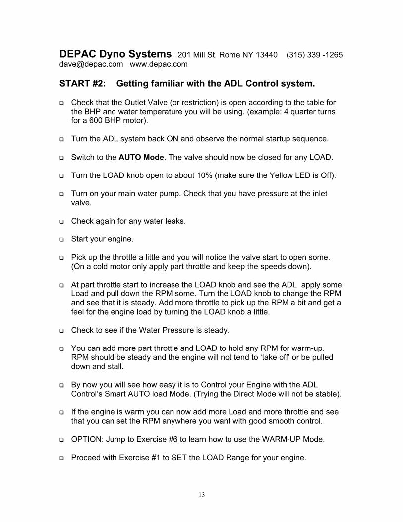
START #2: Getting familiar with the ADL Control system.
Check that the Outlet Valve (or restriction) is open according to the table forthe BHP and water temperature you will be using. (example: 4 quarter turnsfor a 600 BHP motor).
Turn the ADL system back ON and observe the normal startup sequence.
Switch to the AUTO Mode. The valve should now be closed for any LOAD.
Turn the LOAD knob open to about 10% (make sure the Yellow LED is Off).
Turn on your main water pump. Check that you have pressure at the inletvalve.
Check again for any water leaks.
Start your engine.
Pick up the throttle a little and you will notice the valve start to open some.(On a cold motor only apply part throttle and keep the speeds down).
At part throttle start to increase the LOAD knob and see the ADL apply someLoad and pull down the RPM some. Turn the LOAD knob to change the RPMand see that it is steady. Add more throttle to pick up the RPM a bit and get afeel for the engine load by turning the LOAD knob a little.
Check to see if the Water Pressure is steady.
You can add more part throttle and LOAD to hold any RPM for warm-up.RPM should be steady and the engine will not tend to ‘take off’ or be pulleddown and stall.
By now you will see how easy it is to Control your Engine with the ADLControl’s Smart AUTO load Mode. (Trying the Direct Mode will not be stable).
If the engine is warm you can now add more Load and more throttle and seethat you can set the RPM anywhere you want with good smooth control.
OPTION: Jump to Exercise #6 to learn how to use the WARM-UP Mode.
Proceed with Exercise #1 to SET the LOAD Range for your engine.
14
Exercise 1: Setting the LOAD RANGE of the ADL Control System.
Purpose: Adjust the ADL Control to work with your Dyno, Engine, and Water system.This will result in a good range of control using the LOAD Knob. Changing the Inletwater pressure has the same affect as changing the Valve Setting Scale. Check if youneed more or less water pressure. Make sure the water pressure is Steady to full load.Summary: The ADL System can work with a very wide range of dynos and engines.The FIRST Step in using the new system is to SET the OUTLET Flow Valve to theBHP range of your test engine. This sets the Water flow rate to match the powerabsorbed and so keeps the internal water temperature consistent. 2nd Step is to adjustthe Load range control for the engine being tested and your water supply pressure.Once a setting is found then you can record the scale for future reference and alwaysreturn to the exact same setting. The object is to have the LOAD knob look similar to theTach indicator so that it's easy to estimate a LOAD RPM just by pointing the LOAD knoblike the Tach indicator. This is a coarse approximation but useful for initial setting.Turn ON the ADL system and see that the self-ON-test is completed. The valve shouldmove to open and then be closed when ready. Turn ON the water pump/supply.Start with a fully warmed up engine. You should have a rough idea for the RPM for peakengine torque. You need a flat blade screw driver to adjust 100% Load Pot.
1. The OUTLET Valve MUST be SET using the BHP Table First.2. Check that Mode switch is set to AUTO-Stable and Turn ON ADL System.3. Turn the LOAD knob to 50%, pointer straight UP. (valve remains closed)4. Start your engine and turn ON the water pump.5. Slowly pick up the throttle and as the RPM picks up to about the torque peak.6. Adjust the Set % Full Load pot with screwdriver so that at full throttle you are
at engine’s torque peak. (Note: This trim adjustment jumps in 1 % steps).7. Return throttle to idle and then pickup full throttle again and see if the engine
Holds smoothly at the same set RPM Load. It should if everything is right.You have just scaled the ADL system to your engine, dyno, and water pressure. Pushthe SET ALT button and record the Number in the left LED window. When you weredoing Step 6 you noticed that the engine speed stepped as you slowly turned theSet % Full Load pot. The adjustment jumps in 1 % steps, like going from 34% to 35%,so you can always return to the exact same setting in the future.This setting will work with all engines with similar Torque curves. You will run with thisone scale setting for similar engines. If you want to test a much larger or smaller motorthen you may want to set the Set % Full Load scale to a different number. This Numbersets the Scale, or effect, of the large LOAD Knob for different size or type engines.Now the LOAD knob position is very similar to the RPM reading on the TACH indicator.It will be very easy to Quickly Estimate a starting RPM just by pointing the LOAD knoblike the TACH needle. Note that this is just a rough approximation. Another advantageto setting the LOAD Scale this way is that you have a Similar range of knob adjustmentfor fine setting the LOAD for your smallest to largest engines.
15
DEPAC Dyno Systems 201 Mill St. Rome NY 13440 (315) 339 [email protected] www.depac.com
Exercise 2: Use of the MANUAL or DIRECT Valve Mode:Purpose: To show that while in the MANUAL, or Direct Mode, the LOAD knob is aDirect connection to the Inlet valve. It has NO Auto-Stability and is exactly thesame as your original Hand Control valve. It is sometimes useful to just open andclose this valve to purge water through the dyno or test the valve movement.
When the LOAD Knob is turned to CLOSE (0%) the valve ISFully closed with an 0-Ring self wiping bubble tight seal.
Summary: The Actual Valve opening depends on the Load Range set in lesson 1. TheActual Valve Opening will usually be much less than the LOAD Knob % Setting. ThisRatio or Scale is adjusted by the SET% Full LOAD Pot.
Turning the LOAD Knob to Full Open (100%) will normally open the actual valve to lessthan 50% open or about 30 degrees open for the butterfly valve.
Exercise: The Motor and Water pump is OFF, The ADL System is ON.
1. Flip the Mode Switch to MANUAL2. The Valve will jump to an opening set by the current LOAD Knob %.3. Turn LOAD knob to Closed and check that the valve is closed, yellow LED On.4. Turn the LOAD Knob to 100% and see the Valve move to open, which will
generally be less than half open, set by Lesson 1 range setup.5. Turn the LOAD Knob quickly and see how fast the valve can follow your
movements. The valve will respond very quickly to your inputs.6. Switch back to AUTO Mode and see the valve immediately close and remains
closed no matter the LOAD Knob setting. (leave in AUTO Mode for tests).
You can Run your dyno in the Fully MANUAL Mode but it would offer no realadvantage over what you had before when using your hand control valve.If you turn the water pumps ON you can use the MANUAL mode to blast waterthrough your dyno for function testing, like for testing for leaks. When the engine isnot running, the dyno can fill with water very quickly and blow water out the top airvent.
Note:The Direct Valve Mode is NOT used for normal dyno testing. Thismode is just as unstable and difficult to use as your original handcontrol of the dyno.
Please Use the AUTO-Stable Mode for all your dyno testing.
16
DEPAC Dyno Systems 201 Mill St. Rome NY 13440 (315) 339 [email protected] www.depac.com
Exercise 3: Sweep Tests by Turning the LOAD Control knobThe ADL Control System should be ranged to Load your engine in Lesson 1.Purpose: To demonstrate that the LOAD Knob can smoothly control EngineRPM over a very wide range, especially at speeds where you could never holdthe engine before with the manual control valve. This also demonstrates theStability and easy use of the ADL system in the AUTO/Stable mode doing anADL 'manual sweep'. Also use the LOAD knob to feel the engine's torque curve.1. Turn ON the water pump.2. Set the LOAD Knob to an approximate Starting % dial or estimated RPM.3. Set the UP-Stop-DWN switch to the Stop/HOLD position. (no sweep).4. Smoothly add throttle to full and see where the engine RPM stabilizes.5. Make any LOAD adjustments to set your desired RPM. (Note LOAD dial %).6. If you are Recording this test, Hold the test Switch ON. (No Load Sweep).7. Now Slowly and Smoothly turn the LOAD Knob to raise, or lower, the RPM.8. When test sweep is done release the test Switch and bring throttle to idle.9. Repeat the above with different Start and End LOAD points, Up or Down.
This is not the recommended method of sweep testing because the operator cannever turn the LOAD Knob the same each time. The ADL Controlled AUTOSweep is Very consistent and repeatable, with an enhanced ‘feel’ for the engine.See Next Exercise 4 for the Recommended Sweep Mode:Use the UP - Stop - DWN Switch to have the internal processor change theLOAD at a very smooth and repeatable Rate. (Set by the RATE knob).The UP - Stop - DWN Switch works with an external push to close switch toCommand the sweep. This uses the same Push-to-Test switch used by theDEPAC instrumentation system. If you don’t have an Advanced DEPAC Systemthen we provide the ADL system with bare wire leads to connect to your TestSwitch and Tach signal inputs.
Note: If your engine has a very steep torque rise coming up on the cam, or pipe,there may be a very natural speed oscillation (caused by the steep torque rise).The normal oscillation will be smooth and any normal sweep Up or Down throughthis sharp region will be generally smooth and natural.
17
DEPAC Dyno Systems 201 Mill St. Rome NY 13440 (315) 339 [email protected] www.depac.com
Exercise 4: Automatic LOAD Sweeps with a Remote Test Switch.
ADL System should be ranged to your engine in Exercise 1.
Purpose: To demonstrate the Auto Sweep Mode using the UP-Stop-DOWNtoggle. A remote test switch commands a Load Sweep at a Rate set by theRATE Control. If the Auto Sweep is in the HOLD position the LOAD will notchange when you push the Remote Test Switch (use for a Static Pull).
Start and warm-up the engine. You can use the LOAD knob and Throttle to put apartial load on the engine. Use either the LOAD Knob or throttle to change RPM.(Also see WARM-UP Mode exercise #6).
1. Push your remote test switch to Check if the Green (T) LED comes on.
2. Set the LOAD Knob to an approximate Starting % dial or estimated RPM.
3. Set the Load Sweep toggle to either the sweep UP or DWN position.
4. Set the RPM knob to its lowest point 1000 RPM. (See Note below)
5. Smoothly add Full throttle and the engine will come up and Hold an RPM.
6. Make any LOAD adjustments to set your desired RPM. (Note LOAD dial %).
7. Close the TEST Switch and the Load starts to sweep either UP or DOWN.
8. During the Sweep you can change the UP-Stop-DOWN Switch at any time.
9. Release the Test Switch anytime to end sweep. Load returns back to Start.
10. Now You can pull back the throttle to idle.
NOTE: Setting the RPM Control Knob. You can use the RPM Knob to Set anEnd Point. The sweep will automatically stop after Exceeding the Set RPM Limit.Example: Start an UP Sweep at 4000 RPM and set the RPM control to 7000RPM (70 displayed). As the engine sweeps past 7000 RPM the LOAD SweepStops and holds the LOAD just above 7000 (#1 Red LED comes ON). It will holdhere as long as you want. Release the Test Switch and the LOAD returns back tothe start point of 4000 RPM.If you do not want to use the RPM Limit feature, just set the RPM outside theexpected speed range and You then control the end of sweep point with the TestSwitch. Also if you set the RPM Control to a low value, the limit is also ignored.NOTE: Changing Sweep Direction during a TEST Sweep. During a testsweep the UP-Stop-DWN Toggle can be changed anytime for any combinationof sweeps or Steady states, while the Remote test switch is closed. Releasingthe Test Switch will always return the Load to the Start point.
18
Exercise 5: Setting the Range of the Load Sweep RATE Control.Purpose: To range the ADL RATE Control to Sweep the LOAD to the testingneeds of your engine. Set a mid-position of the RATE control Knob so you canlatter adjust up or down as needed. You can change the RATE during a sweep.Summary: The ADL System can work with a very wide range Sweeps ranging formseconds to several minutes. You need to adjust the Set MAX Rate Trim Pot to matchyour sweep requirements. The ADL System sweeps the LOAD with stability and youwill see a natural and smooth RPM sweep of the engine. You cannot set an RPM/Secrate as you can with conventional dynos but the ADL Load RATE control is infinitelyvariable and can be changed during the sweep. Sweeps can be closely fine-tuned.The Sweep UP-STOP-DWN Toggle is used in conjunction with a Remote TestSwitch. If you have the Toggle in the STOP/Hold position and you push the TestSwitch the ADL system will Hold the engine at the same steady RPM. If you have theToggle in either UP or DWN, and you push the Test Switch, the ADL will start tosweep at a smooth LOAD change Set by the RATE Knob.Complete Exercise 1 to Scale the LOAD range to your engine and dyno.Have your engine warmed-up and ready for a test sweep. The ADL system andpumps should be ON. Have a flat blade screw driver ready for adjustment. Youshould have a remote Sweep Test pushbutton, preferably on your throttle. The TestSwitch will Command the LOAD to sweep UP, DWN, or Hold Steady LOAD1. Set the RATE Knob to 5 on the scale. (A mid-point for latter fine adjustments)2. Set a Starting LOAD, for an approximate starting RPM. (see exercise #1)3. Make sure that the RPM control is set either below your start RPM or above your
expected end RPM point. (RPM is on the Right LED display).4. Switch the Sweep Mode Toggle to UP.5. Pick-up the throttle to full and adjusting the LOAD knob as needed to Start RPM.6. Hold the Sweep Test button down and the LOAD will start to Sweep smoothly UP
(set in #4). Observe the Rate of change of the Engine RPM.7. Use the screwdriver to adjust the Set MAX Rate Pot to increase or decrease the
sweep rate you want. This will set a Middle point for the RATE Knob.8. Release the Test Button to end the sweep. This will cause the Engine RPM to
jump quickly back to the Start LOAD point. Pull back the throttle to idle.You have just scaled the Load Change RATE Knob to your testing needs either a fastsweep for a drag race engine or a slower sweep for a circle track race engine.Set MAX Rate even slower for Marine and Diesel engines. Rate can range can befrom 10 minutes down to seconds (non-linear adjustment).The LOAD sweeps are natural and will Smoothly speed up when coming up on thecam. If you want, you can turn the RATE Knob down to slow the rate when coming upon the cam and increase the sweep rate at the top end. If everything is working rightwith your whole test the sweep rate should be smooth and natural.
19
DEPAC Dyno Systems 201 Mill St. Rome NY 13440 (315) 339 [email protected] www.depac.com
Exercise 6: Warming up the Engine:WARM-UP Mode. Break-In Mode.
NOTE: Engine dynos always have torsional resonances at Unkown RPMs.Every engine dyno will have different dyno resonant Speeds, with can bedestructive. Holding the engine at a resonant RPM could cause very high +/-torque stress and can eventually lead to catastrophic failure over time (fatiguedamage). Broken driveshafts are a very common result of this fatigue stress.These destructive oscillations have nothing to do with dyno load, and can occurwith No Brake Load applied. With heavy flywheels you can have engine damage.The Only defense from damage with torsional resonance is to constantly change theRPM, so as to avoid long exposures at these destructive resonant RPMs.Purpose: To use the ADL to help warm the engine up to operating temperaturewithout the dangers of damage from torsional resonant stresses. To apply a Loadto the engine, at part throttle, at a low warm-up or break-in RPM. The constantchanging of engine Speed will greatly reduce any long-term fatigue damage fromany destructive torsional resonance’s on driveshafts and engine internals.
Auto Warm-up (or Break-in) Mode1. Add part throttle and set LOAD knob to a Warm-up (break-in) Start RPM.2. Turn the RPM Knob to a lower speed you want as a lower End RPM.3. Turn ON the Warm-Up Switch and the ADL will start quickly sweeping down to
the RPM End point, and then back up to the Start point, continuously. Turn theRATE Knob to change how quickly the engine sweeps up and down.
4. Switch OFF when done and the RPM will return to the start point set in #1.5. You can either pull the throttle back to idle or proceed to do a test sweep.Note: You can hold down the DEPAC test switch to have a test average record ofthe warm-up (break-in) process. Also you can watch the record pattern of MachineGun dots on the DEPAC LINK3 grafplot screen.
After you Start the WARM-UP Mode the Upper Start RPM is Locked in, but youcan re-adjust the LOAD setting and the Lower RPM setting. Also you can changewarm-up sweep rate using the RATE Knob.
NOTE: When you first turn on the WARM-UP Mode the ADL will Ignore any RPMknob setting that happens to be set Above your Start RPM point (Step #1). It willthen automatically Set a lower Default RPM sweep limit that's ½ the Start RPM.
20
Exercise 7: Using the Speed HOLD (Mapping) ModePurpose: The Speed HOLD Mode is intended for mapping an electronicengine management system. It is a very simple speed control that constantlyadjusts the LOAD to Hold a set RPM. When you change the throttle, mixture, orignition, the system will slowly adjust the Load to return any changed RPM backto the precise set-point. You can set a Speed Hold Speed in precise 100 RPMincrements from 1,000 RPM to 12,000 RPM. Use ONLY for Mapping.Operation: The Speed HOLD Mode must be locked, or initialized, before it canfunction in the Speed Hold mode. The right LED display shows the currentsetting (x100 RPM) and is controlled by the RPM Knob. Best to set a low RPMset-point to initialize this Mode. The valve starts closed and will remain closed aslong as the engine speed is less than the set-point. You need to add enoughthrottle so the RPM is above the set-point to initialize. Then the system will detecta speed error and start to open the valve to compensate. It may take severalseconds for the system to take control of the engine and bring the RPM downand hold it at the Initial set-point RPM. Watch the LOAD Number in the left LEDdisplay change as the ADL Control changes in response to the speed error.
Caution: The ADL Speed Hold mode MUST be First slowly INITIALIZED.Note: Open the throttle slowly when initializing the Hold Mode . The Valve is Closed Until the engine speed exceeds the Set RPM.1. Set the LOAD Knob to Zero. The yellow #3 LED indicates the Hold Mode ON.2. Set the RPM Knob to a Low to Mid Start Speed.3. Slowly add throttle to about 500 RPM above your Set Start RPM and wait.4. You will see the left Load Digit display start to increase as the valve opens.5. After a few seconds the ADL pulls the Speed Down to your Selected Start
RPM point. The #4 Green LED will flicker on/off when the Engine Speed iswithin 10 RPM of the Start/Set-point. The Load number digit is now steady.
6. The Speed HOLD Mode is Now Initialized and the ADL will hold RPM.7. Now make small step Changes like bump the throttle, or change the mixture
or timing. After a few seconds the ADL system should lock back to set RPM.8. You can now change the RPM Knob to set other Speeds in 100 RPM steps.9. Make changes in steps and then wait till the ADL is back on Lock. -- Repeat.10. You can also begin a Standard Load Sweep test at any time (UP-Stop-DWN).11. When done just slowly pull back the throttle. The valve will close.12. You can also cancel the Speed HOLD-Mode by turning the LOAD knob
Open until it over-rides the control of the Valve and pulls the motor down. TheYellow LED turns Off and you now have complete control with the LOAD Dial.
Any Flicker of the #4 Green LED indicates how smooth the engine is running.After the system is Locked onto the Hold-point speed you can then make anyreasonable changes you want and the Speed Hold Mode will automaticallychange the LOAD to hold the set RPM. Make any changes in steps and then waita few seconds for the system to respond. You can make a Torque Sweep, or aStatic test, at any time and the system will respond to the UP-STOP-DWNswitch. Each sweep will be a Smart Load Control Mode sweep and whencompleted the system will revert back to the Start RPM in Speed Hold Mode.
21
DEPAC Dyno Systems 201 Mill St. Rome NY 13440 (315) 339 –[email protected] www.depac.com
Exercise 8: DEPAC Inertia Correction Factor -- Making Torque Loops.
Purpose: Use the LOAD Knob to rapidly cycle the Torque Load to create Loops of DEPACMachine Gun (MGun) Dots used to set the Inertia correction. This uses a unique Advancedfeature of DEPAC LINK version 3 system to set the inertia correction after the tests.DEPAC Version 3 system can record and playback Torque vs. RPM MGun Dots used to testand set the DEPAC Inertia Correction Factor. The engine is loaded at full throttle at the RPMyou want to test the inertia. (Note: On some dynos like the Stuska® the Internal brake inertiacan change with the amount of water inside the brake). The Load is then quickly changed upand down to create a high +/- RPM/second sweep around the Steady Load point. With Noinertia correction the Torque MGun dots will plot in a counter-clockwise loop. The goal is tohave a large vertical loop pattern of dots so that when entering an Inertia correction numberthe sweep Up & Down dot Loops will be on the same curve, thus canceling the inertia error.
Make the Loop Test: We assume you have a DEPAC version3 system.1. The engine is warmed and ready to test.2. Go to the GrafPlot screen to view the Machine Gun (MGun) Torque dots.3. Set the UP/DWN switch to HOLD/Stop.4. Start with the DEPAC Inertia Setting of Zero to enhance the Torque Looping action.5. Set a LOAD so the engine throttles up a Speed between peak torque and peak power.6. Push the DEPAC Test Switch to record the MGun Dot loops.7. Roll the LOAD Knob Up and Down to make these torque loops. Only sweep 1000 RPM (or less) and try to get a Large change in +/- RPM/Sec to get large vertical torque loops.8. Release the Test Switch and throttle back and stop the engine.
Set the Inertia Correction: Use Vers3 to playback the test on the GRAF-Plot screen.1. Use the Insert Key to Playback the MGun dots on the Graph Screen.2. Use the Letter (I) key to pop-up the Inertia Set menu.3. Enter an estimated Inertia Correction Number (Like 0.10).4. Replay the MGun dots and observe any reduced size of the inertia error loops.5. Hit the F8 key (twice) to clear the old MGun dots and redraw the GrafPlot screen.6. Find a number that eliminates any looping (with the Red and white Dots are mixed evenly).
Note: An Over correction will cause the Dot loops to rotate clock-wise with the Red Dots Belowthe White Dots. An Under Correction will loop the Red Dots ABOVE the white dots.
Note: The remaining pattern of MGun dots represent the engine's torque scatter.Note: To Re-Draw the Screen and erase the MGun dots by hit the F8 key twice.Note: Use the Space-Bar to turn ON-OFF test run Data Curves and MGun dots.
22
DEPAC Dyno Systems 201 Mill St. Rome NY 13440 (315) 339 [email protected] www.depac.com
Exercise 9: The Emergency Shut-Down Feature:
Also for a Clean Cut for a plug check:The RED turn Power ON and OFF button will function as an Emergency Stop, ifyou use the external ignition (and/or Fuel Pump) relay. If you use this relay theADL system needs to be ON before you can turn On the Ignition (or fuel pumps).When you turn OFF the ADL system by pushing the Emergency Stop button,and the engine is not running, the system just turns itself Off. If the Engine isRunning and you hit this Button the Valve opens and floods the dyno and theexternal relay kills the ignition (and fuel pump). The engine should stop veryquickly. When the system sees that the engine is stopped it will then close thevalve and then turn itself Off.You should have the External Relay wired to cut the ignition and/or fuel pumps.1. Start the engine.
2. Pickup the throttle a little and apply a little load.3. Now Hit the Emergency STOP button4. The engine should stop very quickly.5. The valve should close and the ADL system shuts itself Off.Its good practice to occasionally test this feature, under controlled conditions, sothat you don't have to think about what to do if a real Emergency occurs.The normal Emergency STOP Action is to pull back on the throttle while hittingthe Emergency stop button.If you do not use the External Ignition Cut-off relay then the engine may continueto run at low RPM with the brake full of water. The brake itself will Not stall theengine. The ADL system will remain ON (and at full valve open) as long as theengine is still running. When you do stop the engine the valve will automaticallyclose and turn the system off.
23
DEPAC Dyno Systems 201 Mill St. Rome NY 13440 (315) 339 [email protected] www.depac.com
Exercise 10: RESET the Control Valve.NOTE: Every time you Turn ON the ADL system it will automatically cycle thevalve to find its Reference Position (Closed or Open, depending on Dyno).
Purpose: To demonstrate how to Reset the ADL System if the Valve losses itsReference Position while the engine is running or stopped.
Summary: On Power-up the ADL Control system moves the valve to find itsReference Position. There is a magnetic sensor imbedded in the plate for thispurpose. All movement after this is relative to this Closed Reference point.Some times the valve may lose track of its absolute position and therefore be at thewrong opening. So, if the Engine does not come up to the expected RPM for a LOADsetting then maybe the valve has lost its reference. It's easy to check and RESET theValve. This should not happen very often, if at all.
Whenever the engine is Off the System will check itself Automatically for its referenceposition and, if not, will Reset the Valve automatically.
So by turning off the engine will cause the ADL Control to self-check its reference.
Reseting the Valve while The Engine is Running and ADL is ON:Exercise Situation: Say We suspect that the system has lost its Valve ReferencePoint and we want to check and Reset the Valve, if needed.Method 1: Pull the throttle back to Idle and then turn the LOAD Knob to Zero for amoment (see the Yellow 'S' LED come on) and then turn it back to your normalsetting. This commands a Valve Reset. You can then pick up the throttle again andsee if that made any difference in the operating load point.Method 2: Stop the engine. The system will self-test and Reset the Valveautomatically, if needed, without you touching the ADL panel. Restart the engine andcontinue your testing.
Both Methods will cause the ADL System to check and reset the valve to itsReference position, if needed, while the system is still powered ON.
Note: When the engine is not running, you can always push the system OFF, thenback ON, to re-initialize the system and reset the inlet valve to the closed position.
24
DEPAC Dyno Systems 201 Mill St. Rome NY 13440 (315) 339 –[email protected] www.depac.com
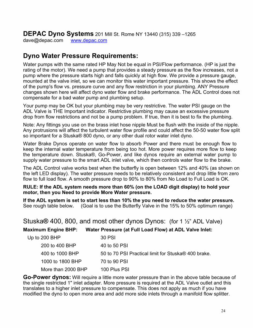
Dyno Water Pressure Requirements:Water pumps with the same rated HP May Not be equal in PSI/Flow performance. (HP is just therating of the motor). We need a pump that provides a steady pressure as the flow increases, not apump where the pressure starts high and falls quickly at high flow. We provide a pressure gauge,mounted at the valve inlet, so we can monitor this water important pressure. This shows the effectof the pump's flow vs. pressure curve and any flow restriction in your plumbing. ANY Pressurechanges shown here will affect dyno water flow and brake performance. The ADL Control does notcompensate for a bad water pump and plumbing setup.Your pump may be OK but your plumbing may be very restrictive. The water PSI gauge on theADL Valve is THE Important indicator. Restrictive plumbing may cause an excessive pressuredrop from flow restrictions and not be a pump problem. If true, then it is best to fix the plumbing.Note: Any fittings you use on the brass inlet hose nipple Must be flush with the inside of the nipple.Any protrusions will affect the turbulent water flow profile and could affect the 50-50 water flow splitso important for a Stuska® 800 dyno, or any other dual rotor water inlet dyno.Water Brake Dynos operate on water flow to absorb Power and there must be enough flow tokeep the internal water temperature from being too hot. More power requires more flow to keepthe temperature down. Stuska®, Go-Power, and like dynos require an external water pump tosupply water pressure to the smart ADL inlet valve, which then controls water flow to the brake.The ADL Control valve works best when the butterfly is open between 12% and 40% (as shown onthe left LED display). The water pressure needs to be relatively consistent and drop little from zeroflow to full load flow. A smooth pressure drop to 90% to 80% from No Load to Full Load is OK.RULE: If the ADL system needs more than 60% (on the LOAD digit display) to hold yourmotor, then you Need to provide More Water pressure.If the ADL system is set to start less than 10% the you need to reduce the water pressure.See rough table below. (Goal is to use the Butterfly Valve in the 15% to 50% optimum range)
Stuska® 400, 800, and most other dynos Dynos: (for 1 ½” ADL Valve)Maximum Engine BHP: Water Pressure (at Full Load Flow) at ADL Valve Inlet:
Up to 200 BHP 30 PSI200 to 400 BHP 40 to 50 PSI400 to 1000 BHP 50 to 70 PSI Practical limit for Stuska® 400 brake.1000 to 1800 BHP 70 to 90 PSIMore than 2000 BHP 100 Plus PSI
Go-Power dynos: Will require a little more water pressure than in the above table because ofthe single restricted 1" inlet adapter. More pressure is required at the ADL Valve outlet and thistranslates to a higher inlet pressure to compensate. This does not apply as much if you havemodified the dyno to open more area and add more side inlets through a manifold flow splitter.