DENTON VACUUM, INC. THE UNIVERSITY OF UTAH Job · • flange mounted bellows and linear actuator...
56
Tel: 609-439-9100 Fax: 609-439-9111 DENTON VACUUM, INC. THE UNIVERSITY OF UTAH Job #: 18097 SJ/20C E-BEAM EVAPORATION SYSTEM Denton Vacuu m, Inc. 1259 North Church Street, Moorestown, NJ 08057 February 1997
Transcript of DENTON VACUUM, INC. THE UNIVERSITY OF UTAH Job · • flange mounted bellows and linear actuator...
Tel: 609-439-9100
Fax: 609-439-9111
DENTON VACUUM, INC.
THE UNIVERSITY OF UTAHJob #: 18097
SJ/20CE-BEAM EVAPORATION SYSTEM
Denton Vacuu m, Inc.
1259 North Church Street, Moorestown, NJ 08057 February 1997
The University of Utah, Job # 18097Table of Contents
TABLE OF CONTENTS
Section
Denton Vacuwn, Inc.SJ/20C Evaporation System
Page
1.
2.
3.
INTRODUCTION
SAFETY WARNINGS
SYSTEM SPECIFICATIONS
1-1
2-1
3-1
3.13.23.33.43.53.63.73.83.93.103.10.13.10.23.10.3
Deposition Chamber . . . . . . . . . . . . . . . . . . . . . . . . . . . . . . . . . . . . .3-1Pumping System . . . . . . . . . . . . . . . . . . . . . . . . . . . . . . . . . . . . . . . .3-1Vacuum Gauging 3-2Electron Beam Source . . . . . . . . . . . . . . . . . . . . . . . . . . . . . . . . . . . .3-3Evaporation Source Shutter 3-3Substrate Heater 3-4Substrate Fixture and Stage Rotation . . . . . . . . . . . . . . . . . . 3-4System Control and Automation 3-4Utilities . . . . . . . . . . . . . . . . . . . . . . . . . . . . . . . . . . . . . . . . . . . . . 3-4Safety Standards 3-5Safety Interlocks .3-5Moving Parts ...........................................3-5Power Systems 3-5
4. SYSTEM OPERATION
4.1 Cold Start-Cryopump Regeneration 4-14.1.1 Cold Start-Cryopump Regeneration - Manual Mode 4-14.1.2 Cold Start-Cryopump Regeneration - Automatic Mode 4-24.2 System Pumping and Venting .4-34.2.1 Main Chamber Pumping - Automatic Mode 4-34.2.2 Main Chamber Pumping - Manual Mode 4-44.2.3 Main Chamber Venting - Automatic Mode 4-44.2.4 Main Chamber Venting - Manual Mode 4-54.3 Substrate Heat Control .4-54.4 Electron Beam Source Operation 4-64.4.1 Gun Control! XTC/2 Setpoint Control 4-64.5 Service Mode 4-7
- 1 -

The University of Utah, Job # 18097Table of Contents
TABLE OF CONTENTS
Section
Denton Vacuwn, Inc.SJ/20C Evaporation System
Page
5.
6.
no LIST
"SOFTWARE" INTERLOCKS
5-1
6-1
6.1 MKS 286 Convectron Setpoints 6-16.2 Mechanical Pump 6-16.3 Cryo pump 6-16.4 Chamber Rough Valve 6-16.5 Chamber Vent Valve 6-26.6 Mech. Pump Purge 6-26.7 Cryo Pump Purge 6-26.8 Cryo Pump Regen 6-36.9 Chamber Hivac Valve 6-36.10 Rotation . . . . . . . . . . . . . . . . . . . . . . . . . . . . . . . . . . . . . . . . . . . . . .6-36.11 Heat Power 6-46.12 Shutter .6-46.13 Shift Function 6-46.14 Auto Regen ' 6-46.15 Autopump 6-56.16 Autovent 6-5
7. TROUBLESHOOTING 7-1
7.1 Introduction . . . . . . . . . . . . . . . . . . . . . . . . . . . . . . . . . . . . . . . ....7-17.2 Basic Tool Requirements . . . . . . . . . . . . . . . . . . . . . . . . . . . . . . . . . .7-17.3 Vacuum System Control Rack ..............................7-37.4 PLC Controller Input/Output .. 7-47.5 Valves and Shutters 7-57.6 Rotation 7-87.7 Substrate Heat 7-97.7.1 SCR Controller 7-97.8 Summary 7-11
- 11 -

The University of Utah, Job # 18097Table of Contents
TABLE OF CONTENTS
Section
8. SPARE PARTS LISTS
9. ELECTRICAL SCHEMATICS (located in binder)
Denton Vacuum, Inc.SJ/ZOC Evaporation System
Page
r_
Description File NameSystem Flow Chart SYSFLOW.OWG-AInterlock , , PRO-INTL.DWG-AXTCj2 Control , PRO-XTC.OWG-APumps & Valves PRO-PUMP.OWG-APLC Rack Layout PRO-PLC.OWG-A~ PRO GbeW.DWG-A ---Rotation Control PRO-ROTA.OWGSweep Control PRO-SWP.DWGLow Voltage Contlo} ~
Power Distribution PRO-POWE.DWGGun Control PRO-GUN.OWG-AMKS Gauge Control , PRO-GAUG.OWG-ATC Gauge Control PRO-TC.DWG
.-Spattering CoIIlrnl PRO-SPU'f.DWG-A.Gr Series 275 Mini CeftveetfOft Vacuum Gauge PRQ GP.DWG
10. MECHANICAL DRAWINGS (located in binder)
Description NumberGeneral Arrangement & Floor Plan . . . . . . . . . . . . . . . . . . . . . . . .0-0058-190-002Baseplate Layout D-0058-190-1ooPoppet Valve Assembly ., 0-0004-001-008Air Piping Assembly C-0058-190-0 11Water Piping Assembly 0-0058-190-012Vacuum Piping Assembly 0-0058-190-010Shutter Drive Assembly 0-0084-020-061Rotation Assembly .0-0058-180-0143 kW Heater Assembly C-0084-012-1681.00" Dia. Rotory Motion Assembly B-0044-0 11-010
- 11l -

The University of Utah, Job # 18097Table of Contents
TABLE OF CONTENTS
Section
10. MECHANICAL DRAWINGS (cant'd)
Denton Vacuum, Inc.SJ/20C Evaporation System
Page
Description Number.38" Dia. Rotary Motion Assembly 8-0041-011-0030.25" Dia. Rotory Motion Assembly 8-0041-001-008
11. PREVENTIVE MAINTENANCE
11.1 Mechanical Pump . . . . . . . . . . . . . . . . . . . . . . . . . . . . . . . . . . . . . . 11-111.2 Deposition Chamber . . . . . . . . . . . . . . . . . . . . . . . . . . . . . . . . . 11-111.3 Cryopump Compressor 11-111.4 Cryopump 11-111.5 Pumping system . . . . . . . . . . . . . . . . . . . . . . . . . . . . . . . . . . . 11-1
12. EQUIPMENT LIST, VENDOR MANUALS& SERIAL NUMBERS (under separate cover)
APD-CryogenicsGas Lines
APD-CryogenicsTwo-Stage ExpanderSerial #: F0751 NH
APD-CryogenicsCold HeadSerial #: E7198
A1catel Vacuum ProductsUT2021 Rotary Vane PumpSerial #: 304414
8&8DC Motor
- IV -
Manual Provided
Manual Provided
Manual Provided
Manual Provided
The University of Utah, Job # 18097Table of Contents
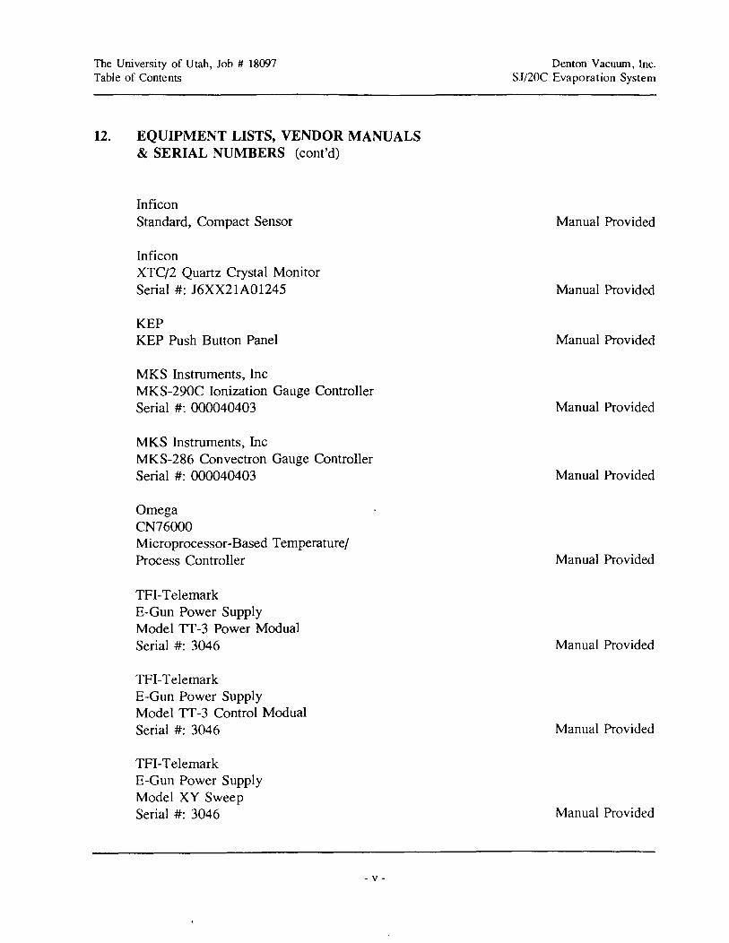
12. EQUIPMENT LISTS, VENDOR MANUALS& SERIAL NUMBERS (cont'd)
InficonStandard, Compact Sensor
InficonXTC/2 Quartz Crystal MonitorSerial #: J6XX21A01245
KEPKEP Push Button Panel
MKS Instruments, IncMKS-290C Ionization Gauge ControllerSerial #: 000040403
MKS Instruments, IncMKS-286 Convectron Gauge ControllerSerial #: 000040403
OmegaCN76000Microprocessor-Based Temperature/Process Controller
TFI-TelemarkE-Gun Power SupplyModel TT-3 Power ModualSerial #: 3046
TFI-TelemarkE-Gun Power SupplyModel TT-3 Control ModualSerial #: 3046
TFI-TelemarkE-Gun Power SupplyModel XY SweepSerial #: 3046
- v -
Denton Vacuwn, Inc.SJ/20C Evaporation System
Manual Provided
Manual Provided
Manual Provided
Manual Provided
Manual Provided
Manual Provided
Manual Provided
Manual Provided
Manual Provided

The University of Utah, Job # 18097Table of Contents
- VI -
Denton Vacuum, Inc.SJ/20C Evaporation System

The University of Utah, Job # 18097 Denton Vacuum, Inc.Introduction SJ/20C Evaporation System
1. INTRODUCTION
The Denton Vacuum SJ/2OC Optical Coating System is designed for either thin filmproduction or research. The SJ/20C configuration provides easy access to substrates, sources, and
instrumentation while maintaining excellent pumping characteristics. This system is designed to
simplify the geometries necessary for the coordination of multiple source depositions.
Because Denton uses the finest available subsystems and components, the system is highly
reliable and durable. The system's inherent flexibility allows for the operation of one electron
beam gun, a 3 kW substrate heating system, and the ability to rotate the substrate. The SJ/20Cis semi-automatic controlled by a General Electric 90-30 Programmable Logic Controller (PLC).
The system's power supplies and instrumentation are installed in a control cabinet conveniently
located next to the chamber for easy observation and operation.
The system offers the user a myriad of thin film process possibilities. However, it isimportant to note that with all of this system's potential there exists safety considerations.
Individuals who are to operate, service or maintain this system should familiarizethemselves with this manual.
1-1

The University of Utah, Job # 18097Introduction
1-2
Denton Vacuum, Inc.SJ/20C Evaporation System
The University of Utah, Job # 18097Safety Warnings
2. SAFETY WARNINGS
Denton Vacuum, Inc.SJ/20C Evaporation System
This vacuum deposition system is comprised of a number of complexsubsystems.
LETHAL VOLTAGES, HIGH TEMPERATURES, HIGH PRESSURESAND POWERFUL MECHANICAL DRIVE MECHANISMS AREPRESENT THROUGHOUT THE SYSTEM.
Every attempt has been made to safeguard operating and maintenance
personnel. Interlocking of subsystems provides a high degree of operator safety.
SYSTEM/SOFTWARE INTERLOCKS SHOULD NEVER BEDEFEATED UNLESS SERVICING OF THE SYSTEM REQUIRESTEMPORARY INTERLOCK OVERRIDES. HARDWIRED SAFETYINTERLOCKS MUST NEVER BE- DEFEATED.
All safety/software interlocks should be returned to operational status when
problems have been corrected.
Operating and maintenance manuals have been provided and should be
thoroughly understood before any operations are contemplated.
THE·· SYSTEM SHOULD BE OPERATED
ONLY BY PERSONNEL WITH PROPERTRAINING AND PROCESS EXPERIENCE.
2-1

The University of Utah, Job # 18097Safety Warnings
2-2
Denton Vacuum, Inc.SJ/20C Evaporation System

The University of Utah, Job # 18097Summary Specification
3. SUMMARY SPECIFICATION
3.1 DEPOSITION CHAMBER
Denton Vacuum, Inc.SJj20C Evaporation System
The vacuum chamber assembly is constructed entirely of electropolished, 304Lstainless steel and measures internally 20/1 wide x 29/1 deep x 28" high. The generousinternal height facilitates the introduction of substrates and substrate fixturing andminimizes the chance that spatter from an evaporant source will contaminate thesubstrates surface. All elastomeric seals used throughout the chamber are fabricatedfrom Viton.
The chamber is split on a vertical axis with a full opening door mounted on the front;providing complete, unrestricted access to the substrates and internal chambercomponents. The chamber door incorporates two-point articulating hinges to protectthe door o-ring from scuffmg and insure proper sealing.
3.2 PUMPING SYSTEM
The chamber is pumped through a. high conductance bellows-sealed poppet valvewhich is welded to the chamber's baseplate. This valve housing also incorporates thechamber's roughing and venting ports.
All components of the poppet valve are fabricated from 304L stainless steel.
The poppet valve is designed to facilitate maintenance through the incorporation of thefollowing features:
• removable seal plate (o-ring replacement)
• removable seal plate seating disk (customer refurbishment of sealing surface)
• flange mounted bellows and linear actuator (replacement of bellows)
High vacuum pumping is provided by an APD Cryogenics APD-8S cryopump with
an HC-4 Displex water cooled compressor. Initial chamber evacuation and cryopump
regeneration is accomplished by an Alcatel 2021 (17 cfm) two-stage, rotary vane
3-1
The University of Utah, Job # 18097Summary Specification
Denton Vacuum, Inc.SJ/2OC Evaporation System
pump. An oversized absorption trap and mechanical pump purge (dry Nz) capability
has been included in the foreline to effectively reduce backstreaming.
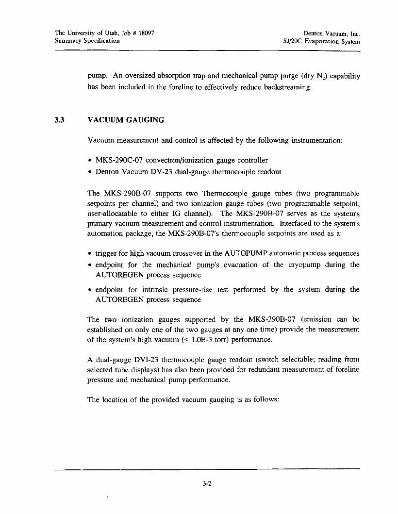
3.3 VACUUM GAUGING
Vacuum measurement and control is affected by the following instrumentation:
• MKS-290C-07 convectron/ionization gauge controller
• Denton Vacuum DV-23 dual-gauge thermocouple readout
The MKS-290B-07 supports two Thermocouple gauge tubes (two programmablesetpoints per channel) and two ionization gauge tubes (two programmable setpoint,user-allocatable to either IG channel). The MKS-290B-07 serves as the system'sprimary vacuum measurement and control instrumentation. Interfaced to the system'sautomation package, the MKS-290B-07's thermocouple setpoints are used as a:
• trigger for high vacuum crossover in the AUTOPUMP automatic process sequences
• endpoint for the mechanical pump's evacuation of the cryopump during theAUTOREGEN process sequence'
• endpoint for intrinsic pressure-rise test performed by the system during theAUTOREGEN process sequence
The two ionization gauges supported by the MKS-290B-07 (emission can beestablished on only one of the two gauges at anyone time) provide the measurementof the system's high vacuum « 1.0E-3 torr) performance.
A dual-gauge DVI-23 thermocouple gauge readout (switch selectable; reading fromselected tube displays) has also been provided for redundant measurement of forelinepressure and mechanical pump performance.
The location of the provided vacuum gauging is as follows:
3-2
The University of Utah, Job # 18097Summary Specification
Denton Vacuum, Inc.SJ/2OC Evaporation System
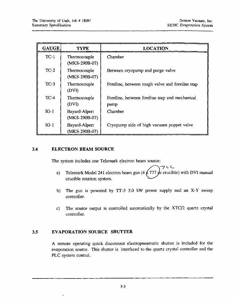
GAUGE TYPE LOCATION
TC-l Thermocouple Chamber(MKS-29OB-07)
TC-2 Thermocouple Between cryopump and purge valve
(MKS-29OB-07)
TC-3 Thermocouple Foreline, between rough valve and foreline trap(DVI)
TC-4 Thermocouple Foreline, between foreline trap and mechanical
(DVI) pump
10-1 Bayard-Alpert Chamber(MKS-290B-07)
10-1 Bayard-Alpert Cryopump side of high vacuum poppet valve
(MKS-290B-07)
3.4 ELECTRON BEAM SOURCE
The system includes one Telemark e~ectron beam source:
aJ Telemark Mode1241 electron beam gun (4 ~~C:;:c~le) with DVI manualcrucible rotation system. V'
b) The gun is powered by TT-3 3.0 kW power supply and an X-Y sweepcontroller.
c) The source output is controlled automatically by the XTC/2 quartz crystalcontroller.
3.5 EVAPORATION SOURCE SHUTTER
A remote operating quick disconnect electropneumatic shutter is included for theevaporation source. This shutter is interfaced to the quartz crystal controller and thePLC system control.
3-3
The University of Utah, Job # 18097Summary Specification
3.6 SUBSTRATE HEATER
a) One Denton 3.0 kW heater array.
3.7 SUBSTRATE FIXTURE AND STAGE ROTATION
Denton Vacuum, Inc.SJ/2OC Evaporation System
The SJ/20C is supplied with a single rotation, bearing-supported, rotary fIxture support.The shaft will be directly driven by a DC gear motor and attain a variable speed of 0to 27 rpm, via a potentiometer.
3.8 SYSTEM CONTROL AND AUTOMATION
• General Electric 90-30 programmable logic controller (PLC) with membrane-typeoperator interface.
• EEPROM memory backup.
• Valve control/sequencing, pump operation, and "soft" system interlocks (i.e.,non-safety related) controlled by the PLC.
• The following operating modes provided:- AUTOPUMP (automatic loadlock and chamber pumpdown to high vacuum
conditions),- AUTOVENT (automatic loadlock and chamber venting to atmospheric pressure),- MANUAL (permits manual (front panel) system operation and interruption of
in-process automatic system sequences), and- MAINTENANCE MODE (key-switch selectable from MANUAL mode; permits
all MANUAL MODE functionality, "soft" system valve interlocks disabled. All"hard" safety interlocks remain operational).
3.9 UTILITIES
Electrical:
Water:
Nitrogen:
208 VAC, 3-phase, 60 Hz, 5-wire, 75 amps.
15-20 l/min, 15-25 C, 3-4 bar differential between supply andreturn.
0.5 bar (Chamber venting)2.0 bar (Cryopump regeneration)
3-4
The University of Utah, Job # 18097Summary Specification
Denton Vacuum, Inc.SJ/2OC Evaporation System
3.10
3.10.1
3.10.2
3.10.3
SAFETY STANDARDS
SAFETY INTERLOCKS
• The system is equipped with a hardwired safety interlock system which fullyprotects operators and maintenance personnel from personal injury. The followinghardwired interlocks will be provided:- E-Gun Power Supply: Vacuum safety bellows switch, chamber door, chamber
thennocouple gauge setpoint and water flowswitch.- Heat Power: Vacuum safety bellows switch and chamber door.
• All hardwired safety interlock status are displayed to the system operator(s) at alltimes.
• All hardwired safety interlocks are duplicated by system controller "software"interlocks. In addition, all digital system events (eg., valve closure) are protectedby "software" interlocks.
MOVING PARTS
• Sliding surfaces and pinch points are fully guarded to prevent injury to operatorsand maintenance personnel.
• In the event of a power failure, all moving parts corne to a complete stop. Uponinitiating a restart cycle, all moving parts proceed to their horne position withoutdamage to the equipment or injury to operations and/or maintenance personnel.
POWER SYSTEMS
• In the event of an interlock dropout or power failure, all power to internal sourcesof energy (heater and sputter power supply) are interrupted. When power isrestored, or an interlock is satisfied, a hard, manual reset of the affected subsystemis required.
• High voltage devices, vacuum feedthroughs and inter-connecting cabling will beenclosed in water-tight enclosures (NEMA 4 rating or better).
3-5
The University of Utah, Job # 18097Summary Specification
Denton Vacuum, Inc.SJ/2OC Evaporation System
i
(\
(')
'/
/ r
,tq.(~'~_
V
T['I '
)
1/
! (~
'-'.. ;" I r
"1/v) f>ije.• I)
3-6
/
it)

The University of Utah, lob #: 18097Operation
4. SYSTEM OPERATION
4.1 COLD START-CRYOPUMP REGENERATION
Denton Vacuum, Inc.Slj20C Evaporation System
4.1.1 COLD START-CRYOPUMP REGENERATION - MANUAL MODE
1. Ensure that all utilities and process gases are installed and operational. Tum ONthe main system disconnect which is located on rear of the system's instrumentationcabinet.
2. Push the green START button located near the top of the instrumentation cabinet.At this point, power to the system will be applied.
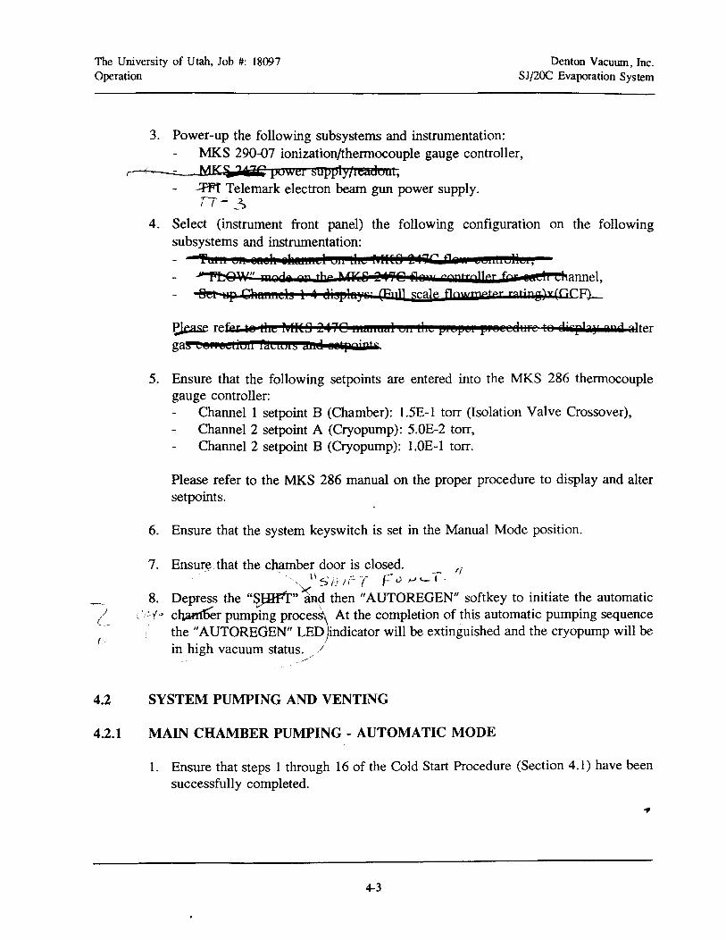
3. Power-up the following subsystems and instrumentation: .- MKS 290-07 iOnizatiOn,lth~le gauge controller,
/\1 (;1.,\ -( ;.:-----MKS -241C power supp1y.freadout, 61'" r 1J..-r-~-.~--- /,'- -~ ----.
7r", C'.~'-::---Wi Telemark electron beam gun power supply.'v (
4. Select (instrument front panel) the following configuration on the followingsubsystems and instrumentation:. / ~
Tum on each chanllel on the MI<.S.241C flow controller," FLOW" mode on the MKS.241C flow controller for each channel, _/Set up Channels 1-4 displays: (Full scale flowmeter rating)x(GCF). -_
Please refer to the MKS .247C·~ual on the proper procedure to display and altergas correction factors and setpoints.
5. Ensure that the following setpoints are entered into the MKS 286 thermocouplegauge controller:
Channel 1 setpoint B (Chamber): 1.5E-l torr (Isolation Valve Crossover),Channel 2 setpoint A (Cryopump): 5.0E-2 torr,Channel 2 setpoint B (Cryopump): 1.0E-l torr.
Please refer to the MKS 286 manual on the proper procedure to display and altersetpoints.
6. Ensure that the system keyswitch is set in the Manual Mode position.
7. Ensure that the chamber door is closed.
4-1

The University of Utah, Job #: 18097Operation
Denton Vacuum, Inc.SJj20C Evaporation System
I
4.1.2
8. Ensure that 20-40 psi dry nitrogen gas has been supplied to the cryopump purgevalve.
C}9. Open the cryopump purge valve (key pad labeled "PURGE VAUlE"); wait 3 hours.
/' ; /,'
10. Close the cryopump purge valve (key pad labeled "PURGE V1tL'tE!!).
11. Tum on the mechanical pump (key pad labeled "MECH PUMP"); wait 60 secondsand open the cryopump regen valve (key pad labeled "REGEN VALVE"); until thepressure indicated on MKS 286 thermocouple gauge channel 2 is less than 50millitorr.
L{~
12. Close the cryopump regen valve (key pad labeled "REGEN VALVEH
) and turn offthe mechanical pump (key pad'labeled "MECH PUMP").
13. If the channel 2 pressure reading does NOT rise above 100 mtorr in 60 seconds thepump is ready to be turned on. In this case please continue to operationalprocedure 14. Likewise, if the channel 2 pressure reading does rise above 100mtorr in 60 seconds the pump is NOT ready to be turned on. In this case pleaseclose the regen valve and return to operational procedure 10 but only purge thecryopump for 1 hour. If the cryopump fails this "60 second pressure rise test" 3times consecutively it is most likely a vacuum leak and should be leak tested beforecontinuing.
I1rzr' i
14. Tum on thecryopump (key pad labeled "tRYOPUMP") ; wait 3 hours and selectthe cryopump ionization gauge tube (key pad labeled "IG 1/2 SELECT"; Note whenthe led is on jQ1is selected) and turn on the gauge emission (turn off and then turn
I..;'orillle power to the MKS 290).
COLD START-CRYOPUMP REGENERATION - AUTOMATIC MODE
1. Turn ON the main system disconnect which is located on rear of the system'sinstrumentation cabinet; ensure that all utilities and process gases are installed andoperational.
2. Push the green START button located near the top of the instrumentation cabinet.At this point, power to the system will be applied.
4-2
The University of Utah, Job #: 18097Operation
Denton Vacuum, Inc.SJj20C Evaporation System
('/: f,'
(.
4.2
4.2.1
3. Power-up the following subsystems and instrumentation:MKS 290-07 ionization/thermocouple gauge controller,
r-"----=- MK 'ia217C power supply/Ieadout,.wr Telemark electron beam gun power supply.TT'- _2:>
4. Select (instrument front panel) the following configuration on the followingsubsystems and instrumentation:
'"fulIi en @fteh ilftMdIel 61£ MW f'fI~8 217G Vi conLiollOl,","' PLOW" mQdi QR We UKS 2..90 Alit'" controller for utlr Channel,~p Qftfthlleh 1 :4 eI3t'lft"s' (Full scale flowmeter ratjP8~x(GCF~
~ refer .8 the "fitS 2:4QC mwmal on the pepCI pfeee6tife te sisphr 2p d alterga~6"eeLiwr tauws Wiel !!liltpgjpts
5. Ensure that the following setpoints are entered into the MKS 286 thermocouplegauge controller:
Channell setpoint B (Chamber): 1.5E-l torr (Isolation Valve Crossover),Channel 2 setpoint A (Cryopump): 5.0E-2 torr,Channel 2 setpoint B (Cryopump): 1.0E-l torr.
Please refer to the MKS 286 manual on the proper procedure to display and altersetpoints.
6. Ensure that the system keyswitch is set in the Manual Mode position.
7. Ensure that the cbl:imber door is closed.._ 'I., "SHIFT f:"0 tJ<.-l·
8. Depress the "~"~d then "AUTOREGEN" softkey to initiate the automaticcl~r pumping proces~ At the completion of this automatic pumping sequencethe"AUTOREdEN" LED)indicator will be extinguished and the cryopump will bein high vacuum status. /
SYSTEM PUMPING AND VENTING
MAIN CHAMBER PUMPING - AUTOMATIC MODE
1. Ensure that steps 1 through 16 of the Cold Start Procedure (Section 4.1) have beensuccessfully completed.
4-3

The University of Utah, Job #: 18097Operation
Denton Vacuum. Inc.SJ/2OC Evaporation System
r'. -'<-! i
2. Depress the "SHIff'" and then "AUTOPUMP" softkey to initiate the automaticchamber pumping process. At the completion of this automatic pumping sequencethe "AUTOPUMP" LED indicator will be extinguished and the chamber will be inhigh vacuum status. ~ "'. ".
NOTE: If the "AUTOPUMP" softkey is depressed before the completion of theautomatic cycle (i.e., the autocycIe LED is still lit when the key is depressed)then the automatic cy~le will.be terminated and the, macl),ine will remain in thevalve state at which th~ ,termination was initiated!
4.2.2 MAIN CHAMBER PUMPING - MANUAL MODE
1. Ensure the Cold Start Procedure (Section 4.1) has been successfully completed.
2. Ensure that the system keyswitch is set in the Manual Mode position.
3. Ensure that the all system valves. are closed and tum off the gauge emission (tumoff the power to the MKS 290).
4. Turn on the mechanical pump (key pad labeled "MECH PUMP"); wait 60 seconds.
5. Open the chamber rough valve (key pad labeled "ROUGH VALVE"). Pump themain chamber until the pressure indicated on MKS 286 channel 1 is less than1.5E-l torr (150 mtorr).
6. Close the chamber rough valve (key pad labeled "ROUGH VALVE").II t-/i- 1/ A<- 1-'kilt.. ", II
7. Open the chamber hivac valve (key pad labeled "HJ..VAC VALVE").
8. Select the chamber ionization gauge tube (key pad labeled "IG 1/2 SELECf"; Notewhen the led is on IG1 is selected) and tum on the gauge emission (tum off andthen tum on the power to the MKS 290).
4.2.3 MAIN CHAMBER VENTING - AUTOMATIC MODE
1. Ensure that the system keyswitch is set in the Manual Mode position.
4-4

The University of Utah, Job #: 18097Operation
Denton Vacuum, Inc.SJ/2OC Evaporation System
Crv rJ2. Turn off all internal sources of energy~' DC F id:t, and heat).
.< IIt';; d ,.... <---/
3. Depress the "SHIFf'" 'and then "AUTOVJ;:NT" softkey to initiate the automaticchamber venting process. At the completion of this automatic venting sequence the"AUTOVENT" LED indicator will be extinguished and the chamber will be ventedto atmospheric pressure.
NOTE: If the"AUTOVENT" softkey is depressed before the completion of theautomatic cycle (Le., the autocycle LED is still lit when the key is depressed)then the automatic cycle will be terminated and the machine will remain in thevalve state at which the termination was initiated!
4.2.4 MAIN CHAMBER VENTING - MANUAL MODE
1. Ensure that the system keyswitch is set in the Manual Mode position.
711-fl.-2. Turn off -ttH'1fttemal sources oPetw'g¥ <0 power, gun high voltage and filament
power, J\£ glom power, ana lpw yg11iib f"~. pc, '-"'; ,E ..c:... "S...J '"'(')i.- y.
3. Close (if open) the hivac valve (key pad labeled "HIVAC VALVE").
4. Close (if open) the chamber rough valve (key pad labeled "ROUGH VALVE").
.5- Clojte (if QfJeft) the ~as #1 isolatioft valve (ltey fJad laeelea "GAS VlIT vE r
6. Select the cryopump ionization gauge tube (key pad labeled "IG 1/2 SELECT";Note when the led is ON,.~ is selected).
~ fer r
7. Open the chamber vent valve (key pad labeled "VENT VALVE"). When chamberis fully vented and the chamber lid seal is broken, close the chamber vent valve(key pad labeled "VENT VALVE").
4.3 SUBSTRATE HEAT CONTROL
1. Ensure that the chamber is in a state of high vacuum.
2. Tum ON the substrate rotation (key pad labeled "ROTATION POWER").
4-5

The University of Utah, Job #: 18097Operation
Denton Vacuwn, Inc.SJ/2OC Evaporation System
3. Set the temperature setpoint on the Omega temperature controller. Refer to theOmega manual for detailed instruction.
4. Turn ON the substrate heat power (key pad labeled "HEAT POWER").
4.4 ELECTRON BEAM SOURCE OPERATION
4.4.1 GUN CONTROL/XTC/2 SETPOINT CONTROL
1. Ensure that main chamber has been pumped to a state of high vacuum and that anappropriate charge of material(s) has been loaded into the Telemark 271 electronbeam gun.
2. Turn ON main power push-button on the TT-3 and let the power supply warm upfor a minimum of 2 minutes before continuing. To tum on the high voltage beforemay cause damage to the power supply.
3. Ensure that the Telemark TT control module has been configured for "REMOTE"filament current regulation mode. This configuration ates emission control tothe XTC/2. If the Telemark TT is configured for. manual" mission regulation, theXTC/2 is totally disabled and emission control ,. ough the ITs front panel
potentiometer. Lu c /} L
4. Select the appropriate crucible pocket manual crucible control for the Telemark 241electron beam gun.
5. Manually input the program directly into the XTC/2. Ensure that "Source 1" isinput into the XTC/2 parameter!
6. Enable substrate rotation (key pad labeled "ROTATION POWER").<4-1) :J
7. CLOSE the Gun Shutter (key pad label "SHUTTER").
8. Select the chamber ionization gauge tube (key pad labeled "IG SELECT"; Notewhen the led is on, IG1 is selected) and tum on the gauge emission (tum off andthen on the power to the MKS 290).
./(REMEMBER: THE STS HIVAC INTERLOCK IS TIED TO THE IGI
SETPOINT!)-r1··~
4-6

The University of Utah, Job #: 18097Operation
Denton Vacuum, Inc.SJ/2OC Evaporation System
/<:). {);f $1 ~ic. Lf.. lJ~ l- 4lr'oy c v]
9. Turn ON the "Gmi High Voltage! "FilameBt" located on the TT-3 power supply;ensure that the bias (refer to.sT manual) is properly set.
-r-r-~'/' .'L>
10. Manually (via START the XTC/2 via its' front panel, membrane-type, pushbutton)initiate the XTC/2 film program:
• If XTC/2 rate control is desired, simply START the film program.
• If Manual source setpoint control is desired, plug XTC/2 hand controller intothe XTC/2 and place it in Manual mode (Remember: Placing the XTC/2 inmanual mode will cause the source shutter to open immediately. To defeat this
1/
press the override feature (key pad labeled "XTC/2 SHUTTER O¥ERRHn;'g.c.::.. ·-:., II) C
11. After the deposition has been completed tum OFF the "G~DC~ji~~ 1~ltad~Fit~~~';-' -/located on the TT-1Power supplyl'\'Let the power supply cool down for a minimumof 2 minutes before turning OFF t main power push-button on the TT-3. To tumoff the power supply before it is ooled down may cause damage to the powersupply.
4.5 SERVICE MODE
To place the system into service mode (i.e., disable all software interlocks), positionfront panel keyswitch so the key cannot be removed.
/~..~:'c -z.-.- ......_.. _,_i_,-..:.-rr_"_/_/l~, ~-+ '-)f'V~
4-7

The University of Utah, Job #: 18097Operation
4-8
Denton Vacumn, Inc.SJ/2OC Evaporation System

University of Utah, Job #: 18097I/O List
5. I/O LIST
INPUT
Denton Vacuwn, Inc.SJ/26C Evaporation System
Number Name Description%10033 NOT USED
%10034 NOT USED
%10035 NOT USED
%10036 NOT USED
%10037 NOT USED
%10038 NOT USED
%10039 VACBEL VACUUM BELLOWS SWITCH INPUT
%10040 DOOR CHAMBER DOOR SWITCH INPUT
%10041 SKINS SKIN SWITCHES INPUT
%10042 GWATER GUN WATER SWITCH INPUT
%10043 NOT USED
%10044 NOT USED
%10045 XTCSHUT XTC GUN SHUTTER CONTROL INPUT
%10046 XTCBYIN XTC SHUTTER BYPASS INPUT
%10047 MAINT MAINTENANCE MODE
%10048 NOT USED
%10049 NOT USED
%10050 NOT USED
%10051 NOT USED
%10052 NOT USED
%10053 NOT USED
%10054 NOT USED
%10055 NOT USED
%10056 NOT USED
%10057 TCIA TC IA SETPOINT INPUT
%10058 TCIB TC IB SETPOINT INPUT
%10059 TC2A TC 2A SETPOINT INPUT
%10060 TC2B TC 2B SETPOINT INPUT
%10061 IGI IG 1 SETPOINT INPUT
%10062 IG2 IG 2 SETPOINT INPUT
%10063 NOT USED
~roOh4 NOT wmn
5-1

University of Utah, Job #: 18097I/O List
OUTPUT
Denton Vacuum, Inc.SJ/26C Evaporation System
Number Name Description
%00001 CP CRYO PUMP OUTPUT
%00002 MP MECH PUMP OUTPUT
%00003 CPPURGE CRYO PUMP PURGE VALVE OUTPUT
%00004 CPREGEN CRYO PUMP REGEN VALVE OUTPUT
%00005 HVAC HIGHVAC VALVE OUTPUT
%00006 NOT USED
%00007 VENT VENT VALVE OUTPUT
%00008 ROUGH ROUGHING VALVE OUTPUT
%00009 MPPURGE MECH PUMP PURGE VALVE OUTPUT
%00010 NOT USED
%00011 NOT USED
%00012 NOT USED
%00013 NOT USED
%00014 ROTPWR ROTATION POWER OUTPUT
%00015 IGPWR IG EMISSION POWER OUTPUT
%00016 GSHUT GUN SHUTTER OUTPUT
%00049 TC TC 3/4 SELECT OUTPUT
%00050 NOT USED
%00051 IGSEL IG TUBE SELECT OUTPUT
%00052 NOT USED
%00053 NOT USED
%00054 MAINLED MAINTENANCE MODE LED
%00055 HEATPWR HEAT POWER OUTPUT
%00056 NOT USED
%00057 NOT USED
%00058 NOT USED
%00059 NOT USED
%00060 NOT USED
%00061 NOT USED
%00062 NOT USED
%00063 NOT USED
%00064 XTCBY XTC SHUTTER BYPASS LED OUTPUT
5-2
The University of Utah, Job #: 18097"Software" Interlocks
Denton Vacuwn, Inc.SJ/20C Evaporation System
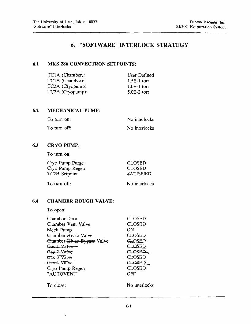
6. II SOFTWARE II INTERLOCK STRATEGY
6.1 MKS 286 CONVECTRON SETPOINTS:
TClA (Chamber):TClB (Chamber):TC2A (Cryopump):TC2B (Cryopump):
6.2 MECHANICAL PUMP:
To tum on:
To tum off:
6.3 CRYO PUMP:
To tum on:
Cryo Pump PurgeCryo Pump RegenTC2B Setpoint
To tum off:
6.4 CHAMBER ROUGH VALVE:
To open:
Chamber DoorChamber Vent ValveMech PumpChamber Hivac Valve
·ehamber WiJla€ aYf)aSS valYeGa£ 1 ValveGas 2 Valve~(Jas 3 ValVeGas 4 valveCryo Pump Regen"AUTOVENT"
To close:
User Defined1.5E-l torr1.OE-l torr5.0E-2 torr
No interlocks
No interlocks
CLOSEDCLOSEDSATISFIED
No interlocks
CLOSEDCLOSEDONCLOSEDg QSEPGLOSlillGL08BD '"CLOSEDCLOSEDCLOSEDOFF
No interlocks
~1
The University of Utah, Job #: 18097"Software" Interlocks
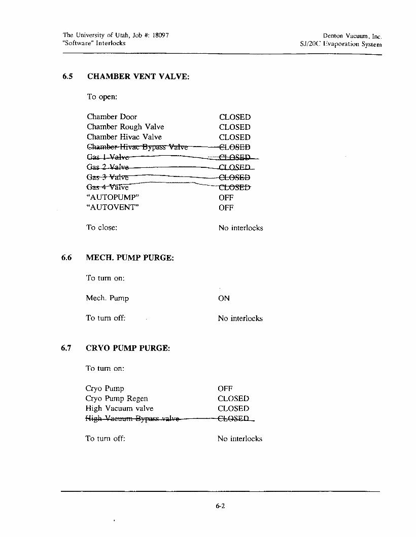
6.5 CHAMBER VENT VALVE:
To open:
Chamber Door CLOSEDChamber Rough Valve CLOSEDChamber Hivac Valve CLOSEDGhameef IIivac Bypass Valve CLOSEDGiaa£-li:..ll~'V,/a~l~vee------------.:::=:::te::JJI:;j.ot!S:SE:~Dl.-Gas 2 Valve ClOSED
Gas 3 Valve CLOSESBas 4 "Valve- ---- CLOSED"AUTOPUMP" OFF"AUTOVENT" OFF
Denton Vacuum, Inc.SJ/20C Evaporation System
To close:
6.6 MECH. PUMP PURGE:
To tum on:
Mech. Pump
To tum off:
6.7 CRYO PUMP PURGE:
To tum on:
Cryo PumpCryo Pump RegenHigh Vacuum valveHigh Vaetltlfft Bypass valv@
To tum off:
No interlocks
ON
No interlocks
OFFCLOSEDCLOSEDCLOSED
No interlocks
6-2
The University of Utah, Job #: 18097"Software" Interlocks
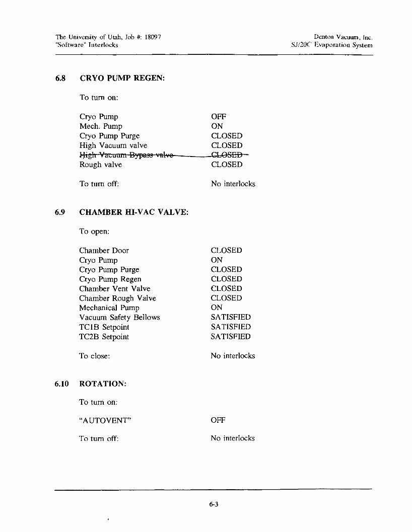
6.8 CRYO PUMP REGEN:
To tum on:
Cryo PumpMech. PumpCryo Pump PurgeHigh Vacuum valve~igh Vacuum Bypass 'f'illveRough valve
To tum off:
6.9 CHAMBER HI-VAC VALVE:
To open:
Chamber DoorCryo PumpCryo Pump PurgeCryo Pump RegenChamber Vent ValveChamber Rough ValveMechanical PumpVacuum Safety BellowsTC1B SetpointTC2B Setpoint
To close:
6.10 ROTATION:
To tum on:
"AUTOVENT"
To tum off:
OFFONCLOSEDCLOSEDCLOSEDCLOSED
No interlocks
CLOSEDONCLOSEDCLOSEDCLOSEDCLOSEDONSATISFIEDSATISFIEDSATISFIED
No interlocks
OFF
No interlocks
6-3
Denton Yacuum. Inc.SJ/20C Evaporation System

The University of Utah, Job #: 18097"Software" Interlocks
6.11 HEAT POWER:
To tum on:
Cryo PumpRotationTC18 SetpointVacuum safety(*)Chamber door(*)Gun Water Flowswitch(*)Heat Water Flowswitch(*)"AUTOVENT"
To tum off:
6.12 SHUTTER:
To open:
"AUTOVENT"
To close:
ONONSATISFIEDSATISFIEDCLOSEDSATISFIEDSATISFIEDOFF
No interlocks
OFF
No interlocks
Denton Vacuwn, Inc.SJ/20C Evaporation System
6.13 SHIFf FUNCTION:
To tum on:
"AUTOPUMP" OFF"AUTOVENT" OFF"AUTOREGEN" OFF
To tum off: No interlocks
6.14 AUTOREGEN:
To tum on:
"AUTOPUMP" OFF"AUTOVENT" OFF"MAINTENANCE" OFF
To tum off: No interlocks
6-4
The University of Utah, Job #: 18097"Software" Interlocks
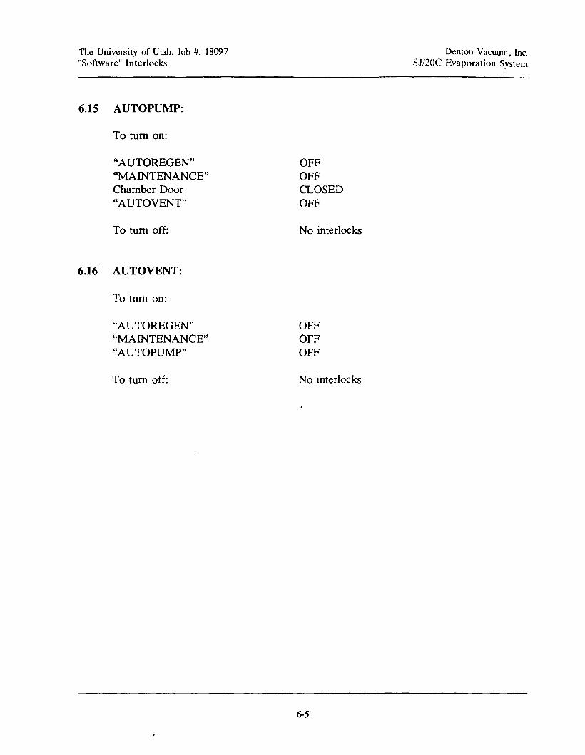
6.15 AUTOPUMP:
To turn on:
"AUTOREGEN""MAINTENANCE"Chamber Door"AUTOVENT"
To turn off:
6.16 AUTOVENT:
To turn on:
"AUTOREGEN""MAINTENANCE""AUTOPUMP"
To turn off:
OFFOFFCLOSEDOFF
No interlocks
OFFOFFOFF
No interlocks
6-5
Denton Vacuwn, Inc.SJ/20C Evaporation System
The University of Utah, Job #: 18097"Software" Interlocks
6-6
Denton Vacuum, Inc.SJ/20C Evaporation System

The University of Utah, Job # 18097Troubleshoot ing
7. TROUBLESHOOTING
7.1 INTRODUCTION
WARNING!
Denton Vacuwn, Inc.SJ/2OC Evaporation System
DUE TO THE NATURE OF HOW A VACUUMSYSTEM OPERATES, THERE ARE MANY TYPES OFVOLTAGES ON A VACUUM CHAMBER.
BEFORE ATTEMPTING ANY TYPE OF TROUBLESHOOTING ON THE VACUUM SYSTEM OR ANYSUBSYSTEM, REFER TO PROPER SECTION OF THEOPERATING MANUAL FIRST TO CHECK IF THESYSTEM IS BEING OPERATED IN THE PROPERMANNER. THERE MIGHT BE AN INTERLOCKPARAMETER BEING OVERLOOKED, RATHER THANA SYSTEM FAILURE.
7.2 BASIC TOOL REQUIREMENTS
NOTE ON JEWELRY
When working around a vacuum system,there is one good practice,
DO NOT WEAR ANY JEWELRY!
AN ARC MAYBE DRAWN FROM A HIGH VOLTAGE SOURCE!
7-1
The University of Utah, Job # 18097Troubleshooting
Denton Vacuum, Inc.SJ/2OC Evaporation System
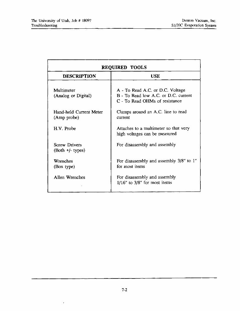
REQUIRED TOOLS
DESCRIPTION USE
Multimeter A - To Read A.C. or D.C. Voltage(Analog or Digital) 8 - To Read low A.C. or D.C. current
C - To Read OHMs of resistance
Hand-held Current Meter Clamps around an A.C. line to read(Amp probe) current
H.V. Probe Attaches to a multimeter so that veryhigh voltages can be measured
Screw Drivers For disassembly and assembly(Both +/- types)
Wrenches For disassembly and assembly 3/8" to I"(Box type) for most items
Allen Wrenches For disassembly and assembly1/16" to 3/8" for most items
7-2
The University of Utah, Job # 18097Troubleshoot ing
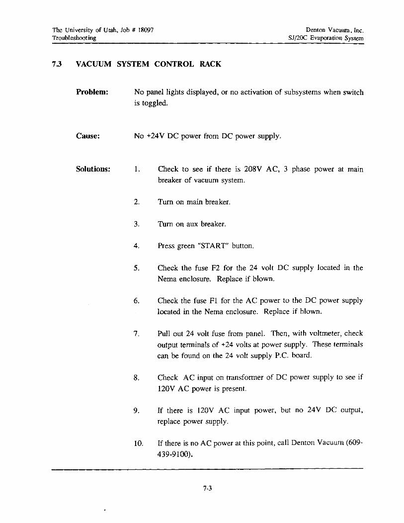
7.3 VACUUM SYSTEM CONTROL RACK
Denton Vacuwn, Inc.SJ/2OC Evaporation System
Problem:
Cause:
No panel lights displayed, or no activation of subsystems when switch
is toggled.
No +24V DC power from DC power supply.
Solutions: 1. Check to see if there is 208V AC, 3 phase power at main
breaker of vacuum system.
2. Turn on main breaker.
3. Turn on aux breaker.
4. Press green "START" button.
5. Check the fuse F2 for the 24 volt DC supply located in the
Nema enclosure. Replace if blown.
6. Check the fuse FI for the AC power to the DC power supply
located in the Nema enclosure. Replace if blown.
7. Pull out 24 volt fuse from panel. Then, with voltmeter, check
output terminals of +24 volts at power supply. These terminals
can be found on the 24 volt supply P.e. board.
8. Check AC input on transformer of DC power supply to see if
120V AC power is present.
9. If there is 120V AC input power, but no 24V DC output,
replace power supply.
10. If there is no AC power at this point, call Denton Vacuum (609
439-9100).
7-3
The University of Utah, Job # 18097Troubleshooting
Denton Vacuwn, Inc.SJ/2OC Evaporation System
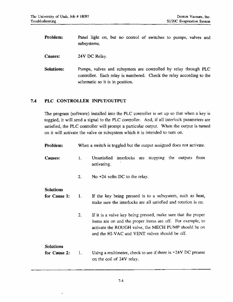
Problem:
Causes:
Solutions:
Panel light on, but no control of switches to pumps, valves and
subsystems.
24V DC Relay.
Pumps, valves and subsystem are controlled by relay through PLC
controller. Each relay is numbered. Check the relay according to the
schematic so it is in position.
7.4 PLC CONTROLLER INPUT/OUTPUT
The program (software) installed into the PLC controller is set up so that when a key is
toggled, it will send a signal to the PLC controller. And, if all interlock parameters are
satisfied, the PLC controller will prompt a particular output. When the output is turned
on it will activate the valve or subsystem which it is intended to turn on.
Problem: When a switch is toggled but the output assigned does not activate.
Causes: 1. Unsatisfied interlocks are stopping the outputs from
activating.
2. No +24 volts DC to the relay.
Solutionsfor Cause 1: 1. If the key being pressed is to a subsystem, such as heat,
make sure the interlocks are all satisfied and rotation is on.
2. If it is a valve key being pressed, make sure that the proper
items are on and the proper items are off. For example, to
activate the ROUGH valve, the MECH PUMP should be on
and the HI-VAC and VENT valves should be off.
Solutionsfor Cause 2: 1. Using a multimeter, check to see if there is +24V DC present
on the coil of 24V relay.
7-4

The University of Utah, Job # 18097Troubleshoot ing
NOTE
Denton Vacuwn, Inc.SJ/2OC Evaporation System
KEEP IN MIND THAT THIS PART OFTHE TROUBLESHOOTING MANUAL ASSUMESTHAT THE POWER SUPPLIES ARE GOOD,BECAUSE THE FRONT PANEL LEDs ARE LITAND THE INPUTS ARE RECEIVING A SIGNALTO ACTIVATE THEM.
IF THIS IS NOT TRUE, THEN REFER TOTHE FIRST PART OF THE TROUBLESHOOTING MANUAL FIRST TO DETERMINE IFTHE POWER SUPPLIES ARE GOOD.
2. Check relay.
7.5 VALVES AND SHUTfERS
All the pumping valves and the source shutter on the vacuum system are pneumaticallycontrolled.
The valve operation procedure is as follows:
There is a 24V DC signal from an output relay that feeds into a DC solenoid(electromagnetic) coil. The electromagnetic field created by the coil pulls up a "plunger
valve" mounted to the air flow manifold. When this "plunger" is pulled up it permits airpressure (80 to 100 psi) to pass through the manifold into an air operated cylinder. The
air pressure going into the air cylinder becomes greater on one side of the cylinder than
on the other side. The side of the cylinder with the greater air pressure will move a
"diaphragm" the opposite way. Depending on which way the "diaphragm" is travelling
the valve is being opened or closed.
Problem: When the assigned output is activated the valve or shutter associated with
it does not respond. But the panel indicator light turns green.
7-5
The University of Utah, Job # 18097Troubleshooting
Denton Vacuum, Inc.SJj20C Evaporation System
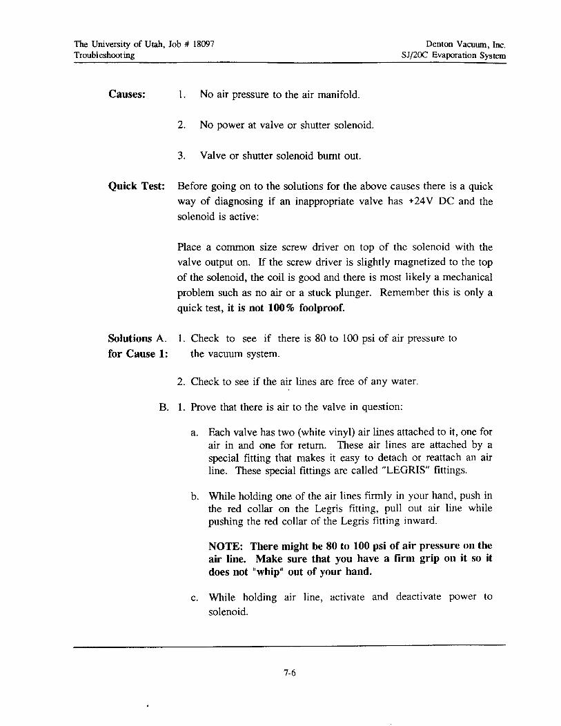
Causes: 1. No air pressure to the air manifold.
2. No power at valve or shutter solenoid.
3. Valve or shutter solenoid burnt out.
Quick Test: Before going on to the solutions for the above causes there is a quick
way of diagnosing if an inappropriate valve has +24V DC and the
solenoid is active:
Place a common size screw driver on top of the solenoid with the
valve output on. If the screw driver is slightly magnetized to the top
of the solenoid, the coil is good and there is most likely a mechanical
problem such as no air or a stuck plunger. Remember this is only a
quick test, it is not 100% foolproof.
Solutions A.for Cause 1:
1. Check to see if there is 80 to 100 psi of air pressure to
the vacuum system.
2. Check to see if the air lines are free of any water.
B. 1. Prove that there is air to the valve in question:
a. Each valve has two (white vinyl) air lines attached to it, one forair in and one for return. These air lines are attached by aspecial fitting that makes it easy to detach or reattach an airline. These special fittings are called "LEGRIS" fittings.
b. While holding one of the air lines firmly in your hand, push inthe red collar on the Legris fitting, pull out air line whilepushing the red collar of the Legris fitting inward.
NOTE: There might be 80 to 100 psi of air pressure on theair line. Make sure that you have a firm grip on it so itdoes not IIwhip II out of your hand.
c. While holding air line, activate and deactivate power to
solenoid.
7-6

The University of Utah, Job # 18097Troubleshooting
Denton Vacuum, Inc.SJ/2OC Evaporation System
Solutionsfor Cause 2:
d. Air should flow out of the Legris fitting mounted in the airmanifold when power is at one state, and air should stopflowing when the power to the solenoid is in the other state. "State" being ON or OFF.
e. Repeat steps 3, 4 and 5 for the second air line to see if itoperates the same way.
f. If both Legris fittings operate with alternating air on and off,the problem is in the valve assembly itself.
2. Disassemble valve in question to see if there is any foreign matterlodged in it or if a seal is broken.
3. If the air flow coming out of the Legris fittings did not change fromone port to the other, when the valve switch was activated ordeactivated, then disassemble the Humphry solenoid attached to thetop of the air manifold to see if that assembly is intact.
1. Locate the Humphry -valve, attached to the air manifold,that is in question.
2. Open the black plastic enclosure that holds the wires connecting tothe solenoid.
3. When the wires have been located, expose the connectors that jointhe power wires to the solenoid.
4. Place a volt meter across the wires at the crimp connectors.
5. Also disconnect the solenoid from the output leads and try to read+24V DC power at the ends of the two wires.
6. If there is NO power at the solenoid when the output is high, usingthe subsystem schematic and volt meter, trace the lines to see ifthere is a break in the signal path.
7-7
The University of Utah, Job # 18097Traubleshoot ing
Denton Vacuwn, Inc.SJ/2OC Evaporation System
7. If there is power now that the solenoid is not attached, then thesolenoid is shorted out.
8. Using an ohm meter, read the resistance of the solenoid. If theresistance is 00.0, then the solenoid is shorted out.
9. Replace solenoid, then try valve.
Solutions 1. Disconnect solenoid from power leads.for Cause 3:
2. Using an ohm meter, read the resistance of the coil.
3. If the coil is good, it should have a resistance of about 65 to 85ohms ±10 percent.
4. If the coil reads infinity, then it is burnt out.
5. Replace the coil and try valve.
7.6 ROTATION
Problem:
Causes:
Solutionsfor Cause 1:
When rotation is powered on it does not rotate, or it stops rotating in themiddle of a run.
1. Fuse blown.
2. Power to and/or from the motor controller is not active.
3. Mechanical jam-up.
1. Located in the power distribution enclosure, on the frameof the vacuum system, is an SCR Controller.
2. Shut power before step 3 is executed.
3. There is a fuse holder with a 1 amp fuse (FU-6).
7-8
The University of Utah, Job # 18097Troubleshoot ing
4. Remove the fuse, check it. If blown, replace.
Denton Vacuum, Inc.SJ/2OC Evaporation System
Solutions A 1. Using a volt meter, measure the l20V AC powerfor Cause 2: going into the controller.
2. If no power is present, trace the circuit using the rotation schematicand a volt meter.
Solutions Afor Cause 3:
1. Check to see if the chain is too loose or too tight.If too loose, the motor will tum but the chain will not hold onto thegear so as to tum the planetary.
2. If the timing belt is too tight, the motor will not have enough torqueto overcome the tension of the chain.
7.7 SUBSTRATE HEAT
7.7.1 SCR Controller
The silicon control rectifier (SCR) controller is a solid state device designed to controla large AC power level with a small DC control signal.
The input of the SCR has a 208 VAC input protected by circuit breakers to limit thecurrent that will be seen by the SCR controller. As the DC signal to the gate of the SCRincreases so does the output of the SCR controller. The SCR controller is about 95%efficient. This means for a given input the output voltage will achieve 95% of the actualinput voltage. An SCR has a preset gain and span set on it. If these parameters arereadjusted, it will limit the control range of the SCR either at the low end or the highend.
Beside being able to control the SCR with an external 0 to 10 Volt DC source, it can be
controlled by an internal signal from its own source of power. This is done by removingthe 0 to 10 DC signal from the "W" and "CCW" terminals, then attaching a (l K ohm)pot to the "CW, W, CCW" terminals of the SCR. An SCR controller has one unusualproperty. If there is no "LOAD" attached to the output, the SCR will pass full voltageno matter where the DC control voltage is set.
7-9
The University of Utah, Job # 18097Troubleshoot ing
Denton Vacuwn, Inc.SJ/2OC Evaporation System
Problem:
Causes:
No output from SCR.
1. No control signal.
2. SCR device defective.
3. 24 VAC control transformer does not output 24 VAC.
Solutionfor Cause 1: 1. Measure control signal and check if it is 0 to 10 VDC.
Solutionsfor Cause 2: 1. With all wiring attached to the SCR, read the 0-10 VDC control signal
to the SCR.
2. Prove that input control voltage is present.
3. Prove that the AC power voltage is present.
4. With heater coils connected to the output, place a voltmeter across theoutput terminals of the SCR.
NOTE
Insure that chamber is under vacuum toprevent coil embrittlement.
5. a. If there is a constant high voltage present, of 190 VAC, with verylittle or no change when the setpoint is changed, then the SCR isshorted out.
b. Replace SCR module mounted to the heat sink.
6. a. If there is no voltage present at all, the SCR is burnt out and"open."
7-10

The University of Utah, Job # 18097Troubleshooting
b. Replace SCR module.
Solutions for 1. Check input voltage to 24 VAC transformer.Cause No.3 It. shoud be 208 VAC.
Denton Vacuum, Inc.SJ/2OC Evaporation System
2. If input voltage is present, check output voltage. It should be 24 VAC.
3. If output voltage is not present, substitute transformer.
7.8 SUMMARY
Troubleshooting procedures are the same whether it is a vacuum system, your homeaudio/visual system or an automobile.
Steps for troubleshooting are to be done in a logical order.
This manual reviews the most vulnerable parts of a vacuum system's operation. If avacuum system is maintained properly, it will give many years of uninterrupted service.
When a vacuum system is constructed, there are many different vendor parts used in thevacuum system, everything from the pumps to the gas flow controllers. Each sub systemis supplied with a manual of operation. Refer to these manuals for troubleshootingprocedures on the individual equipment in question.
If after a reasonable time the problem cannot be found, call Denton Vacuum (609-43991(0) to help with the problem and help reduce down time.
7-11
The University of Utah, Job # 18097Troubleshoot ing
7-12
Denton Vacuwn, Inc.SJj20C Evaporation System

The University of Utah, Job # 18097Preventive Maintenance
Denton Vacuum, Inc.SJ/20C Evaporation System
11. PREVENTIVE MAINTENANCE
11.1 MECHANICAL PUMP
1. Check oil level daily.DO THIS WHEN PUMP IS OPERATING. However, do not add oilwhile the pump is operational.
2. Check the color of the oil monthly. Compare it with a sample of new oil. IFTHE OIL IS BROWN OR BLACK, IT HAS DETERIORATED.DRAIN THE PUMP AND CHANGE THE OIL. See Troubleshootingsection of the operating manual.
11.2 DEPOSITION CHAMBER
Ensure that no build-up of deposition material(s) occurs on the chamber walls andbaseplate. Line chamber with disposable foil (degreased, heavy-gauge aluminum foilworks well) and replace on a periodic (dependent on system use) basis.
11.3 CRYOPUMP COMPRESSOR
1. Check the pressure gauge on the compressor daily.Pressure needs to be 195 to 205 psig at ambient temperature. Check manual.
2. Check the cooling water temperature. The inlet should be a minimum of 4()o F.(l()()o F. maximum) 2.5 gpm flow.
3. Replace compressor absorber every 4,500 hours. See Troubleshooting section ofthe operating manual.
11.4 CRYOPUMP
1. Check the temperature gauge daily.
The reading should be 20K or less. Any temperature reading more than 20K is anindication of abnormal operation or that the pump requires regeneration. SeeTroubleshooting section of the operating manual.
II-I
The University of Utah, Job # 18097Preventive Maintenance
11.5 PUMPING SYSTEM
Denton Vacuum, Inc.SJ/20C Evaporation System
1. Check the poppet valve assembly monthly.a) Bellows should be straight, not twisted.b) Movement of the poppet plate must be smooth and finn. If jagged, replace
supporting bushing.
2. Check the soft connection between the mechanical pump and piping daily fordamage.
3. Check all piping connections for looseness or damage weekly.
4. Check all air lines connected to the pneumatic valves for leaks or damage weekly.
11-2

The University of Utah, Job # 18097Spare Parts List
SECTION 8
SPARE PARTS LIST
8-1
Denton Vacuwn, Inc.SJj20C Evaporation System

8033-370University of Utah
DENTONSJ/20
SPARE PARTS LIST PAGE 1 OF 1
VACUUMINC.
VACUUM CHAMBER JOB # 18097
PART NO. OESCRIPTION LOCATION QTY. PRICEEA.
5015-453 a-RING TOP FLANGE 1 $42.00
5015-347 a-RING DOOR VIEWPORTS 2 14.95
5015-010 a-RING DOOR SHUTTER ROTARY MOTION 4 1.00
5015-210 ! a-RING DOOR SHUTTER ROTARY MOTION 2 1.00
5015-517 O-RING DOOR 1 100.85
.. \
5015-218 a-RING 1.00 BLANK PORTS 10 1.00
G-275 COPPER GASKET CHAMBER 2.75 CONFLAT PORTS 4 3.50
5106-004 SIGHT GLASS DOOR VIEWPORT 1 82.55
5094-008 COMPRESSION SPRING DOOR SHUTTER ROTARY MOTION 2 4.10
ALL PRICES SUBJECT TO CHANGE MINIMUM ORDER $25 FOB MOORESTOWN, NEW JERSEY 02l97SW

8033-370Universi ty of Utah
DENTONSJ/20
SPARE PARTS LIST PAGE 1 OF 1
VACUUMINC.
PUMPING SYSTEM JOB # 18097
PART NO. DESCR IPTION LOCATION QTY. PRICEEA.
5015-466 L O-RING CHAMBER TO BASEPLATE 1 $62.50
5013-240 O-RING VALVE BODY PORT 1 4.20
5013-257 O-RING POPPET PLATE 1 1.60
5013-227 O-RING POPPET VALVE 1 1.00
5015-326 O-RING FLANGES - NW40 2 2.50
ION GAUGE TUBE COMPRESSION5015-116 O-RING SEAL 2 1.00
5015-314 O-RING FLANGES - NW16 4 2.00
5015-320 O-RING FLANGES - NW25 6 2.25
5013-012 O-RING 1.12" VALVES 2 1.00
5013-215 O-RING 1.12" VALVES 2 1.00
5013-226 O-RING 1.12" VALVES 2 1.00
5015-172 O-RING 8.00" CRYOPUMP 1 27.50
AlL PRICES SUBJECT TO C.,ANGE MINIMUM ORDER $25 FOB MOORESTOWN, NEW JERSEY 02/97SW

8033-370
Unlversl tv of Utah
DENTON SJ/20PAGE 1 OF 1
VACUUM SPARE PARTS LISTINC.
E-BEAM SOURCE & SHUTTER JOB # 18097
PART NO. OESCR IPTION LOCATION QTY. PRICEEA.
5015-218I
O-RING 3fs" ROTARY FEEDTHROUGH 1 1.00
5015-012 ! O-RING 3fs" ROTARY FEEDTHROUGH 3 1.00
5015-013 O-RING 3fs" ROTARY FEEDTHROUGH 1 1.00
5015-216 O-RING HIGH-VOLTAGE FEEDTHROUGH 2 1.00
5015-220 O-RING DUAL WATER FEEDTHROUGH 1 1.15
5015-021 O-RING OCTAL HEADER FEEDTHROUGH 1 1.00
B10-1 BEARING 3fs" ROTARY FEEDTHROUGH 2 36.50
A7-120 BEARING SHAFT 3f&" ROTARY FEEDTHROUGH 1 26.20
LC-063H-6-SS COMPRESSION SPRING 3fs" ROTARY FEEDTHROUGH 1 5.25
5000-75 RETAINING RING 3fs" ROTARY FEEDTHROUGH 2 1.00
ALL PRICES SUBJECT TO CHANGE MINIMUM ORDER $25 FOB MOORESTOWN, NEW JERSEY 02/97SW
8033-370Unlversl ty of Utah
DENTONSJ/20
SPARE PARTS LIST PAGE 1 OF 1
VACUUMINC.
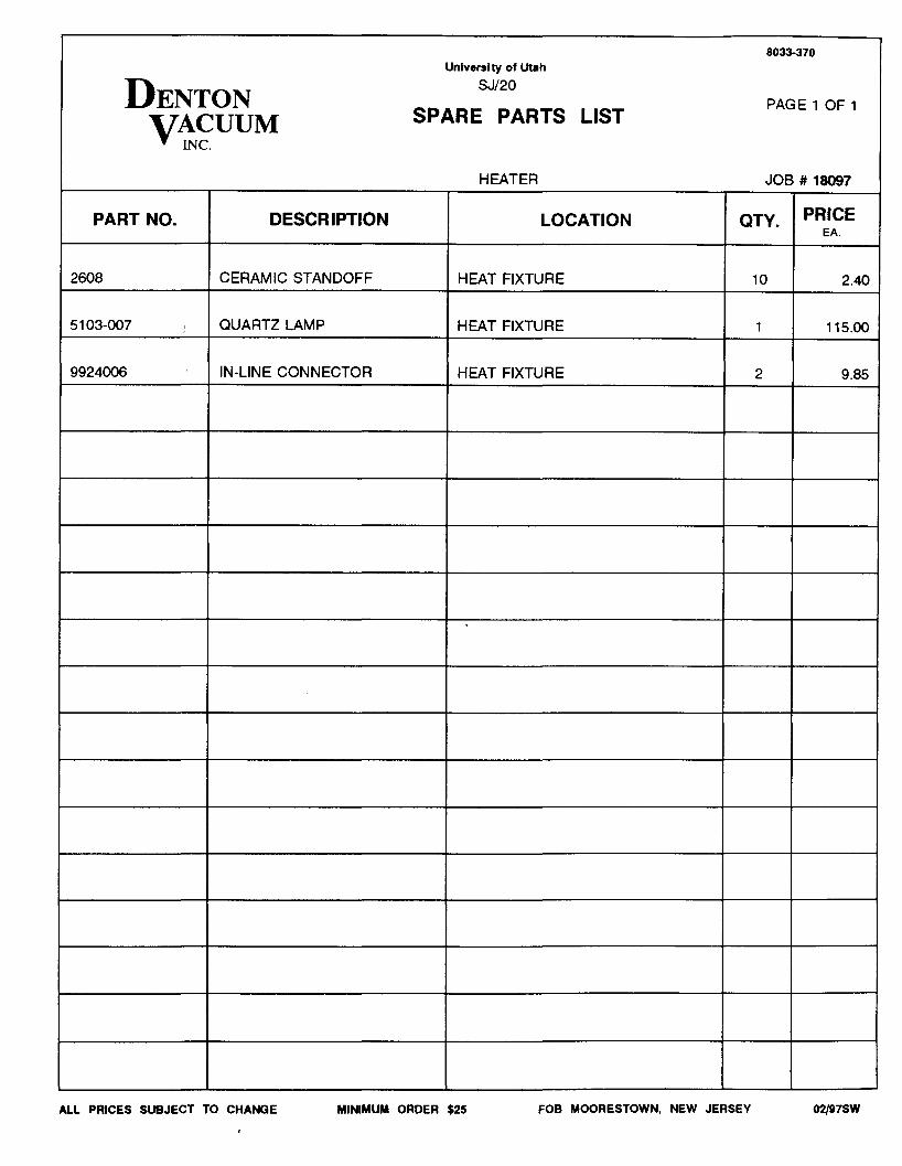
HEATER JOB # 18097
PART NO. DESCRIPTION LOCATION QTY. PRICEEA.
2608 CERAMIC STANDOFF HEAT FIXTURE 10 2.40
5103-007 I QUARTZ LAMP HEAT FIXTURE 1 115.00
9924006 IN-LINE CONNECTOR HEAT FIXTURE 2 9.85
ALL PRICES SUBJECT TO CHANGE MINIMUM ORDER $25 FOB MOORESTOWN, NEW JERSEY 02/97SW

8033-370UnIversI ty of Utah
DENTON SJ/20PAGE 1 OF 1
VACUUM SPARE PARTS LISTINC.
ROTATION ASSEMBLY JOB # 18097
PART NO. DESCRIPTION LOCATION QTY. PRICEEA.
5015-252 O-RING 1.00 ROTARY FEEDTHROUGH 1 6.95
oo5-137000A U-CUP SEAL 1.00 ROTARY FEEDTHROUGH 2 16.85
Jhili :.' . -\',1641DC BEARING - RADIAL 1.00 ROTARY FEEDTHROUGH 2 28.50
5000-200 RETAINING RING 1.00 ROTARY FEEDTHROUGH 1 1.00
5000-250 RETAINING RING 1.00 ROTARY FEEDTHROUGH 1 1.90
5100-100 RETAINING RING 1.00 ROTARY FEEDTHROUGH 1 1.00
ALL PRICES SUBJECT TO CHANGE MINIMUM ORDER $25 FOB MOORESTOWN, NEW JERSEY 02j97SW
8033-370University of Utah
DENTON SJ/20
SPARE PARTS LIST PAGE 1 OF 1
VACUUMINC.
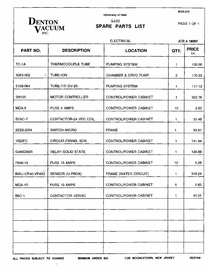
ELECTRICAL JOB # 18097
PART NO. DESCRIPTION LOCATION CTY. PRICEEA.
TC-1A THERMOCOUPLE TUBE PUMPING SYSTEM 1 130.00
5083-002 V" TUBE-ION CHAMBER & CRYO PUMP 2 170.33
5108-004 TUBE-TIC DV-23 PUMPING SYSTEM 1 117.13
SH125 MOTOR CONTROLLER CONTROUPOWER CABINET 1 322.76
MDA-5 FUSE 5 AMPS CONTROUPOWER CABINET 10 2.60
BC6C-Y ! CONTACTOR-24 VDC COIL CONTROUPOWER CABINET 1 55.48
BZE6-2RN SWITCH-MICRO FRAME 1 93.81
1022FC CIRCUIT-FIRING, SCR CONTROUPOWER CABINET 1 141.44
G480D90R RELAY-SOLID STATE CONTROUPOWER CABINET 1 126.88
FNW-15 FUSE 15 AMPS CONTROUPOWER CABINET 10 5.28
Bil5U-C P40-VP4X~/ SENSOR (U-PROX) FRAME (WATER CIRCUIT) 1 318.24
MDA-10 FUSE 10 AMPS CONTROUPOWER CABINET 5 5.85
B6C-1 CONTACTOR 120VAC CONTROUPOWER CABINET 1 45.55
AlL PRICES SUBJECT TO CHANGE MINIMUM ORDER $25 FOB MOORESTOWN, NEW JERSEY 02/97SW
The University of Utah, Job # 18097 Denton Vacuum, Inc.Electrical Schematics SJ/20C Evaporation System
9. ELECTRICAL SCHEMATICS
LOCATED IN BINDER
9-1
The University of Utah, Job # 18097Mechanical Drawings
10. MECHANICAL DRAWINGS
LOCATED IN BINDER
10-1
Denton Vacuum, Inc.SJ/20C Evaporation System